Article

Dehydrogenation of Metal Hydride Reactor-Phase Change Materials Coupled with Light-Duty Fuel Cell Vehicles

1
HySA Systems Competence Centre, South African Institute for Advanced Materials Chemistry, University of the Western Cape, Private Bag X17, Bellville 7535, South Africa
2
Faculty of Electrical Engineering, Mechanical Engineering and Naval Architecture, University of Split, R Boskovica 32, 21000 Split, Croatia
3
Faculty of Mechanical Engineering, Lublin University of Technology, Nadbystrzycka 36, PL-20-618 Lublin, Poland
*
Author to whom correspondence should be addressed.
Energies 2022, 15(9), 2982; https://doi.org/10.3390/en15092982
Submission received: 25 February 2022 / Revised: 1 April 2022 / Accepted: 15 April 2022 / Published: 19 April 2022
(This article belongs to the Special Issue Advanced Studies for PEM Fuel Cells in Hydrogen-Fueled Vehicles)

Abstract

:
The popularity of using phase change materials (PCMs) for heat storage and recovery of metal hydrides’ reaction has grown tremendously. However, a fundamental study of the coupling of such a system with a low-temperature PEM (polymer electrolyte membrane) fuel cell is still lacking. This work presents a numerical investigation of the dehydrogenation performance of a metal hydride reactor (MHR)-PCM system coupled with a fuel cell. It is shown that to supply the fuel cell with a constant H2 flow rate, the PCM properties need to be in an optimized range. The effects of some design parameters (PCM freezing point, the initial desorption temperature, the nature and the size of the PCM) on the dehydrogenation performance of MHR-PCM system are discussed in detail. The results showed that the MHR-PCM could supply hydrogen at 12 NL/min only for 20 min maximum due to the significant endothermic effect occurring in the MHR. However, reducing the requested H2 flowrate to 5.5 NL/min, the hydrogen desorption to a fuel cell is prolonged to 79 min. Moreover, this system can accommodate different PCMs such as paraffin and salt hydrates for comparable performance. This study demonstrates the ability of MHR-PCM systems to be used as range extenders in light-duty fuel cell vehicles.

1. Introduction

During the years, metal hydrides have been considered as potential candidates for hydrogen storage applications due to their attributes, such as high hydrogen storage capacity and their offer of reasonable safety limits [1]. However, a significant challenge remains, which is the thermal management during the hydrogen storage/restore [2,3]. As it is well known, the reaction of metal with hydrogen is highly exothermic. Therefore, to store hydrogen in metal for a short time, a tremendous amount of heat should be transferred out. Moreover, functional metal hydrides are usually in the form of a powder. In this form, metal hydrides possess low thermal conductivity, generally close to or less than 1 W/mK. As a result, many techniques of heat transfer improvement have been suggested. These techniques include the insertion of metal foams [4,5], copper matrices [6], heating/cooling tube [7], finned-tube heat exchangers [8,9], etc.
Adopting active thermal management such as multiple heating/cooling tubes [7] finned-tube affects the hydrogen storage overall efficiency [10], as pumping power is required at any stage of the hydrogen sorption cycle. Moreover, concerning the energy storage efficiency, the heat necessary to drive the endothermic reaction is higher than the heat produced during the exothermic reaction. As a result, finding a system that can store the heat evolved during hydrogen absorption and reuse it during hydrogen desorption is the subject of recent research. Phase change materials (PCM) can fulfill this task by liquifying and freezing as they absorb or release heat, respectively. Recently, many researchers [11,12,13,14,15,16,17,18] have discussed the application of PCM in the thermal management of metal hydrides-based hydrogen storage applications. Garrier et al. [11] conducted an experimental study on the performance of a MgH2 tank coupled with a eutectic mixture Mg-Zn PCM. The hydrogen desorption of a pilot tank containing 7000 NL of hydrogen was discussed. The H2 desorption was completed in 3 h, with an efficiency of 70%. They pointed out that the decrease in efficiency was due to losses from the PCM jacket. Following that work, several numerical studies have been reported to optimize the metal hydride reactors (MHR)-PCM system. Mellouli et al. [12] investigated numerically the performance of Mg-based hydride equipped with Mg-Zn PCM using different configuration tank designs. The results showed that the spherical tank design gives a better performance than the cylindrical one. Darzi et al. [13] reported a numerical model of a long tubular metal hydride reactor integrating a PCM cooling/heat jacket for H2 absorption/desorption. The results showed that PCM melting/freezing rates depend closely on the hydrogen absorption/desorption pressures. Moreover, the bed porosity greatly affected the PCM freezing during the H2 desorption process. Also, metal-foam insertion into the PCM has significantly reduced H2 absorption/desorption times. Tong et al. [14] systematically studied the performance of metal hydride equipped with PCM jacket. They developed and validated a 2-D numerical model for H2 absorption processes. The effect of the PCM’s properties on the H2 absorption/desorption time was studied. The results showed that the latent heat of the PCM has a more pronounced effect on the MHT performance compared to its thermal conductivity. Ben Maad et al. [15] investigated numerically the dehydrogenation performance of a high-temperature hydride material incorporating a PCM jacket. Their model included radiative heat loss, which was neglected in the study by Mellouli. The PCM adopted in this study was a metallic eutectic mixture of Mg-Zn-Al, as the melting point could reach 600 °C. The investigation results showed that the reactor desorbed all H2 in less than 2.5 h. Nyamsi et al. [16] numerically investigated the effect of integrating a PCM jacket into two-tank heat storage systems for industrial waste-heat recovery. The impact of the PCM properties and PCM jacket size on the energy density and power output were systematically analyzed. The results showed that the melting point and the thermal conductivity of the PCM had a significant impact on the performance indicators. Ye et al. [17] proposed an MHR-PCM system where the PCM disk is sandwiched between two metal hydride layers. The numerical simulations showed that this proposed structure has better heat transfer characteristics than the MH tank’s conventional structure surrounding the PCM jacket. Tong et al. [18] discussed the hydrogen desorption of an MHR-PCM system. The design consisted of MH tank encircled by a PCM jacket plus a coiled water circulation channel. The effects of some operating parameters such as outlet pressure and the water temperature on the H2 release performance have been studied. Finally, they reported some fitted models of hydrogen desorption rate as a function of water temperature, outlet pressure, and overall heat-transfer coefficient. Facci et al. [19] conducted the modeling and optimization design of a PCM-enhanced hydrogen storage device. A numerical solver based on hybrid lattice Boltzmann Phase Field (LB-PF) algorithm was proposed and developed. This present model allowed for the calculation of the heat flux density released by the metal hydride during the H2 charging process in the PCM. The results of the Nusselt numbers are utilized to design enhanced metal hydride-based energy storage systems for the reliable and cost-effective hydrogen economy. Nguyen and Shabani [20] proposed an MHR-PCM in a context of a standalone solar H2 system. The optimal system architecture and yearly power profiles of H2 production and utilization was simulated using the HOMER software. The dynamic simulation of MHR-PCM was conducted in the MATLAB environment. The results showed that around 12% of energy content of H2 produced by the electrolyzer could be saved only if the active thermal management of hydride-based hydrogen storage was replaced by phase change materials. Furthermore, it was found that for practical hydrogen utilization by fuel cells, the PCM thermal conductivity should be enhanced to a minimum of 1.5 W/mK. Alqahtani et al. [21] proposed a novel design of MHR-PCM consisting of cascade layers of PCMs. The design arranges in a series different PCM with various melting temperatures and latent heat. A parametric study helped at finding the optimum arrangement of PCM layers. Moreover, the results indicated that the cascaded MHR-PCM design improved the heat transfer rate by shortening the hydrogen absorption and desorption times by 26 and 51%, respectively, compared to the conventional design consisting of a single layer of PCM.
PCMs have a very low intrinsic thermal conductivity, which in some cases are lower than that of metal hydrides. As a result, some efforts are spent on strengthening the heat transfer by inserting metal foams, carbon-based materials, or fins. Ling et al. [22] demonstrated that the insertion of 25 and 30 wt.% of graphite dramatically improves the thermal conductivity, but at the same time decreases the latent heat from 226 kJ/kg for pure paraffin to 168.1 and 152.5 kJ/kg. Warzoha et al. [23] showed that the insertion of graphite by only 2.8 to 11.4 vol.% increases the thermal conductivity by up to 170–190%. Zheng et al. [24] reported that the insertion of copper foam into paraffin enhances the thermal conductivity by 120.5%. In contrast, fins can improve the thermal conductivity of PCM without modifying its intrinsic properties, just by providing a heat transfer path from the PCM to the heat source/sink. Erek et al. [25] investigated numerically and experimentally the transient behavior of a PCM solidification filled into a shell-and-tube unit equipped with annular fins. The effects of fin parameters on the solidification process were studied. The results showed that the solidification time was reduced by a maximum of 20% when the fin height was increased or fin spacing was decreased. Rathod and Barnerjee [26] conducted an experimental study of latent heat using PCMs. They used longitudinal fins to improve the heat transfer within the PCM. The results showed that the solidification time was reduced by 43.6%. Regarding the MH-PCM systems, Yao et al. [27] suggested five designs of heat transfer management, including annular fins and expanded graphite. The results showed that the insertion of graphite in the PCM improves the H2 absorption/desorption compared with the PCM jacket equipped with fins. Lewis and Chippar [28] analyzed the heat and mass transport of H2 charging/discharging from an MHR-PCM system. The study assessed the effects of metal foams’ properties added into a PCM on the hydrogen charging/discharging rates. The results showed that using metal foams with porosity beyond 80% and pore density of 40 PPI (pore per inch) highly improves the hydrogen charging while at the same time reducing the amount of hydrogen restored during the H2 desorption process.
From the literature review, combining metal hydride reactor with PCM enhanced systems has significantly reduced the hydrogenation time while improving energy efficiency. However, there is little discussion on the performance of these systems during the hydrogen desorption process. The results of the few studies available only present the average bed temperature and reaction conversion without giving information about the reaction rate. Moreover, the rate of H2 desorption should be high enough to supply a fuel cell connected downstream. Unfortunately, to the best of our knowledge, no study in the literature discusses PCM’s role in the H2 supply to fuel cell vehicles. However, there is one work by the company McPhy from France worth mentioning [29]. They experimentally investigated the hydrogen supply to a 1.2 kWe PEM-fuel cell (Polymer Electrolyte Membrane Fuel Cell) by MgH2-PCM systems containing 7000 NL of hydrogen [11]. The system supplied hydrogen at a constant flow rate of 12 NL/min for about 10 h. Nevertheless, given the high-temperature operation, the overall system was prone to heat loss, which makes MgH2-PCMs systems inadequate for PEM fuel cell vehicles. Here, the fuel cell vehicles consist of light-duty electric vehicles such as bikes [30], scooters [31], and golf carts [32], where the fuel cells of the small, rated power of 0.25 to 1.1 kW are merely used for range extenders. Apostolou [30] assessed fuel cell electric bikes’ operation and refueling scenarios under low-pressure hydrogen storage. The results showed that the driving range of the bike was 20 km per kWh with a maximum hydrogen cost of 25 cents per km. Hwang and Chang [32] studied the power dynamics of a hybrid fuel cell/battery system for a light electric vehicle. The results showed that the metal hydride (LaNi5) required a water-heated controlled temperature of 50 °C to desorb hydrogen at a flow rate of 8.2 NL/min. Davids et al. [31] reported the experimental testing of a metal hydride storage tank for a fuel cell electric scooter. The metal hydride was a AB2 type hydride material that can operate in a low-temperature range of 15–25 °C. The hydrogen charging/discharging to/from the MH tank was performed under forced convection using air as a heat transfer carrier. Then, the hydrogen discharge dynamics of the MH tank to a 1-kW open-cathode PEM fuel cell was conducted. The results showed that the MH tank could supply hydrogen to the FC operating at 250, 500, 750, and 1000 W. However, it was noted that the FC operation time decreased as the FC power increased. This was due to insufficient heat supply to the MH tank under forced convection and room temperature [33]. So far, all the range extenders using MH-based hydrogen storage FC vehicles presented in the literature have used active heat management (water circulation, air blower) to supply hydrogen to PEM fuel cells. This addition of high-grade energy weighs negatively on the overall energy efficiency of such systems. Therefore, passive heat management (PCM) could improve performance and allow for quick market penetration.
In this present work, we investigate the feasibility of a MH-PCM system used as a range extender providing hydrogen flow rates up to 12 NL/min, which corresponds to 1 kW rated PEM fuel cells in light-duty electric vehicles. In doing so, a two-dimensional mathematical model is used to conduct a numerical simulation of dehydrogenation dynamics of MHR-PCM systems for their hydrogen supply to fuel cells. First, the comparison of two MHR-PCM designs is made to assess which one has the best dehydrogenation performance. Then the effect of the PCM thermophysical properties on the hydrogen flow rate is analyzed in detail.

2. Mathematical Model

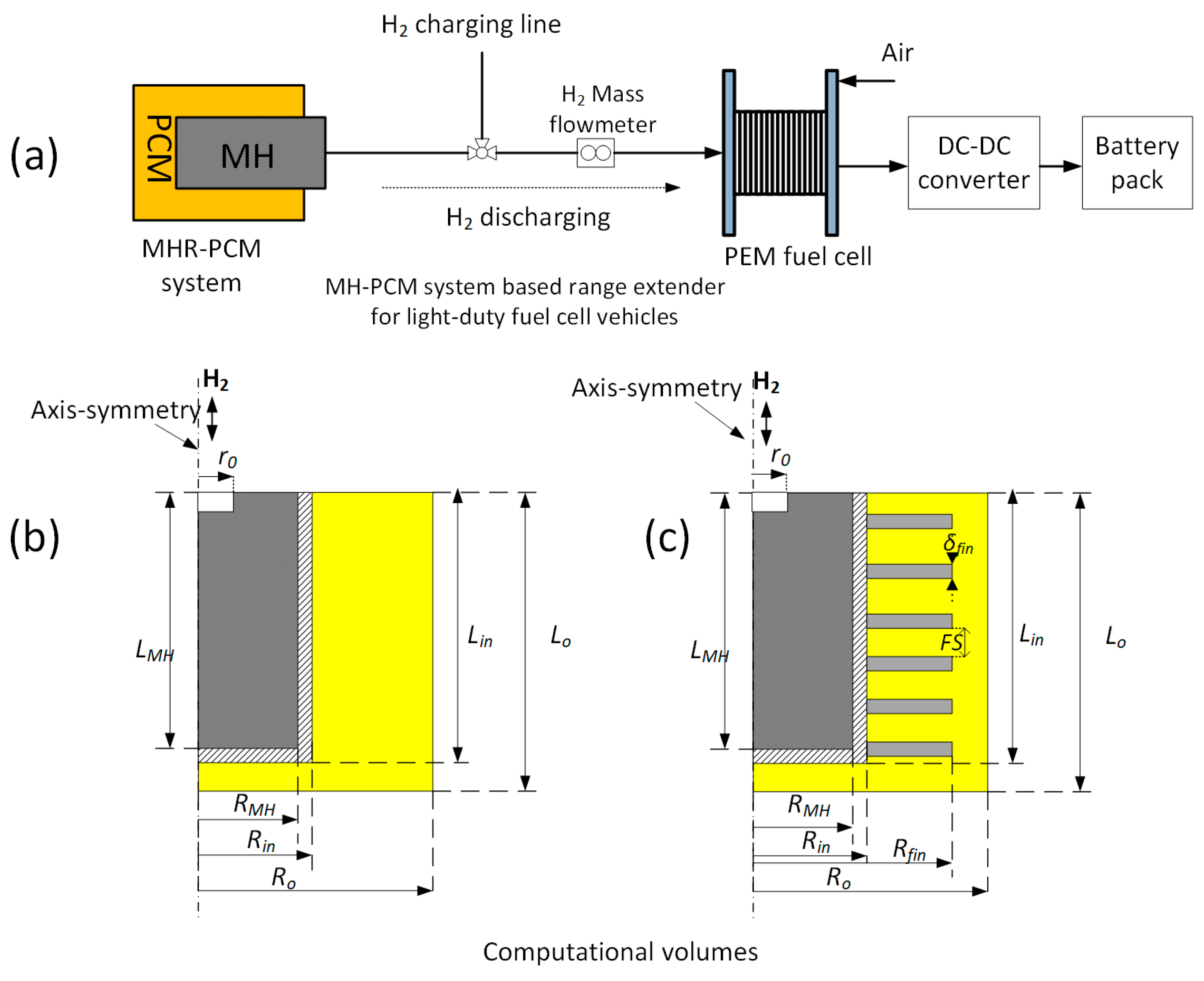
2.1. Problem Description

MHR-PCM systems coupled with a fuel cell are shown in Figure 1a. During the H2 charging, the absorption(exothermic) heat is stored in the PCM, in which case the PCM melts. When power is needed from the fuel cell, hydrogen is discharged from MHR by absorbing (endothermic) the heat stored in the PCM. Therefore, the PCM solidifies in this step. Given the highly transient nature of the hydrogen desorption rate, the fuel cell is not used directly to power the vehicle. Instead, it is connected to a battery. This system acts as a range extender for the given light-duty vehicles. Two designs of MHR-PCM systems are analyzed. Their computational models are provided in Figure 1b,c. The computational model of design A consists of a 2-D axis-symmetry cylindrical reactor of radius RMH = 30 mm and a height of Lin = 400 mm, containing AB2 type hydride materials. The reactor made of structural aluminum (6061-T6) is inserted in an annulus jacket containing paraffin wax PCM, of thickness δpcm = RoRin, with a length Lo = 412 mm. It should be noted the thickness (volume) of PCM should be calculated so that its volumetric energy density matches that of metal hydride [13]. Note that in the literature, this design is the most adopted in the hydrogen storage performance of MHR-PCM systems [13,14,15,16,17,18,27,34].
Design B is the modification of design A whereby to improve the heat transfer inside the PCM, annular fins with the rectangular profile are attached to the external wall of the MH tank. Furthermore, the overall thermal conductivity of the PCM is tuned by varying the volume fraction (length, Lf = RfinRin, and thickness δfin) and the spacing of the fin (FS). In both of the designs, H2 is fed/retrieved through a concentric pipe of radius r0. In this study, the metal hydride used is Ti-based AB2 hydride with the following composition: Ti0.85Zr0.15(FeCrMnNiV)2. This hydride operates at room temperature and has fast kinetics as demonstrated in [31]. Moreover, AB2 type hydrides have been used for several light-duty fuel cells vehicles [31,33,35]. The loading of hydride materials in reactors is an issue that requires a great deal of attention. As it is well known, loose hydride powder brings about a performance deterioration with H2 absorption/desorption cycling. Indeed, the hydride particles refine to nanosize as the number of cycles increases, which leads to a decrease in effective thermal conductivity. To increase the thermal conductivity, reactors equipped with sophisticated internal heat exchangers are designed. However, the loading of a large quantity of loose powder in these sophisticated reactor designs becomes problematic (inert environment, shaker, and compacting using press) [31,33]. Therefore, the mixture of hydride materials with expandable natural graphite or metal foams with high porosity per inch (PPI) can be a simple solution to increase the thermal conductivity and the easy loading inside hollow reactors. The thermophysical properties of this material and aluminum 6061-T6 used in the simulation are listed in Table 1 [31,36,37,38].
Selecting the appropriate PCM for this MH-PCM system should be conducted carefully. There are mainly three types of PCMs, which are organic (paraffin), inorganic (salt hydrates, metallic), and eutectic (combination of PCM). Each type has its pros and cons. For example, paraffin waxes are commonly used as they have high volumetric energy density and are non-corrosive compared to their counterpart salt hydrates. However, here, we will investigate the effect of selecting low-temperature PCM on the dehydrogenation performance of MHR-PCM systems. Table 2 lists the properties of four chosen PCMs belonging to paraffin wax, salt hydrate, and eutectic with the RT35 selected as the base PCM.

2.2. Governing Equations

The following simplifications are made for metal hydride reactors [13,14,16] and PCM:
  • The thermophysical properties of hydride are independent of temperature and concentration.
  • Hydrogen and metal hydrides are in thermal equilibrium.
  • The phase change materials’ thermo-physical properties (density, solid-liquid specific heat, thermal conductivity) are uniform.
  • The bed porosity is constant.
  • The latent heat of phase change is temperature independent.
  • The buoyancy-based natural convection is disregarded as the MHR_PCM is positioned horizontally to minimize the effect of gravity. Also, the presence of fin can reduce the impact of natural convection [39,40].
  • The PCM jacket is perfectly insulated.
There are three types of materials in this system, namely the metal–hydrogen, the PCM, and metallic fins and walls. The local temperature of metal hydride is determined by the conduction and convection energy balance:
( ρ C p ) e f f T M H t + · ( ρ g C p g V T M H ) = λ e f f 2 T M H + ( 1 ε ) M g ρ M H w t d α d t Δ H
The local temperature of the reactor wall and fins is expressed as follows:
( ρ C p ) w / f i n T w / f i n t = λ w / f i n 2 T w / f i n
The local temperature of the PCM reads as follows:
ρ p c m C p , e f f ( T p c m ) T p c m t = λ p c m 2 T p c m
where the effective heat capacity in Equations (1) and (3) is defined as follows:
( ρ C p ) e f f = ε ρ g C p g + ( 1 ε ) ρ M H C p M H
ρ p c m C p , e f f ( T ) = f ρ p c m , l C p , p c m , l + ( 1 f ) ρ p c m , s C p , p c m , s + ρ p c m , l Δ H p c m d f ( T p c m ) d T p c m
The rate of melting fraction is generally defined as a symmetric Gaussian distribution centered in Tm. As a result, the melting fraction is a smoothed Heaviside function [41]:
f = { 0 T p c m < T m Δ T t r / 2 0.5 [ 1 + e r f ( 6 ( T p c m T m ) 2 Δ T t r ) ] T p c m T m Δ T t r / 2
where ΔTtr and Tm are the liquid–solid transition (mushy zone) interval and the melting/freezing temperature (the peak temperature of a PCM’s melting/freezing profile), respectively.
The dynamic of hydrogen density is expressed as:
ε ρ g t + · ( ρ g V g ) = ( 1 ε ) ρ M H w t d α d t
where Darcy’s law defines the hydrogen velocity in the porous hydride bed:
V g = K e f f μ g p
where the permeability Keff of the porous bed depends on the averaged particle size and the bed porosity through the relation of Kozeny–Karman [42] and μg is the dynamic viscosity of hydrogen gas.
The ideal gas law gives the relationship between the pressure and density of the gas:
p = ρ g R g T M H M g
The reaction kinetics of metal hydrides during desorption is described by:
d α d t = k d e x p ( E d R T ) ( p p e q p e q ) ( α α 0 )
where α0 is the residual reacted fraction.
Where the equilibrium pressure is expressed as follows:
ln ( p e q p 0 ) = Δ H R g T M H Δ S R g
The initial and boundary conditions are defined as follows:
At t = 0, T0 = 40 °C (313 K), p0 = 22 bar, αMH = 1, f = 1.
Two types of boundary conditions are considered during the hydrogen desorption from a metal hydride:
H2 pressure condition at the top of the metal hydride bed:
p ( z = L M H ,   0 r r 0 ) = p d e s = 1.5   bar
Constant H2 flow rate (velocity) condition on the top of the MH bed:
V ( z = L M H , 0 r r 0 ) = V 0
where the flowrate is defined as:
Q m = ρ g ( z = L M H ,   0 r r 0 ) π r 0 2 V 0
Conduction/conduction heat continuity between MH and reactor wall:
( λ e f f T M H λ w T w ) · n = 0
Conduction/conduction heat continuity between PCM and reactor wall/fin:
( λ p c m T p c m λ w T w ) · n = 0
( λ p c m T p c m λ f i n T f i n ) · n = 0
The adiabatic (axis-symmetry) boundary condition:
T M H = T p c m = 0

2.3. Numerical Settings and Validation

The multi-physics governing equations are solved in COMSOL using the linear solver PARDISO (parallel direct solver). The flowchart of the selected modules and procedures was given in a previous study [42]. The implicit backward Euler algorithm is used to discretize the time-dependent differential equations, where the default time step of Δt = 0.01 s is adopted. An absolute error of 10−4 was used to ensure the convergence and accuracy of the model. The computational domain was discretized using triangular meshes. The meshes were sufficiently refined to a balance between performance accuracy and computational time. All the simulation work was performed on a personal computer with the following specifications: DELL XPS Intel i7-8700 hexacore (12 threads) CPU @3.20 GHz with 32 Gb of RAM.
This model was already validated in our previous works [9,16,41]; therefore, the reader is referred to these works for model validation to avoid data redundancy.

3. Results and Discussion

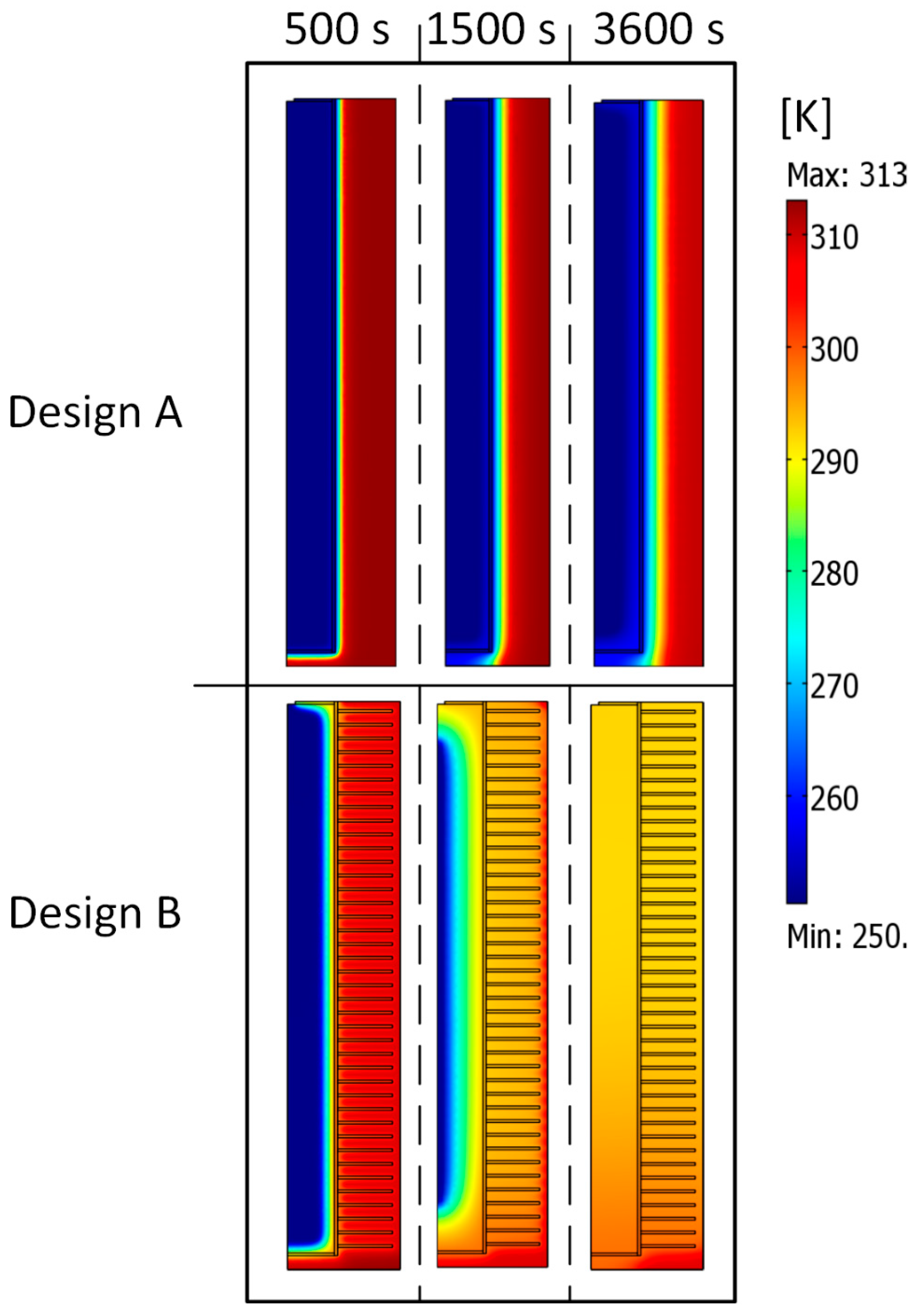
3.1. Designs Comparison

The first step is to compare the two MHR-PCM designs and assess the benefits of adding fins on the dehydrogenation performance. The dimensions of the designs are given in Table 3. For the simulation of H2 desorption, the pressure condition is applied at the exit boundary of the reactor.
Figure 2 shows the comparison of both the designs. As can be seen in Figure 2a, the initial endothermic effect is comparable as the pressure difference at t = 0 is the same. Therefore, the temperature of MH in design A sharply drops to −22 °C, which corresponds to the equilibrium temperature at a pressure of 1.5 bar. However, the MH temperature slowly increases due to poor heat exchange between MH and PCM. As a result, hydrogen is sluggishly depleted (Figure 2b) from the tank for the duration of the process. Its maximum capacity is desorbed after 160 min.
On the contrary, design B exhibits a better H-desorption performance. The reactor is fully depleted from hydrogen in about 28 min. The temperature distribution at three selected times is plotted in Figure 3 to better understand the heat transfer process in both designs. Note that the distributions of reacted fraction and PCM liquid fraction follow the same trends as the temperature one; thus, they can be omitted here. At an early stage of the dehydrogenation process, the temperature of MH is at the lowest (251 K), while that of PCM is at 313 K due to the fast endothermic effect. Then, the temperature changes at the interface between the two regions, the reactor wall. In this case, the interfacial temperature propagates in an L-shaped layer. And as time progresses up to 3600 s, the L-shape layer remains as the heat transfer between both media is poor. Design B shows a uniform temperature distribution after 3600 s due to fins, which dispatch heat from PCM to MH bed. In the rest of the article, design B is subsequently chosen.

3.2. Dehydrogenation Performance under Constant Flowrate Demand (H2 Velocity)

The control of hydrogen-flow demand from MHR-PCM systems is important for a smooth operation of fuel cell placed downstream. This work aims to assess the duration of hydrogen supply to a fuel cell from the MHR-PCM systems. As we mentioned earleir, fuel cells rated at 500–1000 W are suitable for light-duty vehicles applications. These fuel cell powers correspond to fuel demand of 5.5 NL/min (500 W), 8.2 NL/min (750 W), and 12 NL/min (1000 W). Since the hydrogen desorption from MH reactor depends on the heat supply, especially the temperature, here, only the dynamic behavior of H2 flow rate as a function of the thermophysical properties of PCM and the initial temperature of the hydrogen desorption process should be investigated. From a dynamical viewpoint, the hydrogen flowrate Qm is proportional to its density, velocity, and exit-boundary surface as defined in Equation (14).
The H2 desorption simulations were performed under constant H2 flow rates (fuel cell power). Figure 4a shows the temperature profile, and the amount of H2 desorbed from the MH reactor. As the flowrate demand is increased, the MH bed experiences a high endothermic effect. From the figure it can be seen that the lowest temperature (12 °C) in the reactor is reached when the reactor supplied H2 at a flowrate of 12 NL/min. At the same time, the H2 desorption is quickened as the flow rate increases. The heightening of the endothermic effect leads to the decline of hydrogen pressure inside the bed, for which the difference with the equilibrium pressure of MH constitutes the driving force of hydrogen flow outside the MH reactor. From Figure 4b it is seen that the H2 pressure in the reactor decreases rapidly with the increase of H2 flowrate demand. Also, from the figure, one can see the MH reactor can supply H2 at a constant flowrate of 12 NL/min for a duration of 13.2 min; after that, the hydrogen flowrate gradually decreases to 0. This means that MHR-PCM supplies H2 to a 1 kW FC for 13.2 min in this condition. As a result, the hydrogen utilization (22.2%) is quite low as the FC consumes 158.4 NL out of the MH-PCM’s maximum capacity of 712 NL. To improve the H2 utilization, it is recommended to decrease the H2 flowrate demand. Decreasing the flowrate to 8.2 NL/min (750 FC power) or 5.5 NL/min (500 W FC power), the MHR-PCM system can supply hydrogen for 42.2 or 79.7 min with an H2 utilization factor of 48.6% or 61.1%, respectively.
These results are highly optimistic compared to those obtained in a previous study by Davids et al. [31] using the same hydride material. Their experimental findings showed that the MH reactor submitted under forced convection and room temperature (25 °C) could supply hydrogen to a 1 kW FC for 9 min with an H2 utilization ratio of 11%. However, the operation duration could only increase to 21.8 or 48.2 min as the load was decreased to 750 or 500 W, respectively. They pointed out that the forced convection using ambient air was insufficient to sustain the high demand for hydrogen flowrates (5–12 NL/min). In passive heat management using PCM, there are two methods to improve heat transfer: increasing the temperature gradient between the heat source and sink or adding materials with high thermal conductivity. In the next part of this work, we look at ways to increase the H2 supply time at a constant flowrate of 12 NL/min (which corresponds to the feeding of 1-kW fuel cell).

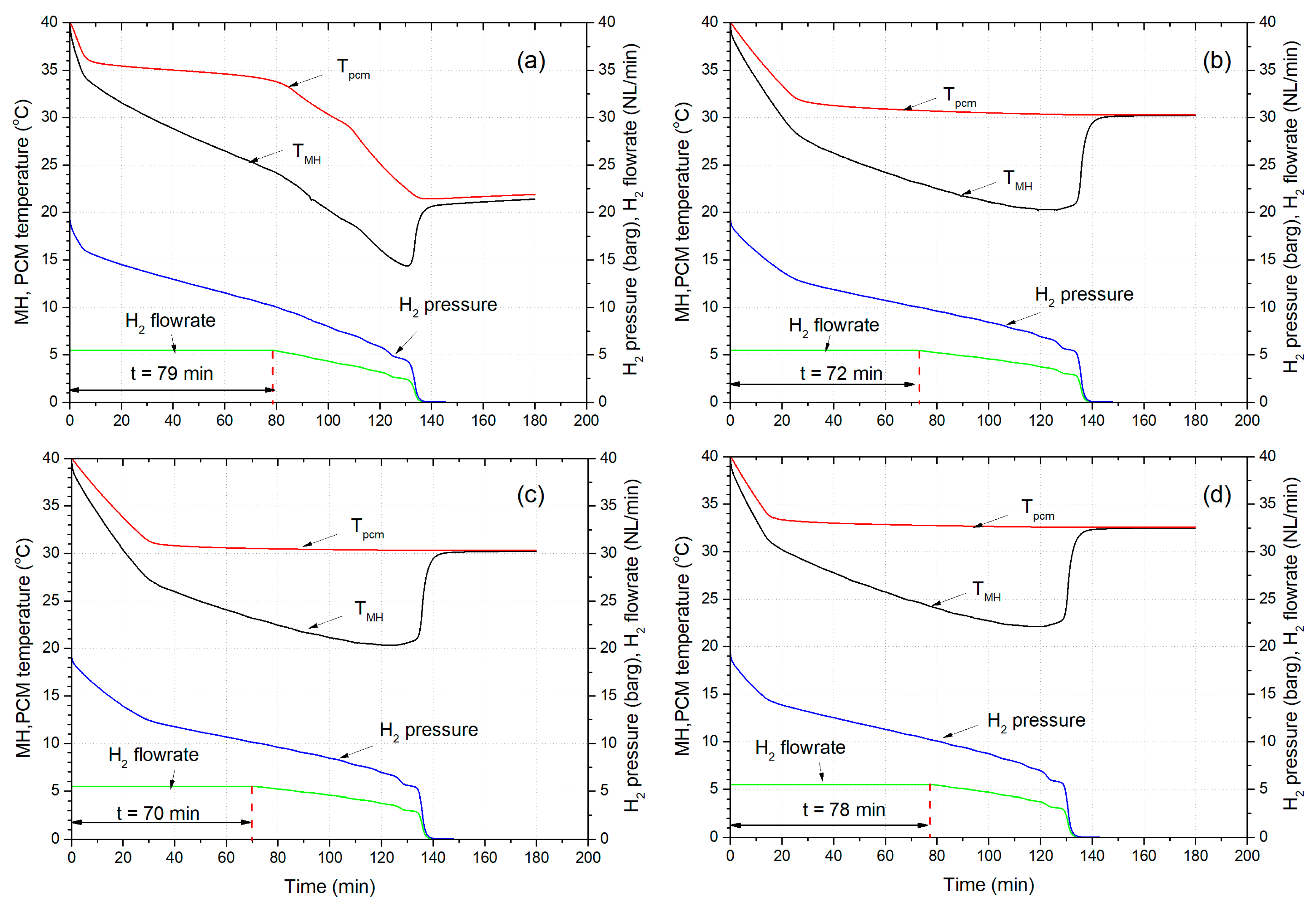
3.3. The Effect of PCM’s Freezing Point on the Dehydrogenation Performance

To study this effect, the initial temperature is fixed at 40 °C for all the cases. Furthermore, the other thermo-physical properties such as density, specific heat, and heat of solidification are kept constant. Figure 5 shows the effect of changing the freezing point of the PCM on the dehydrogenation time. Since temperature gradients drive the metal hydride dehydrogenation performance, the difference between the MH operating temperature and the heat transfer media (PCM) should be high. Therefore, increasing the freezing point of PCM improves the H2 desorption of the MHR. At a low freezing point, first, the MH absorbs the sensible heat of PCM. Since PCM sensible heat is lower than the latent heat, hydrogen desorption slows down. As a result, there is an incubation time before the solidification of PCM. The incubation time decreases from 13 to 7 to 2 min as the freezing point increases from 25 to 30 to 35 °C, respectively. From Figure 5c, the increase of freezing point from 25 to 30 °C reduces the H2 desorption time from 110 to 101 min. A further increase of freezing point to 39 °C results in the decreasing of H2 desorption time to 94 min. The MHR-PCM with a high freezing point of 39 °C supplies hydrogen at a constant flowrate of 12 NL/min for 20 min. This is a high improvement (~42.85%) from the base case of RT35.

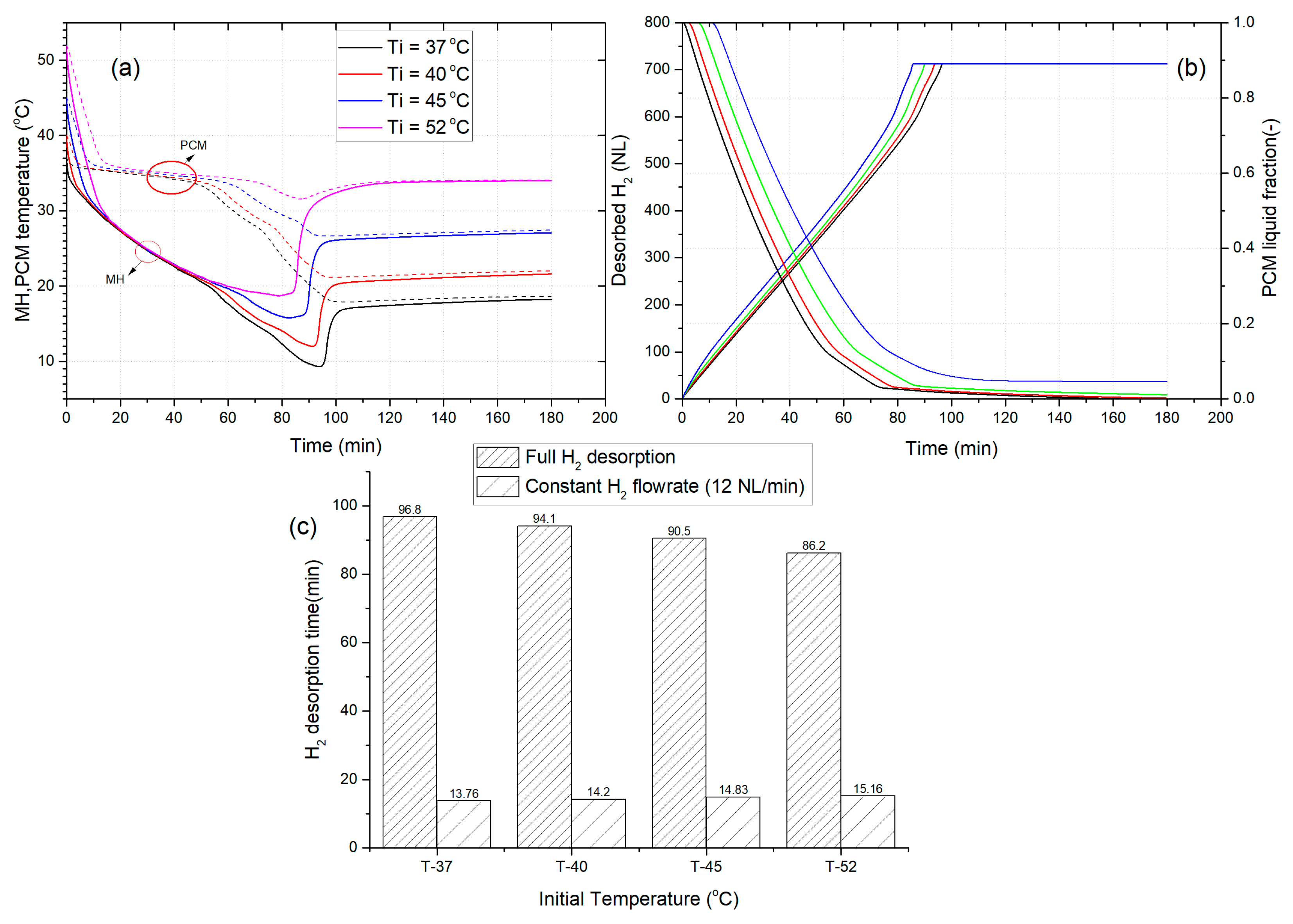
3.4. The Effect of Initial Temperature of MHR-PCM on the Dehydrogenation Performance

Another way to increase the dehydrogenation performance of MHR-PCM system is to raise the initial temperature of the H2 desorption process. Figure 6 depicts the effects of initial temperature on the hydrogen desorption of the MH tank. Increasing the initial temperature only adds some sensible heat to the process at a constant freezing point. Since the sensible heat of PCM is just a small fraction of latent heat, the dehydrogenation time decreases insignificantly as the initial temperature is increased. For example, from Figure 6c the dehydrogenation time decreases by 3 min only when the initial temperature is raised by 5 °C (40 to 45 °C). The improvement effect is annihilated when a constant flow rate of 12 NL/min is required from the MHR. In other words, the increase of initial temperature does not have any impact on the duration of the continuous supply 12 NL/min of hydrogen since the time only varies from 13.7 to 15.1 min.

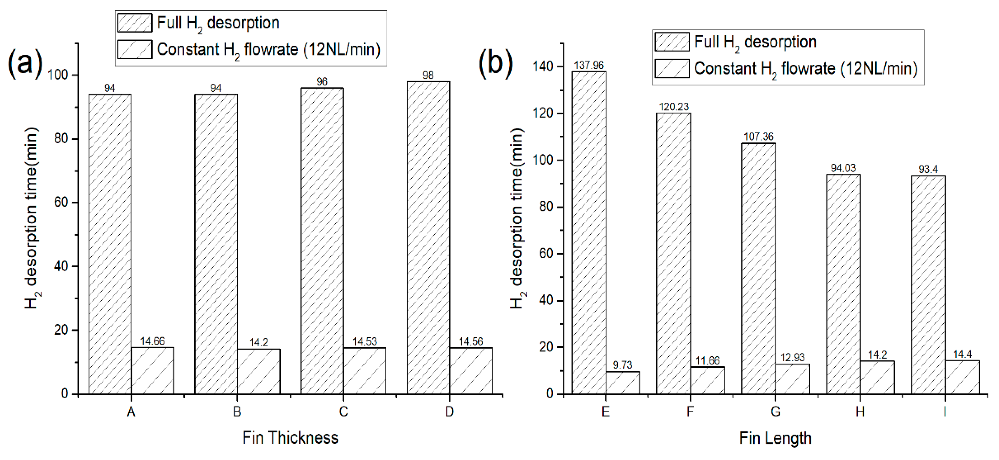
3.5. The Effects of Fin’s Geometrical Parameters on the Dehydrogenation Time

The heat transfer between the PCM and the metal hydride can be improved by modifying the dimension of fins (length and thickness) and their spacing since fins act as heat conveyor pathways. In the previous section, the fin volume faction relative to the PCM jacket volume was fixed to 19% (Lf = 0.035 m, δfin = 0.002 m), and we saw that even with such a high-volume fraction, the metal hydride was able to desorb hydrogen completely. Therefore, changing the fin length or thickness modifies the fin volume fraction, which will change the amount of PCM necessary for complete hydrogen storage.
Figure 7a shows the dependence of H2 desorption time on the fin thickness. As can be seen, increasing the fin thickness from 0.001 to 0.0035 m results in increasing the H2 desorption times from 5638 s (94 min) to 5936 s (98 min). This behavior is not what should be expected as the volume of the fin is increased from 8.69 to 43.67%. Therefore, the heat transfer should be improved. However, one plausible explanation for the increasing dehydrogenation time is that the active material (PCM) is replaced by a passive fin, which only provides sensible heat instead of latent heat.
Moreover, it is seen from the figure that increasing the fin thickness does not improve the time required to supply hydrogen to a 1-kW fuel cell stack. As a result, irrespective of the fin thickness, the MHR-PCM system can only provide the necessary 12 NL/min hydrogen flow rate for a duration of ~14 min. Therefore, the fin thickness does not impact the hydrogen desorption of MHR-PCM systems, albeit it increases the PCM’s effective thermal conductivity.
In contrast, increasing the fin length positively affects the system performance (Figure 7b). For example, as seen in Figure 7b, the increasing fin length from 0.015 to 0.038 m reduces the H2 desorption time from 137 to 93 min, which is a 32.11% improvement. This is because the rise of fin length usually increases the fin surface, which improves the PCM thermal conductivity. In these design conditions, the MHR-PCM systems can provide hydrogen to a 1-kW fuel cell for a duration varying between 9 and 14 min.
From the above results, it is shown that by varying different parameters of the PCM, the MHR could supply H2 at a constant flow rate of 12 NL/min for a duration of 20 min max (effect of the high freezing point). Therefore, using this MHR-PCM systems for a range extender, the maximum energy of a 1-kW fuel cell made available for the battery is 333 Wh. To further improve this supplied energy, it is suggested to decrease the working fuel cell power to enhance the hydrogen utilization of the MHR.

3.6. The Effect of PCM Selection on Dehydrogenation Performance

Figure 8 compares the dehydrogenation performance of MHR-PCM system using different PCMs. The required hydrogen flow rate for the fuel cell is decreased to 5.5 NL/min. In addition, the size of the jacket is fixed. By looking at the temperature of the PCM, it is seen the temperature of the salt hydrates (LiNO3∙3H2O and Na2SO4∙10H2O) and eutectic (SP29Eu) remained uniform close to their respective freezing point. There are two reasons for this behavior; the first one is that salt hydrates and eutectic have a very high latent heat compared to the base PCM RT35 (see Table 2). Secondly, they also have a huge thermal capacity (ρCp) which contributes to sensible heat as can be seen in Figure 9. Note that, the vertical dotted lines emphasize the duration of the sensible heat, prior phase transition of each PCM. As a result, the metal hydride only used a portion of their latent heat. The analysis of the PCMs liquid fraction (Figure 9) shows that these PCMs did not completely solidify (f > 0.5) as the PCM jacket was oversized for the given MHR. Therefore it is suggested to reduce the PCM jacket by half in order to save of PCM materials, thereby the overall cost of the MHR-PCMs. Further studies in that direction should be undertaken in the future.
A constant H2 flow rate was sustained for a long period due to the high difference between the H2 pressure inside the reactor and the exit pressure (1 bar). The MHR-PCM equipped with RT35, LiNO3∙3H2O, Na2SO4∙10H2O, and SP29Eu could provide hydrogen at a uniform flow of 5.5 NL/min for a duration of 79, 70, 78, and 72 min, respectively. These times correspond to an energy produced by the fuel cell and available for the battery of 658, 583.3, 650, and 600 Wh for these PCMs mentioned in the order above.
Finally, given the low density of RT35 compared with other PCMs, its selection for the MHR-PCM system can improve the gravimetric energy storage density and is thus recommended for practical applications.

4. Conclusions

One of the main challenges of using metal hydrides in fuel cell vehicles is the ability of these hydrides to supply hydrogen to fuel cells consistently. The heat supply using forced convection usually solves the problem but decreases overall efficiency. This article investigated the hydrogen desorption dynamics of a metal hydride tank coupled with phase change materials for light-duty PEM fuel cells vehicles. The two-dimensional mathematical model was employed to analyze the effects of the phase change materials’ properties on the hydrogen desorption time and hydrogen flowrate demands. The main conclusions are drawn:
  • The reactor design of the MHR-PCM systems plays a crucial role in their dehydrogenation performance. For example, the H2 desorption time of an MHR-PCM equipped with an annular fin is strongly reduced compared to that of MHR-PCM without fins.
  • For a given initial temperature of the desorption process, the increase of the freezing point can positively improve by up to 42%, the duration of H2 supply at a constant flow rate of 12 NL/min.
  • The PCM thermal conductivity enhancement with the addition of different fin volume fractions either by changing the fin length or thickness (8 to 43.6%) showed little to no improvement in the H2 desorption performance.
  • Finally, among different PCMs such as salt hydrates, paraffin, and eutectic, paraffin wax RT35 showed the best dehydrogenation performance by providing hydrogen to a fuel cell for 79 min. Moreover, the gravimetric energy density for MHR-PCM systems using paraffin is superior to salt hydrates given their low density.
For high flowrate demand, the hydrogen utilization ratio of the MHR-PCM can be improved by a sequential or periodic on/off switch of the fuel cell to allow for heat recovery inside the metal hydride bed. This aspect should be further discussed in our future investigation.

Author Contributions

Conceptualization, S.N.N. and I.T.; methodology, S.N.N.; software, S.N.N. and I.T.; validation, S.N.N.; formal analysis, S.N.N.; writing—original draft preparation, S.N.N. and I.T.; writing—review and editing, S.N.N., I.T. and M.J.G.; funding acquisition, I.T. All authors have read and agreed to the published version of the manuscript.

Funding

S. Nyallang Nyamsi acknowledges the financial incentive from the Department of Science and Technology (DST) in South Africa (project KP6-SO1). I. Tolj and S. Nyallang Nyamsi acknowledge financial support from EU Horizon 2020/RISE project “Hydrogen fueled utility vehicles and their support systems utilizing metal hydrides HYDRIDE4MOBILITY” (project number: 778307).

Institutional Review Board Statement

Not applicable.

Informed Consent Statement

Not applicable.

Data Availability Statement

Not applicable.

Conflicts of Interest

The authors declare no conflict of interest.

Nomenclature

CpHeat capacity (J·kg−1·K−1)
EdActivation energy (J·mol−1)
fPhase change material’s liquid fraction
ΔHReaction heat (J·mol−1 H2), latent heat (J·kg−1)
kdReaction rate constant (s−1)
KPermeability (m2)
LLength (m)
MgH2 molecular weight (kg·mol−1)
pPressure (Pa)
PEMFCProton exchange membrane fuel cell
Q v H2 flow rate (kg·s−1)
RRadius (m)
RgUniversal gas constant (J·mol−1·K−1)
SSurface (m2)
ΔSEntropy change of the reaction (J·mol−1·K−1)
ΔtTime step (s)
ΔTTransition interval/mushy zone (K)
tTime (s)
TTemperature (K)
V Velocity (m·s−1)
wtH2 weight capacity
Greek letters
αReacted fraction
εBed porosity
δFin thickness
λThermal conductivity (W·m−1·K−1)
µDynamic viscosity (Pa·s)
ρDensity (kg·m−3)
Subscript
ddesorption
eqequilibrium
effeffective
finfin
ggas
iinitial
ininner
mMelting/freezing point
MHMetal hydride
pcmPhase change material
oouter
trtransition
wwall

References

  1. Züttel, A. Materials for hydrogen storage. Mater. Today 2003, 6, 24–33. [Google Scholar] [CrossRef]
  2. Zhang, J.; Fisher, T.S.; Ramachandran, P.V.; Gore, J.P.; Mudawar, I. A review of heat transfer issues in hydrogen storage technologies. J. Heat Trans.—Trans. ASME 2005, 127, 1391–1399. [Google Scholar] [CrossRef]
  3. Afzal, M.; Mane, R.; Sharma, P. Heat transfer techniques in metal hydride hydrogen storage: A review. Int. J. Hydrogen Energy 2017, 42, 30661–30682. [Google Scholar] [CrossRef]
  4. Laurencelle, F.; Goyette, J. Simulation of heat transfer in a metal hydride reactor with aluminium foam. Int. J. Hydrogen Energy 2007, 32, 2957–2964. [Google Scholar] [CrossRef]
  5. Mellouli, S.; Dhaou, H.; Askri, F.; Jemni, A.; Ben Nasrallah, S. Hydrogen storage in metal hydride tanks equipped with metal foam heat exchanger. Int. J. Hydrogen Energy 2009, 34, 9393–9401. [Google Scholar] [CrossRef]
  6. Nagel, M.; Komazaki, Y.; Suda, S. Effective thermal-conductivity of a metal hydride bed augmented with a copper wire-net matrix. J. Less-Common Met. 1987, 131, 426. [Google Scholar] [CrossRef]
  7. Mohan, G.; Maiya, M.P.; Murthy, S.S. Performance simulation of metal hydride hydrogen storage device with embedded filters and heat exchanger tubes. Int. J. Hydrogen Energy 2007, 32, 4978–4987. [Google Scholar] [CrossRef]
  8. Askri, F.; Salah, M.B.; Jemni, A.; Nasrallah, S.B. Optimization of hydrogen storage in metal-hydride tanks. Int. J. Hydrogen Energy 2009, 34, 897–905. [Google Scholar] [CrossRef]
  9. Nyamsi, S.N.; Yang, F.S.; Zhang, Z.X. An optimization study on the finned tube heat exchanger used in hydride hydrogen storage system-analytical method and numerical simulation. Int. J. Hydrogen Energy 2012, 37, 16078–16092. [Google Scholar] [CrossRef]
  10. Jensen, J.O.; Vestbø, A.P.; Li, Q.; Bjerrum, N.J. The energy efficiency of onboard hydrogen storage. J. Alloy. Compd. 2007, 446–447, 723–728. [Google Scholar] [CrossRef] [Green Version]
  11. Garrier, S.; Delhomme, B.; de Rango, P.; Marty, P.; Fruchart, D.; Miraglia, S. A new MgH2 tank concept using a phase-change material to store the heat of reaction. Int. J. Hydrogen Energy 2013, 38, 9766–9771. [Google Scholar] [CrossRef]
  12. Mellouli, S.; Ben Khedher, N.; Askri, F.; Jemni, A.; Ben Nasrallah, S. Numerical analysis of metal hydride tank with phase change material. Appl. Therm. Eng. 2015, 90, 674–682. [Google Scholar] [CrossRef]
  13. Darzi, A.A.R.; Afrouzi, H.H.; Moshfegh, A.; Farhadi, M. Absorption and desorption of hydrogen in long metal hydride tank equipped with phase change material jacket. Int. J. Hydrogen Energy 2016, 41, 9595–9610. [Google Scholar] [CrossRef]
  14. Tong, L.; Xiao, J.; Bénard, P.; Chahine, R. Thermal management of metal hydride hydrogen storage reservoir using phase change materials. Int. J. Hydrogen Energy 2019, 44, 21055–21066. [Google Scholar] [CrossRef]
  15. Mâad, H.B.; Miled, A.; Askri, F.; Nasrallah, S.B. Numerical simulation of absorption-desorption cyclic processes for metal hydrogen reactor with heat recovery using phase-change material. Appl. Therm. Eng. 2016, 96, 267–276. [Google Scholar] [CrossRef]
  16. Nyamsi, N.S.; Tolj, I.; Lototskyy, M. Metal hydride beds-phase change materials: Dual mode thermal energy storage for medium-high temperature industrial waste heat recovery. Energies 2019, 12, 3949. [Google Scholar] [CrossRef] [Green Version]
  17. Ye, Y.; Lu, J.; Ding, J.; Wang, W.; Yan, J. Numerical simulation on the storage performance of a phase change materials based metal hydride hydrogen storage tank. Appl. Energy 2020, 278, 115682. [Google Scholar] [CrossRef]
  18. Tong, L.; Yuan, Y.; Yang, T.; Bénard, P.; Yuan, C.; Xiao, J. Hydrogen release from a metal hydride tank with phase change material jacket and coiled-tube heat exchanger. Int. J. Hydrogen Energy 2021, 46, 32135–32148. [Google Scholar] [CrossRef]
  19. Facci, A.L.; Lauricella, M.; Succi, S.; Villani, V.; Falcucci, G. Optimized Modeling and Design of a PCM-Enhanced H2 Storage. Energies 2021, 14, 1554. [Google Scholar] [CrossRef]
  20. Nguyen, H.Q.; Shabani, B. Metal hydride thermal management using phase change material in the context of a standalone solar-hydrogen system. Energy Convers. Manag. 2020, 224, 113352. [Google Scholar] [CrossRef]
  21. Alqahtani, T.; Bamasag, A.; Mellouli, S.; Askri, F.; Phelan, P.E. Cyclic behaviors of a novel design of a metal hydride reactor encircled by cascaded phase change materials. Int. J. Hydrogen Energy 2020, 45, 32285–32297. [Google Scholar] [CrossRef]
  22. Ling, Z.; Chen, J.; Xu, T.; Fang, X.; Gao, X.; Zhang, Z. Thermal conductivity of an organic phase change material/expanded graphite composite across phase change temperature range and a novel thermal conductivity model. Energy Convers. Manag. 2015, 102, 202–208. [Google Scholar] [CrossRef] [Green Version]
  23. Warzoha, R.J.; Weigand, R.M.; Fleischer, A.S. Temperature-dependent thermal properties of a paraffin phase change material embedded with herringbone style graphite nanofibers. Appl. Energy 2015, 137, 716–725. [Google Scholar] [CrossRef]
  24. Zheng, H.; Wang, C.; Liu, Q.; Tian, Z.; Fan, X. Thermal performance of copper foam/paraffin composite phase change material. Energy Convers. Manag. 2018, 157, 372–381. [Google Scholar] [CrossRef]
  25. Erek, A.; Ilken, Z.; Acar, M.A. Experimental and numerical investigation of thermal energy storage with a finned tube. Int. J. Energy Res. 2005, 29, 283–301. [Google Scholar] [CrossRef] [Green Version]
  26. Rathod, M.K.; Banerjee, J. Thermal performance enhancement of shell and tube Latent Heat Storage Unit using longitudinal fins. Appl. Therm. Eng. 2015, 75, 1084–1092. [Google Scholar] [CrossRef]
  27. Yao, J.; Zhu, P.; Guo, L.; Duan, L.; Zhang, Z.; Kurko, S.; Wu, Z. A continuous hydrogen absorption/desorption model for metal hydride reactor coupled with PCM as heat management and its application in the fuel cell power system. Int. J. Hydrogen Energy 2020, 45, 28087–28099. [Google Scholar] [CrossRef]
  28. Lewis, S.D.; Chippar, P. Analysis of heat and mass transfer during charging and discharging in metal hydride-phase change material reactor. J. Energy Storage 2021, 33, 102108. [Google Scholar] [CrossRef]
  29. de Rango, P.; Marty, P.; Fruchart, D. Hydrogen storage systems based on magnesium hydride: From laboratory tests to fuel cell integration. Appl. Phys. A 2016, 122, 126. [Google Scholar] [CrossRef]
  30. Apostolou, D. Assessing the operation and different refuelling cost scenarios of a fuel cell electric bicycle under low pressure hydrogen storage. Int. J. Hydrogen Energy 2020, 45, 23587–23602. [Google Scholar] [CrossRef]
  31. Davids, M.W.; Lototskyy, M.; Malinowski, M.; van Schalkwyk, D.; Parsons, A.; Pasupathi, S.; Swanepoel, D.; van Niekerk, T. Metal hydride hydrogen storage tank for light fuel cell vehicle. Int. J. Hydrogen Energy 2019, 44, 29263–29272. [Google Scholar] [CrossRef]
  32. Hwang, J.J.; Chang, W.R. Characteristic study on fuel cell/battery hybrid power system on a light electric vehicle. J. Power Sources 2012, 207, 111–119. [Google Scholar] [CrossRef]
  33. Lototskyy, M.V.; Davids, M.W.; Tolj, I.; Klochko, Y.V.; Sekhar, B.S.; Chidziva, S.; Smith, F.; Dana Swanepoel, D.; Pollet, B.G. Metal hydride systems for hydrogen storage and supply for stationary and automotive low temperature PEM fuel cell power modules. Int. J. Hydrogen Energy 2015, 40, 11491–11497. [Google Scholar] [CrossRef]
  34. El Mghari, H.; Huot, J.; Tong, L.; Xiao, J.S. Selection of phase change materials, metal foams and geometries for improving metal hydride performance. Int. J. Hydrogen Energy 2020, 45, 14922–14939. [Google Scholar] [CrossRef]
  35. Lototskyy, M.V.; Tolj, I.; Parsons, A.; Smith, F.; Sita, C.; Linkov, V. Performance of electric forklift with low-temperature polymer exchange membrane fuel cell power module and metal hydride hydrogen storage extension tank. J. Power Sources 2016, 316, 239–250. [Google Scholar] [CrossRef]
  36. Visaria, M.; Mudawar, I. Experimental investigation and theoretical modeling of dehydriding process in high-pressure metal hydride hydrogen storage systems. Int. J. Hydrogen Energy 2012, 37, 5735–5749. [Google Scholar] [CrossRef]
  37. Visaria, M.; Issam Mudawar, I.; Pourpoint, T. Enhanced heat exchanger design for hydrogen storage using high-pressure metal hydride: Part 1. Design methodology and computational results. Int. J. Heat Mass Transf. 2011, 54, 413–423. [Google Scholar] [CrossRef]
  38. ASM Material Data Sheet. Available online: matweb.com (accessed on 13 January 2022).
  39. Sharifi, N.; Bergman, T.L.; Faghri, A. Enhancement of PCM melting in enclosures with horizontally-finned internal surfaces. Int. J. Heat Mass Transf. 2011, 54, 4182–4192. [Google Scholar] [CrossRef]
  40. Tay, N.H.S.; Belusko, M.; Castell, A.; Cabeza, L.F.; Bruno, F. An effectiveness-NTU technique for characterising a finned tubes PCM system using a CFD model. Appl. Energy 2014, 131, 377–385. [Google Scholar] [CrossRef]
  41. Nyallang, N.S.; Lototskyy, M.; Tolj, I. Optimal design of combined two-tank latent and metal hydrides-based thermochemical heat storage systems for high-temperature waste heat recovery. Energies 2020, 13, 4216. [Google Scholar]
  42. Nyallang, N.S.; Tolj, I. The Impact of Active and Passive Thermal Management on the Energy Storage Efficiency of Metal Hydride Pairs Based Heat Storage. Energies 2021, 14, 3006. [Google Scholar]
Figure 1. (a) Range extender based on an MHR-PCM system coupled with a PEMFC, (b) computational model of the MHR-PCM jacket: design A, (c) computational model of the finned-MHR-PCM jacket: design B.
Energies 15 02982 g001
Figure 2. Comparison of dehydrogenation dynamics between the designs A and B. (a) average temperature; (b) reacted and PCM liquid fraction.
Energies 15 02982 g002
Figure 3. Temperature contours in the two designs at different times.
Energies 15 02982 g003
Figure 4. Dynamic behavior of hydrogen desorption from MHR-PCM under constant hydrogen velocity (flowrate): (a) average bed temperature and H2 volume desorbed, (b) H2 gauge pressure and flowrate.
Energies 15 02982 g004
Figure 5. (a) Temporal variation of the average MH and PCM temperature, (b) temporal profile of PCM liquid fraction and the H2 volume desorbed (dotted lines mark the time required for the completion of dehydrogenation process), and (c) dehydrogenation time.
Energies 15 02982 g005
Figure 6. The effect of initial temperature (a) temporal variation of the average MH and PCM temperature, (b) temporal profile of PCM liquid fraction and the H2 volume desorbed, and (c) dehydrogenation time.
Energies 15 02982 g006
Figure 7. (a) effect of fin thickness on the dehydrogenation time (A: δfin = 0.001 m, B: δfin = 0.002 m, C: δfin = 0.003 m, D: δfin = 0.0035 m), (b) effect of fin length on the dehydrogenation time (E: Lf =0.015 m, F: Lf =0.02 m, G: Lf =0.025 m, H: Lf =0.035 m, I: Lf = 0.038 m).
Energies 15 02982 g007
Figure 8. Temporal variation of PCM and MH bed temperature, H2 gauge pressure and flowrate for different PCMs properties: (a) RT35, (b) SP29Eu, (c) LiNO3∙3H2O, and (d) Na2SO4∙10H2O.
Energies 15 02982 g008
Figure 9. Temporal profile of PCMs liquid fraction.
Energies 15 02982 g009
Table 1. Thermophysical properties of AB2-type hydride and reactor wall.
Ti0.85Zr0.15(FeCrMnNiV)2 [31,36,37]Al (6061-T6) [38]
Heat of reaction/kJ/mol26.62-
Entropy change/J/mol/K109.69-
Activation energy, des/kJ/mol16.5-
Rate constant, des/s−1300-
Packed density/kg/m331002700
Specific heat/J/kg/K500897
H2 capacity/wt.%1.5-
Effective thermal conductivity/W/mK1.5166
Bed permeability/m21.3 × 10−12-
Dynamic viscosity/Pa∙s8.4 × 10−6-
Table 2. The thermophysical properties of selected phase change materials [13,34].
Parameter/UnitRT35LiNO3∙3H2ONa2SO4∙10H2ORT(SP29Eu)
Density: solid–liquid/kg/m3880–602140–17801485–14202000
Freezing Point/°C34–3530–3132.5–33.529–30
Latent heat/kJ/kg170296251175
Heat capacity: solid–liquid/J/(kg K)1800–24001730–27701440–25702500
Thermal conductivity: solid–liquid/W/(m K)0.24–0.201.32–0.581.23–0.540.6
Table 3. Size parameters of the two MHR-PCM designs.
Parameters/UnitDesign ADesign B
MH reactor, RMH/m0.030.03
MH reactor height, Lin/m0.40.4
Wall thickness, RinRMH/m0.0020.002
PCM thickness, RoRin/m0.040.04
PCM height, Lo/m0.4120.412
Fin length, Lfin/m-0.035
Fin spacing, FS/m-0.01
Fin thickness, δfin/m-0.002
H2 filter radius, r0/m0.0050.005
Publisher’s Note: MDPI stays neutral with regard to jurisdictional claims in published maps and institutional affiliations.

