Article

Efficiency Analytical Characterization for Brushless Electric Drives

Department of Electrical Engineering and IT, University of Naples Federico II, 80125 Naples, Italy
*
Author to whom correspondence should be addressed.
Energies 2022, 15(8), 2963; https://doi.org/10.3390/en15082963
Submission received: 14 March 2022 / Revised: 11 April 2022 / Accepted: 17 April 2022 / Published: 18 April 2022

Abstract

:
The paper is focused on the formalization of an experimental procedure aimed to characterize the efficiency behaviour of a Permanent Magnet Synchronous Motor-based drive. The characterization is intended to expose the analytical behaviour of the system efficiency by the actual operating condition assigned through torque/speed value. The availability of such a relation in a simple analytical form would allow for real-time adjustment by advanced power management strategies to maximize the whole system efficiency. The proposed method is based on a defined set of measures corresponding to several drive operating conditions. A straightforward elaboration procedure is then formulated with the aim to quantify the different parameters, which intervene in the efficiency characterization. The method has been applied on a 155 kW drive. The results show that good accuracy is achieved while keeping the analytical approach relatively simple.

1. Introduction

In recent years, the role of electric drives in transportation applications has gained increasing attention both in the scientific community and in several industrial fields. The main driving force for this transition is the desired achievement of a significant reduction of climate-altering emissions. In 2021, for example, CO2 concentration was about 411   p p m v above the natural amount 180/300 ppmv. The use of fossil-based fuels in many applications is the main cause. The commitment to reduce climate-altering gases pushes towards an exponential growth of green mobility, with particular reference to electric vehicles (EVs). It has been estimated that the number of ZEV (zero emissions electric vehicles) is expected to reach a market share of 30% in 2030, according to [1].
Nowadays, the major challenge for electric road transportation is the reduced autonomy (if compared to traditional fossil-fuel based systems) of the electric energy storage system (ESS). In this context, it is crucial to maximize the total efficiency in all operating conditions [2]. This objective can be fulfilled by both exploiting optimal control strategies on the motor side [3,4,5] and on the driver side [6,7]. On the other hand, a key role can be played by the power management strategy; indeed, equivalent operating conditions can be obtained by properly regulating the power flows exchanged between the components of the system [8,9]. Depending on the architecture complexity, several freedom degrees may be available to the power strategy. Consequently, the status of the system can be fully characterized only after imposing proper constraints. Objective functions which exploit the freedom degrees by optimizing the efficiency can be fully deployable once the analytical behaviour of the all components is provided [10].
Several approaches have been proposed in literature for the determination of the efficiency of either an electric motor or an electric drive. The most accurate ones involve extended measures on the target system such as the IEEE 112 and the IEC-60034-2-1 standardized procedures [11,12], tailored for induction motors, and the IEEE 1812 and the IEC 61800-9-2 [13,14] standardized procedures, tailored for synchronous motors; other viable approaches developed specifically for PMSM motors are based on the indirect efficiency estimation through either the axis inductance measurements [15] or the so-called stand still test [16], or the exploitation of advanced calculation methods such as the neural networks [17]. In [18], the authors developed an accurate procedure of the efficiency characterization of PMSM, although the method requires a set of measures with the rotor removed, which in most cases is not a viable option.
This paper proposes a straightforward procedure to characterize the relation between the efficiency of a brushless electric drive and its operating point through the formalization of a simple analytical expression based on a reasonable set of measurements. The conceived method is able to separate the converter losses from the motor ones without requiring voltage transducers on the converter outputs. The resulting efficiency function can then be processed by the power management strategy in order to maximize the whole system efficiency.

2. Configuration of the Brushless Electric Drive

The typical configuration of an AC brushless-based hybrid/full-electric drive system for transportation is built upon the proper connection of the following components:
The three phase AC Permanent Magnet Synchronous Machine (PMSM);
The three phase DC/AC Voltage Source Converter (VSC);
The Energy Storage System (ESS), built upon the series/parallel connection of a proper number of electrochemical cells and the correspondent Battery Management System (BMS);
The mechanical power transmission components needed to interface the electric machine to the remaining core elements of the traction system;
The low-level controller of the brushless drive;
The high-level controller of the whole system, i.e., the power management unit.
The paper is focused on the efficiency characterization of the PMSM drive, i.e., the subsystem defined by the PMSM and the VSC, which is the core of the whole transportation drive. Generally, the following losses are generated in the PMSM drive:
VSC conduction losses;
VSC switches losses;
PMSM iron losses;
PMSM joule losses;
PMSM mechanical losses.
A typical PMSM designed for a traction application is characterized by a mechanical rated speed in the range 3000–9000 rpm and a significant number of poles (between eight and 16). Consequently, the rated frequency of the machine is substantially higher than the industrial ones (50/60 Hz). In this context, the major contribution to the total drive losses is given by the iron ones. Therefore, in order to keep the system efficiency at reasonable levels, the increase of the iron losses with the frequency has to be properly contained. This result can be achieved by minimizing the stator eddy currents through further reducing the ferromagnetic sheets with respect to standard designs.

3. Proposed Procedure for Efficiency Analytical Characterization

In order to characterize analytically the efficiency behaviour of the considered system, a set of operating points has to be built upon the following measures:
Motor average speed ω r
Motor available average torque T e
DC-Link average voltage V d c
DC-Link average current I d c
AC rms current I a c
Motor windings temperature ϑ
Each operating point is characterized by the couple ω r , T e . By varying ω r , T e in two independent ranges ( ω r , min , ω r , max ) and ( T e , min , T e , max ), it is possible to extrapolate the function η ω r , T e which links the system efficiency η to the operating point ω r , T e .
By denoting with ω r k and T e r , respectively, the speed and torque series, the following relation applies:
P t r , k = P i r , k P o r , k P j r , k
where P t r , k is the total power losses minus the stator joule power losses, P i r , k is the input power, P o r , k is the output power and P j r , k is the stator joule power losses. Naturally, the power terms can be evaluated as:
P i r , k = V d c r , k I d c r , k P o r , k = T e r ω r k P j r , k = 3 R s 1   + α   ϑ r , k 20   I a c r , k 2
where R s is the phase stator resistance at 20 °C and α is the temperature coefficient of the stator winding conductor. The variation of R s linked to skin/proximity effects is neglected. R s is measured before the test and then reported to 20 °C based on the actual ambient temperature.
At each speed ω r k it is possible to consider the function P t k I a c which links the power term P t to the AC current I a c . It is reasonable to approximate P t k I a c with a quadratic behaviour since:
The conduction power losses in the converter depend on I a c 2
The switching power losses in the converter vary linearly with I a c
The stator iron losses driven by armature reaction depend on I a c 2
Therefore, the following relation is considered:
P t k I a c = P t , 0 k + P t , 1 k I a c + P t , 2 k I a c 2
where the polynomial coefficients P t , 0 k , P t , 1 k , P t , 2 k are quantified by minimizing the mean square error λ k between the continuous function P t k I a c evaluated in I a c r , k and the series P t r , k :
λ k = r P t r , k P t k I a c r , k 2
The power loss term P t , 0 k refers to the iron losses driven by the permanent magnets’ density flux and the mechanical losses (mainly linked to the rolling bearings). From the series P t , 0 k , the corresponding continuous function P t , 0 ω r can be derived once reasonable behaviour is supposed. Since the mechanical losses depend linearly on ω r while the iron losses are a quadratic function of ω r , the following expression is attributed to P t , 0 ω r :
P t , 0 ω r = P t , 0 , 1   ω r + P t , 0 , 2   ω r 2
It should be noted that P t , 0 , 1 refers to both the mechanical losses component and the iron losses component (the contribution driven by the magnetic hysteresis), while P t , 0 , 2 is related to only the iron losses driven by the eddy currents. P t , 0 , 1 and P t , 0 , 2 are found by minimizing the mean square error ε between the continuous function P t , 0 ω r and the series P t , 0 k :
ε = k P t , 0 k P t , 0 ω r 2
The quantification of the ratio of the iron losses versus the mechanical ones would allow to better characterize the trend of the total losses with the variation of the speed and the current; indeed, while the mechanical losses are constant with the motor currents, the iron ones depend on them through the armature reaction. However, the identification of the mechanical losses could be performed only by a full (and therefore irreversible) demagnetization of the permanent magnets. Additionally, an actual demagnetization would require the stator and rotor flux density fields to have the same spatial behaviour; this aspect is far from verified in practical cases. Therefore, the problem of the quantification of the two rates cannot be approached analytically. An acceptable approximation can be achieved once the typical values associated to the bearing losses are taken into account. In particular, the typical ratio of the mechanical losses versus the electric machine rated power is in the range 0.001–0.005%, while, for high frequency application, the correspondent weight of the iron losses is in the range 3–5%. Consequently, the contribution of the mechanical losses to P t , 0 , 1 is just a fraction of that of the iron losses. Therefore, it is reasonable to assume:
P f e , 0 , 1 ω r = β P t , 0 , 1 ω r P m ω r = 1 β P t , 0 , 1 ω r
where β is the ratio of the iron losses term P f e , 0 , 1 with respect to P t , 0 , 1 . The coefficient β is usually in the range 0.95–1; consequently, an error in the coefficient selection does not produce an appreciable deviation in the whole procedure given that the mechanical loss term P m is significantly smaller than the iron loss one [19]. As a consequence, the total iron losses at zero current can be expressed as:
P f e , 0 ω r = β   P t , 0 , 1   ω r + P t , 0 , 2   ω r 2
The dependence of the iron losses on the stator currents can be derived by properly including the armature reaction:
P f e ω r , I a c = Φ 2 + 2 L 2 I a c 2 Φ 2 β   P t , 0 , 1   ω r + P t , 0 , 2   ω r 2
where Φ is the permanent magnets’ flux and L is the stator phase inductance.
The characterization of converter power loss series P c r , k can be performed as:
P c r , k = P t r , k P f e ω r k , I a c r P m ω r k
For each speed ω r k , the coefficient of the correspondent continuous function P c k I a c = P c , 1 k I a c + P c , 2 k I a c 2 can be quantified by minimizing the mean square error γ k with respect to the series P c r , k :
γ k = k P c r , k P c k I a c r 2
Finally, the following relation is assigned to the continuous function P c ω r I a c :
P c ω r , I a c = P c , 1 ω r I a c + P c , 2 ω r I a c 2
where
P c , 1 ω r = P c , 1 h + P c , 1 h + 1 P c , 1 h ω r h + 1 ω r h ω r ω r h P c , 2 ω r = P c , 2 h + P c , 2 h + 1 P c , 2 h ω r h + 1 ω r h ω r ω r h   with   ω r h ω r < ω r h + 1
The linear interpolation approach used to extrapolate the coefficient speed behaviour is justified since the converter power losses do not change significantly with the motor speed.
Finally, the total power losses can be expressed as:
P t o t ω r , I a c = P c ω r , I a c + P f e ω r , I a c + P m ω r + 3 R s 1   + α   ϑ 20 I a c 2
Once the total power losses have been characterized by the previous relation, the efficiency can be analytically formalized through the following:
η ω r , I a c = P L ω r , I a c P L ω r , I a c + P t o t ω r , I a c
where P L is the mechanical power transferred to the load. P L can be computed as:
P L ω r , I a c = T e ω r , I a c ω r
The load available-electromagnetic torque T e can be derived from the total electromagnetic torque T e , t o t by means of:
T e ω r , I a c = T e , t o t I a c P f e , 0 ω r + P m ω r ω r
It is easy to verify that the mechanical power losses are a linear function of the motor speed [20]. On the other hand, the iron power losses driven by the magnets’ flux density are a quadratic function of the speed [21]; however, in the context of the considered application, the motor design is constrained to the minimization of the iron loss quadratic term which otherwise would affect unacceptably the system efficiency at high frequency/speed operation. Under these positions, it is possible to approximate T e as:
T e ω r , I a c T e , t o t I a c T f e , m = T e I a c
where T f e , m is the constant friction torque which approximates the effects of the mechanical and iron loss terms. This relationship states that, under the considered hypothesis, the load available torque is not dependent on the motor speed. Therefore, the corresponding inverse function I a c T e can be characterized at any speed. By conferring to I a c T e the following expression:
I a c T e = I a c , 0 + I a c , 1 T e + I a c , 2 T e 2
a minimum mean square error approach is applied to the quantity:
μ = r I a c r , k ¯ I a c T e r , k ¯ 2
in order to identify the current coefficients.
Finally, the efficiency is quantified as:
η ω r , T e = ω r T e ω r T e + P t o t ω r , I a c T e

4. Experimental Results

The proposed procedure has been applied to an experimental setup in order to confirm the accuracy of the simplified analytical relations derived in the previous section. The employed setup refers to a 155 kW PMSM driven by a 299 kVA inverter; the main correspondent characteristics are reported in the Table 1.
The DC-Link of the inverter was kept to 700 V in the whole test through a 320 kVA/400 V/50 Hz three-phase active rectifier. The motor was mechanically coupled with a 200 kW IM drive through the flange torque meter HBM T10F001R. Two current probes Fluke 378 FC were used to measure the average value of the DC-Link current and the RMS value of one motor phase-current. The rotor speed, the stator winding temperature and the DC-Link voltage were monitored through the PMSM drive software. The different operating points were set by controlling the PMSM drive in torque mode and the IM drive in speed mode. In particular, the working speed was set by the IM, which was kept in break operation, while the working torque was set by the PMSM, which was kept in motor operation; therefore, the rotation speed and the electromagnetic torque could be independently set. The PMSM drive was controlled with a Maximum Torque Per Ampere (MTPA) strategy at each operating condition.
The following quantities were acquired at each operating point:
average value of available torque T e
average value of rotational speed in rpm
RMS value of the AC phase current I a c
average value of the DC-Link voltage V d c
average value of the DC-Link current I d c
temperature of the motor windings ϑ
Several operating points were considered. In particular, the reference speed was changed in the range 500–7000 rpm with a 500 rpm step; at each considered speed, the torque was modified in the range 0.2 p.u.–1 p.u. with a 0.1 p.u. step. Therefore, 135 operating points were characterized. On the basis of the acquired data, the proposed evaluation procedure was implemented in order to identify all the parameters of the efficiency analytical function. Table 2 shows the values found for the relevant quantities.
The effectiveness of the conceived approach has been verified by comparing at each considered operating point the measured efficiency (see Figure 1) with the one computed (see Figure 2) through the formalized analytical function.
Finally, Figure 3 shows the efficiency error behaviour as a function of the motor speed and the available torque.
In this context, the accuracy of the proposed method can be synthetically represented by means of the correspondent mean quadratic error. The value of the computed error (<1.5%) confirms the appropriateness of the simplified method.
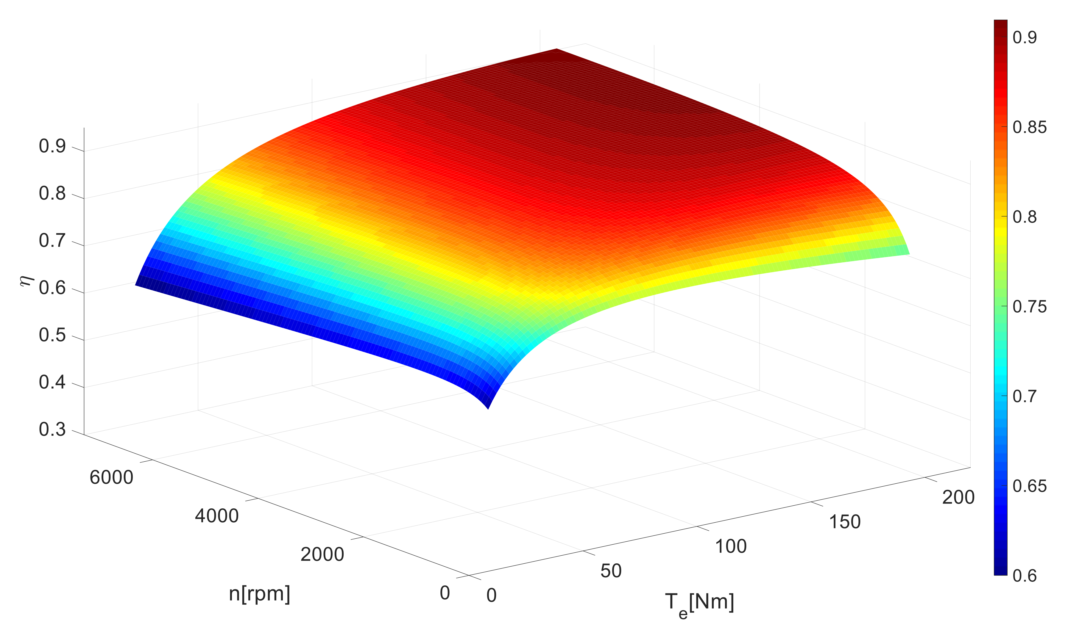
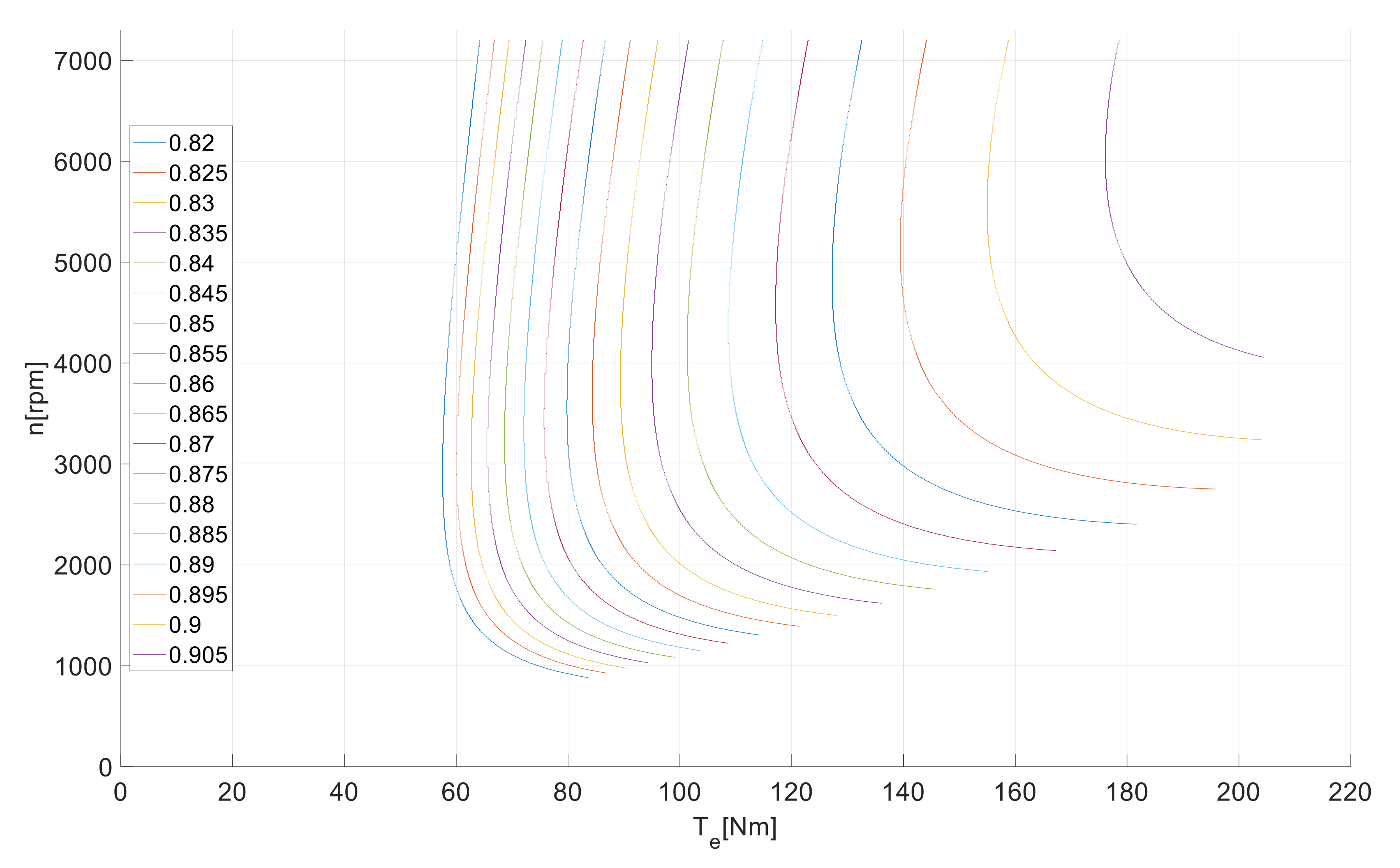
Once the accuracy of the proposed method is verified, it is acceptable to exploit the formalized analytical expression of the system efficiency to extrapolate the results in the rated operating range. Figure 4 and Figure 5 depict the system efficiency surface and the efficiency isocurves with respect to the rated speed range.

5. Conclusions

A straightforward procedure to analytically characterize the efficiency behaviour of a PMSM drive has been presented. The proposed method requires a measurement campaign intended to build a minimum set of operating conditions. The acquired data is then processed in order to assign the parameters to which the efficiency function has been constrained. Indeed, based on the analysis of the main characteristics of the electrical drive, careful approximation allowed to define a simple reference structure for the target efficiency function. Consequently, the resulting identification process is kept relatively simple. The approach was validated by means of an experimental setup based on 155 kW PMSM drive. In particular, the analytical characterization allowed a quick derivation of the system efficiency whole map, which has been extrapolated based on a subset of operating conditions. The good accuracy of the procedure was validated by quantifying the error (always below 2%) between the measured efficiency values and the ones given by the built analytical function.

Author Contributions

The authors contributed to the drafting of the proposed paper in the following way: conception, design of the work and data analysis, G.B. and A.D.; drafting article and critical revision of the article, A.D.P. All authors have read and agreed to the published version of the manuscript.

Funding

This research received no external funding.

Institutional Review Board Statement

Not applicable.

Informed Consent Statement

Not applicable.

Data Availability Statement

Not applicable.

Conflicts of Interest

The authors declare no conflict of interest.

Nomenclature

α the temperature coefficient of the stator winding conductor
η ω r , T e System efficiency function
ϑ Motor windings temperature
Φ Permanent magnets flux
ω r Motor average speed
ω r k Motor speed series
I d c DC-Link average current
I a c AC rms current
I a c , 0 ,   I a c , 1 ,   I a c , 2 Polynomial coefficients
LStator phase inductance
P c Converter power losses
P c , 1 ,   P c , 2 Polynomial coefficients
P f e , 0 Total iron losses at zero current
P i Input power
P j Stator joule power losses
P L mechanical power transferred to the load
P m Mechanical losses
P o Output power
P t Total power losses
P t , 0 ,   P t , 1 ,   P t , 2 Polynomial coefficients
R s the phase stator resistance at 20 °C
T e Motor available average torque
T e r Motor torque series
V d c DC-Link average voltage
r Superscript to indicate the evaluation in a rth point of the motor torque series
k Superscript to indicate the evaluation in a kth point of the motor speed series

References

  1. International Energy Agency (IEA). Global EV Outlook 2018. Towards cross-model electrification. In Electric Vehicles Initiative; IEA Publications: Paris, France, 2018; pp. 143–144. [Google Scholar]
  2. De Almeida, A.T.; Ferreira, F.J.T.E.; Baoming, G. Beyond Induction Motors—Technology Trends to Move Up Efficiency. In Proceedings of the IEEE Transactions on Industry Applications, Stone Mountain, GA, USA, 30 April–3 May 2013; Volume 50, pp. 2103–2114. [Google Scholar] [CrossRef]
  3. Ni, R.; Xu, D.; Wang, G.; Ding, L.; Zhang, G.; Qu, L. Maximum Efficiency Per Ampere Control of Permanent-Magnet Synchronous Machines. In IEEE Transactions on Industrial Electronics; IEEE: New York, NY, USA, 2015; Volume 62, pp. 2135–2143. [Google Scholar]
  4. Balamurali, A.; Feng, G.; Lai, C.; Loukanov, V.; Kar, N.C. Investigation into variation of permanent magnet synchronous motor-drive losses for system level efficiency improvement. In Proceedings of the IECON 2017—43rd Annual Conference of the IEEE Industrial Electronics Society, Beijing, China, 29 October–1 November 2017; pp. 2014–2019. [Google Scholar]
  5. Lee, J.; Nam, K.; Choi, S.; Kwon, S. Loss-Minimizing Control of PMSM With the Use of Polynomial Approximations. In Proceedings of the IEEE Transactions on Power Electronics, Edmonton, AB, Canada, 5–9 October 2008; Volume 24, pp. 1071–1082. [Google Scholar]
  6. Deng, W.; Zhao, Y.; Wu, J. Energy Efficiency Improvement via Bus Voltage Control of Inverter for Electric Vehicles. In IEEE Transactions on Vehicular Technology; IEEE: New York, NY, USA, 2017; Volume 66, pp. 1063–1073. [Google Scholar]
  7. Zhang, C.; Guo, Q.; Li, L.; Wang, M.; Wang, T. System Efficiency Improvement for Electric Vehicles Adopting a Permanent Magnet Synchronous Motor Direct Drive System. Energies 2017, 10, 2030. [Google Scholar] [CrossRef] [Green Version]
  8. Martinez, C.M.; Hu, X.; Cao, D.; Velenis, E.; Gao, B.; Wellers, M. Energy Management in Plug-in Hybrid Electric Vehicles: Recent Progress and a Connected Vehicles Perspective. In IEEE Transactions on Vehicular Technology; IEEE: New York, NY, USA, 2017; Volume 66, pp. 4534–4549. [Google Scholar] [CrossRef] [Green Version]
  9. Wang, X.; He, H.; Sun, F.; Sun, X.; Tang, H. Comparative Study on Different Energy Management Strategies for Plug-In Hybrid Electric Vehicles. Energies 2013, 6, 5656–5675. [Google Scholar] [CrossRef]
  10. Du, A.; Chen, Y.; Zhang, D.; Han, Y. Multi-Objective Energy Management Strategy Based on PSO Optimization for Power-Split Hybrid Electric Vehicles. Energies 2021, 14, 2438. [Google Scholar] [CrossRef]
  11. De Almeida, A.T.; Ferreira, F.J.T.E.; Duarte, A.Q. Technical and Economical Considerations on Super High-Efficiency Three-Phase Motors. In Proceedings of the IEEE Transactions on Industry Applications, Stone Mountain, GA, USA, 30 April–3 May 2013; Volume 50, pp. 1274–1285. [Google Scholar] [CrossRef]
  12. Dambrauskas, K.; Vanagas, J.; Zimnickas, T.; Kalvaitis, A.; Ažubalis, M. A Method for Efficiency Determination of Permanent Magnet Synchronous Motor. Energies 2020, 13, 1004. [Google Scholar] [CrossRef] [Green Version]
  13. IEEE. IEEE Trial-Use Guide for Testing Permanent Magnet Machines in IEEE Std 1812–2014; IEEE: New York, NY, USA, 2015; pp. 1–56. [Google Scholar] [CrossRef]
  14. IEC 61800-9-2. Adjustable Speed Electrical Power Drive Systems. March 2017. Available online: https://webstore.iec.ch/publication/31527 (accessed on 18 February 2022).
  15. Popescu, M.; Dorrell, D. A method for determining ipm motor parameters from simple torque test data. In Proceedings of the IECON 2013—39th Annual Conference of the IEEE Industrial Electronics Society, Vienna, Austria, 10–13 November 2013; pp. 7290–7294. [Google Scholar] [CrossRef]
  16. Candelo-Zuluaga, C.; Riba, J.-R.; Garcia, A. PMSM Torque-Speed-Efficiency Map Evaluation from Parameter Estimation Based on the Stand Still Test. Energies 2021, 14, 6804. [Google Scholar] [CrossRef]
  17. Puron, L.D.R.; Neto, J.E.; Fernández, I.A. Neural networks based estimator for efficiency in VSI to PWM of induction motors drives. In Proceedings of the 2016 IEEE International Conference on Automatica (ICA-ACCA), Curico, Chile, 19–21 October 2016; pp. 1–8. [Google Scholar] [CrossRef]
  18. Deusinger, B.; Lehr, M.; Binder, A. Determination of efficiency of permanent magnet synchronous machines from summation of losses. In Proceedings of the 2014 International Symposium on Power Electronics, Electrical Drives, Automation and Motion, Ischia, Italy, 18–20 June 2014; pp. 619–624. [Google Scholar] [CrossRef]
  19. Urasaki, N.; Senjyu, T.; Uezato, K. Influence of all losses on permanent magnet synchronous motor drives. In Proceedings of the 2000 26th Annual Conference of the IEEE Industrial Electronics Society. IECON 2000. 2000 IEEE International Conference on Industrial Electronics, Control and Instrumentation. 21st Century Technologies, Nagoya, Japan, 22–28 October 2000; Volume 2, pp. 1371–1376. [Google Scholar] [CrossRef]
  20. Dabala, K. Analysis of mechanical losses in three-phase squirrel-cage induction motors. In Proceedings of the ICEMS’2001. Proceedings of the Fifth International Conference on Electrical Machines and Systems (IEEE Cat. No.01EX501); Shenyang, China, 18–20 August 2001, Volume 1, pp. 39–42. [CrossRef]
  21. Yang, G.; Zhang, S.; Zhang, C. Analysis of Core Loss of Permanent Magnet Synchronous Machine for Vehicle Applications under Different Operating Conditions. Appl. Sci. 2020, 10, 7232. [Google Scholar] [CrossRef]
Figure 1. Interpolated surface of the measured system efficiency based on experimental data as a function of torque and speed.
Energies 15 02963 g001
Figure 2. Interpolated surface of the system efficiency based on computed data as a function of torque and speed.
Energies 15 02963 g002
Figure 3. Three-dimensional representation of the efficiency error (measured vs. computed) as a function of torque and speed.
Energies 15 02963 g003
Figure 4. Surface of system efficiency in the whole rated operating range.
Energies 15 02963 g004
Figure 5. Isocurves of the system efficiency in the whole rated operating range.
Energies 15 02963 g005
Table 1. The main data of the brushless motor and driver.
Brushless Motor
Parker GVM210-300-DPW
DC-Link Voltage700 V
Rated Power155 kW
Rated Speed7220 rpm
Peak Power277.8 kW
Maximum Speed8000 rpm
Driver
Parker GVI H6500500S1R00
Rated input Voltage650 V
Operating range Voltage100–750 V
Output Current375 Arms
Rated Power
(1 h rating at 4 kHz switching frequency and 60 °C coolant temperature, 85 °C ambient and 18 L/min flow)
299 kVA
Table 2. Efficiency function parameters.
P t , 0 , 1 0.937 W/rpm
P t , 0 , 2 53 μW/rpm2
P c , 1 4.244 W/A
P c , 2 21.9 mW/A2
I a c , 0 10.53 A
I a c , 1 0.963 A/Nm
I a c , 2 0.54 mA/(Nm)2
Publisher’s Note: MDPI stays neutral with regard to jurisdictional claims in published maps and institutional affiliations.