Article

Performance Comparisons of Three-Phase/Four-Wire Model Predictive Control-Based DC/AC Inverters Capable of Asymmetric Operation for Wave Energy Converters

Department of Energy Engineering, In-je University, 197 Inje-ro, Gimhae-si 50834, Korea
Energies 2022, 15(8), 2839; https://doi.org/10.3390/en15082839
Submission received: 17 March 2022 / Revised: 9 April 2022 / Accepted: 11 April 2022 / Published: 13 April 2022
(This article belongs to the Special Issue Marine Renewable Energy Technology)

Abstract

:
A study on the capacity increase of a power converter according to the increase in the single capacity of wave energy converters and four-leg topology that can supply stable power even under unbalanced load conditions during independent operation is required. Therefore, in this paper, the performances of various four-leg inverters, from two-level inverters to three-level inverters, which are used as power converters for wave energy converters, are compared respectively. Since the four-leg converter has an unusual structure, the performance of each four-leg inverter was analyzed by applying the model predictive control that can easily and simply configure the controller. To verify the performance of each four-leg inverter, a comparison was performed under balanced load and unbalanced load conditions. Based on this, a suitable four-leg topology of the power converter for wave energy converters was confirmed.

1. Introduction

Along with the technological advancement of wave energy converters, power converters for wave energy converters also require the application of multi-level converters according to the increase in capacity. The wind turbine system uses a two-level power converter for a capacity of several tens of kW to several hundred kW, but a multilevel converter is applied for a capacity of MW or higher. As such, research on multilevel converters is required according to the increase of single capacity for wave energy converters [1]. Multilevel converters offer superior performance, such as lower total harmonic distortion (THD), lower switching losses, and lower voltage stress, compared to two-level inverters in high/medium power and low voltage applications [2]. Among them, the neutral point clamped (NPC) type three-level inverter is considered one of the best topologies for grid-connected applications. However, conventional three-level three-leg inverters are not suitable for applications with unbalanced and non-linear loads. Therefore, an appropriate topology is needed to overcome this. Because three-phase four-wire inverters can provide a path to control the neutral current, they are used in applications that require precise current control, such as non-linear and unbalanced loads. In addition, a three-phase four-wire inverter system is required to control the leakage current generated in the leakage capacitor in consideration of safety issues.
Carrier-based pulse width modulation (PWM) and three-dimension space vector pulse width modulation (SVPWM) have been used to control the three-phase four-wire inverter [3,4,5,6,7]. However, the three-phase four-wire inverter is not common; therefore, it is complicated to configure it using a PWM-based controller. On the other hand, finite control set model predictive control (FCS-MPC) has the advantage of being simple and easy to understand, and is suitable for applications where various and complex control variables and constraints exist [8,9]. That is, the model predictive control (FCS-MPC) can be suitable for a topology such as a three-phase four-wire inverter. With the recent development of microprocessors, the computational burden can be reduced, so the results of applying FCS-MPC to various inverters can be confirmed in many recent academic studies [10,11,12].
The control methods of wave energy converter are largely mechanical control [13,14,15,16] and electrical control [17,18,19], but there are not many research results [20]. Mechanical control methods for wave energy converter are phase control [1], latching control [2], optimal control [3], and valve control [4] have been studied, but the electrical control method is insufficient. In particular, there are many difficulties in implementing the controller of the Power Conversion System (PCS) [20]. In the paper [21], a simple vector control method (Space Vector PWM, SVPWM) through power converter modeling was proposed. However, since the SVPWM method uses a PI-based controller, there is a limit to wave energy converter that requires fast response. Finite control set model predictive control that can achieve fast response to energy sources with rapidly changing input energy, such as wave energy converters, can perform well. In [22], model predictive control was applied to respond to fluctuations in wave energy converters, but it is limited to general two-level converters.
In conclusion, in order to use the model predictive control by applying the inverter of the three-phase four-wire inverter as a power conversion device for the wave power generation device, this paper compared the performance of various three-phase four-wire inverters. In addition, the performance of the three-phase four-wire inverter was compared from the two-level inverter used in the conventional wave energy converter to the three-level inverter. In order to check the performance of the three-phase four-wire inverter, each three-phase four-wire inverter was compared under the balanced load condition and the unbalanced load condition.

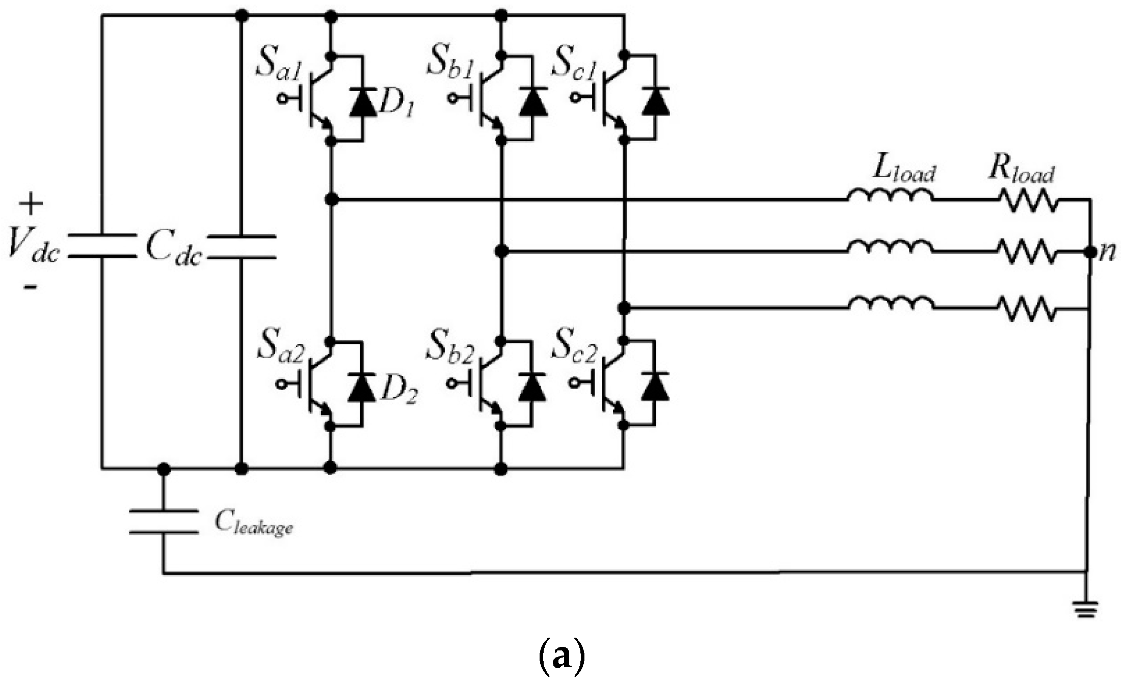
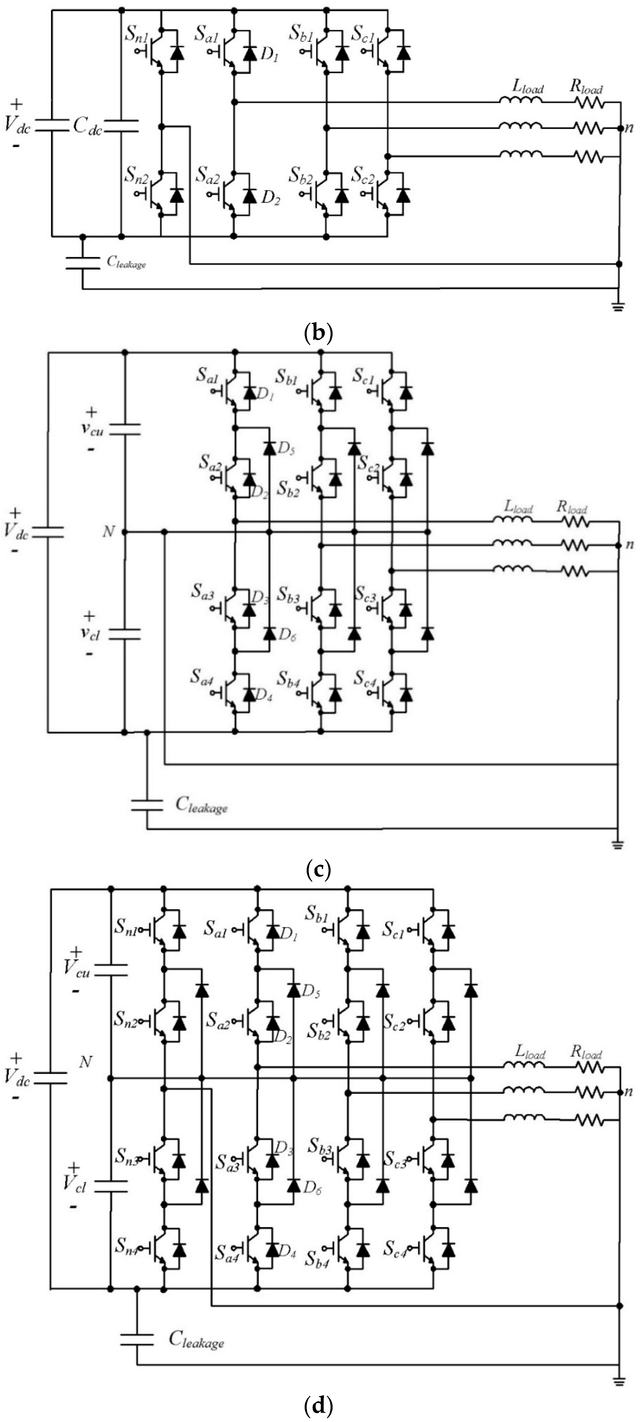
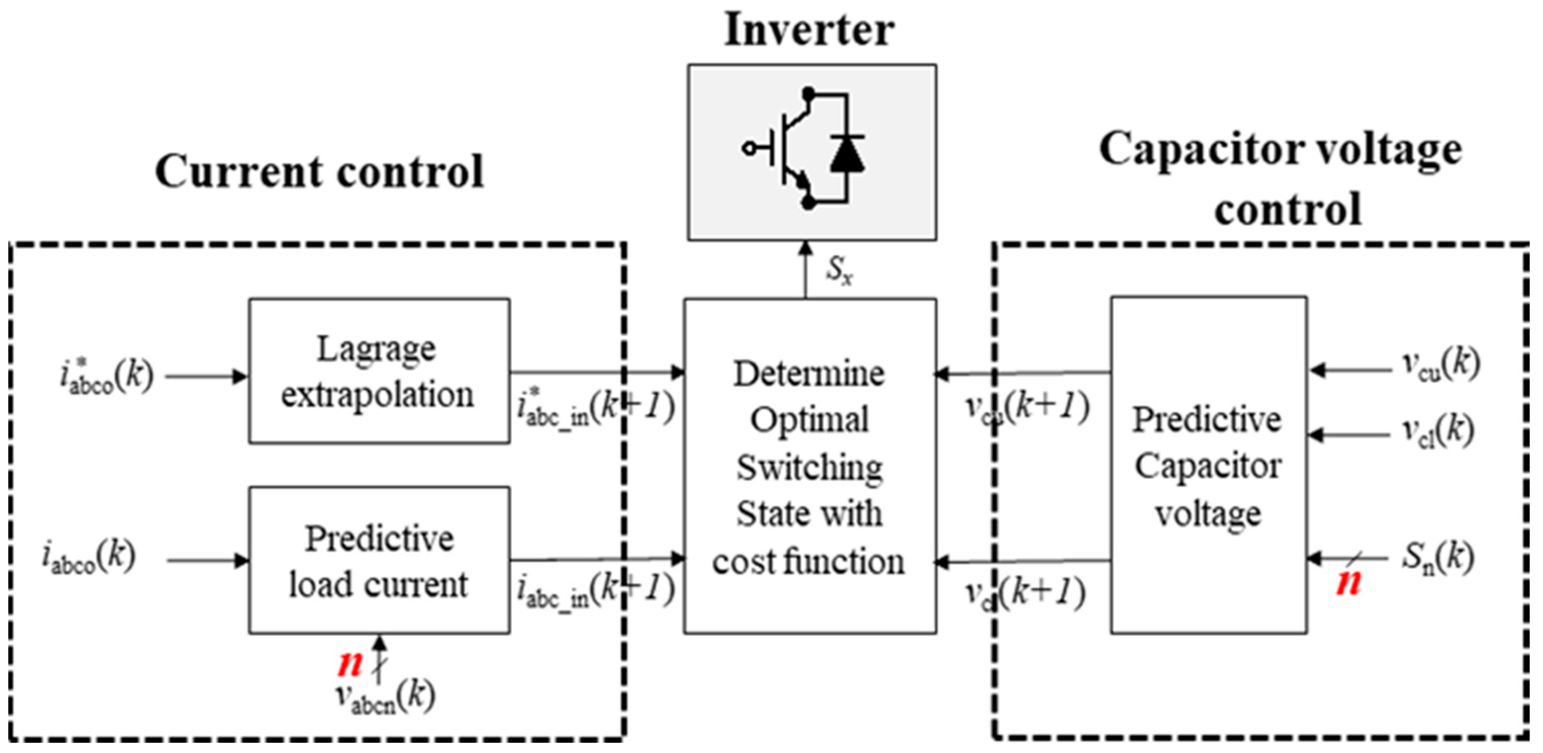
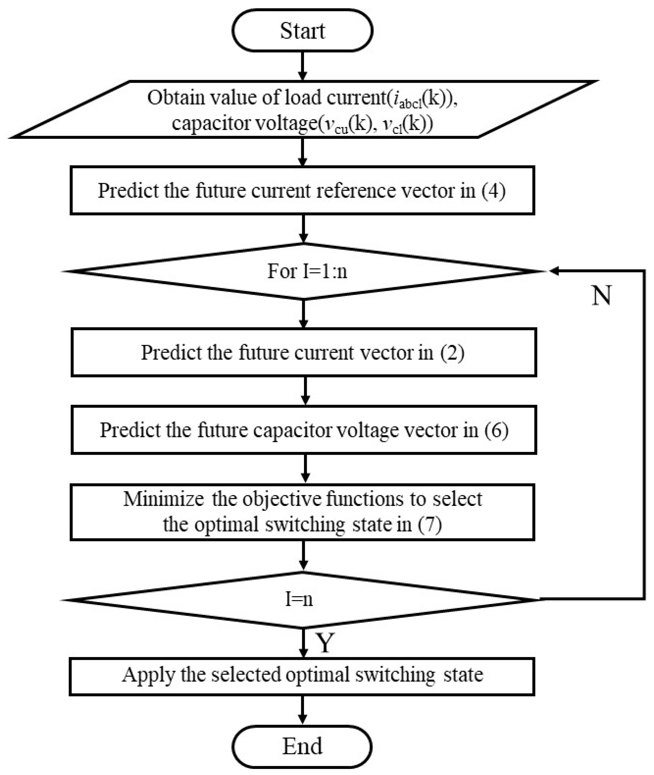
2. Finite-Control Set Model Predictive Control for Three-Phase Four-Wire Inverters

In order to apply the three-phase four-wire inverter to the power conversion system for wave energy converter, various three-phase four-wire inverters were compared. In addition, the three-phase four-wire inverters compared the performance of each inverter from the two-level inverter to the three-level inverter used as a power conversion system for conventional wave energy converter. Through this, the performance of a four-leg inverter suitable as an inverter for a power converter for wave power generation is confirmed.
As shown in Figure 1 below, the four-leg inverters have a two-level/three-leg topology (Figure 1a) two-level/four-leg topology (Figure 1b). A three-level/three-leg topology inverter (Figure 1c) and a three-level/four-leg inverter (Figure 1d) were compared, respectively.
The performance of each inverter was analyzed by applying the finite control set model predictive control (FCS-MPC). In order to apply model predictive control to each inverter shown in Figure 1, it is necessary to consider the control variable and switching state according to each inverter. Model predictive control is divided into current control and capacitor voltage control according to the output voltage level of the inverter. In the case of a two-level inverter, only the input current needs to be considered in the cost function, but in the three-level inverter, the input current and the capacitor voltage must be simultaneously considered in the cost function, and accordingly, the number of switching to be considered increases. Figure 2 shows the model predictive control block diagram of the inverter.
The current control part to apply the model predictive control to the inverter can be expressed as follows by using the R-L ( R L , L L ) load and the output current ( i a o , i b o , i c o ) for the output AC voltage of the inverter:
[ v a n v b n v c n ] = R L o a d [ i a o i b o i c o ] + L L o a d d d t [ i a o i b o i c o ]
Based on this, Equation (1) can be expressed as follows when predicting the next step current based on the discrete model:
[ i a o ( k + 1 ) i b o ( k + 1 ) i c o ( k + 1 ) ] = [ i a o ( k ) i b o ( k ) i c o ( k ) ] + L l o a d 1 T s p [ v a n ( k ) R L o a d i a o ( k ) v b n ( k ) R L o a d i b o ( k ) v c n ( k ) R L o a d i c o ( k ) ]
Based on Equation (2), the optimal switching state predicts the load current of the next step using all the switching states that the inverter can make. In addition, an optimal state can be selected by comparing this with the reference current. The optimal switching state is one that minimizes the cost function. The cost function of the current control part of the model predictive control is constructed as follows:
G c u r r e n t = | i a b c o * ( k + 1 ) i a b c o ( k + 1 ) |
The (k + 1)th reference current value for current control shown in Equation (3) can be obtained using the fourth-order Lagrange extrapolation formula as follows [23]:
[ i a o * ( k + 1 ) i b o * ( k + 1 ) i c o * ( k + 1 ) ] = 4 [ i a o * ( k ) i b o * ( k ) i c o * ( k ) ] 6 [ i a o * ( k 1 ) i b o * ( k 1 ) i c o * ( k 1 ) ] + 4 [ i a o * ( k 2 ) i b o * ( k 2 ) i c o * ( k 2 ) ] [ i a o * ( k 3 ) i b o * ( k 3 ) i c o * ( k 3 ) ]
Unlike two-level inverters, three-level inverters require capacitor voltage balancing control along with current control. Current control is the same as described above, and for capacitor voltage balancing control, the capacitor voltage change rate can be calculated as follows by using the current flowing through the DC capacitor:
d d t [ v c u v c l ] = C d c 1 [ i c u i c l ]
where i c u , i c l represents the current flowing through the capacitor and C d c represents the capacitance of the capacitor. When this is expressed in a discrete model like current control, the (k + 1)th capacitor voltage can be calculated as follows:
[ v c u ( k + 1 ) v c l ( k + 1 ) ] = [ v c u ( k ) v c l ( k ) ] + C d c 1 T s p [ i c u ( k ) i c l ( k ) ]
The cost function of the three-level inverter can be constructed using the current shown in Equation (2) and the capacitor voltage shown in Equation (6). Unlike the cost function of the two-level converter composed of only current control, the cost function composed of current control and capacitor voltage control can be expressed as follows:
G t o t a l = | i a b c o * ( k + 1 ) i a b c o ( k + 1 ) | + λ c a p | v c u ( k + 1 ) v c l ( k + 1 ) |
A three-level inverter must use redundant switching states for capacitor voltage balancing. In other words, although the voltage vector has the same effect on the output current, only the capacitor voltage has a different effect, so for balancing the capacitor voltage, the redundant switching vector must be appropriately selected. In the redundant switching state, the switching state affecting the upper capacitor with respect to the neutral point is represented by the P-Type switching state, and the switching state affecting the lower capacitor is represented by the N-Type switching state. In conclusion, the switching selection for balancing the capacitor voltage is made according to the current flowing through the capacitor based on the current state of the capacitor voltage.
Because the number of switching of the three-level inverter increases due to capacitor voltage balancing, the number of switching states that must be considered to select an optimal switching state increase, which also increases the amount of calculation. Furthermore, in the three-level four-leg inverter, the number of switching is increased to 81 because the neutral point of the power supply is connected to the four-leg inverter. The cost function of the three-level four-leg inverter can also be expressed as Equation (7), but the amount of calculation increases rapidly because the number of switching to be considered increases.
Figure 3 shows the flowchart of the model predictive control applied in this study. As shown in Figure 3, model predictive control selects the optimal switching state that minimizes the cost function by using the switching combinations that can be made in each topology. The number of switching combinations that each topology can make can be expressed as n, and Table 1, Table 2, Table 3 and Table 4 shows the switching combinations that each topology can make.
Figure 4 shows the voltage vectors that each inverter should consider. It can be seen that the voltage vector increases as the voltage level increases. Table 1, Table 2, Table 3 and Table 4 summarize the voltage vectors considered by each inverter. According to the switching state of the topology, the two-level topology has ‘P’ and ‘N’ states, and the three-level topology has ‘P’, ‘O’, and ‘N’ states, as shown in Table 1–4. ‘P’ state means that the upper switch is on, ‘O’ state means that the middle two switches are turned on in three-level topology, and ‘N’ state means that the lower switch is turned on. As in the space vector voltage of each topology, the number of voltage vectors considered by the three-level inverter increases compared to the two-level inverter, and the number of three-level four-leg inverters increases even more.
As the number of voltage vectors to be considered increases, the level of the output voltage increases, and accordingly, the rate of change of the output voltage decreases. That is, an increase in the number of voltage vectors to be considered increases the computational amount of the model predictive control and increases the burden, but may increase in terms of output performance. Therefore, in the next chapter, the output performance according to each topology will be compared through a simulation and an experiment.

3. Simulation and Experimental Results

In this study, to check the performance of each inverter, a two-level converter used as a power conversion device for wave power was used for the input rectifier part, and simulation was performed under the rated condition of the wave power device (30 kW). In this study, the rectifier was operated by applying the model predictive control. The parameters used in the wave power rectifier are shown in Table 5 below.
To check the performance of each inverter, the output characteristics of each inverter were compared under the same wave power generation rated conditions as the input rectifier as shown in Figure 5 and Figure 6. Model predictive control was applied to each inverter. For the output load of the inverter, 7.5 Ω and 24.2 mH were used as R-L loads, and the load power factor was 0.72. The performance of each inverter was analyzed under balanced load conditions and unbalanced load conditions. The unbalanced load condition created an unbalanced load condition by doubling the C-phase load resistance (Ra = Rb = 7.5 Ω, Rc = 15 Ω).
Figure 5 shows the output performance of four-leg inverters under balanced load conditions. First of all, it can be seen that the three-level inverter has a better output current performance than the two-level inverter under balanced load conditions. This can increase the performance of the output current as the three-level inverter increases the output voltage level. It can be seen from Figure 5 that the level of the line voltage increased by three levels rather than two levels. Additionally, it can be seen that the three-level inverter is excellent in leakage current performance. Among them, it can be seen that the three-level four-leg inverter has the best leakage current performance. It can be confirmed that the four-leg inverter also reduces leakage current through separate leg control. In conclusion, it can be seen that the output current performance of the three-level four-leg inverter is the best, and the leakage current performance is also the best.
Furthermore, the performance of four-leg inverters under unbalanced load conditions was compared. Figure 6 shows the output performance of each inverter under unbalanced load conditions. A two-level three-leg four-wire inverter or a three-level three-leg four-wire inverter does not directly control the individual legs, so the output current or leakage current performance is not good. However, in the case of a two-level four-leg inverter or three-level four-leg inverter that can control individual legs, it can be seen that the output current is properly controlled even when an unbalanced load occurs. Furthermore, in the case of the three-level four-leg inverter, it can be seen that the output current or leakage current performance is superior to that of the two-level four-leg inverter according to the increase of the output level.
Figure 7 shows a prototype picture of a three-level four-leg inverter. A hardware test was performed by applying model predictive control to a three-level four-leg inverter with the best output performance and leakage current performance among four-leg inverters. The dc power was supplied through the dc power supply in Figure 7, and the dc power consisted of a three-level three-leg inverter and a three-level four-leg inverter using individual phases. Each switch element is driven through a gate driver, and R-L Load is used for balanced and unbalanced load conditions. Model predictive control was implemented using DSP TI 28335 on the control board. Table 6 summarizes the conditions of the experiment.
Figure 8 shows the output performance of a three-level four-leg inverter under balanced and unbalanced loads. In the case of a three-level four-leg inverter, in order to apply the model predictive control, it is necessary to verify the hardware test because many switching states must be considered. As shown in Figure 8, it can be seen that the three-level four-leg inverter operates correctly under the unbalanced load condition as well as the balanced load condition. It can be seen that the three-level four-leg inverter operates with three-phase balanced current under balanced load conditions, and it can be seen that the neutral current is maintained at zero. Additionally, since it is a three-level inverter, it shows five-level line-to-line voltage. Additionally, it can be seen that the upper and lower capacitor voltages are balanced. It can be seen that the three-level four-leg inverter accurately controls the three-phase current even under unbalanced load conditions and flows in the neutral current as much as the unbalanced current. It can be seen that the line voltage for controlling the unbalanced load is also controlled. Figure 9 shows the simulation results under the same conditions as the experiment for verification of the experimental conditions, and results similar to the experimental results can be confirmed.
Figure 9 and Figure 10 compare and analyze the output performance of four-leg inverters under unbalanced load conditions. The unbalance index can be defined according to the output power of each phase load according to the reference current unbalance as follows:
Asy _ Index = ( P m a x P m i n ) / P m a x
where P m a x ,   P m i n represents the largest and smallest output power among the output powers of each phase according to the reference current imbalance, respectively. As the imbalance index increases, the difference between the maximum power and the minimum power increases. Figure 10, Figure 11, Figure 12 and Figure 13 compare the performance of each inverter by changing the output power and the unbalance index. Figure 10 and Figure 11 show that the inverter degrades as the unbalance index increases and the output power decreases. Two-level inverters significantly degrade the performance of the inverter as the unbalance index increases and the output power decreases. In addition, the three-stage four-section inverter shows the best performance in terms of output current (THD) or leakage current compared to other inverters regardless of the unbalance index. The DC voltage variability shown in Figure 12 increased the most as the load imbalance index and output power of the two-level three-leg inverter increased. However, the voltage fluctuation rates of the remaining inverters according to the load imbalance index and output power were almost similar. Additionally, as shown in Figure 13, in terms of total loss, two-level three-leg performance was the worst, and three-level performance was the best. In conclusion, it can be confirmed that the three-level four-leg topology can supply power most stably even if an unbalanced load occurs during independent operation of the wave power converter.
Using these various performance indicators, the excellent performance of the three-level four-leg topology was confirmed when comparing various four-leg inverter structures as well as the existing power converters for wave energy converters. In addition, applying the model predictive control to the three-level four-leg converter has the advantage that it can overcome fluctuations in wave energy and can be simply applied to the four-leg converter with a complex inverter topology. Table 7 summarizes variables not defined in the text.

4. Conclusions

Among the control methods of the existing wave energy converter, the control method for the power conversion system was insufficient. In particular, the model predictive control for fast response considering the wave energy characteristics was limited to the general two-level three-leg converter. Therefore, it is necessary to study the model predictive control that can reflect the characteristics of wave energy. In addition, it is necessary to study the increase in the capacity of the power conversion system according to the increase in the single capacity of the wave generator. In addition, it is necessary to study the topology of four-leg inverters that can respond to unbalanced load conditions during independent operation. Therefore, in this paper, the performance of various four-prong inverters, from two-stage inverters to three-stage inverters used as power converters for wave power converters, is compared. The four-leg converter was analyzed under each balanced load condition and unbalanced load condition by applying model predictive control. Comparisons for each topology were performed for current THD, leakage current, capacitor voltage fluctuation rate, and total loss. In conclusion, in terms of rated reference current THD performance, the three-level four-leg converter showed much better results than the two-level three-leg converter. It showed better results by about 70% under balanced load and 80% or more at unbalanced load. Based on this, it was confirmed that the three-level four-leg topology was suitable as a power converter for wave power converters.

Funding

This research received no external funding.

Conflicts of Interest

The authors declare no conflict of interest.

References

  1. Kouro, S.; Malinowski, M.; Gopakumar, K.; Pou, J.; Franquelo, L.G.; Wu, B.; Rodriguez, J.; Perez, M.A.; Leon, J.I. Recent Advances and Industrial Applications of Multilevel Converters. IEEE Trans. Ind. Electron. 2010, 57, 2553–2580. [Google Scholar] [CrossRef]
  2. Dijkhuizen, F. Multilevel converters: Review, form, function and motivation. In Proceedings of the EVER 2012, Monte-Carlo, Monaco, 10–13 October 2012. [Google Scholar]
  3. Chaturvedi, P.; Jain, S.; Agarwal, P. Carrier-Based Common Mode Voltage Control Techniques in Three-Level Diode-Clamped Inverter. Adv. Power Electron. 2012, 2012, 327157. [Google Scholar] [CrossRef]
  4. Videt, A.; Le Moigne, P.; Idir, N.; Baudesson, P.; Cimetiere, X. A New Carrier-Based PWM Providing Common-Mode-Current Reduction and DC-Bus Balancing for Three-Level Inverters. IEEE Trans. Ind. Electron. 2007, 54, 3001–3011. [Google Scholar] [CrossRef]
  5. Djeghloud, H.; Benalla, H. Space vector pulse width modulation applied to the three-level voltage inverter. IEEE Trans. Power Electron. 2004, 19, 732–738. [Google Scholar]
  6. Busquets-Monge, S.; Bordonau, J.; Boroyevich, D.; Somavilla, S. The nearest three virtual space vector PWM—A modulation for the comprehensive neutral-point balancing in the three-level NPC inverter. IEEE Power Electron. Lett. 2004, 2, 11–15. [Google Scholar] [CrossRef]
  7. Mohapatra, S.R.; Agarwal, V. Model Predictive Controller with Reduced Complexity for Grid-Tied Multilevel Inverters. IEEE Trans. Ind. Electron. 2018, 66, 8851–8855. [Google Scholar] [CrossRef]
  8. Yaramasu, V.; Rivera, M.; Wu, B.; Rodriguez, J. Model predictive current control of two-level four-leg inverters—Part I: Concept, algorithm, and simulation analysis. IEEE Trans. Power Electron. 2012, 28, 3459–3468. [Google Scholar] [CrossRef]
  9. Kim, S.-E.; Park, S.-Y.; Kwak, S. Simplified Model Predictive Control Method for Three-Phase Four-Leg Voltage Source Inverters. J. Power Electron. 2016, 16, 2231–2242. [Google Scholar] [CrossRef] [Green Version]
  10. Chan, R.; Kim, K.-H.; Park, J.-Y.; Kwak, S.-S. Simplified Model Predictive Control with preselection Technique for Reduction of Calculation Burden in 3-Level 4-Leg NPC Inverter. In Proceedings of the 2020 IEEE Applied Power Electronics Conference and Exposition (APEC), New Orleans, LA, USA, 15–19 March 2020; pp. 2291–2296. [Google Scholar] [CrossRef]
  11. Roh, C.; Kwak, S.; Choi, S. Three-phase three-level four-leg NPC converters with advanced model predictive control. J. Power Electron. 2021, 21, 1574–1584. [Google Scholar] [CrossRef]
  12. Mohapatra, S.R.; Agarwal, V. An Improved Reduced Complexity Model Predictive Current Controller for Grid-Connected Four-Leg Multilevel Inverter. IEEE Trans. Ind. Appl. 2019, 56, 498–506. [Google Scholar] [CrossRef]
  13. Falcão, A.F.; Cândido, J.J.; Justino, P.A.; Henriques, J.C. Hydrodynamics of the IPS buoy wave energy converter including the effect of non-uniform acceleration tube cross section. Renew. Energy 2012, 41, 105–114. [Google Scholar] [CrossRef]
  14. Babarit, A.; Clément, A. Optimal latching control of a wave energy device in regular and irregular waves. Appl. Ocean Res. 2006, 28, 77–91. [Google Scholar] [CrossRef]
  15. António, F.D.O. Modelling and control of oscillating-body wave energy converters with hydraulic power take-off and gas accumulator. Ocean. Eng. 2007, 34, 2021–2032. [Google Scholar]
  16. Cho, B.-H.; Yang, D.-S.; Park, S.-Y.; Choi, K.-S.; Lee, D.-H.; Byun, S.-H.; Jung, H. Modeling and control of a 75kW class variable liquid-column oscillator for highly efficient wave energy converter. Ocean Eng. 2011, 38, 436–443. [Google Scholar] [CrossRef]
  17. Luan, H.; Onar, O.C.; Khaligh, A. Dynamic Modeling and Optimum Load Control of a PM Linear Generator for Ocean Wave Energy Harvesting Application. In Proceedings of the 2009 Twenty-Fourth Annual IEEE Applied Power Electronics Conference and Exposition, Washington, DC, USA, 15–19 February 2009; pp. 739–743. [Google Scholar] [CrossRef]
  18. Wang, L.; Lee, D.-J.; Lee, W.-J.; Chen, Z. Analysis of a novel autonomous marine hybrid power generation/energy storage system with a high-voltage direct current link. J. Power Sources 2008, 185, 1284–1292. [Google Scholar] [CrossRef]
  19. Aubry, J.; Ben Ahmed, H.; Multon, B. Sizing Optimization Methodology of a Surface Permanent Magnet Machine-Converter System over a Torque-Speed Operating Profile: Application to a Wave Energy Converter. IEEE Trans. Ind. Electron. 2011, 59, 2116–2125. [Google Scholar] [CrossRef]
  20. Alberdi, M.; Amundarain, M.; Garrido, A.; Garrido, I. Neural control for voltage dips ride-through of oscillating water column-based wave energy converter equipped with doubly-fed induction generator. Renew. Energy 2012, 48, 16–26. [Google Scholar] [CrossRef]
  21. Park, J.S.; Hyon, B.J.; Yun, J.; Lee, J.; Choi, J.-Y.; Choi, J.-S.; Hong, K. Vector Control for Wave Power Generation System using Permanent Magnet Linear Synchronous Generator. J. Korean Soc. Mar. Environ. Energy 2016, 19, 120–128. [Google Scholar] [CrossRef]
  22. Blanco, M.; Ramirez, D.; Zarei, M.E.; Gupta, M. Dual multivector model predictive control for the power converters of a floating OWC WEC. Int. J. Electr. Power Energy Syst. 2021, 133, 107263. [Google Scholar] [CrossRef]
  23. Cortes, P.; Rodriguez, J.; Silva, C.; Flores, A. Delay Compensation in Model Predictive Current Control of a Three-Phase Inverter. IEEE Trans. Ind. Electron. 2011, 59, 1323–1325. [Google Scholar] [CrossRef]
Figure 1. Three-phase four-wire DC/AC inverter block diagram; (a) two-level/three-leg topology; (b) two-level/four-leg topology; (c) three-level/three-leg topology; (d) three-level/four-leg topology.
Energies 15 02839 g001aEnergies 15 02839 g001b
Figure 2. Block diagram of model predictive control for four-leg inverters.
Energies 15 02839 g002
Figure 3. Flowchart of model predictive control applied to this study.
Energies 15 02839 g003
Figure 4. Voltage vector diagram of four-leg inverter: (a) two-level three-leg four-wire type, (b) two-level four-leg type, (c) three-level three-leg four-wire type, and (d) three-level type four-leg inverter.
Energies 15 02839 g004aEnergies 15 02839 g004b
Figure 5. Comparison of output performance of a four-leg inverter (output current, output line voltage, DC voltage, leakage current) in balanced load conditions: (a) two-level three-leg four-wire type, (b) two-level four-leg type, (c) three-level three-leg four-wire type, and (d) three-level type four-leg inverter.
Energies 15 02839 g005aEnergies 15 02839 g005b
Figure 6. Comparison of output performance of a four-leg inverter (output current, output line voltage, DC voltage, leakage current) in unbalanced load conditions: (a) two-level three-leg four-wire type, (b) two-level four-leg type, (c) three-level three-leg four-wire type, and (d) three-level type four-leg inverter.
Energies 15 02839 g006aEnergies 15 02839 g006b
Figure 7. Prototype photo of a three-level three-phase four-leg inverter for application of the model predictive control technique.
Energies 15 02839 g007
Figure 8. Experiment output performance of a three-level four-leg inverter with model predictive control under (a) balanced and (b) unbalanced load conditions.
Energies 15 02839 g008
Figure 9. Simulation output performance of a three-level four-leg inverter with model predictive control under (a) balanced and (b) unbalanced load conditions with same input condition of experiment.
Energies 15 02839 g009
Figure 10. Comparison of current THD performance of a four-leg inverter under unbalanced load condition: (a) two-level three-leg four-wire type, (b) two-level four-leg type, (c) three-level three-leg four-wire type, and (d) three-level type four-leg inverter.
Energies 15 02839 g010
Figure 11. Comparison of leakage current performance of a four-leg inverter under unbalanced load condition: (a) two-level three-leg four-wire type, (b) two-level four-leg type, (c) three-level three-leg four-wire type, and (d) three-level type four-leg inverter.
Energies 15 02839 g011
Figure 12. Comparison of voltage volatility performance of a four-leg inverter under unbalanced load condition: (a) two-level three-leg four-wire type, (b) two-level four-leg type, (c) three-level three-leg four-wire type, and (d) three-level type four-leg inverter.
Energies 15 02839 g012
Figure 13. Comparison of total losses performance of a four-leg inverter under unbalanced load condition: (a) two-level three-leg four-wire type, (b) two-level four-leg type, (c) three-level three-leg four-wire type, and (d) three-level type four-leg inverter.
Energies 15 02839 g013
Table 1. Input voltage according to the switching state of the two-level three-leg inverter.
Voltage
Vectors
Switching
State
VoltageVoltage
Vectors
Switching
State
Voltage
vavbvcvavbvc
v1PPP111v5NPP011
v2NNN000v6PNN100
v3NNP001v7PNP101
v4NPN010v8PPN110
Table 2. Input voltage according to the switching state of the two-level four-leg inverter.
Voltage
Vectors
Switching
State
VoltageVoltage
Vectors
Switching
State
Voltage
vavbvcvavbvc
v1PPPP000v9PPPN111
v2NNNP−1−1−1v10NNNN000
v3PNNP0−1−1v11PNNN100
v4PPNP00−1v12PPNN110
v5NPNP−10−1v13NPNN010
v6NPPP−100v14NPPN011
v7NNPP−1−10v15NNPN001
v8PNPP0−10v16PNPN101
Table 3. Three-level three-leg input voltage state according to the switching state.
Voltage
Vectors
Switching
State
VoltageVoltage
Vectors
Switching
State
Voltage
vavbvcvavbvc
v1PPP0.50.50.5v15ONO0−0.50
v2NNN−0.5−0.5−0.5v16PON0.50−0.5
v3OOO000v17OPN00.5−0.5
v4POO0.500v18NPO−0.50.50
v5ONN0−0.5−0.5v19NOP−0.500.5
v6PPO0.50.50v20ONP0−0.50.5
v7OON00−0.5v21PNO0.5−0.50
v8OPO00.50v22PNN0.5−0.5−0.5
v9NON−0.50−0.5v23PPN0.50.5−0.5
v10OPP00.50.5v24NPN−0.50.5−0.5
v11NOO−0.500v25NPP−0.50.50.5
v12OOP000.5v26NNP−0.5−0.50.5
v13NNO−0.5−0.50v27PNP0.5−0.50.5
v14POP0.500.5
Table 4. Input voltage according to the switching state of the three-level four-leg inverter.
Voltage
Vectors
Switching
State
Output Phase VoltageVoltage
Vectors
Switching
State
Output Phase Voltage
vanvbnvcnvanvbnvcn
v1NNNN000v42OOOP−0.5−0.5−0.5
v2NNNO−0.5−0.5−0.5v43OOPN0.50.51
v3NNNP−1−1−1v44OOPO000.5
v4NNON000.5v45OOPP−0.5−0.50
v5NNOO−0.5−0.50v46OPNN0.510
v6NNOP−1−1−0.5v47OPNO00.5−0.5
v7NNPN001v48OPNP−0.50−1
v8NNPO−0.5−0.50.5v49OPON0.510.5
v9NNPP−1−10v50OPOO00.50
v10NONN00.50v51OPOP−0.50−0.5
v11NONO−0.50−0.5v52OPPN0.511
v12NONP−1−0.5−1v53OPPO00.50.5
v13NOON00.50.5v54OPPP−0.500
v14NOOO−0.500v55PNNN100
v15NOOP−1−0.5−0.5v56PNNO0.5−0.5−0.5
v16NOPN00.51v57PNNP0−1−1
v17NOPO−0.500.5v58PNON100.5
v18NOPP−1−0.50v59PNOO0.5−0.50
v19NPNN010v60PNOP0−1−0.5
v20NPNO−0.50.5−0.5v61PNPN101
v21NPNP−10−1v62PNPO0.5−0.50.5
v22NPON010.5v63PNPP0−10
v23NPOO−0.50.50v64PONN10.50
v24NPOP−10−0.5v65PONO0.50−0.5
v25NPPN011v66PONP0−0.5−1
v26NPPO−0.50.50.5v67POON10.50.5
v27NPPP−100v68POOO0.500
v28ONNN0.500v69POOP0−0.5−0.5
v29ONNO0−0.5−0.5v70POPN10.51
v30ONNP−0.5−1−1v71POPO0.500.5
v31ONON0.500.5v72POPP0−0.50
v32ONOO0−0.50v73PPNN110
v33ONOP−0.5−1−0.5v74PPNO0.50.5−0.5
v34ONPN0.501v75PPNP00−1
v35ONPO0−0.50.5v76PPON110.5
v36ONPP−0.5−10v77PPOO0.50.50
v37OONN0.50.50v78PPOP00−0.5
v38OONO00−0.5v79PPPN111
v39OONP−0.5−0.5−1v80PPPO0.50.50.5
v40OOON0.50.50.5v81PPPP000
v41OOOO000
Table 5. Parameter for inverter simulation.
ParametersValues
RLoad (Load resistance)7.5 Ω
LLoad (Load inductance)24.2 mH
Cdc (DC capacitance)4400 µF
Vdc (DC voltage)850 V
Tsp (sampling period)50 µs
Table 6. Parameter for the inverter experiment.
ParametersValues
RLoad (Load restistance)3 Ω
LLoad (Load inductance)18 mH
Cdc (DC capacitance)2200 µF
Vdc (DC voltage)50 V
Tsp (sampling period)200 µs
Table 7. Common abbreviations that do not need defining in the text.
AbbreviationMeaningUnits
V d c DC input voltageV
C d c DC capacitanceµF
v c u Upper capacitor voltageV
v c l Lower capacitor voltageV
R l o a d Load resistorΩ
L l o a d Load inductormH
v x n Load voltage (x = a, b, c)V
i x o Load current (x = a, b, c)A
i x o * Reference load current (x = a, b, c)A
G c u r r e n t Cost function of current controlA
i c u Upper capacitor currentA
i c l Lower capacitor currentA
G t o t a l Total cost functionA
λ c a p Weighting factorA/V
T H D i Total harmonic distortion%
i l e a k a g e Leakage currentA
Publisher’s Note: MDPI stays neutral with regard to jurisdictional claims in published maps and institutional affiliations.

