Article

Thermal Parameters Calibration and Energy-Saving Evaluation of Spectral Selective Absorption Film Coated Glazing System Based on Heat Transfer Simulation

1
School of Civil and Transportation Engineering, Hebei University of Technology, Tianjin 300401, China
2
School of Architecture, Tianjin University, Tianjin 300072, China
*
Author to whom correspondence should be addressed.
Energies 2022, 15(8), 2780; https://doi.org/10.3390/en15082780
Submission received: 3 March 2022 / Revised: 29 March 2022 / Accepted: 5 April 2022 / Published: 11 April 2022
(This article belongs to the Topic Building Energy and Environment)

Abstract

:
Spectral selective absorption film (SSAF), a solar control film, has a special energy-saving mechanism. In the previous studies of SSAF coated glazing systems, thermal parameters (global thermal transmittance (U) and solar heat gain coefficient (SHGC)) calculated by traditional algorithms were not verified. In order to evaluate the energy-saving effect of SSAF coated glazing systems accurately, U and the SHGC were calibrated and then used for energy consumption simulation. Firstly, the simulation models of the heat transfer process of SSAF coated glazing systems were established by COMSOL Multiphysics, considering simplified linear attenuation of radiative transfer. After being validated, the simulation models were used for the calibration of U and SHGC by the Multiple Linear Regression (MLR) model. As a result, the calibration coefficients of U and SHGC are 1.126 and 1.689, respectively. Secondly, the thermal parameters of SSAF coated glazing systems calibrated by the calibration coefficients were used for a building energy consumption simulation case. The result showed that the inner surface is the best coating position for single glazing systems (SG), while the outer surface is the best coating position for double glazing systems (DG) in hot summer and cold winter zone, hot summer and warm winter zone and the moderate zone of China.

1. Introduction

As one of the most vital industries in all walks of life in many countries, the construction industry has been consuming the major energy in operation, such as for heating, air-conditioning and refrigeration. In 2019, the energy consumption in building operation was 1.03 billion kW·h in China, according to “Research Report on Building Energy Consumption and Carbon Emission” in China (2021), accounting for 21.2% of the total national energy consumption [1]. A considerable part of the energy consumption in building operation is caused by the heat exchange between the building envelope and the outdoor environment. The external window (including glass curtain wall) is weak for energy saving and thermal insulation in building envelopes. Although the external windows of new buildings have realized satisfactory energy-saving progress because of the emergence and application of new transparent materials/structures such as multiglazing systems with Low-E coating, insulating glazing systems with PCM, insulating glazing systems with aerogels, etc., the single clear glazing system and double clear glazing system installed on the large amounts of existing buildings are not energy efficient. It demonstrates that the energy consumption caused by external windows of existing buildings accounted for about 40~50% of total energy consumption of buildings [2] and even as high as 65~80% in where priority is given to cooling loads [3].
However, the single clear glazing system and the double clear glazing system after installation would rarely be retrofitted due to high retrofitting costs, long construction time and influences on the use of existing buildings during construction. It has been reported that these problems can be solved by solar control films, a type of energy-saving materials directly coated on glazing whether in a liquid-applied [4,5] or solid-applied [6] manner. They not only can play the role of saving energy by regulating solar radiation and surface emissivity but also have the advantages of simple construction, low cost and environmentally friendly performances. Solar control films mainly include heat mirror film, low emissivity film, spectral selective absorption film (SSAF), etc. [7]. The energy-saving mechanism of SSAF is different from other films. Its main functional components include transparent conductive oxides including antimony tin oxide (ATO), indium tin oxide (ITO), tungsten bronzes (MxWO3, M including alkali metal elements Li, Na, K, Rb and CS) and its composites, which enable SSAFs to strongly absorb solar near-infrared radiation, blocking near-infrared radiation [8,9] off the room.
It is very necessary to clarify the energy-saving effect of SSAF, which is one of the most important issues for determining the prospects of its application. Currently, there is much research on it. Chamber tests with glazing systems were used to visually investigate the thermal insulation ability of SSAF. In a chamber test, Zhu et al. [10] confirmed that SSAF reduced the indoor temperature (Tin (K)) of the chamber by 14 °C. Full-scale case study could characterize the impact of SSAF on the indoor thermal environment. By conducting field research of typical buildings, Moretti et al. [11] confirmed that indoor temperatures decreased by 2–3 °C when SSAF reduced the incoming solar radiation by about 60% during sunny days in moderate climate. To better understand the thermal performance of SSAF from the mechanism, Alvarez et al. [12] and Xamán et al. [13,14] established the heat transfer models of an SSAF coated single glazing system (SG+F) and an SSAF coated double glazing system (DG+F). The temperature distribution, the boundary heating flux of SSAF coated glazing systems and Tin were numerically calculated by using FORTRAN computer language. In order to quantitatively evaluate the impact of SSAF on energy-saving, building performance softwares such as EnergyPlus, eQUEST and ESP-r were used to simulate energy consumption [15,16,17,18,19,20,21], which put forward the need to verify the model of energy consumption. Gijón-Rivera et al. [15], Li et al. [18], Moretti et al. [19], Teixeira et al. [16] and Pereira et al. [17,20] validated or calibrated entire models with experimental data.
As the decisive parameters determining the energy performance of glazing systems, global thermal transmittance (U) and solar heat gain coefficient (SHGC) usually together describe the applicability of a glazing system to different climatic conditions and its different energy-saving performance from other glazing systems [22]. However, the U and the SHGC of SSAF have not been verified. The U and the SHGC input into building performance simulation software were still calculated by traditional algorithms (as described in an ISO standard, ISO 9050: 2003 Glass in Building—Determination of Light Transmission, Solar Direct Transmission, Total Solar Energy Transmission, Ultraviolet Transmission and Related Glazing Factors and a Chinese industry standard, JGJ/T 151-2008 Calculation specification for thermal performance of windows, doors and glass-curtain walls). There was no proof to demonstrate exactly whether the values calculated by this method can also be applied to SSAF, both in the above standards and previous studies. It is clear that neither the results of traditional algorithms can apply to the U and the SHGC of an SSAF coated glazing system, nor the simulations of building energy consumption can work accurately. Although Cornaro [23] obtained the U and SHGC of an SSAF coated glazing system from a set of experiments with solar test boxes, the systematic error shall be eliminated later by a mass of experiments.
In this paper, the simulation model for the heat transfer process of SSAF-coated glazing systems will be established by numerical simulation software. After contrasting the results of heat transfer calculated by simulation results with that by U and SHGC, U and SHGC will be corrected by statistical analysis if necessary. The validated or calibrated U and SHGC will be helpful for effective building energy simulation and the accurate evaluation of energy-saving effect of SSAF-coated glazing systems.

2. Heat Transfer Simulation of SSAF-Coated Glazing Systems

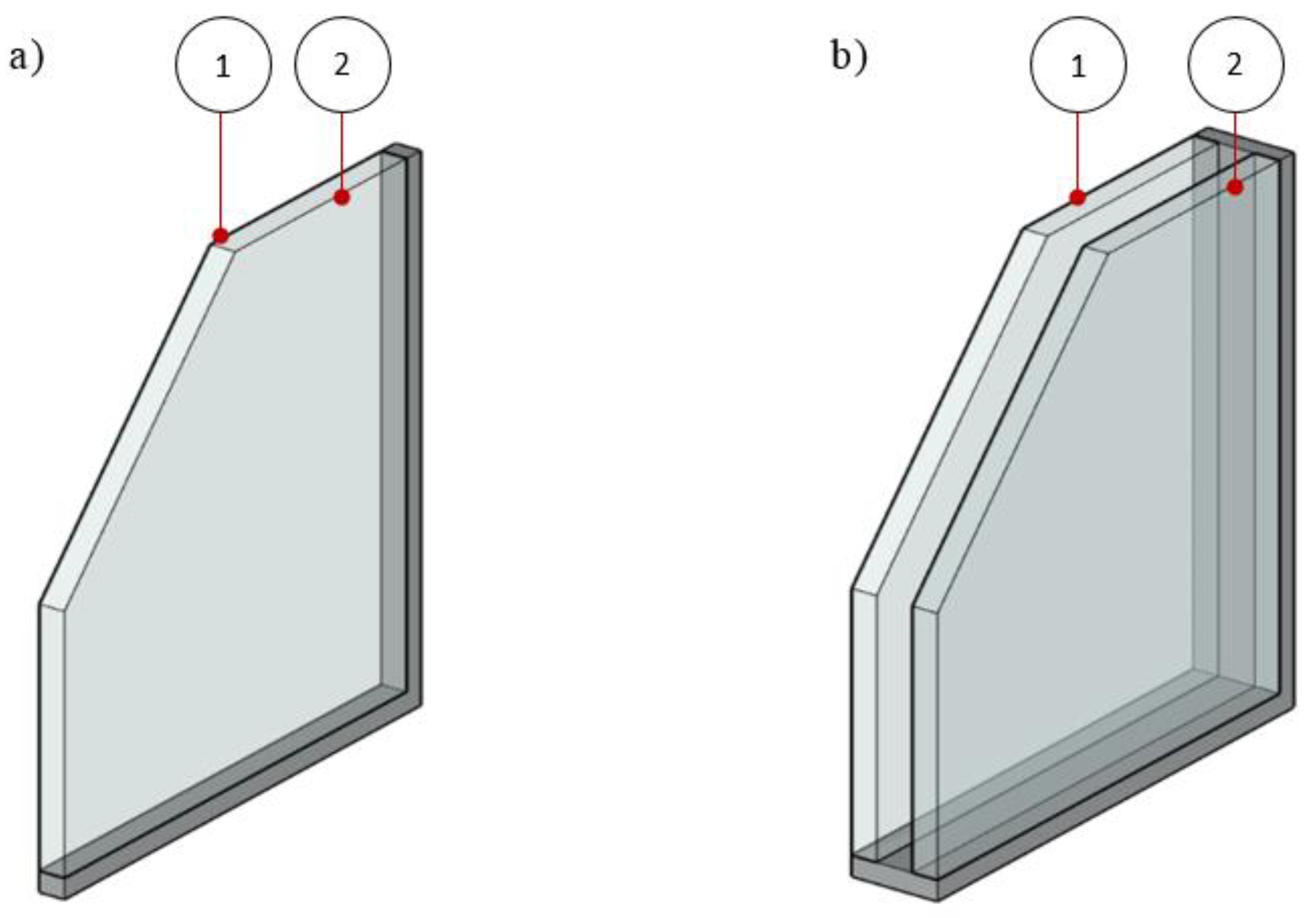
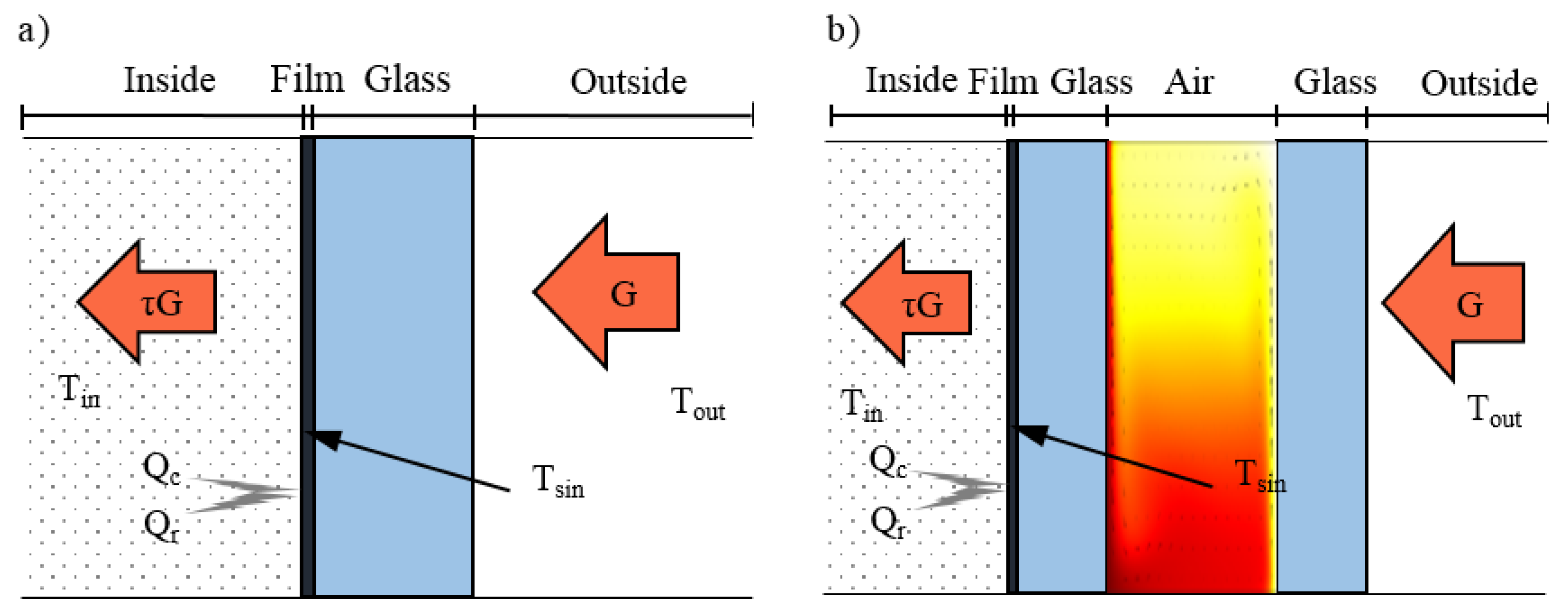
2.1. Description of Physical Model

As two typical forms of glazing systems in existing buildings, single glazing systems and double glazing systems can be coated with SSAF on the inner surface or the outer surface of them, as shown in Figure 1. Six millimeters of clear glass (SG) is a common form for single glazing systems; when coated with SSAF on the inner and the outer surface, it can be referred to as SG+F-in and SG+F-out, respectively, for the sake of simplicity; 6 mm clear glass + 12 mm air + 6 mm clear glass (DG) is a common form of double glazing systems, and when coated with SSAF on the inner surface and the outer surface, it can be referred to as DG+F-in and DG+F-out, respectively, for the sake of simplicity. These simplified expressions were used for the following studies.
The heat transfer processes of SG+F-in and DG+F-in (as the examples of SG+F and DG+F, respectively) in the daytime (with solar radiation) are shown in Figure 2. Solar energy (G (W/m3)) is assumed to strike perpendicularly to the glazing system from outdoor areas. For SG+F-in, some G directly enters the room through the coated glass (τ*G), some of G is absorbed by the SSAF and the glass and the rest is reflected, where τ is the transmissivity of the coated glazing system. The absorbed radiation energy is transformed into the internal energy of the coated glazing. Under the coupling effects of solar radiative absorption and the temperature difference between indoor and outdoor environments (outdoor temperature, Tout (K)), the heat exchange between the coated glazing system and the indoor environment is conducted by radiation (Qr) and convection (Qc). τ*G, Qc and Qr make up the total energy into a room through the glazing system. For DG+F, the difference between glazing temperatures on both sides of the cavity will cause a natural convection of internal fluid, and radiation will also be repeatedly reflected and transmitted on each surface.

2.2. Heat Transfer Simulation Modeling

Based on the heat transfer mechanism of SG+F and DG+F, two-dimensional heat transfer simulation models were established by numerical simulation software. With the continuous improvement of computer performance and numerical methods, many forms of numerical simulation software have been more widely used [24,25]. Compared with traditional numerical methods, numerical simulation software will provide more convenient tools for the in-depth study on the heat transfer process of SSAF-coated glazing systems, characterized by simpler and faster simulation process and more intuitive graphical simulation results. COMSOL Multiphysics is a numerical simulation software characterized by an open architecture that supports adding and modifying control equations in the graphical interface. Similarly to other heat transfer simulation software, COMSOL Multiphysics also has various built-in common physical models and can complete process operations such as process modeling, parameter and condition setting, calculation and post-processing through the built-in model tree. The coupling of transfer processes of the SSAF coated glass, including heat transfer, natural convection and radiation heat transfer, was achieved by the physical fields of solid heat transfers and surface-to-surface radiation in COMSOL Multiphysics.
In simulation models, the part of glazing was set as a body heat source. Although the radiative transfer in semi-transparent materials considering radiation absorption is considered to decay exponentially [26], it was simplified as linear decay, considering the high thermal conductivity and the thin thickness of the glazing. Then, the heat flow intensity of the body heat source (Qg(W/m2)) is as follows:
Qg = G0 × αg/Lg
where G0 is the total solar radiation intensity on the glass surface (W/m2); Lg is the glass thickness (m); and αg is the radiation absorptivity of the glass.
SSAF was set as a boundary heat source, and its heat flow intensity (QSSAF(W/m2)) is described as follows:
QSSAF = G0 × τg × αf
where τg is the solar radiation transmittance of glass; and αf is the radiation absorptivity of SSAF.
When the coating position changes, the simulation model can be established and solved by adaptively adjusting the boundary conditions mentioned above.

2.3. Validation of Simulation Model

In order to verify the effectiveness of simulation models, the optical and thermophysical properties of SSAF and the clear glass (as shown in Table 1) in the research of G must be examined. Data from Alvarez et al. [12] were used as the parameter conditions of the simulation model in this part.
Under the same boundary conditions (G = 750 W/m2, Tin = 21 °C, Tout = 0, 10, 20, 30, 40 and 50 °C, respectively), the transient-state temperature distribution of SG+F-in was simulated and solved in COMSOL Multiphysics. The difference between these simulation results and the numerical calculation results of G. Alvarez et al. is 0.49–0.86%, which might be caused by the difference of parameter accuracy and meshing. Considering that the above results of G. Alvarez et al. have been verified by experiments [27], it is obvious that the effectiveness of the heat transfer simulation model in COMSOL Multiphysics is acceptable.

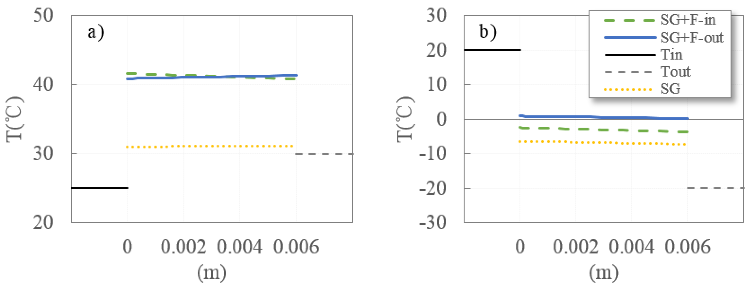
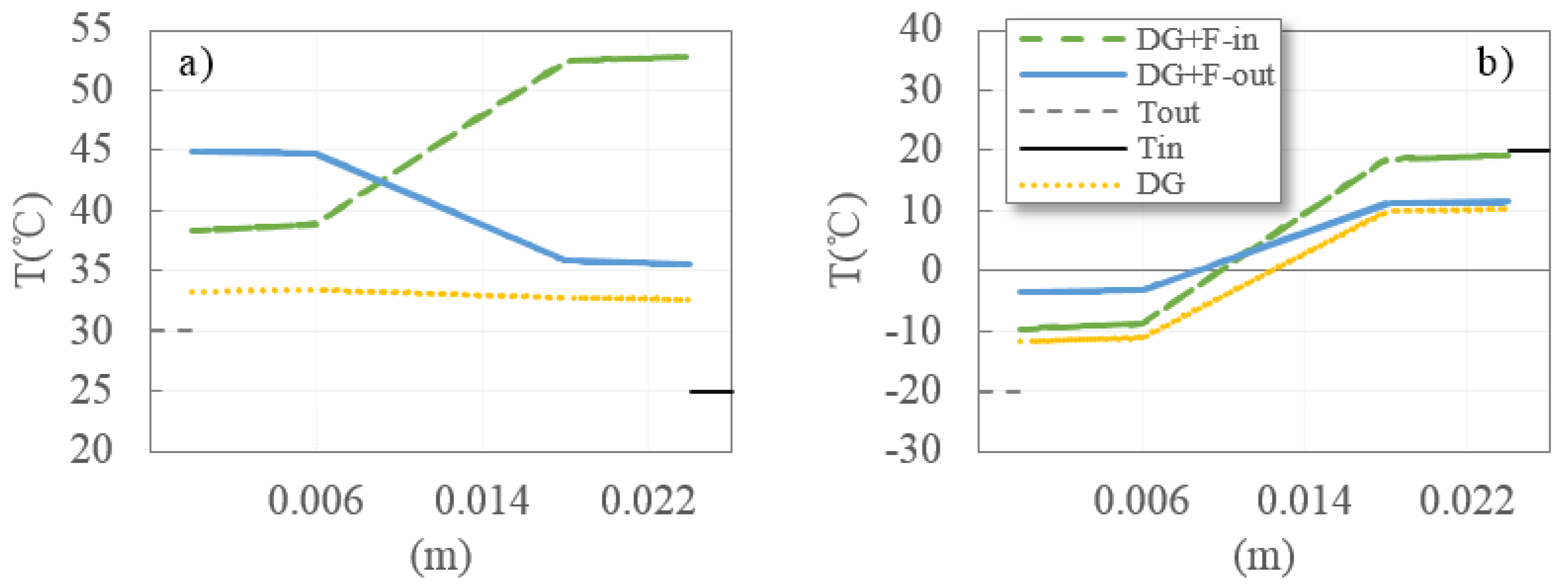
2.4. Heat Transfer Characteristics of SSAF Coated Glazing System in Typical Conditions

Depending on the cooling condition in summer or the heating condition in winter, the needed thermal performance of the SSAF coated glazing system is different. Therefore, the heat transfer simulations of SG+F and DG+F were conducted under typical conditions in summer (G = 500 W/m2, Tin = 25 °C, Tout = 30 °C) and winter (G = 300 W/m2, Tin = 20 °C, Tout = −20 °C), which were taken from JGJ/T 151-2008. The simulation results of SG+F and DG+F are shown in Figure 3 and Figure 4, respectively.
It can be seen from Figure 3 and Figure 4 that the heat transfer simulation results can clearly and quantitatively reflect the special heat transfer mechanism in which SSAF strongly absorbs solar radiation. The absorbed solar radiation is converted into internal energy of the SSAF-coated glazing system, bringing it higher temperature. The temperature increase in SG+F is the most obvious under the typical conditions in summer. For SG+F-in and SG+F-out, the inner surface temperature (Tsin), which directly affects the heat exchange between the coated glazing system and the indoor environment, is 41.59 °C and 40.92 °C, respectively. Tsin of SG+F-in and Tsin of SG+F-out are separately 8.31 °C and 7.65 °C higher than that of SG. This means that there will be more Qc, Qr and indoor heat gain. It seems that τ*G of SG or DG should be paid more attention, because they intuitively characterize the solar radiation directly entering the room. However, the changes of Qc and Qr should also be fully considered in view of the particularity of the heat transfer mechanism of the SSAF coated glazing. More accurate Qc and Qr will help to obtain more accurate indoor heat gains when using the SSAF-coated glazing system. Under the typical conditions in winter, Tsin of SG+F-in and Tsin of SG+F-out are higher than that of SG by 3.86 °C and 7.15 °C, respectively. It not only indicates that the changes of Qc and Qr caused by SSAF are different under different weather conditions but also highlights that different coating positions will bring significant differences in indoor heat gain through SSAF-coated glazing systems.
The difference of thermal performance caused by the coating positions is more obvious in DG+F. Under the typical conditions in summer and winter, although the Tin of DG+F is still higher than DG, the difference of Tin between DG+F-in and DG+F-out is 17.25 °C and 7.71 °C respectively, which means a more significant impact on indoor heat.

3. Applicability Verification of Classical Algorithm for Thermal Parameters of SSAF-Coated Glazing System

The applicability of the classical algorithm for the U and SHGC of SSAF-coated glazing systems is evaluated by comparing the theoretical heat transfer with the calculated heat transfer. The theoretical heat transfer was calculated by the temperature distribution of SSAF coated glass obtained by simulation, while the calculated heat transfer was obtained by U and SHGC of SSAF-coated glazing systems, which was calculated by the classical thermal parameters algorithm.

3.1. Calculation Method of Theoretical Heat Transfer

Based on Tsin of the coated glazing systems obtained by simulation, Qc can be obtained according to Newton’s law of cooling:
Q c = h i × ( T sin T in )
where hi is the convective heat transfer coefficient of the inner surface of the coated glazing system (W/(m2·K)).
Qr can be obtained according to Stefan–Boltzmann’s law:
Q r = σ × ε f × ( T sin 4 T in 4 )
where σ is Boltzmann constant, 5.67 × 10⁻⁸ W/(m2·K4), and εf is the surface emissivity of SSAF.
The theoretical total heat flux Q t into a room through the glazing system is as follows.
Q t = τ   ×   G + Q c   +   Q r

3.2. Calculation Method of Calculated Heat Transfer

According to the physical meaning of U and SHGC, the calculated total heat flux Q c a into a room through a glazing system is as follows.
Q ca   = G   ×   SHGC + U ×   ( T out   T in )  

3.3. Error Analysis of Calculated Heat Transfer

In order to minimize the influence of weather conditions used for heat transfer comparison, the temperature difference between indoor and outdoor was set to −40 °C (Tout = −20 °C, Tin = 20 °C), −10 °C (Tout= −10 °C, Tin = 20 °C), 5 °C (Tout = 30 °C, Tin = 20 °C) and 15 °C (Tout = −35 °C, Tin = 20 °C), and the solar radiation intensities were set to 200 W/m2, 500 W/m2 and 800 W/m2. The difference between Qca and Qt was calculated, and the results are shown in Figure 5.
It can be seen that there are obvious differences between Qca and Qt, which vary under different weather conditions. It is worth noting that this difference between SG+F and DG+F is not significant, but the difference gradually rises with the increase in solar radiation intensity. It shows that the U and the SHGC obtained directly by the classical algorithm do not fully consider the special heat transfer mechanism that SSAF strongly absorbs solar radiation. The U and the SHGC used by this method may further bring errors to building energy simulation and the energy-saving evaluation of SSAF. Therefore, it is necessary to calibrate the U and the SHGC of the coated glazing systems.

4. Calibration of Thermal Parameters of SSAF Coated Glazing Systems

4.1. Mechanism of Thermal Parameters Calibration

There are two kinds of calibration models for quantitative analysis parameters: multivariate linear calibration model and nonlinear calibration model. Multivariate linear correction models include Multiple Linear Regression (MLR), Principal Component Regression and Partial Least Squares Regression; nonlinear correction models include ANN, SVM, Kernel Partial Least Squares, etc. [28]. In this study, the MLR model was selected to calibrate the thermal parameters of SSAF-coated glazing systems, because it is simple to calculate and easy to understand.
Compared with U and SHGC calculated through traditional algorithms, the calibrated U and SHGC were set as U’ and SHGC’:
s . t . { U = α × U S H G C = β × S H G C
where α and β are calibration coefficients.
According to Equation (6), the total heat flux (Qca’ (W/m2)) into a room through the glazing system calculated by U’ and SHGC’ is as follows.
Q ca = ( T in T out ) × U + G × SHGC = ( T in T out ) × U × α + G × SHGC × β
According to Equations (7) and (8), the α and β can be expressed as follows.
[ α β ] = ( [ U × ( T in T out ) , G × SHGC ] T [ U × ( T in T out ) , G × SHGC ] ) 1 × [ U × ( T in T out ) , G × SHGC ] × Q ca

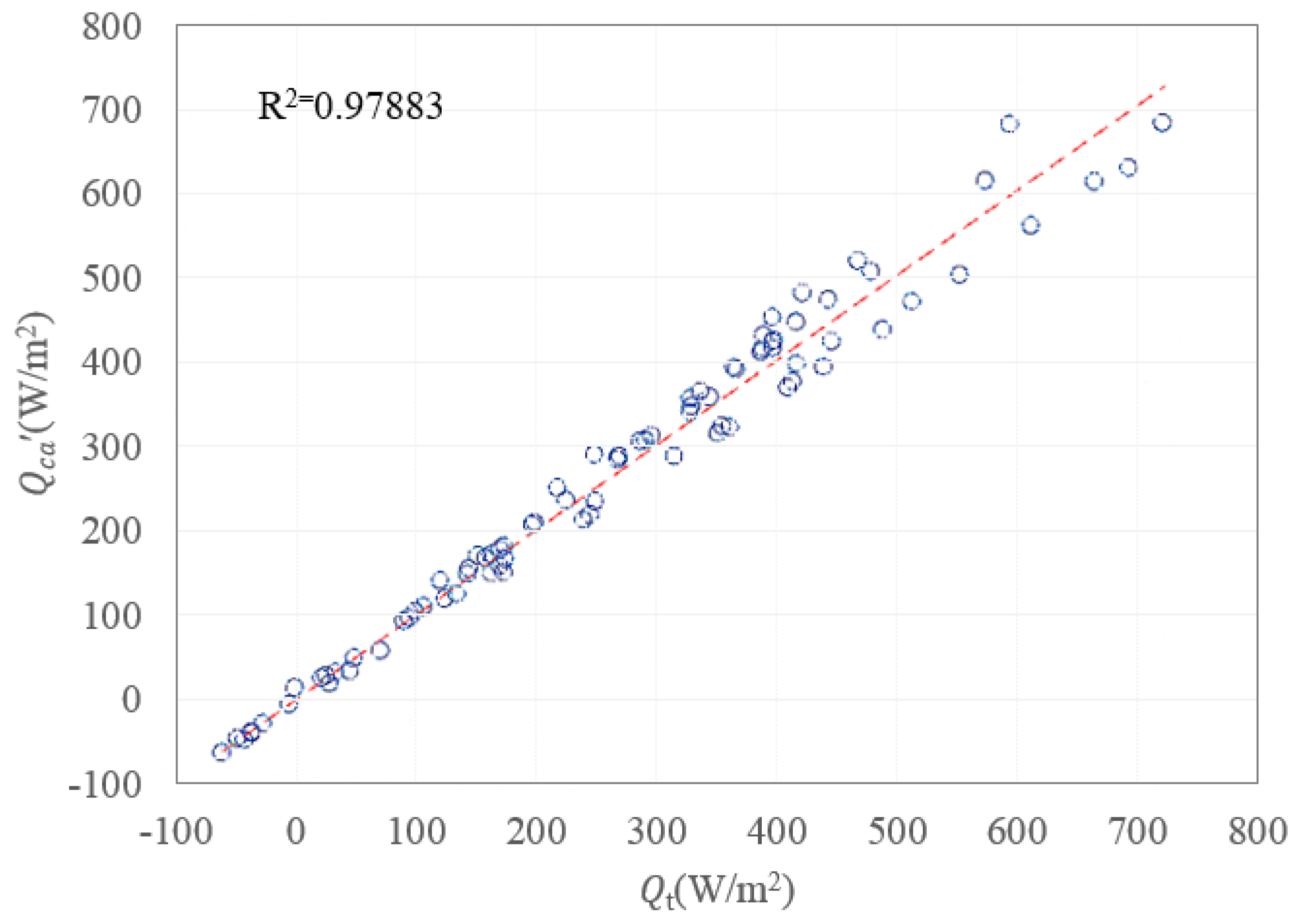
4.2. Solution and Verification of Calibration Coefficients

The calibration model of thermal parameters was established according to the mechanism of MLR and sampled by Latin Hypercube Sampling Method to generate 90 sample points. The parameters of these sample points included Tin and Tout (variable range [−20, 40] °C), solar radiation intensity (variable range [0, 1000] W/m2) and the types of the coated glazing systems (SG+F-in, SG+F-out, DG+F-in and DG+F-out). The Qt, the U and SHGC of these sample points were calculated and fed into MATLAB with the code of MLR. Consequently, α and β, the calibration coefficients as the results of thermal parameters calibration, are 1.126 and 1.689, respectively.
The determination coefficient (R2) of the calibration model was used to measure the fit degree between Q ca calculated by U’, SHGC’ and Q t . R2 is 0.97883, as shown in Figure 6, which indicates that the U and the SHGC calibrated by α and β have a good regressive relationship with theoretical heat transfer and embody the special heat transfer mechanism of SSAF completely.

5. Energy Performance of the SSAF Coated Glazing System

As shown in Table 2, there are the U’ and the SHGC’ of SG+F-in, SG+F-out DG+F-in and DG+F-out, which were calibrated by α and β and the U and the SHGC of SG and DG. These thermal parameters were input into building performance software to evaluate the energy-saving effect of SSAF by conducting a building energy consumption simulation of the coated and non-coated glazing system.
China has a vast territory and complex terrains, causing great differences in climate among regions. According to the difference of Tout, the country is divided into five climatic zones: severe cold zone, cold zone, hot summer and cold winter zone, moderate zone and hot summer and warm winter zone. In order to study the applicability of SSAF in different climate zones, energy consumption simulation was conducted in the representative cities of these five climatic zones: Harbin, Tianjin, Chongqing, Kunming and Guangzhou in severe cold zone, cold zone, hot summer and cold winter zone, moderate zone and hot summer and warm winter zone, respectively. The monthly temperatures and the global horizonal solar radiation intensity of these representative cities based on CSWD (Chinese Standard Weather Data) are shown in Figure 7, and vertical solar radiation closely related to the glazing was automatically calculated by the building performance software.

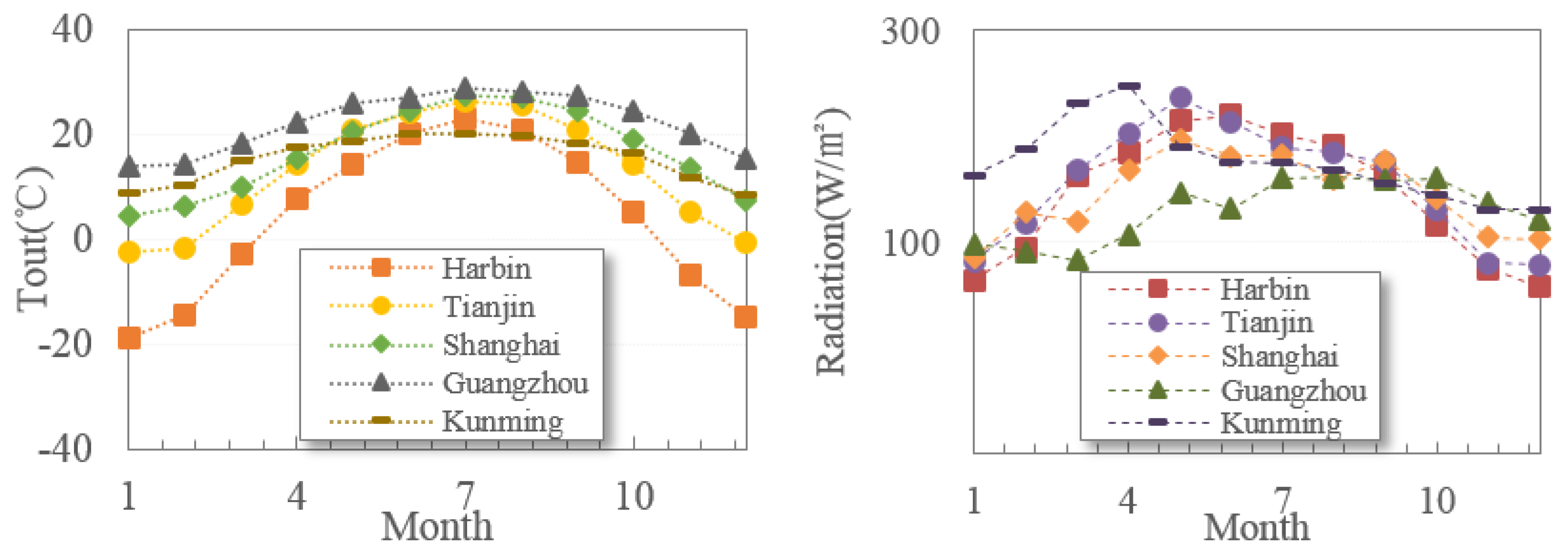
5.1. Building Model and Parameter Setting

The model of energy consumption simulation was established based on a typical existing office building. The model and its plan are shown in Figure 8. The total area of the office building is 1192 m2, mainly including offices, toilets, corridors, staircases and other functional spaces. Three-hundred and seventy millimeters of brick–concrete structure is used in the exterior wall system; 100 mm reinforced waterproof concrete slab is used in the roof system and 100 mm concrete slab is used in the floor system. The other corresponding thermal parameters were taken within the conventional value range of the corresponding structure. The annual energy consumption per unit area of buildings evaluated by EnergyPlus was taken as the scheme performance evaluation index in this study. In order to facilitate data comparison, the room air temperature in all energy demand assessments was set to 20 °C and 26 °C for heating and cooling, respectively, and the operating time of HVAC systems was set from 6 am to 6 pm. Other parameters were set by the general setting of the office building.

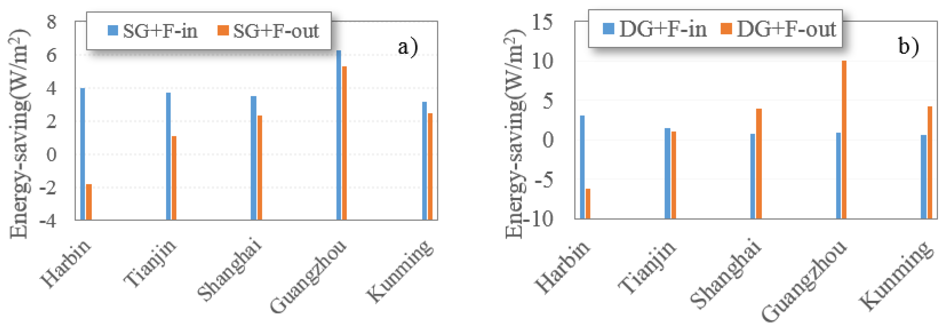
5.2. The Energy Performance of SSAF Coated Glazing System

It can be seen from Figure 9 that SSAF can reduce the building energy consumption of existing buildings with SG+F and DG+F in any climatic zones, but it is necessary to consider the optimum position of SSAF coating on the glazing system. In Harbin, compared with SG and DG, the building energy consumption of SG+F-out and DG+F-out increased by 1.80 W/m2 and 6.23 W/m2, which was the only case where SSAF did not save energy. For SG+F-in, the energy savings under the climatic conditions of Harbin, Tianjin, Shanghai, Guangzhou and Kunming were 3.96 W/m2, 3.68 W/m2, 3.51 W/m2, 6.28 W/m2 and 3.17 W/m2, respectively. Particularly in Tianjin, Shanghai, Guangzhou and Kunming, the energy savings were higher than SG+F-out by 2.60 W/m2, 1.18 W/m2, 0.99 W/m2 and 0.70 W/m2, respectively. Therefore, the inner surface is the best coating position to SG, when SSAF is applied in existing buildings of severe cold zone, cold zone, hot summer and cold winter zone, moderate zone and hot summer and warm winter zone. The energy-saving reached 3.68 W/m2~6.28 W/m2 in the situations above. The energy-saving potential of SSAF is the greatest in hot summer and warm winter zone.
The energy consumption of DG+F-in was lower than that of DG, but the limited energy saving was only 0.56 W/m2~3.10 W/m2. In Shanghai, Guangzhou and Kunming, when SSAF was coated on the outer surface of the glazing system, the energy saving of DG+F-out reached 3.89 W/m2, 10.00 W/m2 and 4.19 W/m2, respectively. It shows that when SSAF is applied to the double-glazing systems of the existing buildings in hot summer and cold winter zone, moderate zone and hot summer and warm winter zone, the outer surface is the best position. Among them, SSAF has the greatest energy-saving potential in hot summer and warm winter zones. However, in Harbin, a typical city in the severe cold zone, the energy-saving performance of SSAF was obtained only when applied on the inner surface. It should be noted in particular that although in Tianjin, a typical city in cold zone, coating SSAF on whether inner or outer surfaces could save energy, energy saving was only 1.54 and 1.01 W/m2. Therefore, whether SSAF is recommended or not, the economic benefits need to be considered, such as the investment payback period in this climate zone.
After the U and SHGC of the coated glazing systems are calibrated, the evaluation of energy performance of the coated glazing systems becomes easier and can better reflect the special mechanism of SSAF. Even without comparative experiments, it becomes convenient for SSAF-relevant energy performance comparison with other transparent materials/structures.

6. Conclusions

The heat transfer simulation models of SG+F and DG+F were established in COMSOL Multiphysics, where the radiative transfer in SSAF coated glazing systems was simplified as linear decay, the glass was set as a body heat source, and SSAF was set as a boundary heat source. Compared with previous numerical calculation results, the heat transfer simulation model proved acceptable. As the result of heat transfer simulation, temperature distributions of SG+F and DG+F clearly and quantitatively reflect the special heat transfer mechanism that SSAF strongly absorbs solar radiation and converts it into internal energy of the SSAF-coated glazing system. The heat transfer simulation models were used for the calibration of thermal parameters, including U and SHGC, by the MLR model. α and β, the calibration coefficients of U and SHGC, are 1.126 and 1.689, respectively, which have a good fit degree with theoretical heat transfer. Then, the thermal parameters of SSAF coated glazing system calibrated by α and β were used for a building energy consumption simulation case. The result showed that the inner surface is the best coating position of SSAF for the single glazing system (SG), while the outer surface is the best coating position for the double glazing system (DG) in hot summer and cold winter zone, hot summer and warm winter zone and moderate zone of China.

Author Contributions

X.C.: Methodology, software, validation and formal analysis; writing—original draft and visualization; S.Z.: conceptualization and resources; writing—review and editing, supervision and project administration; T.C.: formal analysis and data curation; writing—review and editing and visualization. All authors have read and agreed to the published version of the manuscript.

Funding

This research received no external funding.

Data Availability Statement

Not applicable.

Conflicts of Interest

The authors declare no conflict of interest.

References

  1. Research Report on Building Energy Consumption and Carbon Emission in China. 2021. Available online: https://mp.weixin.qq.com/s/tnzXNdft6Tk2Ca3QYtJT1Q (accessed on 28 December 2021).
  2. Gustavsen, A.; Grynning, S.; Arasteh, D.; Jelle, B.P.; Goudey, H. Key elements of and material performance targets for highly insulating window frames. Energy Build. 2011, 43, 2583–2594. [Google Scholar] [CrossRef]
  3. Huang, Y.; Niu, J.; Chung, T. Study on performance of energy-efficient retrofitting measures on commercial building external walls in cooling-dominant cities. Appl. Energy 2013, 103, 97–108. [Google Scholar] [CrossRef]
  4. Curcija, C.; Goudey, H.; Mitchell, R.; Manes, L.; Selkowitz, S. Liquid-Applied Absorbing Solar Control Window Film Retrofit; Lawrence Berkeley National Laboratory—Windows and Envelope Materials Group: San Francisco, CA, USA, 2014. [Google Scholar]
  5. Berardi, U. Light transmittance characterization and energy-saving analysis of a new selective coating for in situ window retrofit. Sci. Technol. Built Environ. 2019, 25, 1152–1163. [Google Scholar] [CrossRef]
  6. Calama-González, C.M.; León-Rodríguez, Á.L.; Suárez, R. Daylighting Performance of Solar Control Films for Hospital Buildings in a Mediterranean Climate. Energies 2019, 12, 489. [Google Scholar] [CrossRef] [Green Version]
  7. Khaled, K.; Berardi, U. Current and future coating technologies for architectural glazing applications. Energy Build. 2021, 244, 111022. [Google Scholar] [CrossRef]
  8. Yin, X.; Zhang, Z.; Wu, M.; Zhang, J.; Xu, G. Toward transparent composite films with selective solar spectral, flame retardant and thermal insulation functions. Mater. Chem. Phys. 2018, 216, 365–371. [Google Scholar] [CrossRef]
  9. Dalapati, G.K.; Kushwaha, A.K.; Sharma, M.; Suresh, V.; Shannigrahi, S.; Zhuk, S.; Masudy-Panah, S. Transparent heat regulating (THR) materials and coatings for energy saving window applications: Impact of materials design, micro-structural, and interface quality on the THR performance. Prog. Mater. Sci. 2018, 95, 42–131. [Google Scholar] [CrossRef]
  10. Zhu, S.; Chen, X.; Chen, T. Evaluation of thermal and energy performance of spectral selective absorbing film using outdoor measurements in cold climate. Arab. J. Geosci. 2021, 14, 1672. [Google Scholar] [CrossRef]
  11. Moretti, E.; Belloni, E. Evaluation of energy, thermal, and daylighting performance of solar control films for a case study in moderate climate. Build. Environ. 2015, 94, 183–195. [Google Scholar] [CrossRef]
  12. Alvarez, G.; Estrada, C.A. Transient heat conduction in a glass with chemically deposited SnS–CuxS solar control coating. Renew. Energy 1995, 6, 1023–1027. [Google Scholar] [CrossRef]
  13. Xamán, J.; Jiménez-Xamán, C.; Álvarez, G.; Zavala-Guillén, I.; Hernández-Pérez, I.; Aguilar, J.O. Thermal performance of a double pane window with a solar control coating for warm climate of Mexico. Appl. Therm. Eng. 2016, 106, 257–265. [Google Scholar] [CrossRef]
  14. Xamán, J.; Olazo-Gómez, Y.; Zavala-Guillén, I.; Hernández-Pérez, I.; Aguilar, J.O.; Hinojosa, J.F. Thermal evaluation of a Room coupled with a Double Glazing Window with/without a solar control film for Mexico. Appl. Therm. Eng. 2017, 110, 805–820. [Google Scholar] [CrossRef]
  15. Gijón-Rivera, M.; Álvarez, G.; Beausoleil-Morrison, I.; Xamán, J. Appraisal of thermal performance of a glazed office with a solar control coating: Cases in Mexico and Canada. Build. Environ. 2011, 46, 1223–1233. [Google Scholar] [CrossRef]
  16. Teixeira, H.; Gomes, M.G.; Moret Rodrigues, A.; Pereira, J. Thermal and visual comfort, energy use and environmental performance of glazing systems with solar control films. Build. Environ. 2020, 168, 106474. [Google Scholar] [CrossRef]
  17. Pereira, J.; Glória Gomes, M.; Moret Rodrigues, A.; Almeida, M. Thermal, luminous and energy performance of solar control films in single-glazed windows: Use of energy performance criteria to support decision making. Energy Build. 2019, 198, 431–443. [Google Scholar] [CrossRef]
  18. Li, C.; Tan, J.; Chow, T.; Qiu, Z. Experimental and theoretical study on the effect of window films on building energy consumption. Energy Build. 2015, 102, 129–138. [Google Scholar] [CrossRef]
  19. Moretti, E.; Belloni, E.; Lascaro, E. The Influence of Solar Control Films on Energy and Daylighting Performance by Means of Experimental Data and Preliminary Unsteady Simulations. Energy Procedia 2015, 78, 340–345. [Google Scholar] [CrossRef] [Green Version]
  20. Pereira, J.; Rivero, C.C.; Gomes, M.G.; Rodrigues, A.M.; Marrero, M. Energy, environmental and economic analysis of windows’ retrofit with solar control films: A case study in Mediterranean climate. Energy 2021, 233, 121083. [Google Scholar] [CrossRef]
  21. Chen, X.; Zhu, S.; Chen, T. Performance of a Solar Spectrum-Selective Absorption Film as a Building Energy-Saving Retrofit in China. ACS Omega 2021, 6, 31457–31468. [Google Scholar] [CrossRef]
  22. Singh, M.C.; Garg, S.N. Energy rating of different glazings for Indian climates. Energy 2009, 34, 1986–1992. [Google Scholar] [CrossRef]
  23. Cornaro, C.; Bucci, F.; Pierro, M.; Bonadonna, M.E.; Siniscalco, G. A new method for the thermal characterization of transparent and semi-transparent materials using outdoor measurements and dynamic simulation. Energy Build. 2015, 104, 57–64. [Google Scholar] [CrossRef]
  24. Merlin, S.; Macmanus, C.; Yann, R. Modelling and numerical simulation of hygrothermal transfer through a building wall for locations subjected to outdoor conditions in Sub-Saharan Africa. J. Build. Eng. 2019, 26, 100901. [Google Scholar]
  25. Merlin, S.; Romain, R.; Razika, K.; Lyes, B.; Macmanus, N.; Yann, R. Modeling, numerical simulation and validation of the hygrothermal transfer through a wooden building wall in Nancy, France. Therm. Sci. Eng. Prog. 2022, 22, 100808. [Google Scholar]
  26. Modest, M.F. Radiative Heat Transfer; Elsevier: Amsterdam, The Netherlands, 2013. [Google Scholar]
  27. Alvarez, G.; Jiménez, D.N.; Estrada, C.A. Thermal performance of solar control coatings: A mathematical model and its experimental verification. J. Phys. D Appl. Phys. 1998, 31, 2249. [Google Scholar] [CrossRef]
  28. Tan, C.; Li, M.; Qin, X. Random Subspace Regression Ensemble for Near-Infrared Spectroscopic Calibration of Tobacco Samples. Anal. Sci. Int. J. Jpn. Soc. Anal. Chem. 2008, 24, 647. [Google Scholar] [CrossRef] [Green Version]
Figure 1. The positions of SSAF for existing buildings’ glazing systems: (a) single glazing system (① the inner surface and ② the outer surface); (b) double glazing system (① the inner surface and ② the outer surface).
Energies 15 02780 g001
Figure 2. Heat transfer process of SSAF coated glazing systems: (a) SG+F [21]; (b) DG+F (Tsin: the inner surface temperature).
Energies 15 02780 g002
Figure 3. Temperature distribution of SG+F under typical conditions: (a) in summer; (b) in winter.
Energies 15 02780 g003
Figure 4. Temperature distribution of DG+F under typical conditions: (a) in summer; (b) in winter.
Energies 15 02780 g004
Figure 5. The difference between Qca and Qt.
Energies 15 02780 g005
Figure 6. R2 of the calibration model.
Energies 15 02780 g006
Figure 7. The monthly temperature and solar radiation intensity of the representative cities.
Energies 15 02780 g007
Figure 8. The typical building model and its plan: (a) the model; (b) the plan.
Energies 15 02780 g008
Figure 9. The energy-saving potential of SSAF: (a) SG+F; (b) DG+F.
Energies 15 02780 g009
Table 1. Optical and thermophysical properties of the SSAF and the clear glass.
ParametersLg (mm)αgτgαf
Values60.140.780.64
Table 2. The thermal parameters of glazing systems.
The Type of Glazing SystemsU(W/(m2·K)SHGCU’ (W/(m2·K)SHGC’
SG5.700.81
DG2.800.75
SG+F-in 4.400.58
SG+F-out 5.260.60
DG+F-in 2.440.72
DG+F-out 2.650.47
Publisher’s Note: MDPI stays neutral with regard to jurisdictional claims in published maps and institutional affiliations.

