Article

Direct Participation of Dynamic Virtual Power Plants in Secondary Frequency Control

Ecole Centrale Nantes-LS2N, 44321 Nantes, France
*
Author to whom correspondence should be addressed.
Energies 2022, 15(8), 2775; https://doi.org/10.3390/en15082775
Submission received: 8 March 2022 / Revised: 28 March 2022 / Accepted: 6 April 2022 / Published: 10 April 2022

Abstract

:
This paper proposes a novel control strategy in which Renewable Energy Sources (RES) considered in a new Dynamic Virtual Power Plant (DVPP) concept directly participate to Secondary Frequency Control (SFC). This allows full participation of these generators to SFC, i.e., in the same manner as classic synchronous generators by fulfilling identical specifications from both control and contractual points of view. An internal real-time redispatch has been proposed to account in DVPP in order to determine the amount of active power injection by each RES unit for the provision of frequency support at the secondary level. The whole control scheme is designed to take into account both rapid and slow dynamics of modern power systems which contain both classic synchronous generators and rapid power electronics for renewable energy sources in which DVPP is supposed to be inserted. The performance of secondary frequency control strategy has been validated through simulation studies on a two-area benchmark with mixed wind power plants and classic synchronous generators. This work is part of the H2020 POSYTYF project

1. Introduction

The high penetration of Renewable Energy Sources (RES) in modern power grids is of critical importance for the transformation of the global energy system [1,2,3,4]. However, stability and participation to ancillary services issues related to RES is a significant challenge that should be taken into account. Improvements of classic Secondary Frequency Control (SFC) have been recently proposed for RES and electrical vehicles’ integration to such control [5,6] or to take into account the impact of inertia emulation of HVDC tie-lines [7].
Furthermore, the RES grid integration faces major limitations due to the high rate of RES penetration [8]. A solution to overcome this is to group several RES into a systemic object called Dynamic Virtual Power Plant (DVPP) [9]. DVPP is a way to aggregate RES sources to form a portfolio of dispatchable/non-dispatchable RES able to optimally internally redispatch resources in case of meteorological and system variations in order to provide sufficient flexibility, reliable power output and grid services.
Due to the massive integration of RES, it is essential that they contribute to the provision of ancillary services such as frequency support. In the case of wind and solar RES generators, a secondary reserve is ensured by considering a deloading primary control which provides an active power margin in the MPPT algorithm [10] (usually this margin is 10% of the nominal power of the generator).
In the previous publications which have been studied in the review papers of [11,12], RES indirectly participate in the provision of ancillary service. In such indirect participation, RES partially contribute to secondary frequency control through decreasing frequency deviation [13,14,15,16].
In this paper, the main goal is the integration of DVPP to the existing secondary control frame in order to provide secondary frequency support in the same manner as classic synchronous generators such as thermal, gas, and hydro. To do so, direct participation of DVPP to SFC is taken into account on equal basis (obligations, operation and remuneration) with classic synchronous generators. Previous approaches proposed different aggregator business models to insert RES grouped in different Virtual Power Plant concepts into energy markets [17,18,19,20]. Our DVPP concept integrates both dynamic and optimal/market levels [9]. These two tasks are implemented into a hierarchical scheme decoupled in time. Optimal energy management of the DVPP, both from an internal point of view and for participation to markets is performed by an optimization function which is solved with a slow periodicity (a few minutes) [9,21,22]. Notice that this optimization stage also provides the deloading margins for each RES generator of the DVPP. Dispatch issued by this function is applied by a dynamic control which complies with classic SFC control. A solution for the latter dynamic level is presented in this work. It is provided as a way to integrate this control action in compliance with all aforementioned levels of control, in a robust way and avoiding bad dynamic interactions. These are the main contributions of the presented work.
The proposed control approach lays on an innovatory modeling. Indeed, classic hypotheses for the separation of voltage and frequency dynamics used until now no longer hold for RES connected to the grid by power electronics as they have both rapid voltage and frequency dynamics. The model introduced in [23] is used here to combine these dynamics into a simple mathematical object used both for the control and simulation validations.
Moreover, in order to ensure the full participation of DVPP in the provision of secondary frequency support, an internal redispatch strategy has been considered inside the DVPP, which fulfils the constant amount of injected active power by DVPP in order to reduce the need for electrochemical energy storage.
This paper is structured as follows: Section 2 presents the problem formulation and framework of the approach. Section 3 presents the new control for the direct participation of DVPP to SFC. The simulation results are presented in Section 4 while Section 5 is devoted to conclusions.

2. Problem Formulation and Framework of the Approach
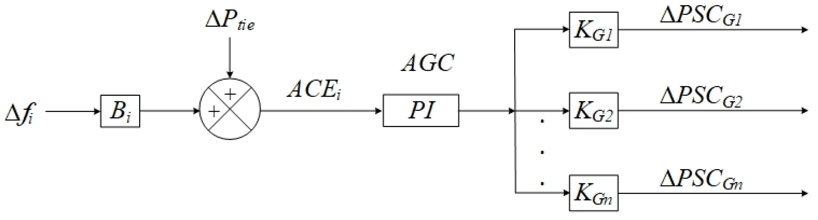
2.1. Classic SFC

The Secondary Frequency Control (SFC), also called Automatic Generation Control (AGC) or Load Frequency Control (LFC), is a high-level control with two main goals: the first one is to maintain frequency into a desirable range and the second one is to control the power exchange programmes between different control areas [24]. More specifically, the secondary regulation service for the frequency should provide the following specifications:
  • Frequency deviation of each SFC area i should go to zero: Δ f i t 0 ,
  • The deviation of each tie-lines power exchange between areas should go to zero: Δ P t i e t 0 .
These two objectives are usually gathered into a common control signal called Area Control Error (ACE) as in Figure 1, which shows the general SFC control block diagram. ACE is achieved from the combination of frequency deviation of the area ( Δ f i ) and the tie-line power between areas ( Δ P t i e ) (1). K G 1 , K G 2 , and, K G n , are the participation factors which determine the amount of active power with which each generator participates to SFC ( Δ P S C G n ).
A C E i = Δ P t i e + B i Δ f i

2.2. Indirect Participation of DVPP to Classic SFC

For all up to date SFC control implementations (see, e.g., reviews [11,12] which are the two most up to date review papers about the participation of renewable energy sources (especially wind power plants) in frequency control, renewable energy sources indirectly contribute to SFC. Figure 2 shows the block diagram for the indirect participation of DVPP to SFC as proposed in [13,14,15,16]. Indeed, DVPP only contributes to reduce the frequency deviation of the zone by its independent PI control, while the classic synchronous generators (thermal, hydro, and gas) directly contribute to SFC with participation factors ( K t , K h , K g ) to correct ACE.
The RES does not participate in the SFC in the regulatory sense (of contractual obligations and availability of the service). Furthermore, from the technical point of view, their contributions are not quantified. RES ensures some positive impact on frequency deviations when they can (availability of natural resources and unilateral decision to participate) and no contribution to the areas power exchange regulation.
To enhance the participation of the DVPP to frequency ancillary services, a method for direct participation to SFC is proposed in this paper to overcome the above-mentioned limitations and to allow DVPP to behave like a large classic generator.

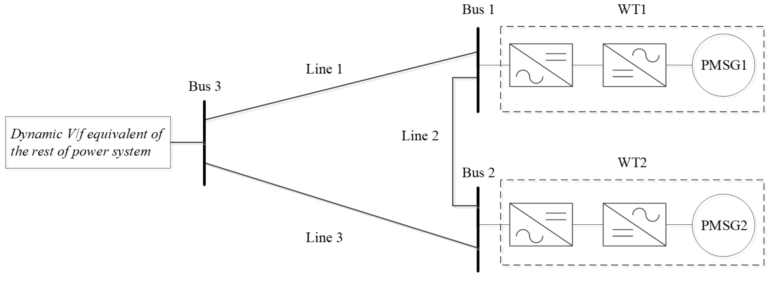
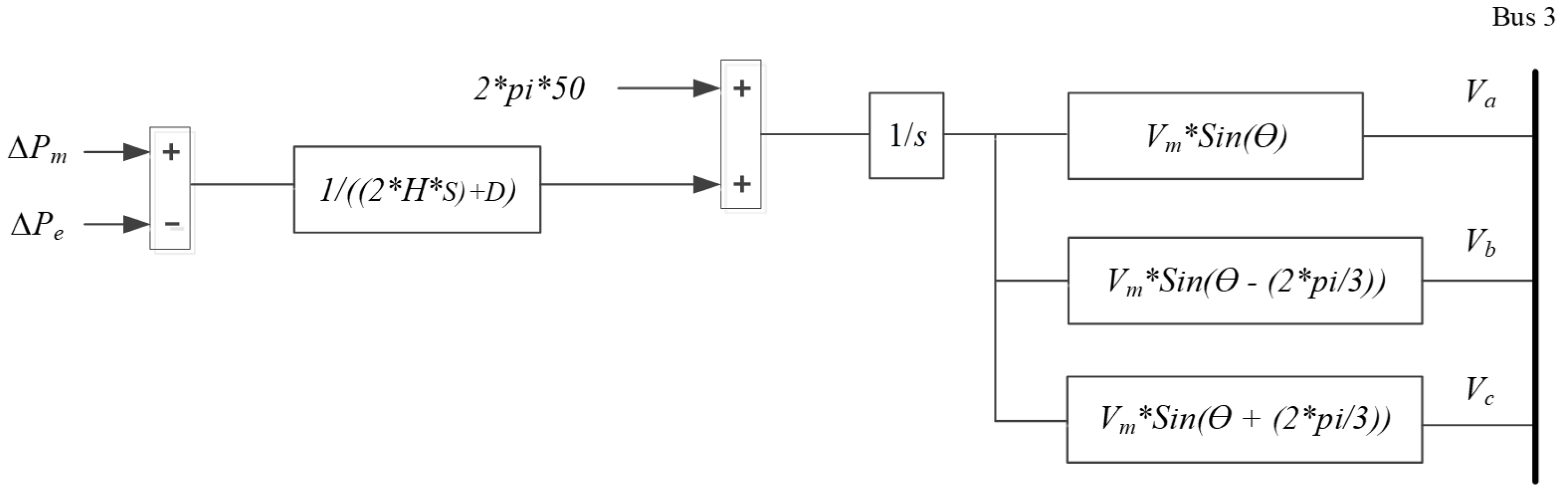
2.3. New Model for Simulation and Control

In all approaches for RES contribution to SFC, a model based exclusively on the swing equations of generators was used (see, e.g., [12]). This is based on the classic hypothesis of separation of voltage and frequency dynamics. This separation is well known and accepted in classical power systems where the classic synchronous generators are the main generation units [25].
However, due to the massive integration of the power electronics converter-based generation unit in the power system, the dynamics of voltage and frequency became very fast and in the same range. Therefore, the separation of voltage and frequency is not valid anymore for power systems with a high penetration of renewable energy sources such as the DVPP we consider here. A new model that jointly considers the dynamics of frequency and voltage at the same time was introduced in [23] and will be used here for both control and simulation purposes. This allows one to capture and, thus avoid, interactions and dynamics that might limit the real-world application of the proposed DVPP control.
Figure 3 shows our new concept for modeling in the case of one generator (renewable generator or Power Plant Module (PPM)). It consists of the full model of PPM which has to be controlled, an equivalent AC line of reactance X and a Grid Dynamic Equivalent (block GDE) which jointly provides the grid voltage and frequency. The line X accounts for the grid short-circuit power at PPM connection bus A and it is computed in a standard way (see, e.g., [26]).
In comparison with the conventional control models mentioned above, the new model with the GDE block has the benefit of capturing the dynamics of voltage and frequency at the same time. The electrical frequency at bus B is not fixed at nominal grid frequency and is determined by the GDE block, through the swing equation:
2 H d ω f d t = P G P L D u Δ ω f
and the three-phase voltage dynamics are given as:
V B a = V s i n ( θ f ) V B b = V s i n ( θ f 2 π 3 ) V B c = V s i n ( θ f + 2 π 3 ) .
H is the equivalent inertia of the rest of the system (in which the controlled PPM is inserted), P G is the global active power produced in the rest of the system and P L corresponds to the global load of the system. P m is a constant input for the PPM control problem. Dynamics (2) is stabilized by the damping factor D u and a simple integrator for deviation of ω f from the nominal grid frequency which accounts for a secondary frequency control in the rest of the system (GDE). H is computed by classic equivalencing methods (e.g., [25]) used in frequency studies.
Using a large scale classic synchronous generator instead of the GDE block is also a solution used to model the rest of the power system. However, this solution has two drawbacks: First, the voltage and frequency regulation parameters for the physical model of a classic synchronous generator would have an impact on the resulting dynamics. Second, the order of the classic synchronous generator is much higher than the one of the proposed GDE block.
Figure 4 shows the structure of the proposed control model if several PPMs have to be controlled.

3. New Control for Direct Participation of the DVPP to the SFC

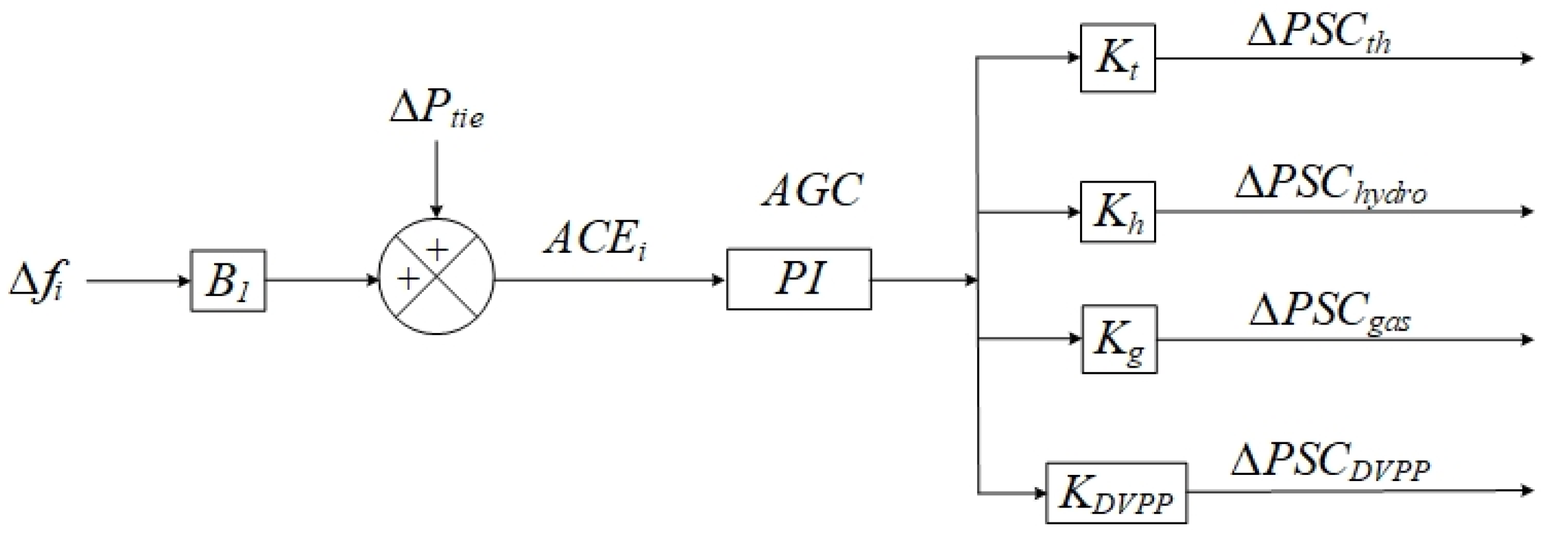
3.1. Direct Participation of the DVPP to the SFC

Figure 5 shows the proposed architecture of the control strategy which allows direct SFC participation of the DVPP. Indeed, the latter is treated in the same manner as classic synchronous generators (thermal, hydro of gas). The DVPP contributes to SFC, with a participation factor of K D V P P , on an equal basis (obligations, operation and remuneration) with classic synchronous generators. The sum of DVPP’s participation factor ( K D V P P ) and the conventional synchronous generator’s factor ( K t , K h , K g ), will be equal to 1. The participation of wind and sun RES generation is allowed by deloading primary control which provides an active power margin in the MPPT algorithm [10].
The new DVPP concept introduced in [9] allows one to jointly and optimally manage dispatchable (e.g., hydro or solar thermal plants) and non dispatchable (e.g., wind and classic solar panels) resources in order to provide predictable and reliable active power output of the DVPP in mid (few minutes) and long time horizons. This allows the DVPP to position in markets, but for full SFC integration a faster regulation level is introduced in the next section.

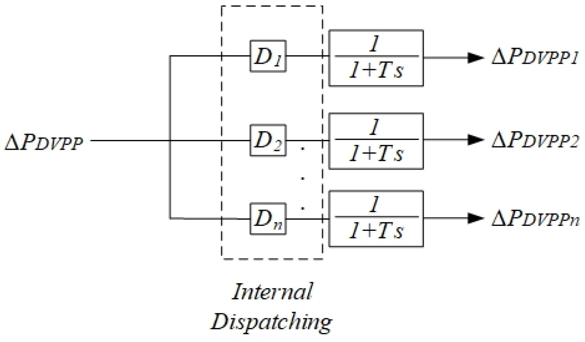
3.2. Internal DVPP Redispatch

The proposed internal redispatch is a supplementary control that allows redistribution of the contribution of each RES of the DVPP in case of rapid changes, intermittence of RES components or other variations and according to optimality criteria. More specifically, an optimal (static) computation is periodically (every 4 or 5 min) run to compute the production level for each RES generator of the DVPP and for DVPP whole participation to energy markets. This results in optimal values of the participation D i in Figure 6 and Equation (4). This participation should also be real-time adapted in case of a lack of natural resources (sun or wind) on a part of the DVPP. This is the task of the internal DVPP redispatch control level that we propose here. It is slower than the SFC dynamics and faster than the primary frequency regulation in order to not interact with the latter one. To avoid a complicated control and need of supplementary measurements, a simple internal regulation is proposed based on time-varying participation factors D i in Equation (4) which are directly evaluated from available active power measures of each RES of the DVPP. If one of the RES is limiting its output or shuts down, coefficients D i are automatically adjusted. Their sum is always 1. In order to ensure stability and non interaction with the ACE and primary dynamics, a filter with time constant T = 4 s is implemented as shown in Figure 6. This allows a DVPP internal redispatching for SFC purposes with slower dynamics than the ACE one (dozens of seconds) and faster than the primary dynamics (dozens of milliseconds). Efficacity of this choice is put into evidence in Section 4.2 by simulation tests.
Figure 6 shows the algorithm for internal dispatching of the DVPP units to contribute to SFC. P 1 , P 2 ,..., P n are the active power generated by each DVPP unit.
D 1 = P 1 P 1 + P 2 + . . . + P n D 2 = P 2 P 1 + P 2 + . . . + P n D n = P n P 1 + P 2 + . . . + P n

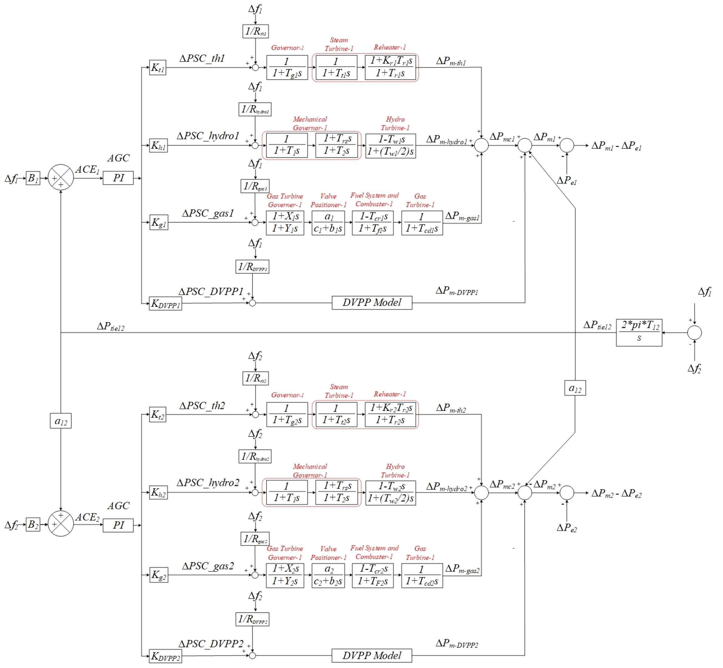
3.3. Simulation Benchmark and Control Strategy for Direct Participation of the DVPP to the SFC

Figure 7 shows the benchmark that has been implemented in Matlab/Simulink in order to test the direct participation of the DVPP to SFC. The three bus benchmark is composed of two wind turbines (WT1 and WT2) connected to bus 1 and bus 2 which plays the role of DVPP (n = 2), and a grid dynamic equivalent connected to bus 3 which provides the grid frequency and also represents the rest of power system (as discussed in Section 2.3).
Figure 8 shows the block diagram for the grid dynamic equivalent implemented based on Equations (2) and (3). The difference between the global active power produced in the system and the global load of the system ( Δ P m Δ P e ) is considered as the input for the grid dynamic equivalent block. This input is achieved through the output of control architecture brought in Figure 9.
Figure 9 shows the control model for a generic two-area power system with direct participation of DVPP to SFC. This figure considers two zones but it can be extended to stand for any number of zones. The power system in each area contains the classic synchronous generators (thermal, hydro, and gas), and DVPP. The classic synchronous generators (thermal, hydro, and gas) are mathematically modeled by transfer functions as given in [11,27]. In this paper, the two wind turbines type IV (PMSG-based wind turbine model) are modeled in detail to take into account the role of DVPP and all dynamic interactions. Notice that the modeling adopted here allows all the dynamics, including the grid voltage one, the DVPP generators primary ones and the rapid ones of the power electronics which connect the DVPP generators to the grid (Figure 7), and not only the frequency dynamics as in previous SFC work in the literature (e.g., [11,12]). Indeed, in our model, the full model of real PMSG machines have been taken into account, and all the other primary controls for both frequency (including both fast control and very fast control (RoCoF)) and voltage are considered. Standard vector controls have been adopted for these loops. Since we considered the real model of the machines, it is possible to consider the primary dynamics for voltage. On the grid side, the model mentioned in Section 2.3 provides mixed voltage and frequency dynamics.
As it can be observed from Figure 9, DVPP directly participates to SFC, in the same manner as classic synchronous generators (the concept is shown in Figure 5). The area control error of each zone will be regulated to zero by an effort shared among the classic synchronous generators and the DVPP’s ones with participation factors of K t , K h , K g , K D V P P as discussed in Section 3.1.

4. Simulation Results

The simulation results are given in this section for direct participation of the DVPP to the SFC, tested on the benchmark represented in Figure 7 and implemented in Matlab/Simscape. It should be noted that a DVPP is only considered in one area (area 1) of Figure 9. Therefore, in the control model shown in Figure 9, three classic equivalent synchronous generators (thermal, hydro, and gas) and two detailed PMSG-based wind turbines (representing DVPP, n = 2) have been used in area 1. The grid frequency is provided by the grid dynamic equivalent block shown in Figure 8. Area 2 contains only three classic equivalent generators (thermal, hydro, and gas).
The inputs to the SFC loop are the area control errors related to area 1 and area 2 (ACE1, ACE2).
DVPP participation is tested in two situations: nominal run where all DVPP generators are normally (as scheduled) operating and disturbed situations in which some generators of the DVPP are lost (due to, for example, lack of natural resources—wind in our case—on some part of the DVPP) and internal DVPP redispatch is acting. In this section, some other disturbances currently considered in power systems analysis, such as grid short-circuits, are also considered.

4.1. Nominal Scenarios

As illustrated in Figure 9, the DVPP directly participates to SFC. In the nominal mode, the load of the area 1 in the benchmark is 100 MW. The two PMSG-based wind turbines have a rated power of 4.1 MW, each of them working in deloaded operation (at 3.5 MW), in order to provide a reserve for frequency support.
An under frequency event has been considered as a case study to test the SFC strategy. At t = 40 s, the active power of the load in the area 1 is increased by 6 percent (to 106 MW), causing the under frequency deviation shown in Figure 10.
It is assumed that 90 percent of frequency support will be provided by the classic synchronous generators, and 10 percent of frequency support will be provided by the DVPP. Therefore, the participation factors in Figure 5 are considered 0.1 for DVPP, and 0.3 for thermal, hydro and gas synchronous generation units.
Figure 11 and Figure 12 show the active power generated by the classic synchronous generators (thermal, hydro and gas) and the DVPP (PW1 + PW2: the sum of active power generated by the two PMSG-based wind turbines), respectively.
As it can be observed from Figure 11 and Figure 12, the classic synchronous generators and the DVPP will participate directly to SFC by increasing their power by 5.4 MW and 0.6 MW, respectively.
One can also notice nominal frequency response, compliant with the classic specifications of the SFC (Figure 10).
The internal dispatching algorithm ensures that each WT will contribute to frequency support regarding its generating active power as given in Equation (4). Therefore, as it can be observed from Figure 13, both wind turbines will work at the deloaded mode (PW1 = PW2 = 3.5 MW) until t = 40 s. At t = 40 s, both wind turbines increase their power to provide the 10 percent of total active power required for SFC support (5 percent will be provided by each wind turbine).
Figure 14 shows the three phase voltages at bus 3 of the benchmark. It is worth mentioning that the amplitude of the voltage is constant at 1 per unit, while the frequency reduces due to the load increase, which can be observed from Figure 10.

4.2. Behavior in Case of Disturbances

4.2.1. Influence of Internal Redispatch

In order to test the participation of the DVPP as a whole unit in provision of active power for secondary frequency support, at t = 80 s it is supposed that wind turbine number 2 goes out of service. The internal redispatch regulation introduced in Section 3.2 will transfer to wind turbine number 1 all required SFC support (10 percent of total active power required for SFC support) (Figure 13). As it can be observed from Figure 15, at t = 80 s, this internal redispatch has very little influence on the frequency dynamics.
It should be noted that the internal redispatch algorithm introduced in Section 3.2 works in the sense that it transfers the regulation effort to the remaining WT1 in order to maintain the full participation of DVPP in secondary frequency support. However, in the case treated here, the DVPP participation is limited by the predefined deloading margin of WT2. The latter increases its production in order to compensate the loss of WT1 but the total active power generated by DVPP decreases by 3.5 MW when WT2 goes out of service. This amount of active power is compensated by the classic generators via the AGC classic loop, as it can be observed from Figure 11.

4.2.2. Interaction between SFC Zones

In order to study dynamic interactions of the two area controls, along with the under frequency event in area 1, an under frequency event is also simulated (at t = 40 s) in area 2 by increasing the active power of the load in this area by 10 percent. This is rejected in the steady state in area 2 as shown in Figure 15 (response to the event at t = 40 s).
Figure 16 and Figure 17 give the ACEs related to area 1 and area 2, respectively. As it can be observed from these figures, our proposed strategy efficiently eliminates the area control error in both areas.
Figure 18 shows the tie-line power between the two areas. The reference for this is tracked without steady-state error for all studied scenarios, including disturbances.

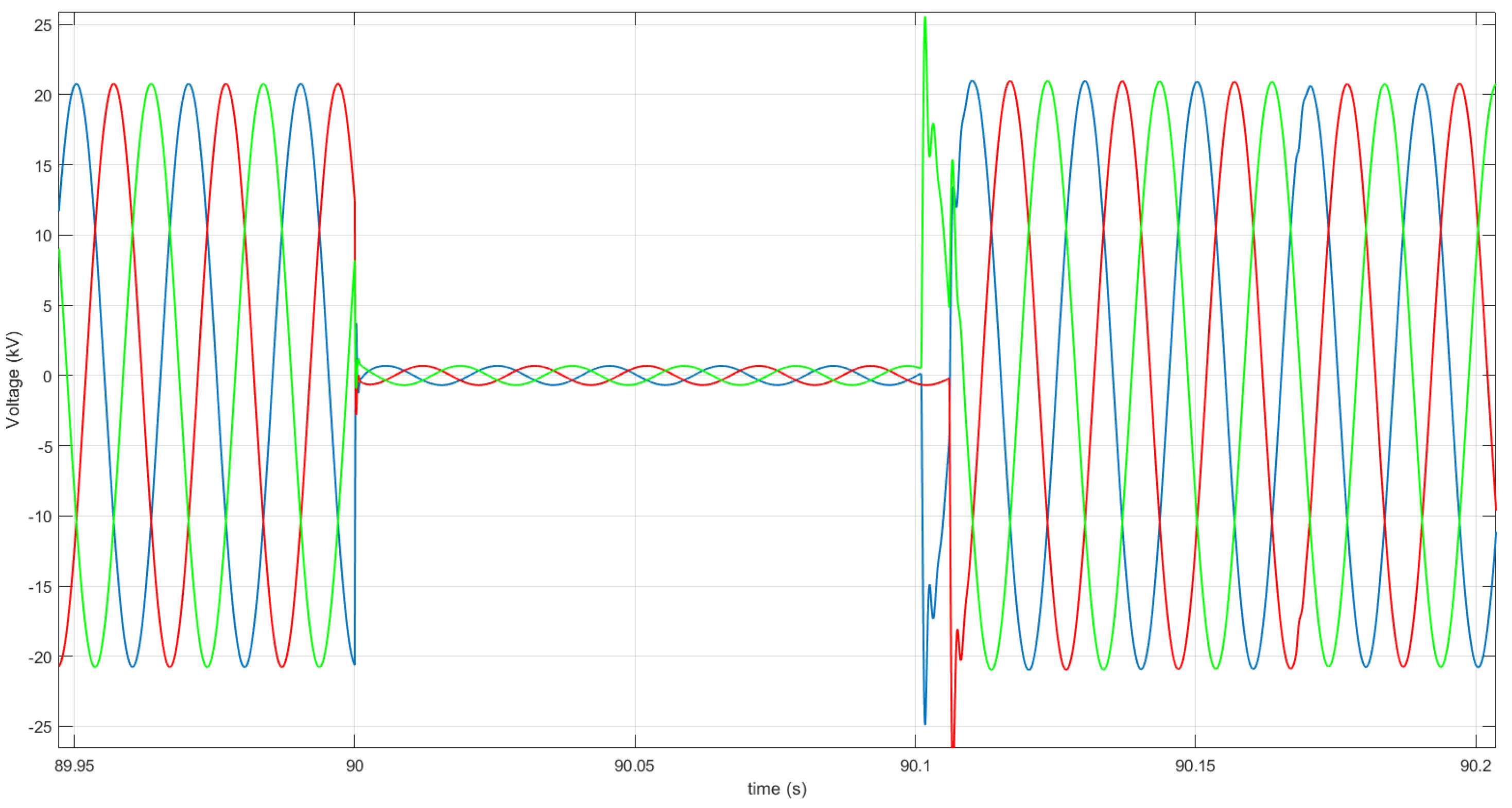
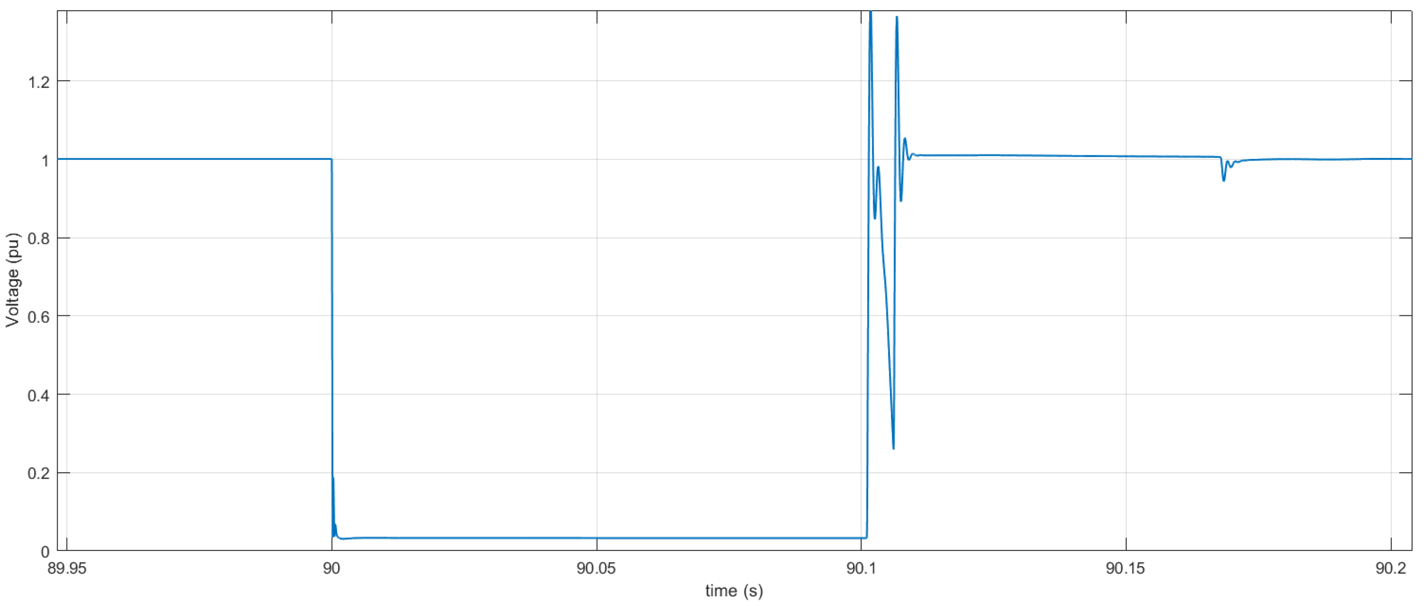
4.2.3. Short-Circuit Test

A short-circuit test is considered here to analyze the control response in the case of large disturbances which also excite faster—voltage and frequency primary—dynamics. Filters introduced in Figure 6 are intended to avoid bad interactions with such faster control loops.
Figure 19 shows the active power of WTs and their sum when a 100 ms duration three phase short circuit occurs at t = 90 s at bus 1, which is the grid connection point of WT1 (Figure 7). As it can be observed from this figure, the active power smoothly returns to its steady-state value after the short-circuit fault is cleared.
Moreover, Figure 20 and Figure 21 show the response of the voltage (3 phase and rms) of bus 1 to the considered short-circuit. One can notice no interaction with the primary voltage and frequency dynamics. This is due to the design of the internal redispatch filter (1/1 + 4 s) shown in Figure 6. More specifically, the time constant of this filter is chosen to separate in the frequency band the SFC response from the ones of the primary control loops. Notice that, as explained in Section 2.3, a new model to represent mixed voltage and frequency dynamics is used in comparison to past approaches and studies for the SFC. This allows us to ensure the lack of interactions with rapid dynamics of power electronics and fast loops of classic synchronous generators at both synthesis and validation levels.

5. Conclusions

In this paper, the direct participation of DVPPs for the provision of secondary frequency support has been studied. A new SFC control strategy is proposed in which DVPPs are fully participating in the same manner as classic synchronous generators.
Furthermore, an internal redispatching control algorithm is proposed to deal with inherent intermittence due to natural resources (sun or wind) variations and accidental failures inside the DVPP. In such a way, one could ensure reliable full participation to SFC of the whole DVPP as a single equivalent unit from both points of view of dynamic control and regulatory/market participation to frequency grid service.
The whole control is proven to also be robust against regular disturbances of a power system (such as short-circuits) and not to interact with more rapid dynamics of power electronics via which the renewable generators (of the DVPP or outside) are connected to the grid or with neighbor classic synchronous generators (involved or not into the SFC).
Simulation results have been performed on a two area power system to prove the effective performance of the proposed SFC control strategy in provision of frequency support. These simulations are realistic from several points of view:
  • They consider a detailed model of the DVPP generators (PMSG machines in the example treated here);
  • The grid dynamics model integrates both voltage and frequency dynamics;
  • Two SFC zones are considered to incorporate the tie-lines power exchange regulation and to consider dynamic interactions at all levels (frequency/time-domains) between the SFC zones.
All the latter points are original in the integration of renewables in the SFC. The global contribution of the work is thus to provide a robust dynamic control which allows one to easily integrate the DVPP in actual frameworks. More specifically, the proposed approach is compliant—in the sense that it is part of a hierarchical time-decoupling strategy which includes all actions from primary to secondary controls—with the standard SFC control for classic generators and also with the static optimization level proposed for the DVPP in [9,21,22] (and further developed in forthcoming papers) for optimal energy and profit run of the DVPP at both the local and energy market participation levels.
Future extensions of this work will be performed to consider more detailed DVPPs (with more than two generators and specific topologies (e.g., with RES generators also connected to distribution grids)), as well as hardware in the loop validations of the resulting control.

Author Contributions

B.M. contributed for the concepts proposals and text writing and reviewing. M.E.A. contributed for proving the concepts, developping the models, validation tests and text writing. All authors have read and agreed to the published version of the manuscript.

Funding

This project has received funding from the European Union’s Horizon 2020 research and innovation programme under grant agreement No. 883985 (POSYTYF—POwering SYstem flexibiliTY in the Future through RES, https://posytyf-h2020.eu/.

Institutional Review Board Statement

Not applicable.

Informed Consent Statement

Not applicable.

Data Availability Statement

Not applicable.

Conflicts of Interest

The authors declare no conflict of interest.

References

  1. Wang, S.; Tomsovic, K. A Novel Active Power Control Framework for Wind Turbine Generators to Improve Frequency Response. IEEE Trans. Power Syst. 2018, 33, 6579–6589. [Google Scholar] [CrossRef]
  2. Díaz-González, F.; Hau, M.; Sumper, A.; Gomis-Bellmunt, O. Participation of wind power plants in system frequency control: Review of grid code requirements and control methods. Renew. Sustain. Energy Rev. 2014, 34, 551–564. [Google Scholar] [CrossRef]
  3. Miller, N.W.; Clark, K.; Shao, M. Frequency responsive wind plant controls: Impacts on grid performance. In Proceedings of the 2011 IEEE Power and Energy Society General Meeting, Detroit, MI, USA, 24–28 July 2011. [Google Scholar]
  4. Singhvi, V.; Pourbeik, P.; Bhatt, N.; Brooks, D.; Zhang, Y.; Gevorgian, V.; Ela, E.; Clark, K. Impact of Wind Active Power Control Strategies on Frequency Response of an Interconnection. In Proceedings of the IEEE Power & Energy Society General Meeting, Vancouver, BC, Canada, 21–25 July 2013. [Google Scholar]
  5. Murali, S.; Shankar, R. Optimal CC-2DOF(PI)-PDF controller for LFC of restructured multi-area power system with IES-based modified HVDC tie-line and electric vehicles. Eng. Sci. Technol. Int. J. 2022, 32, 101058. [Google Scholar] [CrossRef]
  6. Sharma, P.; Mishra, A.; Saxena, A.; Shankar, R. A Novel Hybridized Fuzzy PI-LADRC Based Improved Frequency Regulation for Restructured Power System Integrating Renewable Energy and Electric Vehicles. IEEE Access 2021, 9, 7597–7617. [Google Scholar] [CrossRef]
  7. Murali, S.; Shankar, R. Impact of Inertia Emulation Based Modified HVDC Tie-Line for AGC Using Novel Cascaded Fractional Order Controller in Deregulated Hybrid Power System. J. Electr. Eng. Technol. 2021, 16, 1219–1239. [Google Scholar] [CrossRef]
  8. Rebours, Y.G.; Kirschen, D.S.; Trotignon, M.; Rossignol, S. Survey of Frequency and Voltage Control Ancillary Services—Part I: Technical Features. IEEE Trans. Power Syst. 2007, 22, 350–357. [Google Scholar] [CrossRef]
  9. Marinescu, B.; Gomis-Bellmunt, O.; Dörfler, F.; Schulte, H.; Sigrist, L. Dynamic Virtual Power Plant: A New Concept for Grid Integration of Renewable Energy Sources. arXiv 2021, arXiv:2108.00153. [Google Scholar]
  10. Zhang, X.; Chen, Y.; Wang, Y.; Zha, X.; Yue, S.; Cheng, X.; Gao, L. Deloading power coordinated distribution method for frequency regulation by wind farms considering wind speed differences. IEEE Access 2019, 7, 122573–122582. [Google Scholar] [CrossRef]
  11. Oshnoei, A.; Khezri, R.; Muyeen, S.M.; Blaabjerg, F. On the Contribution of Wind Farms in Automatic Generation Control: Review and New Control Approach. Appl. Sci. 2018, 8, 1848. [Google Scholar] [CrossRef] [Green Version]
  12. Bevrani, H.; Golpîra, H.; Messina, A.R.; Hatziargyriou, N.; Milano, F.; Ise, T. Power system frequency control: An updated review of current solutions and new challenges. Electr. Power Syst. Res. 2021, 194, 107114. [Google Scholar] [CrossRef]
  13. Liu, Y.; Jiang, L.; Wu, Q.H.; Zhou, X. Frequency control of DFIG-based wind power penetrated power systems using switching angle controller and AGC. IEEE Trans. Power Syst. 2017, 32, 1553–1567. [Google Scholar] [CrossRef] [Green Version]
  14. Pradhan, C.; Bhende, C.N. Frequency sensitivity analysis of load damping coefficient in wind farm-integrated power system. IEEE Trans. Power Syst. 2017, 32, 1016–1029. [Google Scholar]
  15. Zhang, Y.; Liu, X.; Yan, Y. Model predictive control for load frequency control with wind turbines. J. Control. Sci. Eng. 2015, 2015, 49. [Google Scholar] [CrossRef]
  16. Zhang, Y.; Liu, X.; Qu, B. Distributed model predictive load frequency control of multi-area power system with DFIGs. IEEE/CAA J. Autom. Sin. 2017, 4, 125–135. [Google Scholar] [CrossRef]
  17. Nguyen Duc, H.; Nguyen Hong, N. Optimal Reserve and Energy Scheduling for a Virtual Power Plant Considering Reserve Activation Probability. Appl. Sci. 2021, 11, 9717. [Google Scholar] [CrossRef]
  18. Iria, J.; Soares, F. Real-time provision of multiple electricity market products by an aggregator of prosumers. Appl. Energy 2019, 255, 113792. [Google Scholar] [CrossRef]
  19. Nguyen-Duc, H.; Nguyen-Hong, N. A study on the bidding strategy of the Virtual Power Plant in energy and reserve market. Energy Rep. 2020, 6 (Suppl. 2), 622–626. [Google Scholar] [CrossRef]
  20. Iria, J.; Soares, F.; Matos, M. Optimal bidding strategy for an aggregator of prosumers in energy and secondary reserve markets. Appl. Energy 2019, 238, 1361–1372. [Google Scholar] [CrossRef]
  21. Oladimeji, O.; Ortega, A.; Sigrist, L.; Sanchez-Martin, P.; Lobato, E.; Rouco, L. Modeling Demand Flexibility of RES-based Virtual Power Plants. arXiv 2021, arXiv:2112.03261. [Google Scholar]
  22. Oladimeji, O.; Ortega, A.; Sigrist, L.; Sanchez-Martin, P.; Lobato, E.; Rouco, L. Optimal Participation of Heterogeneous, RES-based Virtual Power Plants in Energy Markets. arXiv 2021, arXiv:2112.02200. [Google Scholar]
  23. Marinescu, B.; Kamal, E.; Ngo, H.-T. A System Model-Based Approach for the Control of Power Park Modules for Grid Voltage and Frequency Services. arXiv 2021, arXiv:2107.02000. [Google Scholar]
  24. Alhelou, H.H.; Hamedani-Golshan, M.E.; Zamani, R.; Heydarian-Forushani, E.; Siano, P. Challenges and Opportunities of Load Frequency Control in Conventional, Modern and Future Smart Power Systems: A Comprehensive Review. Energies 2018, 11, 2497. [Google Scholar] [CrossRef] [Green Version]
  25. Kundur, P. Power Systems Stability and Control; EPRI: Washington, DC, USA, 1994. [Google Scholar]
  26. Xiong, X.; Ouyang, J.; Jin, J. Calculation of steady-state short-circuit current of wind turbines with doubly fed induction generator. In Proceedings of the IEEE International Conference on Advanced Power System Automation and Protection, Beijing, China, 16–20 October 2011; Volume 3, pp. 1782–1788. [Google Scholar]
  27. Pathak, N.; Bhatti, T.S.; Verma, A. Accurate modelling of discrete AGC controllers for interconnected power systems. IET Gener. Transm. Distrib. 2017, 11, 2102–2114. [Google Scholar] [CrossRef]
Figure 1. Control block diagram for automatic generation control (AGC).
Energies 15 02775 g001
Figure 2. Indirect participation of DVPPs in SFC.
Energies 15 02775 g002
Figure 3. New model for single PPM.
Energies 15 02775 g003
Figure 4. New control model for multiple PPMs.
Energies 15 02775 g004
Figure 5. Direct participation of DVPPs in SFC.
Energies 15 02775 g005
Figure 6. Internal dispatching of the DVPP for participation to the SFC.
Energies 15 02775 g006
Figure 7. The benchmark to test the control strategies.
Energies 15 02775 g007
Figure 8. Block diagram for dynamic v/f equivalent of the rest of power.
Energies 15 02775 g008
Figure 9. New control model for direct participation of the DVPP to a two-area SFC.
Energies 15 02775 g009
Figure 10. The Frequency of area 1.
Energies 15 02775 g010
Figure 11. The active power generated by conventional synchronous generators units in the area 1.
Energies 15 02775 g011
Figure 12. The active power generated by DVPP unit.
Energies 15 02775 g012
Figure 13. The active power of each PMSG-based WT.
Energies 15 02775 g013
Figure 14. Three phase voltages at bus 3 of the benchmark.
Energies 15 02775 g014
Figure 15. Frequency waveform in the area 2.
Energies 15 02775 g015
Figure 16. The area control error of area 1.
Energies 15 02775 g016
Figure 17. The area control error of area 2.
Energies 15 02775 g017
Figure 18. The tie-line power between two areas.
Energies 15 02775 g018
Figure 19. Active power of WTs and their sum in response to the three phase short-circuit.
Energies 15 02775 g019
Figure 20. Voltage at bus 1 in response to the three phase short-circuit.
Energies 15 02775 g020
Figure 21. rms value of voltage at bus 1 in response to the three phase short-circuit.
Energies 15 02775 g021
Publisher’s Note: MDPI stays neutral with regard to jurisdictional claims in published maps and institutional affiliations.

