
A Review of Engine’s Performance When Supercharging by a Pressure Wave Supercharger


Abstract
:1. Introduction
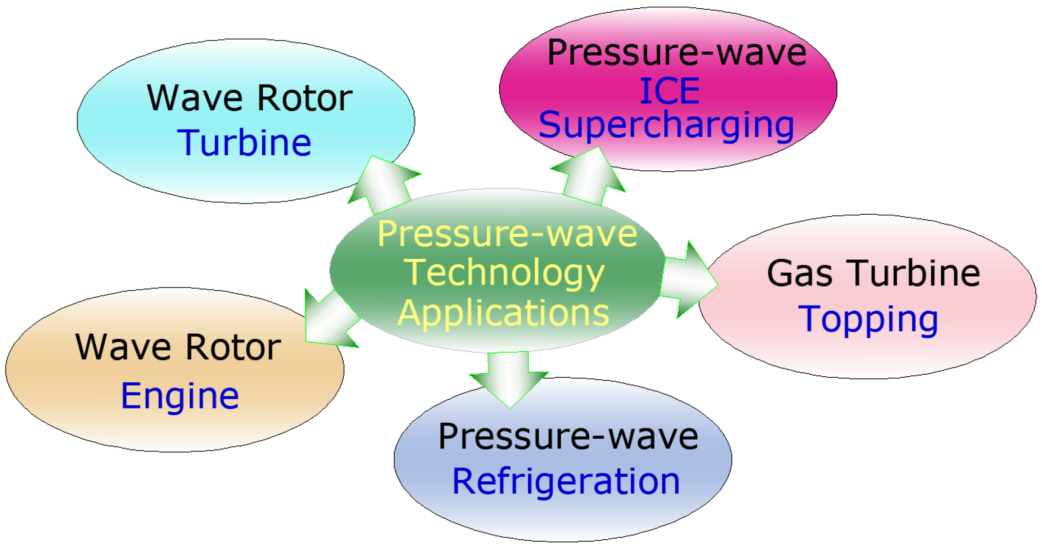
2. Pressure Wave Technology
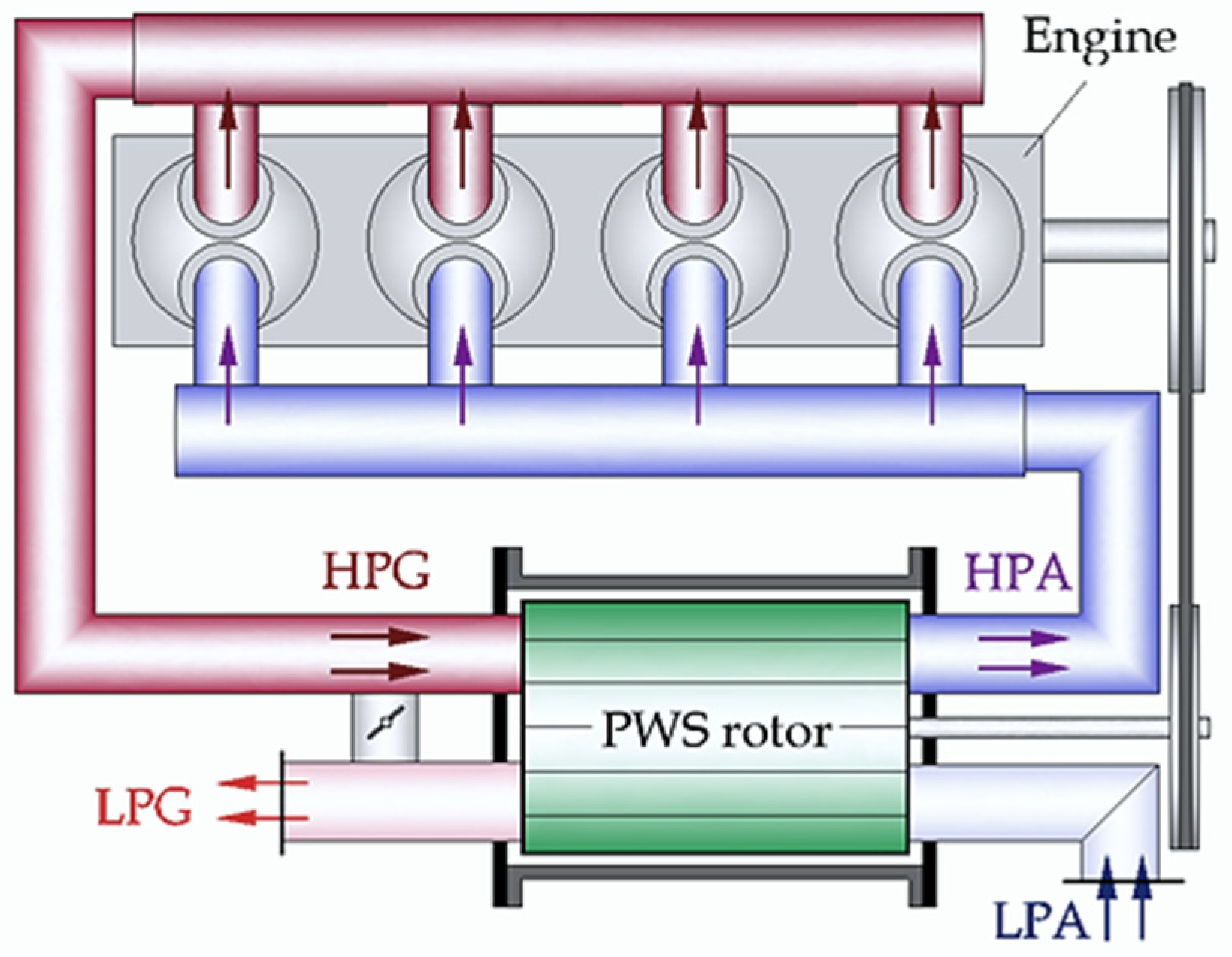
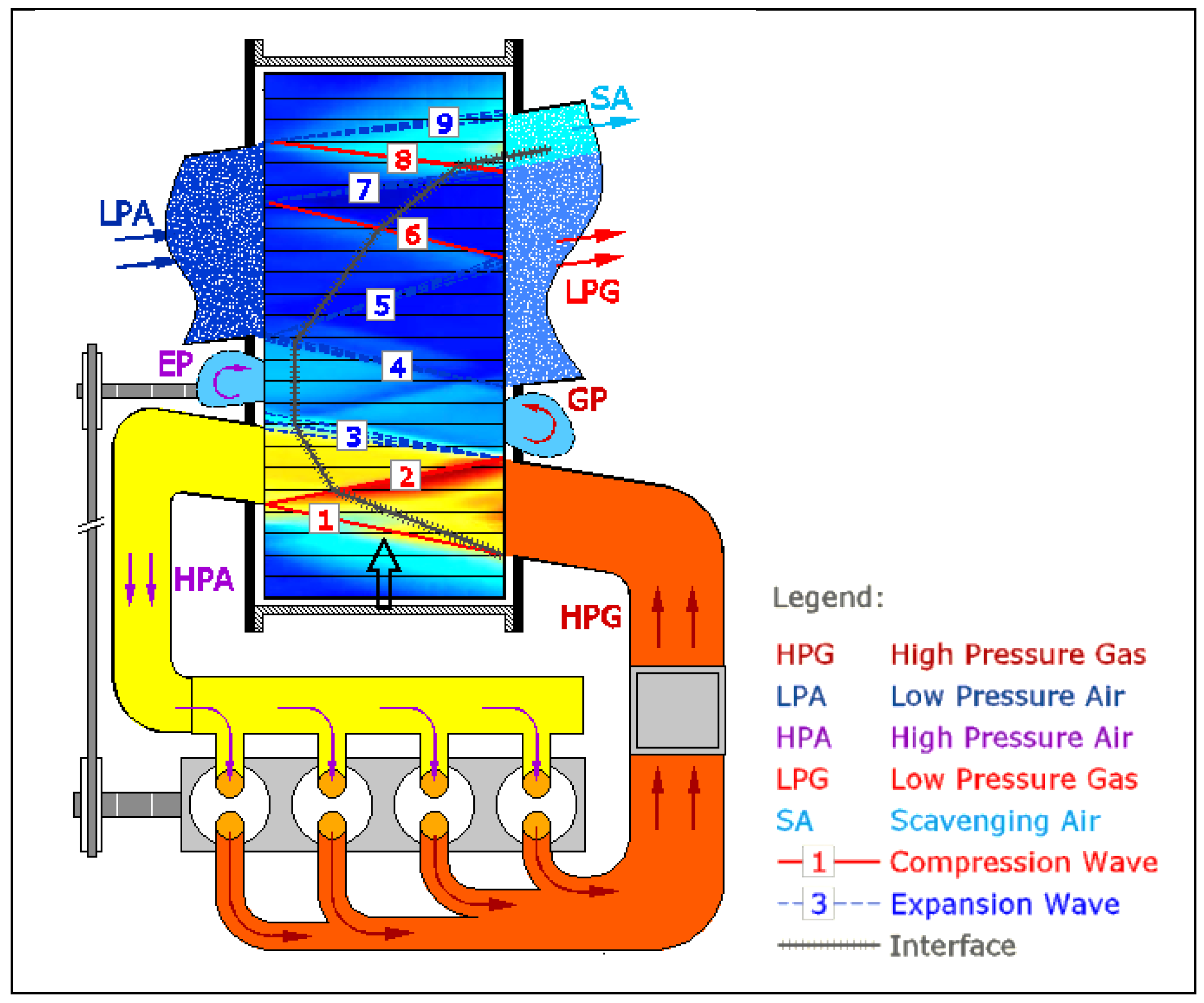
3. Operating Principles

4. PWS General Performance and Its Limitations
4.1. Emissions
- The FTP composite results were:
- -
- 0.16 g/km HC for 220 D-CX and 0.13 g/km HC for 240 D, lower than the 1978 Federal Statutory Emission Standard (FSES) of 0.25 g/km,
- -
- 0.84 g/km CO for 220 D-CX and 0.72 g/km CO for 240 D, lower than the 1978 FSES of 2.1 g/km,
- -
- 0.86 g/km NOx for 220 D-CX and 0.96 g/km NOx for 240 D, lower than 1977 FSES of 1.24 g/km but higher than 1978 FSES of 0.25 g/km,
- -
- 252 g/km CO2 for 220 DCX and 254 g/km CO2 for standard 240 D;
- The HFTP results were as follows:
- -
- 0.07 g/km HC for 220 D-CX and 0.06 g/km HC for 240 D,
- -
- 0.47 g/km CO for 220 D-CX and 0.41 g/km CO for 240 D,
- -
- 0.75 g/km NOx for 220 D-CX and 0.90 g/km NOx for 240 D,
- -
- 184 g/km CO2 for 220 D-CX and 194 g/km CO2 for the standard 240 D.
- According to FTP Mass Emissions: 0.28 g/km HC, 1.025 g/km CO, 206.3 g/km CO2, 0.60 g/km NOx, 0.17 g/km particulates of which ~3.4% sulfate particulates;
- According to the HFET Mass Emissions procedure: 0.068 g/km HC, 0.36 g/km CO, 244 151.6 g/km CO2, 0.41 g/km NOx, 0.085 g/km particulates of which ~5.2% sulfate particulates.
4.2. Noise
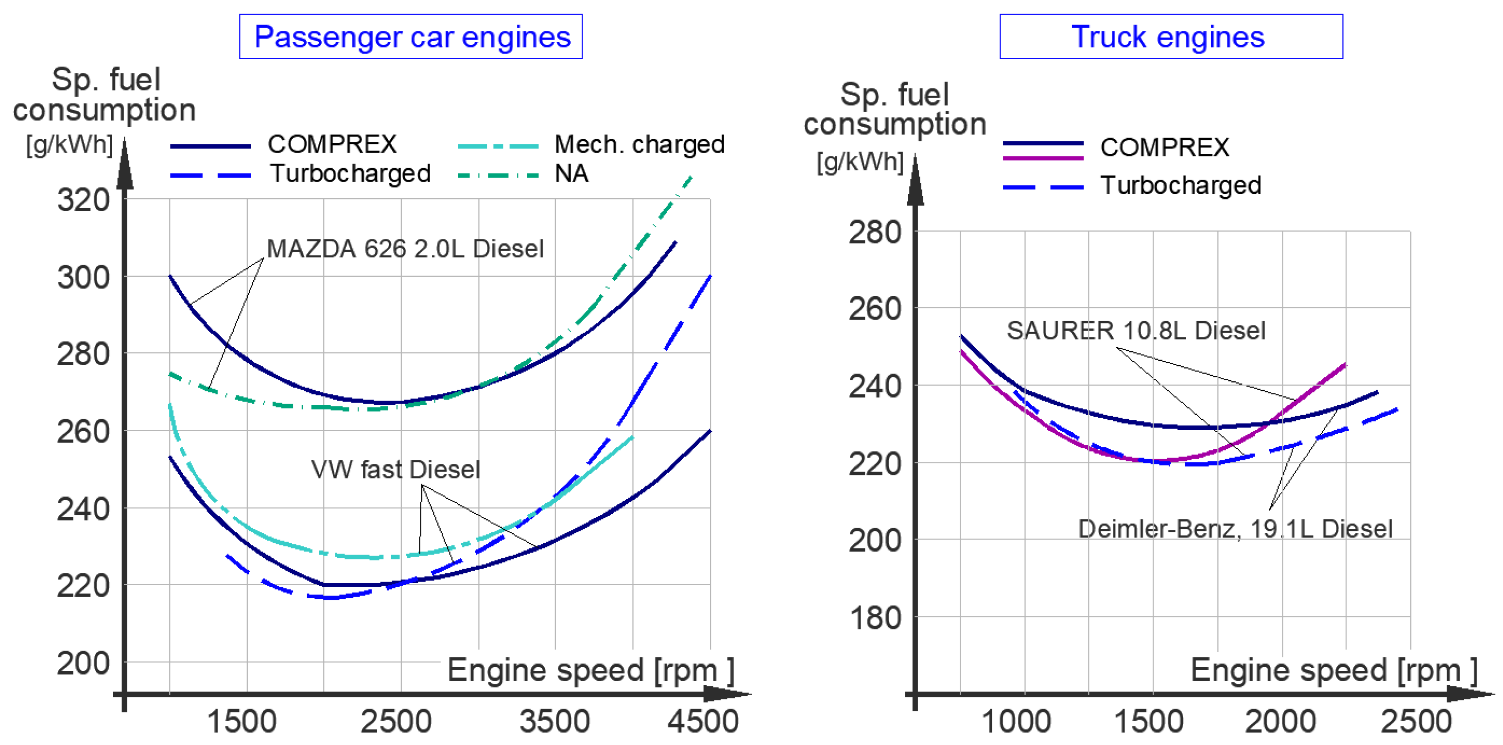
4.3. Fuel Consumption
- -
- 9.43 L/100 km for 220 D-CX and 9.52 for 240 D as a composite result;
- -
- 8.2 L/100 km for 220 D-CX and 8.7 L/100 km for 240 D for the Highway fuel consumption.
- -
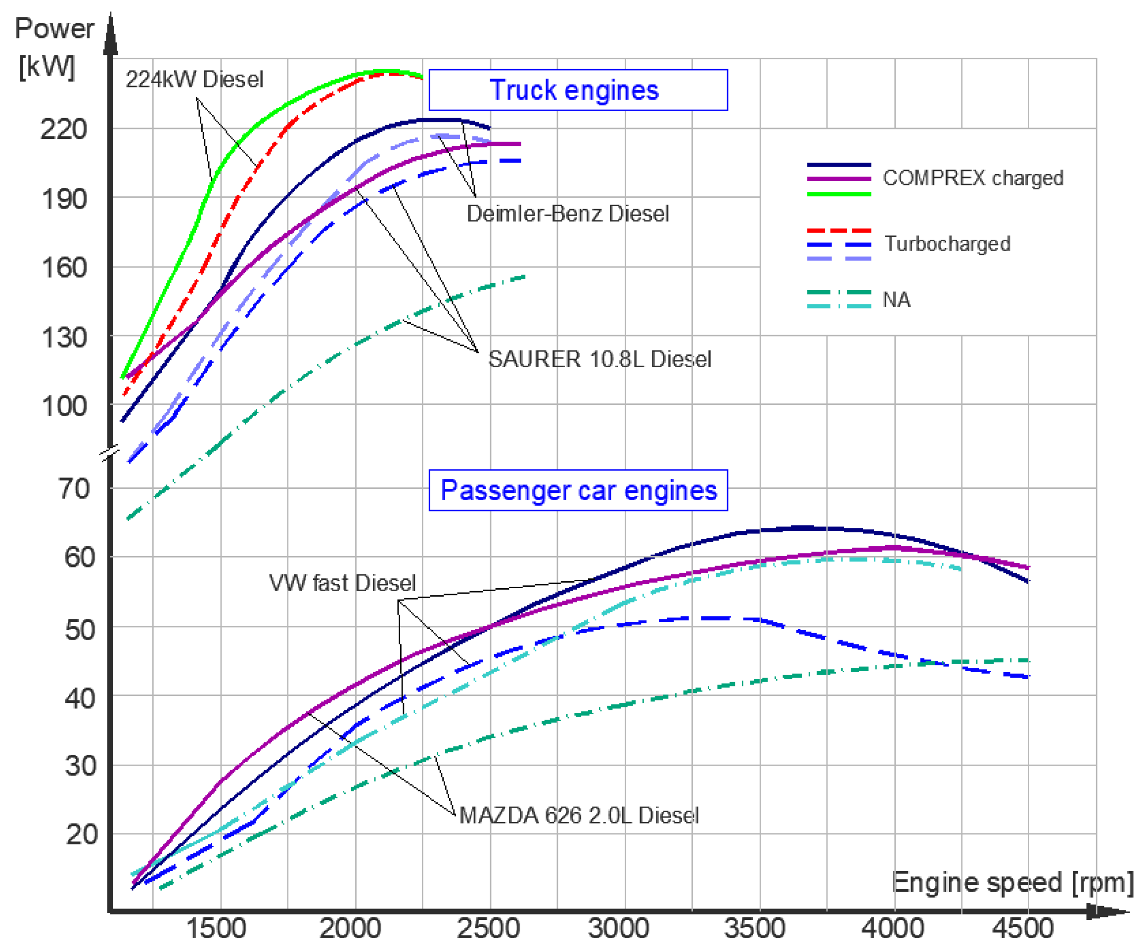
- For passenger cars, the lowest value recorded was 270 g/kWh at about 2000 rpm for the Mazda 626 2.0 L engine, or 220 g/kWh at 2000 rpm for the VW fast diesel. It can be seen that turbocharging seems to get lower values at low engine speeds, while at high speeds Comprex has better results;
- -
- For truck engines, the pressure wave supercharging led to a fuel specific consumption of about 220 g/kWh for the Saurer 10.8 L diesel engine reached at 1250 rpm, or 230 g/kWh at 1500 rpm for the Daimler-Benz 19.1 L diesel engine.
5. Conclusions
Author Contributions
Funding
Institutional Review Board Statement
Informed Consent Statement
Conflicts of Interest
References
- Nalim, R.; Li, H.; Akbari, P. Air-standard aerothermodynamic analysis of gas turbine engines with wave rotor combustion. In Proceedings of the ASME Turbo Expo 2009, Orlando, FL, USA, 8–12 June 2009; pp. 445–456. [Google Scholar]
- Snyder, P.H.; Nalim, M.R. Pressure Gain Combustion Application to Marine and Industrial Gas Turbines. In Proceedings of the ASME Turbo Expo 2012, Copenhagen, Denmark, 11–15 June 2012; Volume 5, pp. 409–422, ISBN 978-0-7918-4471-7. [Google Scholar]
- Nagashima, T.; Okamoto, K.; Ribaud, Y. Cycles and Thermal System Integration Issues of Ultra-Micro Gas Turbines. In RTO Educational Notes, Micro Gas Turbines; RTO-EN-AVT-131; NATO Research and Technology Organisation: Neuilly-sur-Seine, France, 2005; pp. 1–66. [Google Scholar]
- Akbari, P.; Nalim, R.; Müller, N. Performance enhancement of microturbine engines topped with wave rotors. J. Eng. Gas Turbines Power 2006, 128, 190–202. [Google Scholar] [CrossRef] [Green Version]
- Pearson, R.D. A gas wave-turbine engine which developed 35 HP and performed over a 6:1 speed range. In Proceedings of the ONR/NAVAIR Wave Rotor Research and Technology Workshop, Monterey, CA, USA, 1 January–31 March 1985. [Google Scholar]
- Costiuc, I.; Chiru, A. Evolution of the Pressure Wave Supercharger Concept. IOP Conf. Ser. Mater. Sci. Eng. 2017, 252, 12081. [Google Scholar] [CrossRef] [Green Version]
- Smith, B.D.; Polanka, M.D.; Paxson, D.E.; Hoke, J.L. Scaling study of wave rotor turbo normalization of an internal combustion engine. In Proceedings of the 48th AIAA/ASME/SAE/ASEE Joint Propulsion Conference and Exhibit, Atlanta, GA, USA, 30 July–1 August 2012. [Google Scholar]
- Zhao, J.Q.; Hu, D.P.; Liu, P.Q.; Liu, F.X.; Gao, J.J. Thermodynamic analysis of a novel wave rotor refrigeration cycle. Adv. Mater. Res. 2013, 805–806, 537–542. [Google Scholar] [CrossRef]
- Hu, D.; Li, R.; Liu, P.; Zhao, J. The loss in charge process and effects on performance of wave rotor refrigerator. Int. J. Heat Mass Transf. 2016, 100, 497–507. [Google Scholar] [CrossRef]
- Berchtold, M. The Comprex Diesel Supercharger. SAE Trans. 1959, 67, 5–14. [Google Scholar]
- Weaving, J.H. Internal Combustion Engineering, Science and Technology; Elsevier Science Publishers Ltd.: Dordrecht, The Netherlands, 1990; ISBN 978-94-010-6822-2. [Google Scholar]
- Costiuc, I.; Chiru, A.; Costiuc, L. Pressure Wave Technology—An interesting approach in supercharging. Rom. J. Tech. Sci. Appl. Mech. 2018, 63, 50–73. [Google Scholar]
- Society of Automotive Engineers. Automotive Handbook, 3rd ed.; Society of Automotive Engineers (SAE): Warrendale, PA, USA, 1993; ISBN 1-56091-372-X. [Google Scholar]
- Pranav, A.S. Wave Rotor Test Rig Design Procedure for Gas Turbine Enhancement; ProQuest: Ann Arbor, MI, USA, 2008. [Google Scholar]
- Akbari, P.; Nalim, R.; Mueller, N. A Review of Wave Rotor Technology and its Applications. J. Eng. Gas Turbines Power 2006, 128, 717–735. [Google Scholar] [CrossRef] [Green Version]
- Azoury, P.H. An Introduction to the Dynamic Pressure Exchanger. Proc. Inst. Mech. Eng. 1965, 180, 451–480. [Google Scholar] [CrossRef]
- Berchtold, M.; Gull, H.P. Road Performance of a Comprex Supercharged Diesel Truck. SAE Trans. 1960, 68, 367–379. [Google Scholar]
- Berchtold, M. Pressure wave charging for small vehicle diesel engines. Schweiz. Bauztg. 1961, 46, 801–809. [Google Scholar]
- Wunsch, A. Charging vehicle diesel engines with the exhaust gas turbocharger and the Comprex pressure wave machine. Mot. Z. 1990, 1, 19. [Google Scholar]
- Berchtold, M. The COMPREX. In Proceedings of the 1985 ONR/NAVAIR Wave Rotor Research and Technology Workshop, Naval Postgraduate School, Monterey, CA, USA, 1 January–31 March 1985. [Google Scholar]
- Gygax, J.; Schneider, G. Operating experiences with the Comprex pressure wave supercharger in the Opel Senator. MTZ-Mot. Z. 1988, 9, 335–340. [Google Scholar]
- Zehnder, G.W.; Mayer, A. Comprex® Pressure-Wave Supercharging for Automotive Diesels-State-of-the-Art. SAE Trans. 1984, 93, 756–771. [Google Scholar]
- Schruf, G.M.; Kollbrunner, T.A. Application and Matching of the Comprex Pressure-Wave Supercharger to Automotive Diesel Engines; SAE Technical paper 840133; SAE: Warrendale, PA, USA, 1985; ISSN 0148-7191. [Google Scholar]
- Kollbrunner, T.A. Comprex Supercharging for Passenger Diesel Car Engines; SAE Paper 800884; SAE: Warrendale, PA, USA, 1981; ISSN 0148-7191. [Google Scholar]
- Leahu, C. Optimisation of Compression Ignition Engine using Supercharging Systems. Ph.D. Thesis, University Transilvania Brasov, Brasov, Romania, 2011. [Google Scholar]
- Hinchey, J.J.; Sweek, R.P. A Study of Gas Flow in the “Comprex” by a Hidraulic Analogy. Master’s Thesis, Massachusetts Institute of Technology, Cambridge, MA, USA, 1948. [Google Scholar]
- Klapproth, J.F.; Ullman, G.; Tysl, E. NACA Research Memorandum—Performance of an Impulse-Type Supersonic Compressor with Stators; Lewis Flight Propulsion Laboratory: Cleveland, OH, USA, 1952. [Google Scholar]
- Tysl, E.; Klapproth, J.F.; Hartmann, M. NACA Research Memorandum—Investigation of a Supersonic-Compressor Rotor with Turning to Axial Direction, I-Rotor Design and Performance; Lewis Flight Propulsion Laboratory: Cleveland, OH, USA, 1953. [Google Scholar]
- Burri, H. Nonsteady Aerodynamics of the Comprex Supercharger. In Proceedings of the ASME Presentation Gas Turbine Conference, Washington, DC, USA, 2–6 March 1958. [Google Scholar]
- F1|Ferrari Comprex—Storia-Motorsport. Available online: https://www.formulapassion.it/motorsport/storia/f1-ferrari-comprex-1981-turbo-villeneuve-pironi-turbine-kkk-forghieri-510854.html (accessed on 4 February 2022).
- Mayer, A.; Oda, J.; Kato, K.; Haase, W.; Fried, R. Extruded Ceramic—A New Technology for the Comprex Rotor; SAE Technical Paper 890425; SAE: Warrendale, PA, USA, 1989. [Google Scholar]
- Zehnder, A.; Mayer, A.; Matthews, L. The Free Running Comprex; SAE Technical Paper 890452; SAE: Warrendale, PA, USA, 1989. [Google Scholar] [CrossRef]
- Hiereth, H. Daimler-Benz AG—Car Tests with a Free-Running Pressure-Wave Charger—A Study for an Advanced Supercharging System; SAE Technical Paper 890453; SAE: Warrendale, PA, USA, 1989. [Google Scholar] [CrossRef]
- Tatsutomi, Y.; Yoshizu, K.; Komagamine, M. The diesel engine with Comprex charging for the Mazda 626. Mot. Z. 1990, 51, 126. [Google Scholar]
- Walzer, P.; Emmenthal, K.D.; Rottenkolbe, P. Charging Systems for Passenger Car Drives; Automobil Industrie: Würzburg, Germany, 1989. [Google Scholar]
- Wiedemann, B.; Rhode, W. The Behavior of Different Supercharging Systems on Fast-Revving Diesel Engines. Available online: https://publications.rwth-aachen.de/record/824367 (accessed on 17 January 2022).
- Hiereth, H. Assessment of the Suitability of New Supercharging Systems for Vehicle Engines. Available online: https://publications.rwth-aachen.de/record/824367 (accessed on 4 February 2022).
- Available online: http://www.swissauto.com (accessed on 17 January 2022).
- Guzella, L.; Martin, R. The SAVE engine concept, Ch. “New Engines”. MTZ-Mot. Z. 1998, 59, 644–650. [Google Scholar] [CrossRef]
- Flückiger, L.; Tafel, S.; Spring, P. Supercharging with pressure wave supercharger for petrol engines. MTZ-Mot. Z. 2006, 67, 946–954. [Google Scholar] [CrossRef]
- Taussig, R.T.; Hertzberg, A. Wave Rotors for Turbomachinery. In Winter Annual Meeting of the ASME; Machinery for Direct Fluid-Fluid Energy Exchange, AD-07; Sladky, J.F., Jr., Ed.; ASME: New Orleans, LA, USA, 1984; pp. 1–7. [Google Scholar]
- Berchtold, M.; Lutz, T.W. A New Small Power Output Gas Turbine Concept; ASME Paper 74-GT-111; American Society of Mechanical Engineers: New York, NY, USA, 1974. [Google Scholar]
- Berchtold, M. The Comprex Pressure Exchanger: A New Device for Thermodynamic Cycles; SAE Paper: Tokyo, Japan, 1974. [Google Scholar]
- Croes, N. The Principle of the Pressure-Wave Machine as Used for Charging Diesel Engines. In Proceedings of the 11th International Symposium on Shock Tubes and Waves, Seattle, WA, USA, 11–14 July 1977; pp. 36–55. [Google Scholar]
- Summerauer, I.; Spinnler, F.; Mayer, A.; Hafner, A. A Comparative Study of the Acceleration Performance of a Truck Diesel Engine with Exhaust-Gas Turbocharger and With Pressure-Wave Supercharger Comprex®; Paper C70/78; The Institution of Mechanical Engineers: London, UK, 1978. [Google Scholar]
- Gyarmathy, G. How Does the Comprex Pressure-Wave Supercharger Work; SAE Paper 830234; SAE: Warrendale, PA, USA, 1983. [Google Scholar]
- Jenny, E.; Naguib, M. Development of the Comprex Pressure-Wave Supercharger: In the Tradition of Thermal Turbomachinery. Brown Boveri Rev. 1987, 74, 416–421. [Google Scholar]
- Jenny, E.; Zumstein, B. Pressure Wave Supercharger of Passenger Car Diesel Engines; Paper C44/82; Institution of Mechanical Engineers: London, UK, 1982. [Google Scholar]
- Jenny, E.; Moser, P.; Hansel, J. Progress with Variable Geometry and Comprex. In Proceedings of the Institution of Mechanical Engineers Conference, London, UK, 5–6 March 1986. Paper C109/86. [Google Scholar]
- Keller, J.J. Some Fundamentals of the Supercharger Comprex. In Winter Annual Meeting of the ASME; Machinery for Direct Fluid-Fluid Energy Exchange, AD-07; Sladky, J.F., Jr., Ed.; ASME: New Orleans, LA, USA, 1984; pp. 47–54. [Google Scholar]
- Rebling, P.; Jaussi, F. Field Experience with a Fleet of Test Cars Equipped with Comprex Supercharged Engines; SAE Paper 841308; Institution of Mechanical Engineers: London, UK, 1984. [Google Scholar]
- Spinnler, F.; Jaussi, F.A. The Fully Self-Regulated Pressure Wave Supercharger Comprex for Passenger Car Diesel Engines; Paper C124/86; Institution of Mechanical Engineers: London, UK, 1986. [Google Scholar]
- Hiereth, H.; Prenninger, H. Aufladung der Verbrennungskraftmaschine; Springer: Vienna, Austria, 2003; ISSN 1613-6349. [Google Scholar]
- Zehnder, G. Calculating Gas Flow in Pressure-Wave Machines. Brown Boveri Rev. 1971, 58, 172–176. [Google Scholar]
- Zehnder, G.; Mayer, A. Supercharging with Comprex to Improve the Transient Behavior of Passenger Car Diesel Engines; SAE Paper 860450; SAE: Warrendale, PA, USA, 1986. [Google Scholar]
- Zehnder, G.; Müller, R. Comprex Pressure-Wave Supercharger for Car Diesel Engines. Brown Boveri Rev. 1987, 74, 431–437. [Google Scholar]
- Mayer, A.; Schruf, G. Practical Experience with Pressure Wave Supercharger Comprex on Passenger Cars; Paper C110/82; Institution of Mechanical Engineers: London, UK, 1982. [Google Scholar]
- Mayer, A. The Comprex Supercharger—A Simple Machine for a Highly Complex Thermodynamic Process. Brown Boveri Rev. 1987, 74, 422–430. [Google Scholar]
- Mayer, A. Comprex-Supercharging Eliminates Trade-Off of Performance, Fuel Economy and Emissions; SAE Paper 881152; SAE: Warrendale, PA, USA, 1988. [Google Scholar]
- Schneider, G. Comprex® Pressure Wave Supercharger in An Opel Senator with 2.3 Liter Diesel Engine. Brown Boveri Rev. 1986, 73, 563–565. [Google Scholar]
- Mayer, A.; Pauli, E. Emissions Concept for Vehicle Diesel Engines Supercharged with Comprex; SAE Paper 880 008; SAE: Warrendale, PA, USA, 1988. [Google Scholar]
- Mayer, A. The Free Running Comprex—A New Concept for Pressure Wave Supercharger; SAE Document PC 55; SAE: Warrendale, PA, USA, 1988. [Google Scholar]
- Amstutz, A.; Pauli, E.; Mayer, A. System Optimization with Comprex Supercharging and EGR Control of Diesel Engines; SAE Paper 905097; SAE: Warrendale, PA, USA, 1990. [Google Scholar]
- Mayer, A.; Nashar, I.; Perewusnyk, J. Comprex with Gas Pocket Control; Paper C405/032; The Institution of Mechanical Engineers: London, UK, 1990; pp. 289–294. [Google Scholar]
- Mayer, A.; Pauli, E.; Gygax, J. Comprex® Supercharging and Emissions Reduction in Vehicles Diesel Engines; SAE Paper 900881; SAE: Warrendale, PA, USA, 1990. [Google Scholar]
- Paxson, D. A numerical model for dynamic wave rotor analysis. In Proceedings of the 31st Joint Propulsion Conference and Exhibit, San Diego, CA, USA, 10–12 July 1995; p. 2800. [Google Scholar]
- Paxson, D. Comparison between numerically modeled and experimentally measured wave-rotor loss mechanisms. J. Propuls. Power 1995, 11, 908–914. [Google Scholar] [CrossRef]
- Piechna, J. Comparison of Different Methods of Solution of Euler Equations in Application to Simulation of the Unsteady Processes in Wave Supercharger. Arch. Mech. Eng. 1998, 45, 87–106. [Google Scholar]
- Piechna, J. Numerical Simulation of the Comprex Type of Supercharger: Comparison of Two Models of Boundary Conditions. Arch. Mech. Eng. 1998, 45, 233–250. [Google Scholar]
- Piechna, J. Numerical Simulation of the Pressure Wave Supercharger—Effects of Pockets on the Comprex Supercharger Characteristics. Arch. Mech. Eng. 1998, 45, 305–323. [Google Scholar]
- Nour Eldin, H.A.; Oberhem, H.; Schuster, U. The Variable Grid-Method for Accurate Animation of Fast Gas Dynamics and Shock-Tube Like Problems. In Proceeding of the IMACS/IFAC International Symposium on Modeling and Simulation of Distributed Parameter Systems, Hiroshima, Japan, 6–9 October 1987; pp. 433–440. [Google Scholar]
- Guzzella, L.; Wenger, U.; Martin, R. IC Engine Downsizing and Pressure-Wave Supercharging for Fuel Economy; SAE Paper 2000-01-1019; SAE: Warrendale, PA, USA, 2000. [Google Scholar]
- Weber, F.; Spring, P.; Guzzella, L.; Onder, C. Modeling of a Pressure Wave Supercharged SI Engine Including Dynamic EGR Effects. In Proceedings of the 3rd International Conference on Control and Diagnostics in Automotive Applications, Genova, Italy, 4–6 July 2001. [Google Scholar]
- Weber, F.; Guzzella, L.; Onder, C. Modeling of a Pressure Wave Supercharger Including External Exhaust Gas Recirculation. Proc. Inst. Mech. Eng. Part D J. Automob. Eng. 2002, 216, 217–235. [Google Scholar] [CrossRef]
- Nalim, M.R.A.Z.I.; Nalim, M. Numerical Study of Stratified Charge Combustion in Wave Rotors. In Proceedings of the 33rd Joint Propulsion Conference and Exhibit, Seattle, WA, USA, 6–9 July 1997; p. 3141. [Google Scholar]
- Soltic, P. Part-Load Optimized SI Engine Systems. Ph.D. Thesis, ETH Zurich, Zurich, Switzerland, 2001. [Google Scholar] [CrossRef]
- Frackowiak, M.; Iancu, F.; Potrzebowski, A.; Akbari, P.; Müller, N.; Piechna, J. Numerical Simulation of Unsteady-Flow Processes in Wave Rotors. In Proceedings of the IMECE04 2004 ASME International Mechanical Engineering Congress, Anaheim, CA, USA, 13–19 November 2004. IMECE2004-60973. [Google Scholar]
- Fatsis, A.; Ribaud, Y. Numerical Analysis of the Unsteady Flow Inside Wave Rotors Applied to Air Breathing Engines. In Proceedings of the 13th International Symposium on Airbreathing Engines, Chattanooga, TN, USA, 7–12 September 1997. Paper ISABE-97-7214. [Google Scholar]
- Fatsis, A.; Ribaud, Y. Preliminary Analysis of the Flow Inside a Three-Port Wave Rotor by Means of a Numerical Model. Aerosp. Sci. Technol. 1998, 2, 289–300. [Google Scholar] [CrossRef]
- Okamoto, K.; Nagashima, T. A Simple Numerical Approach of Micro Wave Rotor Gasdynamic Design. In Proceedings of the 16th International Symposium on Airbreathing Engines, Cleveland, OH, USA, 31 August–5 September 2003. Paper ISABE-2003-1213. [Google Scholar]
- Okamoto, K.; Nagashima, T.; Yamaguchi, K. Rotor-Wall Clearance Effects upon Wave Rotor Passage Flow. In Proceedings of the 15th International Symposium on Airbreathing Engines, Bangalore, India, 2–7 September 2001. Paper ISABE-2001-1222. [Google Scholar]
- Podhorelsky, L.; Macek, J.; Polasek, M.; Vitek, O. Simulation of a Comprex Pressure Exchanger in 1-D Code; SAE Paper 04P-241; SAE: Warrendale, PA, USA, 2004. [Google Scholar]
- Binder, E. Studies on the Potential an Internal Combustion Engine with Pressure Wave Charger. Ph.D. Thesis, Technical University of Braunschweig, Braunschweig, Germany, 2015. ISSN 2199-708X. [Google Scholar] [CrossRef]
- Basu, S.; (Combustion and Propulsion Research Lab, Purdue School of Engineering and Technology, Indianapolis, IN, USA). One-Dimensional Simulation of Non-Steady Channel Flow in a Pressure-Wave Supercharger with a Pocket. Unpublished MS Project Report. 2018. [Google Scholar]
- Basu, S.; (Combustion and Propulsion Research Lab, Purdue School of Engineering and Technology, Indianapolis, IN, USA). Comparison of Versions of One-Dimensional Program to Simulate Non-Steady Flow in a Pressure-Wave Supercharger with Pockets. Unpublished MS Project Report. 2018. [Google Scholar]
- Jose, W.; Ernst, J.; Kurt, M. Pocket Combination for Extension for Speed and Load Range of AWM Supercharger. U.S. Patent 3,120,920, 11 February 1964. [Google Scholar]
- Sutar, P. Numerical Simulation of Pressure Wave Supercharger with Pockets Operating at Different Speeds. Master’s Thesis, Purdue University, West Lafayette, IN, USA, 2020. Available online: https://scholarworks.iupui.edu/bitstream/handle/1805/25882/Pawan_Sutar_Thesis.pdf?sequence=1 (accessed on 1 July 2021).
- Lei, Y.; Zhou, D.S.; Zhang, H.G. Investigation on performance of a compression-ignition engine with pressure-wave supercharger. Energy 2010, 35, 85–93. [Google Scholar] [CrossRef]
- Radu, G.A.; Leahu, C.I. Alternative Solution for Supercharging with Aggregates of Turbocharger Type. Eng. Sci. 2011, 4, 14–18. [Google Scholar]
- Atanasiu, C.G. Researches Regarding Automobile Engine’s Supercharging. Ph.D. Thesis, University Transilvania of Brasov, Brasov, Romania, 2013. [Google Scholar]
- Beasley, B.A. Investigation of a Pressure Wave Supercharger for an Industrial Diesel Engine. Ph.D. Thesis, Air Force Institute of Technology, Wright-Patterson Air Force Base, Dayton, OH, USA, 2018. [Google Scholar]
- Smith, B.D. Scaling Study of Wave Rotor Turbo-Normalization of A Small Internal Combustion Engine. Master’s Thesis, Air Force Institute of Technology, Dayton, OH, USA, 2012. Available online: https://scholar.afit.edu/etd/1066/ (accessed on 1 July 2021).
- Mataczynski, M.R. Design and Simulation of a Pressure Wave Supercharger for a Small Two-Stroke Engine. Ph.D. Thesis, Air Force Institute of Technology, Wright-Patterson Air Force Base, Dayton, OH, USA, 2014. [Google Scholar]
- Antrova, A.G. Pressure Wave Supercharger. U.S. Patent US 2017/0211464 A1, 27 July 2017. [Google Scholar]
- Zsiga, N.; Skopil, M.A.; Wang, M.; Klein, D.; Soltic, P. Comparison of Turbocharging and PressureWave Supercharging of a Natural Gas Engine for Light Commercial Trucks and Vans. Energies 2021, 14, 5306. [Google Scholar] [CrossRef]
- Skopil, M.A. Wasserstoff Motoren und das neue Comprex™ Druckwellenlader Konzept. In Proceedings of the 42nd International Vienna Motor Symposium, Vienna, Austria, 29–30 April 2021. [Google Scholar]
- Environmental Protection Agency Test Results on a Mercedes-Benz 220D Diesel Sedan Equipped with a Comprex Pressure Wave Supercharger; Technical Report NP-1902429; Environmental Protection Agency–Technology Assesement and Evaluation Branch: Ann Arbor, MI, USA, 1975.
- Barth, E.A.; Burgeson, R.N. Emissions and Fuel Economy of a Comprex Pressure Wave Supercharged Diesel, Test and Evaluation Branch, Emission Control Technology Division Office of Mobile Source Air Pollution Control Office of Air, Noise and Radiation Environmental Protection Agency; Technical Report; Environmental Protection Agency: Ann Arbor, MI, USA, 1980. [Google Scholar]
- Amstutz, A. Geregelte Exhaust Gas Recirculation to Reduce Nitrogen Oxide and Particle Emissions in Diesel Engines with Comprex Charging. Ph.D. Thesis, ETH Zurich, Zurich, Switzerland, 1990. [Google Scholar] [CrossRef]


| Engine Speed/Comprex Speed [rpm] | Max. BMEP [bar] | Exhaust Gas/Air Intake Temperature [°C] | Pressure Ratio pair/p0 | Required Air Flow [m3/s] | Air Flow [m3/s] at Density [kg/m3] |
|---|---|---|---|---|---|
| 2350/8000 | 9.5 | 650/170 | 2.03 | 0.128 | 0.125/1.60 |
| 1760/6000 | 11.4 | 677/163 | 2.10 | 0.097 | 0.095/1.68 |
| 1170/4000 | 10.5 | 620/121 | 1.62 | 0.065 | 0.065/1.44 |
| Engine Performance | Speed [rpm] | NA Engine | Comprex | Turbo |
|---|---|---|---|---|
| Max. output power [hp] | 2200 | 210 | 295 | 290 |
| Effective power [hp] | 1100 1400 | 120 145 | 180 225 | 135 218 |
| Mean effective pressure [bar] | 1100 ~1400 | 8.0 8.3 (max.) | 13.7 (max.) 13.3 | 10.3 13.0 (max.) |
| Boost pressure ratio | 1100 1400 2000 2200 | - - - - | 1.95 2.15 2.35 (max.) 2.25 | 1.3 1.65 2.05 2.1 (max.) |
| Charge air temperature [°C] | 1400 2200 | - - | 138 165 | 85 135 |
| Specific fuel consumption [g/kWh] | ~1400 | 230 | 217 (min.) | 217 (min.) |
| Comprex Model | Power [kW] (No CAC) | Power [kW] (With CAC) |
|---|---|---|
| CX-71 | 36 | 40 |
| CX-78 | 42 | 48 |
| CX-85 | 52 | 67 |
| CX-93 | 62 | 70 |
| CX-102 | 71 | 82 |
| CX-112 | 90 | 100 |
| Vehicle CX Application | MEP Peak Value [bar] | Speed [rpm] | Sp. Fuel Consumption [g/kWh] |
|---|---|---|---|
| Heavy truck | 23 | 1000 | 210 |
| Passenger car | 11.5 | 2000 | 260 |
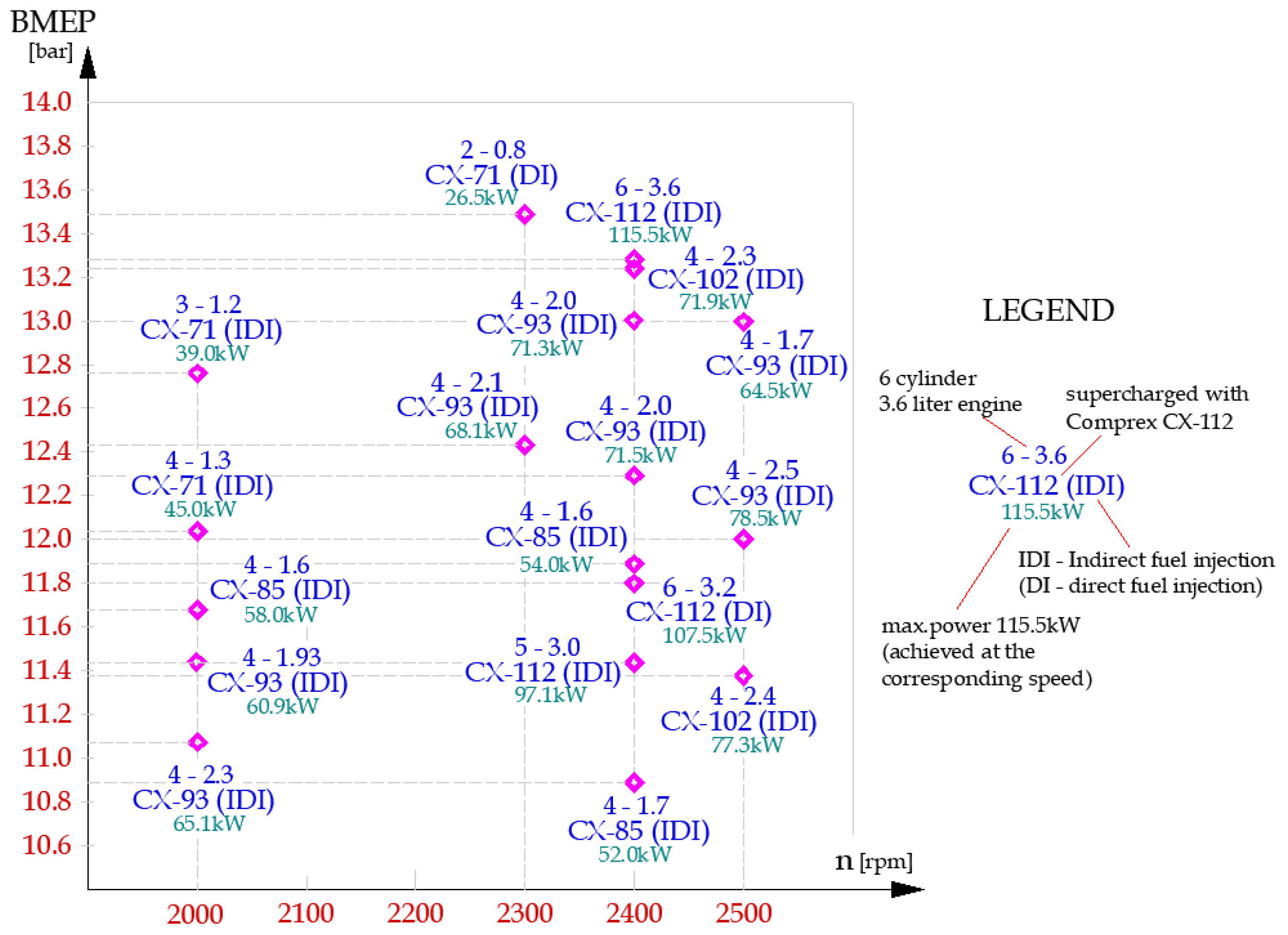
| Engine Displacement [L] | MEP Peak Value [bar] | Max. Power [kW] | Power/Displ. Ratio [kW/L] | Pressure Ratio | Reference (Year) |
|---|---|---|---|---|---|
| Diesel Heavy truck | |||||
| 5.9 | 11.4 | 130 | 22.1 | 2.10 | [17] (1960) |
| 11.1 | 13.7 | 220 | 19.8 | 2.35 | [19] (1970) |
| 10.8 | 14.4 | 210 | 19.4 | 2.35 | [37] (1984) |
| 2.7 | 63 | 23.3 | [88] (2010) | ||
| Diesel Passenger car | |||||
| 2.1 | 13.00 | 44.7 | 21.3 | 1.5 | [20] (1978) |
| 2.3 | 10.80 | 70 | 30.4 | [21,24] (1980) | |
| 0.8 | 13.45 | 26.6 | 33.2 | [23] (1980) | |
| 1.3 | 12.04 | 45 | 34.7 | ||
| 1.7 | 12.89 | 64.5 | 37.9 | ||
| 2.0 | 12.96 | 71.5 | 35.7 | ||
| 2.4 | 11.38 | 77 | 32.2 | ||
| 3.2 | 11.81 | 107.5 | 33.6 | ||
| 3.6 | 13.23 | 115.6 | 32.1 | ||
| 3.0 | 11.5 | 100 | 33.3 | 2.2 | [20,24] (1980s’) |
| 2.0 | 70 | 35.0 | 2.7 | [22] (1984) | |
| 2.0 | 14.5 | 61 | 30.5 | 2.2 | [34] (1990) |
| 1.4 | 82 | 58.5 | 2.5 | [90] (2013) | |
| Gasoline | |||||
| 0.36 | 40 | 111 | 2.4 | [39] (1998) | |
| 1.0 (Hyprex) | 25.0 | 100 | 100 | [40] (2006) | |
| Hydrogen | |||||
| 2.0 (Antrova Comprex) | 28.0 (simulation data) | [96] (2019) | |||
| Natural gas | |||||
| 3.0 (Antrova Comprex) | >25.0 | 120 | 40 | [95] (2021) | |
Publisher’s Note: MDPI stays neutral with regard to jurisdictional claims in published maps and institutional affiliations. |
© 2022 by the authors. Licensee MDPI, Basel, Switzerland. This article is an open access article distributed under the terms and conditions of the Creative Commons Attribution (CC BY) license (https://creativecommons.org/licenses/by/4.0/).
Share and Cite
Costiuc, I.; Chiru, A.; Costiuc, L. A Review of Engine’s Performance When Supercharging by a Pressure Wave Supercharger. Energies 2022, 15, 2721. https://doi.org/10.3390/en15082721
Costiuc I, Chiru A, Costiuc L. A Review of Engine’s Performance When Supercharging by a Pressure Wave Supercharger. Energies. 2022; 15(8):2721. https://doi.org/10.3390/en15082721
Chicago/Turabian StyleCostiuc, Iuliana, Anghel Chiru, and Liviu Costiuc. 2022. "A Review of Engine’s Performance When Supercharging by a Pressure Wave Supercharger" Energies 15, no. 8: 2721. https://doi.org/10.3390/en15082721
APA StyleCostiuc, I., Chiru, A., & Costiuc, L. (2022). A Review of Engine’s Performance When Supercharging by a Pressure Wave Supercharger. Energies, 15(8), 2721. https://doi.org/10.3390/en15082721