
Membrane and Electrochemical Based Technologies for the Decontamination of Exploitable Streams Produced by Thermochemical Processing of Contaminated Biomass


 , ,
, ,  ,
, 
Abstract
1. Introduction
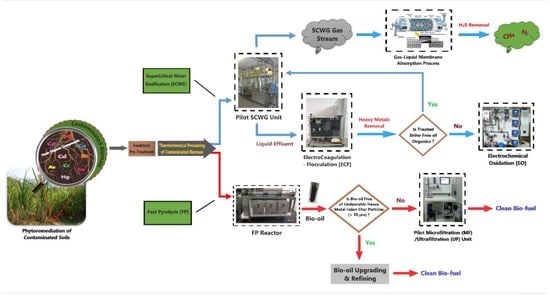
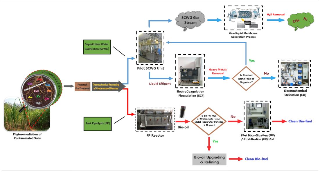
2. Thermochemical Processing of Contaminated Biomass
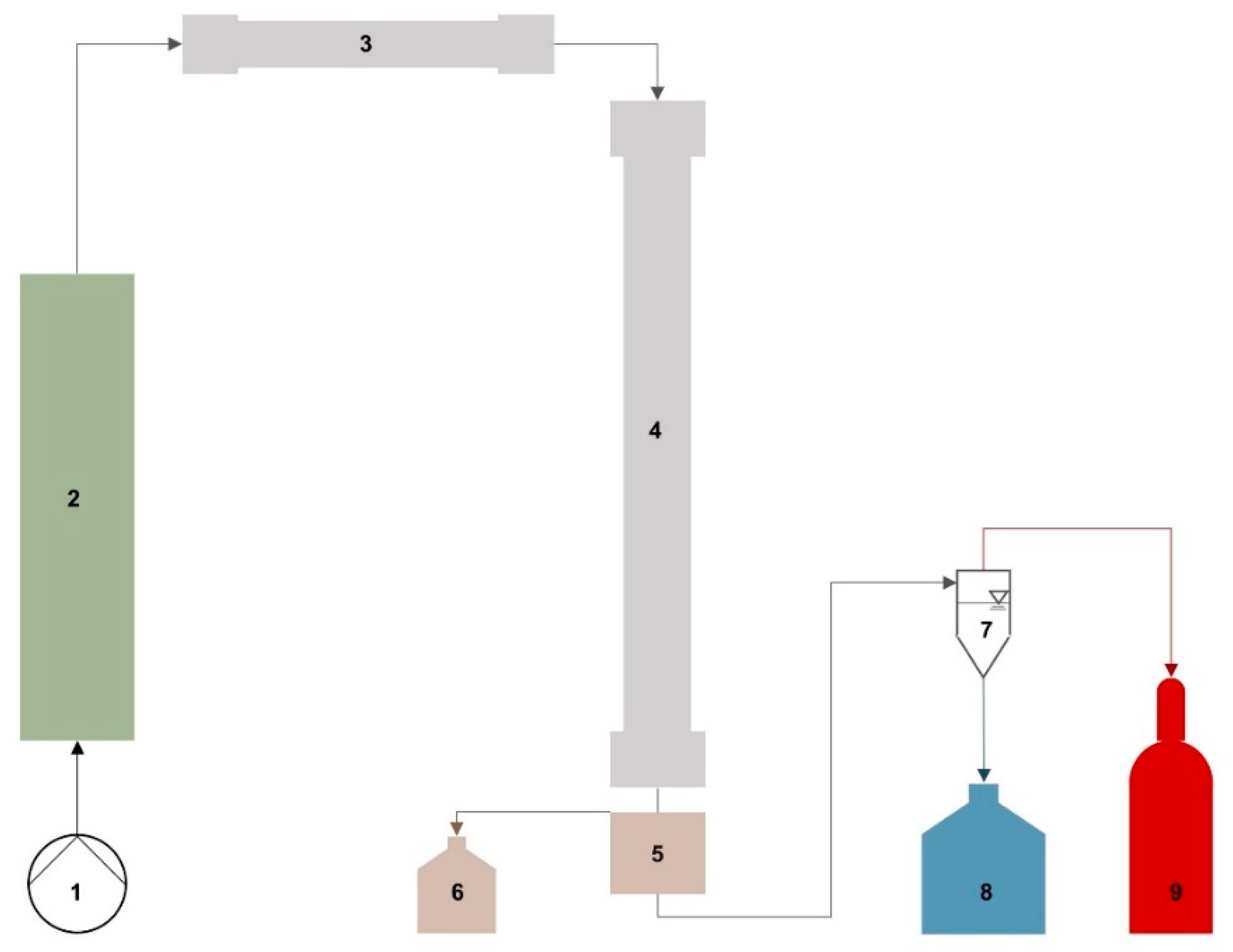
2.1. The SCWG Process and Its Products
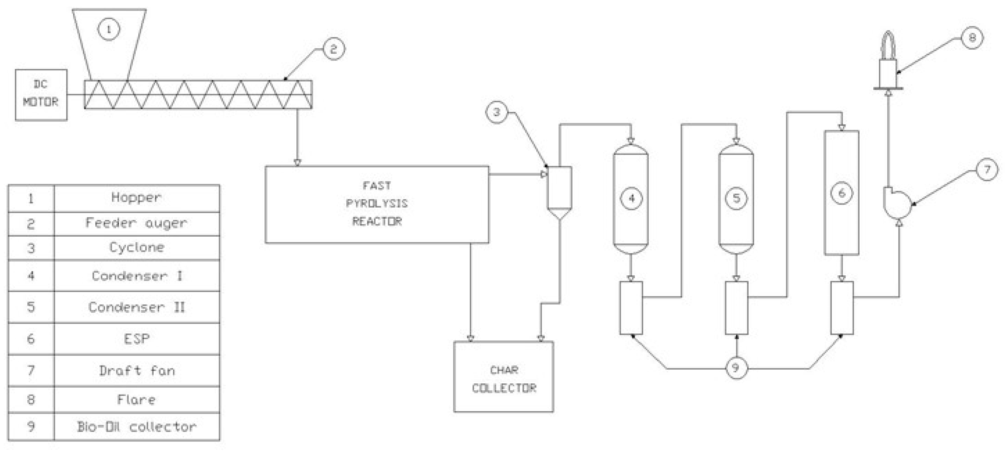
2.2. The FP Process and Its Products
3. Decontamination Technologies of Gaseous/Liquid Effluents
3.1. SCWG Gas Effluent Treatment
3.1.1. Methods for Sour Gas Purification
Chemical or Physical Absorption in Packed Columns
Adsorption
Cryogenic Distillation
Membranes
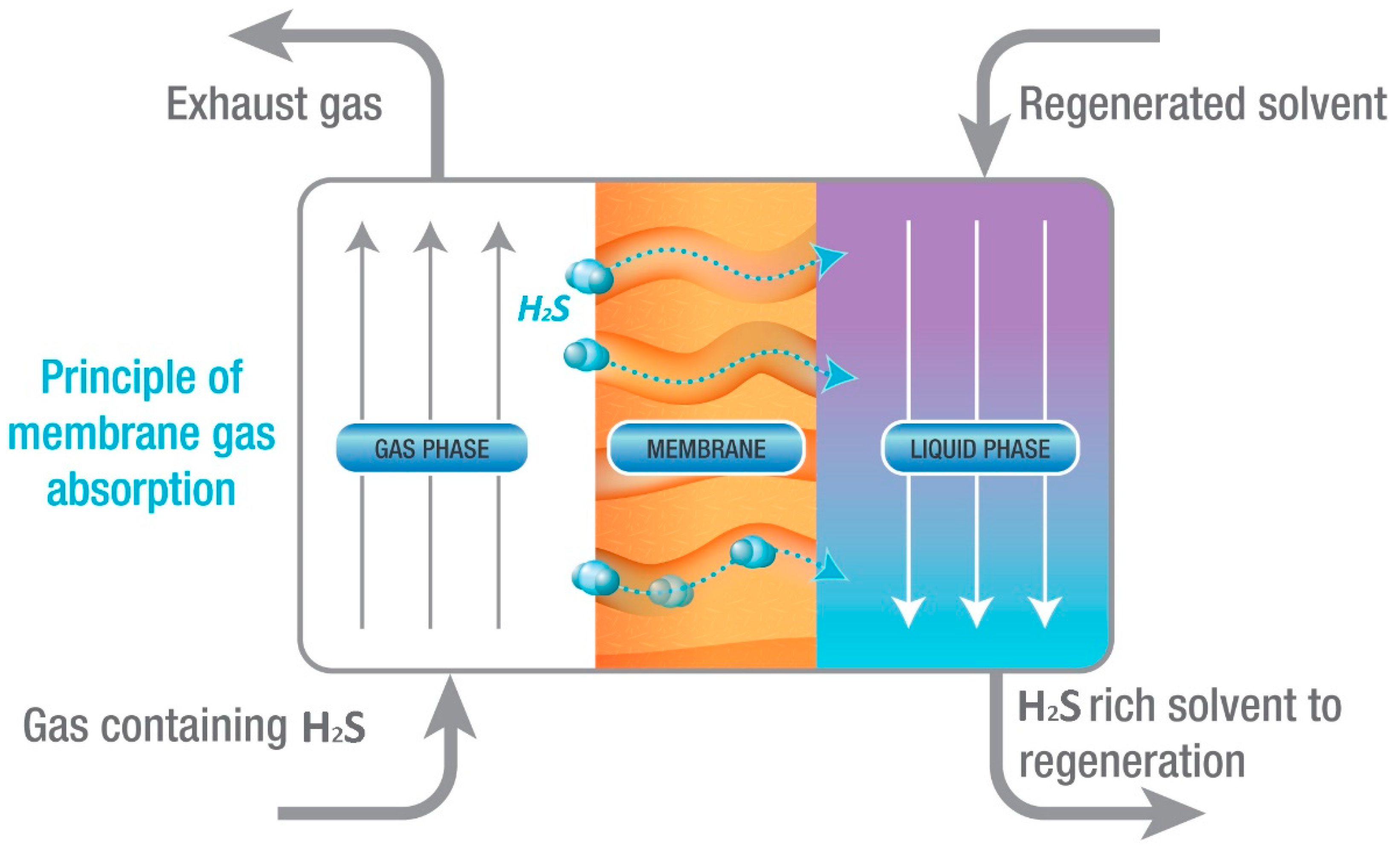
Membrane Gas Absorption (MGA)
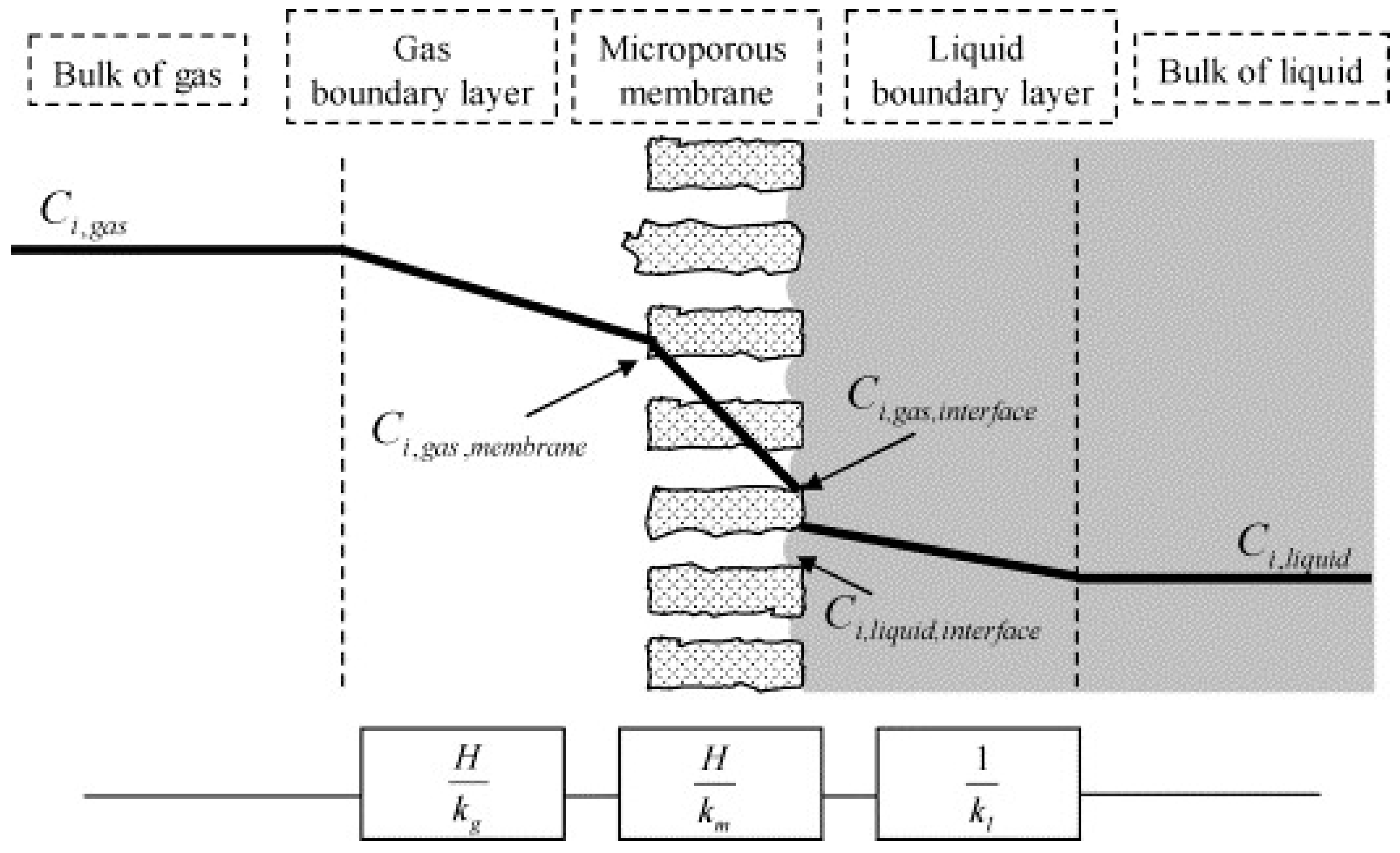
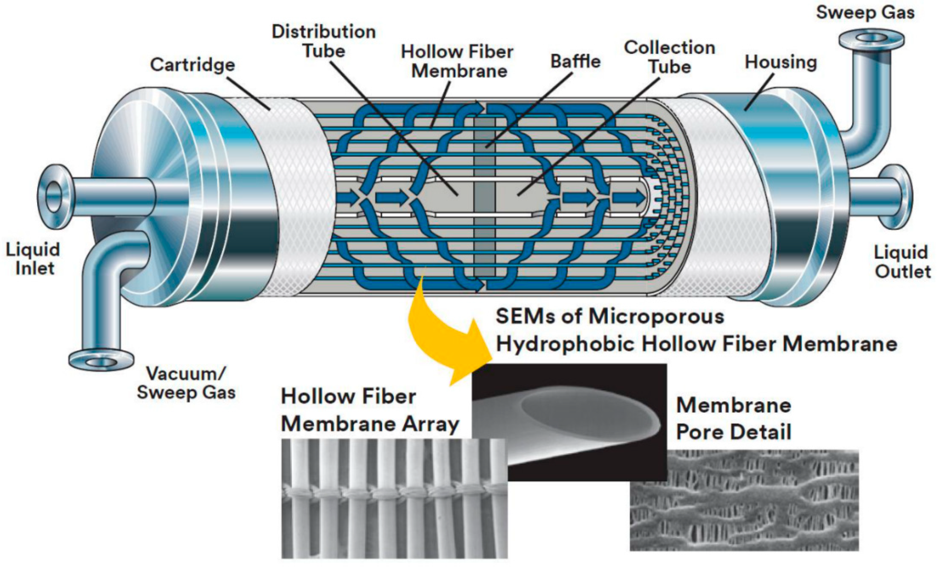
3.1.2. Detailed Description of Membrane Gas Absorption (MGA) Technology
Theoretical Background
Advantages and Disadvantages of the MGA Technology
- The contact area does not depend on gas and liquid flow rates as the two-fluid flows are independent. This is particularly important in cases where the required liquid/gas ratio needs to be very high or very low. In these cases, the conventional columns could have problems with flooding at high flow rates or unloading at low ones.
- There are no problems that typically come from the gas dispersion into the liquid phase, like weeping, foaming, entrainment, etc.
- Scale-up is more straightforward with membrane contactors as they typically scale linearly. Increased capacities can be achieved simply by adding more membrane modules to a system.
- Modular design also offers flexibility in the operating capacity of a plant.
- The performance of membrane contactors typically can be predicted more easily as the contact area is known and constant a priori.
- The efficiency of membrane contactors (in terms of Height of a Transfer Unit/HTU) is substantially higher, mainly due to their high specific surface area.
- Solvent holdup is typically very low; a feature particularly important when expensive solvents are considered.
- The membrane introduces an extra resistance to mass transfer between the two phases. However, in many cases, this resistance is small compared to the other encountered in the process, and measures (design + operational) can be taken to reduce its contribution further.
- Partial membrane wetting with time can potentially increase the mass transfer resistance of the process. Careful selection of membrane materials, solvents, and process conditions is needed to avoid this phenomenon.
- Membrane contactors are subject to shell side bypassing, especially at low flow rates, which reduces the efficiency of the system. Fortunately, several design improvements have been proposed to address this problem when scaling up to large-area membrane modules.
- Membranes are subject to fouling. Although this tends to be more of a problem in filtration applications and not in membrane contactors, it must be considered for specific cases.
- Membranes have a limited lifetime. Thus, the cost of periodic membrane replacement must be considered. However, the cost corresponding to membrane materials and shaping/assembly is by no means prohibitively high to not, at least in principle, allow such a strategy.
- The potting adhesive (e.g., epoxy) used in sealing the bundle of fibers may be vulnerable to attack by organic solvents, considering a long-term operation.
Membranes and Modules
Survey on Candidate Solvents
- Operating data for solvents typically used in conventional sour gas absorption processes
- Data on solvents compatibility with membrane materials
- Data related to solvents availability, cost, management, regeneration potential, etc.
- Wetting due to possible chemical reactions between the membranes and the solvent can change the hydrophobic characteristics of the system.
- Wetting due to physical interaction between the membrane pores and solvents (e.g., swelling) results in significant surface morphology changes.
- Wetting due to changes in membrane surface hydrophobicity by trace impurities in the solvent.
- Inorganic solvents such as H2O, NaOH, and K2CO3 have high surface tension and do not easily wet the common hydrophobic membranes. However, they are typically less efficient than the conventional amine ones.
- Amines are the most commonly employed solvents in hollow fiber membrane contactors and they have high absorption performance and regeneration potential. However, the surface tension of these solvents is typically lower compared with the inorganic ones and they tend to wet the common hydrophobic membranes more easily.
- Using MEA as an absorbent for long-term operations results in dramatic flux declines in all commercial hydrophobic membranes. Their surface morphologies, hydrophobicities, and chemical properties are greatly affected by amine attacks. DEA and MDEA tend to have milder effects on membranes performance.
Literature Survey on Sour Gas Treatment with MGA Technology
3.2. SCWG Liquid Effluent Treatment
3.2.1. State-of-the-Art of Saline Wastewater Decontamination
3.2.2. Decontamination of Brines by Electrocoagulation
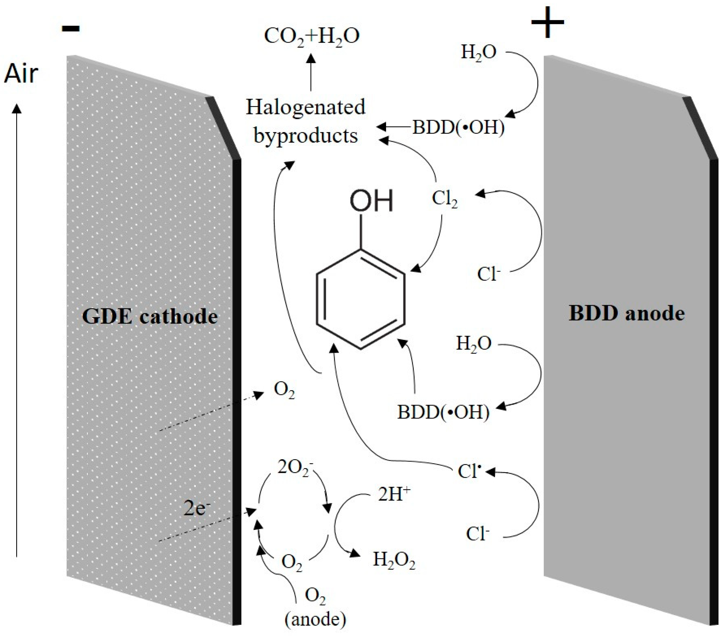
3.2.3. Organic Destruction in Brines by Electrochemical Oxidation
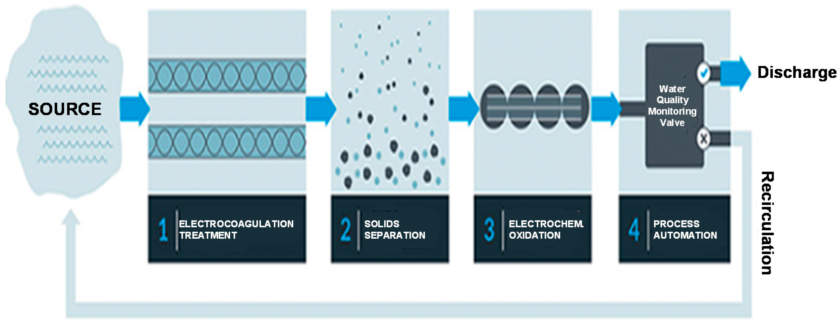
3.2.4. Treatment of SCWG Liquid Effluents by EC/EO
Electrode Materials
Operating Conditions
EC Solid By-Product (Sludge) Treatment and Reuse Options
3.3. FP Liquid Effluent Treatment
3.3.1. State-of-the-Art of Bio-Oil Decontamination
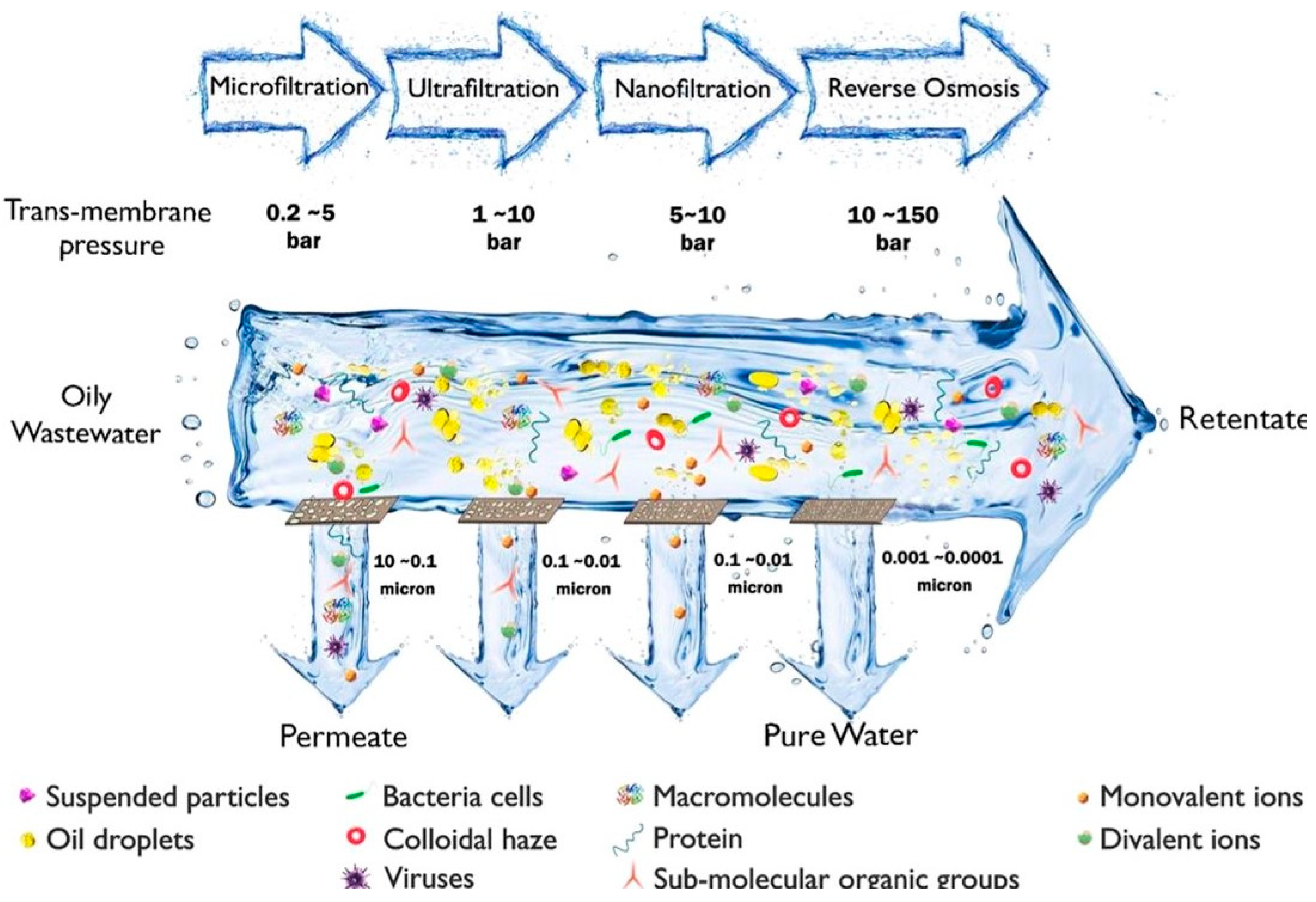
3.3.2. Treatment of FP Bio-Oil by Ceramic MF/UF
4. Conclusions and Future Recommendations
Author Contributions
Funding
Institutional Review Board Statement
Informed Consent Statement
Data Availability Statement
Conflicts of Interest
References
- Pérez, A.P.; Eugenio, N.R. Status of local soil contamination in Europe: Revision of the indicator. In Progress in the Management Contaminated Sites in Europe; Publications Office of the European Union: Luxembourg, 2018. [Google Scholar] [CrossRef]
- Panagos, P.; Hiederer, R.; Van Liedekerke, M.; Bampa, F. Estimating soil organic carbon in Europe based on data collected through an European network. Ecol. Indic. 2013, 24, 439–450. [Google Scholar] [CrossRef]
- Searchinger, T.; Waite, R.; Hanson, C.; Ranganathan, J. Creating a Sustainable Food Future; Worlds Resources Institute: Washington, DC, USA, 2018; pp. 1–96. [Google Scholar]
- Pandey, V.C.; Bajpai, O.; Singh, N. Energy crops in sustainable phytoremediation. Renew. Sustain. Energy Rev. 2019, 54, 58–73. [Google Scholar] [CrossRef]
- Contaminated Land Remediation through Energy Crops for Soil Improvement to Liquid Biofuel Strategies. Available online: https://www.ceresis.eu/ (accessed on 1 February 2022).
- Arun, J.; Gopinath, K.P.; SundarRajan, P.; Felix, V.; JoselynMonica, M.; Malolan, R. A conceptual review on microalgae biorefinery through thermochemical and biological pathways: Bio-Circular Approach on Carbon Capture and Wastewater Treatment. Bioresour. Technol. Rep. 2020, 11, 100477. [Google Scholar] [CrossRef]
- Lee, X.J.; Ong, H.C.; Gan, Y.Y.; Chen, W.-H.; Mahlia, T.M.I. State of art review on conventional and advanced pyrolysis of macroalgae and microalgae for biochar, bio-oil and bio-syngas production. Energy Convers. Manag. 2020, 210, 112707. [Google Scholar] [CrossRef]
- Gopirajan, P.V.; Gopinath, K.P.; Sivaranjani, G.; Arun, J. Optimization of hydrothermal liquefaction process through machine learning approach: Process Conditions and Oil Yield. Biomass. Convers. Biorefin. 2021, 1–10. [Google Scholar] [CrossRef]
- Kumar, M.; Oyedun, A.O.; Kumar, A. A review on the current status of various hydrothermal technologies on biomass feedstock. Renew. Sustain. Energy Rev. 2018, 81, 1742–1770. [Google Scholar] [CrossRef]
- Boukis, N.; Stoll, I. Gasification of Biomass in Supercritical Water, Challenges for the Process Design—Lessons Learned from the Operation Experience of the First Dedicated Pilot Plant. Processes 2021, 9, 455. [Google Scholar] [CrossRef]
- Schubert, M.; Regler, J.W.; Vogel, F. Continuous salt precipitation and separation from supercritical water. Part 1: Type 1 Salts. J. Supercrit. Fluids 2010, 52, 99–112. [Google Scholar] [CrossRef]
- Schubert, M.; Regler, J.W.; Vogel, F. Continuous salt precipitation and separation from supercritical water. Part 2. Type 2 salts and mixtures of two salts. J. Supercrit. Fluids 2010, 52, 113–124. [Google Scholar] [CrossRef]
- Boukis, N.; Hauer, E.; Herbig, S.; Sauer, J.; Vogel, F. Catalytic gasification of digestate sludge in supercritical water on the pilot plant scale. Biomass Conv. Bioref. 2017, 7, 415–424. [Google Scholar] [CrossRef]
- Reimer, J.; Peng, G.; Viereck, S.; De Boni, E.; Breinl, J.; Vogel, F. A novel salt separator for the supercritical water gasification of biomass. J. Supercrit. Fluids 2016, 117, 113–121. [Google Scholar] [CrossRef]
- Kruse, A.; Funke, A.; Titirici, M.-M. Hydrothermal conversion of biomass to fuels and energetic materials. Curr. Opin. Chem. Biol. 2013, 17, 515–521. [Google Scholar] [CrossRef] [PubMed]
- Huang, H.-J.; Yuan, X.-Z. The migration and transformation behaviors of heavy metals during the hydrothermal treatment of sewage sludge. Bioresour. Technol. 2016, 200, 991–998. [Google Scholar] [CrossRef] [PubMed]
- Li, J.; Chen, J.; Chen, S. Supercritical water treatment of heavy metal and arsenic metalloid-bioaccumulating-biomass. Ecotoxicol. Environ. Saf. 2018, 157, 102–110. [Google Scholar] [CrossRef]
- Su, W.; Liu, P.; Cai, C.; Ma, H.; Jiang, B.; Xing, Y.; Liang, Y.; Cai, L.; Xia, C.; Van Le, Q.; et al. Hydrogen production and heavy metal immobilization using hyperaccumulators in supercritical water gasification. J. Hazard. Mater. 2021, 402, 123541. [Google Scholar] [CrossRef] [PubMed]
- Giudicianni, P.; Gargiulo, V.; Grottola, C.M.; Alfè, M.; Ferreiro, A.I.; Mendes, M.A.A.; Fagnano, M.; Ragucci, R. Inherent Metal Elements in Biomass Pyrolysis: A Review. Energy Fuels 2021, 35, 5407–5478. [Google Scholar] [CrossRef]
- Gargiulo, V.; Ferreiro, A.I.; Giudicianni, P.; Tomaselli, S.; Costa, M.; Ragucci, R.; Alfe, M. Insights about the effect of composition, branching and molecular weight on the slow pyrolysis of xylose-based polysaccharides. J. Anal. Appl. Pyrolysis 2022, 161, 105369. [Google Scholar] [CrossRef]
- Branca, C.; Giudicianni, P.; Di Blasi, C. GC/MS Characterization of Liquids Generated from Low-Temperature Pyrolysis of Wood. Ind. Eng. Chem. Res. 2003, 42, 3190–3202. [Google Scholar] [CrossRef]
- Lievens, C.; Yperman, J.; Vangronsveld, J.; Carleer, R. Study of the potential valorisation of heavy metal contaminated biomass via phytoremediation by fast pyrolysis: Part I. Influence of temperature, biomass species and solid heat carrier on the behaviour of heavy metals. Fuel 2008, 87, 1894–1905. [Google Scholar] [CrossRef]
- Lievens, C.; Yperman, J.; Cornelissen, T.; Carleer, R. Study of the potential valorisation of heavy metal contaminated biomass via phytoremediation by fast pyrolysis: Part II: Characterisation of the Liquid and Gaseous Fraction as a Function of the Temperature. Fuel 2008, 87, 1906–1916. [Google Scholar] [CrossRef]
- Bridgwater, A.V.; Meier, D.; Radlein, D. An overview of fast pyrolysis of biomass. Org. Geochem. 1999, 30, 1479–1493. [Google Scholar] [CrossRef]
- Oasmaa, A.; van de Beld, B.; Saari, P.; Elliott, D.C.; Solantausta, Y. Norms, Standards, and Legislation for Fast Pyrolysis Bio-oils from Lignocellulosic Biomass. Energy Fuels 2015, 29, 2471–2484. [Google Scholar] [CrossRef]
- Hoekstra, E.; Hogendoorn, K.J.A.; Wang, X.; Westerhof, R.J.M.; Kersten, S.R.A.; van Swaaij, W.P.M.; Groeneveld, M.J. Fast Pyrolysis of Biomass in a Fluidized Bed Reactor: In Situ Filtering of the Vapors. Ind. Eng. Chem. Res. 2009, 48, 4744–4756. [Google Scholar] [CrossRef]
- NREL Report. Survey and Down-Selection of Acid Gas Removal Systems for the Thermochemical Conversion of Biomass to Ethanol with a Detailed Analysis of an MDEA System. 2011. Available online: http://www.osti.gov/bridge (accessed on 1 February 2022).
- Liang, C.Z.; Chung, T.-S.; Lai, J.-Y. A review of polymeric composite membranes for gas separation and energy production. Prog. Polym. Sci. 2019, 97, 101141. [Google Scholar] [CrossRef]
- Valappil, R.S.K.; Ghasem, N.; Al-Marzouqi, M. Current and future trends in polymer membrane-based gas separation technology: A Comprehensive Review. J. Ind. Eng. Chem. 2021, 98, 103–129. [Google Scholar] [CrossRef]
- George, G.; Bhoria, N.; AlHallaq, S.; Abdala, A.; Mittal, V. Polymer membranes for acid gas removal from natural gas. Sep. Purif. Technol. 2016, 158, 333–356. [Google Scholar] [CrossRef]
- Alqaheem, Y. A simulation study for the treatment of Kuwait sour gas by membranes. Heliyon 2021, 7, e05953. [Google Scholar] [CrossRef]
- Hafeez, S.; Safdar, T.; Pallari, E.; Manos, G.; Aristodemou, E.; Zhang, Z.; Al-Salem, S.M.; Constantinou, A. CO2 capture using membrane contactors: A Systematic Literature Review. Front. Chem. Sci. Eng. 2021, 15, 720–754. [Google Scholar] [CrossRef]
- Atchariyawut, S.; Feng, C.; Wang, R.; Jiraratananon, R.; Liang, D. Effect of membrane structure on mass-transfer in the membrane gas–liquid contacting process using microporous PVDF hollow fibers. J. Membr. Sci. 2006, 285, 272–281. [Google Scholar] [CrossRef]
- Bazhenov, S.D.; Lyubimova, E.S. Gas–liquid membrane contactors for carbon dioxide capture from gaseous streams. Pet. Chem. 2016, 56, 889–914. [Google Scholar] [CrossRef]
- Gabelman, A.; Hwang, S.-T. Hollow fiber membrane contactors. J. Membr. Sci. 1999, 159, 61–106. [Google Scholar] [CrossRef]
- Khaisri, S.; Demontigny, D.; Tontiwachwuthikul, P.; Jiraratananon, R. Comparing membrane resistance and absorption performance of three different membranes in a gas absorption membrane contactor. Sep. Purif. Technol. 2009, 65, 290–297. [Google Scholar] [CrossRef]
- MTM Liqui-CelTM Publications and Case Studies. Optimized Deaeration System for Paulaner Brewery. Available online: https://multimedia.3m.com/mws/media/1412652O/3m-liqui-cel-membrane-contactors-optimized-deaeration-system.pdf (accessed on 1 February 2022).
- Singh, P. Amine Based Solvent for CO2 Absorption: From Molecular Structure to Process. Ph.D. Thesis, University of Twente, Twente, The Netherlands, 2011. [Google Scholar] [CrossRef]
- Shah, M.S.; Tsapatsis, M.; Siepmann, J.I. Hydrogen Sulfide Capture: From Absorption in Polar Liquids to Oxide, Zeolite, and Metal–Organic Framework Adsorbents and Membranes. Chem. Rev. 2017, 117, 9755–9803. [Google Scholar] [CrossRef] [PubMed]
- Cui, Z.; Demontigny, D. Part 7: A Review of CO2 Capture Using Hollow Fiber Membrane Contactors. Carbon Manag. 2013, 4, 69–89. [Google Scholar] [CrossRef]
- Xu, Y.; Malde, C.; Wang, R. Correlating Physicochemical Properties of Commercial Membranes with CO2 Absorption Performance in Gas-Liquid Membrane Contactor. J. Membr. Sci. Res. 2020, 6, 30–39. [Google Scholar] [CrossRef]
- Kim, S.; Scholes, C.A.; Heath, D.E.; Kentish, S.E. Gas-liquid membrane contactors for carbon dioxide separation: A Review. Chem. Eng. J. 2021, 411, 128468. [Google Scholar] [CrossRef]
- CO2 Capture/Separation Technologies, CO2CRC. Available online: https://co2crc.com.au/wp-content/uploads/2020/08/membrane_gasadsorption.jpg (accessed on 1 February 2022).
- Bazhenov, S.D.; Bildyukevich, A.V.; Volkov, A.V. Gas-Liquid Hollow Fiber Membrane Contactors for Different Applications. Fibers 2018, 6, 76. [Google Scholar] [CrossRef]
- Hedayat, M.; Soltanieh, M.; Mousavi, S.A. Simultaneous separation of H2S and CO2 from natural gas by hollow fiber membrane contactor using mixture of alkanolamines. J. Membr. Sci. 2011, 377, 191–197. [Google Scholar] [CrossRef]
- Faiz, R.; Li, K.; Al-Marzouqi, M. H2S absorption at high pressure using hollow fibre membrane contactors. Chem. Eng. Process. Process Intensif. 2014, 83, 33–42. [Google Scholar] [CrossRef]
- Al-Marzouqi, M.H.; Marzouk, S.; Abdullatif, N. High pressure removal of acid gases using hollow fiber membrane contactors: Further characterization and long-term operational stability. J. Nat. Gas Sci. Eng. 2017, 37, 192–198. [Google Scholar] [CrossRef]
- Marzouk, S.A.; Al-Marzouqi, M.; Teramoto, M.; Abdullatif, N.; Ismail, Z.M. Simultaneous removal of CO2 and H2S from pressurized CO2–H2S–CH4 gas mixture using hollow fiber membrane contactors. Sep. Purif. Technol. 2012, 86, 88–97. [Google Scholar] [CrossRef]
- Rongwong, W.; Boributh, S.; Assabumrungrat, S.; Laosiripojana, N.; Jiraratananon, R. Simultaneous absorption of CO2 and H2S from biogas by capillary membrane contactor. J. Membr. Sci. 2012, 392-393, 38–47. [Google Scholar] [CrossRef]
- Jin, P.; Huang, C.; Shen, Y.; Zhan, X.; Hu, X.; Wang, L.; Wang, L. Simultaneous Separation of H2S and CO2 from Biogas by Gas–Liquid Membrane Contactor Using Single and Mixed Absorbents. Energy Fuels 2017, 31, 11117–11126. [Google Scholar] [CrossRef]
- Tilahun, E.; Bayrakdar, A.; Sahinkaya, E.; Çalli, B. Performance of polydimethylsiloxane membrane contactor process for selective hydrogen sulfide removal from biogas. Waste Manag. 2017, 61, 250–257. [Google Scholar] [CrossRef]
- Tilahun, E.; Sahinkaya, E.; Çalli, B. A hybrid membrane gas absorption and bio-oxidation process for the removal of hydrogen sulfide from biogas. Int. Biodeterior. Biodegrad. 2018, 127, 69–76. [Google Scholar] [CrossRef]
- Wang, D.; Teo, W.; Li, K. Removal of H2S to ultra-low concentrations using an asymmetric hollow fibre membrane module. Sep. Purif. Technol. 2002, 27, 33–40. [Google Scholar] [CrossRef]
- Boucif, N.; Favre, E.; Roizard, D.; Belloul, M. Hollow fiber membrane contactor for hydrogen sulfide odor control. AIChE J. 2008, 54, 122–131. [Google Scholar] [CrossRef]
- Esquiroz-Molina, A.; Georgaki, S.; Stuetz, R.; Jefferson, B.; McAdam, E. Influence of pH on gas phase controlled mass transfer in a membrane contactor for hydrogen sulphide absorption. J. Membr. Sci. 2013, 427, 276–282. [Google Scholar] [CrossRef]
- Petukhov, D.; Komkova, M.; Eliseev, A.; Poyarkov, A. Nanoporous polypropylene membrane contactors for CO2 and H2S capture using alkali absorbents. Chem. Eng. Res. Des. 2022, 177, 448–460. [Google Scholar] [CrossRef]
- Mirfendereski, M. Investigation of H2S and CO2 Removal from Gas Streams Using Hollow Fiber Membrane Gas–liquid Contactors. Chem. Biochem. Eng. Q. 2017, 31, 139–144. [Google Scholar] [CrossRef]
- Mirfendereski, S.M.; Niazi, Z.; Mohammadi, T. Selective Removal of H2 S from Gas Streams with High CO2 Concentration Using Hollow-Fiber Membrane Contractors. Chem. Eng. Technol. 2019, 42, 196–208. [Google Scholar] [CrossRef]
- Gagnon, G.A.; Krkosek, W.; Anderson, L.; McBean, E.; Mohseni, M.; Bazri, M.; Mauro, I. Impacts of hydraulic fracturing on water quality: A Review of Literature, Regulatory Frameworks and an Analysis of Information Gaps. Environ. Rev. 2016, 24, 122–131. [Google Scholar] [CrossRef]
- Lefebvre, O.; Moletta, R. Treatment of organic pollution in industrial saline wastewater: A Literature Review. Water Res. 2006, 40, 3671–3682. [Google Scholar] [CrossRef] [PubMed]
- Ferrer-Polonio, E.; Carbonell-Alcaina, C.; Mendoza-Roca, J.; Iborra-Clar, A.; Álvarez-Blanco, S.; Bes-Piá, A.; Pastor-Alcañiz, L. Brine recovery from hypersaline wastewaters from table olive processing by combination of biological treatment and membrane technologies. J. Clean. Prod. 2017, 142, 1377–1386. [Google Scholar] [CrossRef]
- Jones, E.; Qadir, M.; van Vliet, M.T.; Smakhtin, V.; Kang, S.-M. The state of desalination and brine production: A Global Outlook. Sci. Total Environ. 2018, 657, 1343–1356. [Google Scholar] [CrossRef]
- Roberts, D.A.; Johnston, E.; Knott, N.A. Impacts of desalination plant discharges on the marine environment: A Critical Review of published studies. Water Res. 2010, 44, 5117–5128. [Google Scholar] [CrossRef]
- Rosenblum, J.; Nelson, A.W.; Ruyle, B.; Schultz, M.; Ryan, J.N.; Linden, K.G. Temporal characterization of flowback and produced water quality from a hydraulically fractured oil and gas well. Sci. Total Environ. 2017, 596–597, 369–377. [Google Scholar] [CrossRef]
- Orem, W.; Varonka, M.; Crosby, L.; Haase, K.; Loftin, K.; Hladik, M.; Akob, D.M.; Tatu, C.; Mumford, A.; Jaeschke, J.; et al. Organic geochemistry and toxicology of a stream impacted by unconventional oil and gas wastewater disposal operations. Appl. Geochem. 2017, 80, 155–167. [Google Scholar] [CrossRef]
- Mavukkandy, M.O.; Chabib, C.M.; Mustafa, I.; Al Ghaferi, A.; AlMarzooqi, F. Brine management in desalination industry: From waste to resources generation. Desalination 2019, 472, 114187. [Google Scholar] [CrossRef]
- Khosravi, J.; Alamdari, A. Copper removal from oil-field brine by coprecipitation. J. Hazard. Mater. 2009, 166, 695–700. [Google Scholar] [CrossRef]
- Fu, F.; Wang, Q. Removal of heavy metal ions from wastewaters: A review. J. Environ. Manag. 2011, 92, 407–418. [Google Scholar] [CrossRef] [PubMed]
- Fazlollahi, F.; Zarei, M.M.; Habashi, M.S.; Baxter, L.L. Method for Removal of Mercury from Oil Field Brine with Calcium Carbonate Co-precipitation. In Characterization of Minerals, Metals, and Materials; Wiley: Hoboken, NJ, USA, 2014; pp. 131–138. [Google Scholar] [CrossRef]
- Habashi, M.S.; Zarei, M.M.; Moreno-Atanasio, R. Experimental Study of Heavy Metal Ions Removal from Oil Field Brine. In Proceedings of the SPE Annual Caspian Technical Conference & Exhibition, Baku, Azerbaijan, 4–6 November 2015; pp. 1–10. [Google Scholar] [CrossRef]
- Katal, R.; Ying Shen, T.; Jafari, I.; Masudy-Panah, S.; Farahani, M.H.D.A. An Overview on the Treatment and Management of the Desalination Brine Solution. In Desalination-Challenges and Opportunities; Farahani, M.H.D.A., Vahid Vatanpour, V., Taheri, A.H., Eds.; Intech Open: London, UK, 2020. [Google Scholar] [CrossRef]
- Sahu, P. A comprehensive review of saline effluent disposal and treatment: Conventional Practices, Emerging Technologies, and Future Potential. J. Water Reuse Desalination 2021, 11, 33–65. [Google Scholar] [CrossRef]
- Chen, G.; Gras, S.; Kentish, S. Eutectic freeze crystallization of saline dairy effluent. Desalination 2020, 480, 114349. [Google Scholar] [CrossRef]
- Giwa, A.; Dufour, V.; AlMarzooqi, F.; Al Kaabi, M.; Hasan, S.W. Brine management methods: Recent Innovations and Current Status. Desalination 2017, 407, 1–23. [Google Scholar] [CrossRef]
- Mansour, S.; Arafat, H.A.; Hasan, S.W. Brine Management in Desalination Plants. In Desalination Sustainability; Elsevier: Amsterdam, The Netherlands, 2017; pp. 207–236. [Google Scholar] [CrossRef]
- Shaffer, D.L.; Chavez, L.H.A.; Ben-Sasson, M.; Castrillón, S.R.-V.; Yip, N.Y.; Elimelech, M. Desalination and Reuse of High-Salinity Shale Gas Produced Water: Drivers, Technologies, and Future Directions. Environ. Sci. Technol. 2013, 47, 9569–9583. [Google Scholar] [CrossRef]
- Alzahrani, S.; Mohammad, A.W. Challenges and Trends in Membrane Technology Implementation for Produced Water Treatment: A Review. J. Water Process Eng. 2014, 4, 107–133. [Google Scholar] [CrossRef]
- Silva, T.L.; Morales-Torres, S.; Castro-Silva, S.; Figueiredo, J.; Silva, A.M. An overview on exploration and environmental impact of unconventional gas sources and treatment options for produced water. J. Environ. Manag. 2017, 200, 511–529. [Google Scholar] [CrossRef]
- Islam, S.; Sultana, S.; McCutcheon, J.R.; Rahaman, S. Treatment of fracking wastewaters via forward osmosis: Evaluation of Suitable Organic Draw Solutions. Desalination 2019, 452, 149–158. [Google Scholar] [CrossRef]
- Chen, G.; Tan, L.; Xie, M.; Liu, Y.; Lin, Y.; Tan, W.; Huang, M. Direct contact membrane distillation of refining waste stream from precious metal recovery: Chemistry of Silica and Chromium (III) in Membrane Scaling. J. Membr. Sci. 2020, 598, 117803. [Google Scholar] [CrossRef]
- Khraisheh, M.; AlMomani, F.; Al-Ghouti, M. Electrospun Al2O3 hydrophobic functionalized membranes for heavy metal recovery using direct contact membrane distillation. Int. J. Energy Res. 2021, 45, 8151–8167. [Google Scholar] [CrossRef]
- Attia, H.; Alexander, S.; Wright, C.J.; Hilal, N. Superhydrophobic electrospun membrane for heavy metals removal by air gap membrane distillation (AGMD). Desalination 2017, 420, 318–329. [Google Scholar] [CrossRef]
- Moradi, R.; Monfared, S.M.; Amini, Y.; Dastbaz, A. Vacuum enhanced membrane distillation for trace contaminant removal of heavy metals from water by electrospun PVDF/TiO2 hybrid membranes. Korean J. Chem. Eng. 2016, 33, 2160–2168. [Google Scholar] [CrossRef]
- Panagopoulos, A.; Haralambous, K.-J.; Loizidou, M. Desalination brine disposal methods and treatment technologies—A review. Sci. Total Environ. 2019, 693, 133545. [Google Scholar] [CrossRef] [PubMed]
- Pramanik, B.K.; Shu, L.; Jegatheesan, V. A review of the management and treatment of brine solutions. Environ. Sci. Water Res. Technol. 2017, 3, 625–658. [Google Scholar] [CrossRef]
- Castillo-Carvajal, L.C.; Sanz-Martín, J.L.; Barragán-Huerta, B.E. Biodegradation of organic pollutants in saline wastewater by halophilic microorganisms: A Review. Environ. Sci. Pollut. Res. Int. 2014, 21, 9578–9588. [Google Scholar] [CrossRef]
- Park, K.-Y.; Choi, S.-Y.; Lee, S.-H.; Kweon, J.-H.; Song, J.-H. Comparison of formation of disinfection by-products by chlorination and ozonation of wastewater effluents and their toxicity to Daphnia magna. Environ. Pollut. 2016, 215, 314–321. [Google Scholar] [CrossRef]
- Konggidinata, M.I.; Chao, B.; Lian, Q.; Subramaniam, R.; Zappi, M.; Gang, D.D. Equilibrium, kinetic and thermodynamic studies for adsorption of BTEX onto Ordered Mesoporous Carbon (OMC). J. Hazard. Mater. 2017, 336, 249–259. [Google Scholar] [CrossRef]
- Jiang, N.; Shang, R.; Heijman, S.G.J.; Rietveld, L.C. High-silica zeolites for adsorption of organic micro-pollutants in water treatment: A Review. Water Res. 2018, 144, 145–161. [Google Scholar] [CrossRef]
- Millar, G.; Couperthwaite, S.; Moodliar, C.D. Strategies for the management and treatment of coal seam gas associated water. Renew. Sustain. Energy Rev. 2016, 57, 669–691. [Google Scholar] [CrossRef]
- Lekhlif, B.; Oudrhiri, L.; Zidane, F.; Drogui, P.; Blais, J.F. Study of the electrocoagulation of electroplating industry wastewaters charged by nickel (II) and chromium (VI). J. Mater. Environ. Sci. 2014, 5, 111–120. [Google Scholar]
- Naje, A.S.; Chelliapan, S.; Zakaria, Z.; Ajeel, M.A.; Alaba, P.A. A review of electrocoagulation technology for the treatment of textile wastewater. Rev. Chem. Eng. 2017, 33, 263–292. [Google Scholar] [CrossRef]
- Chen, Y.; Baygents, J.C.; Farrell, J. Evaluating electrocoagulation and chemical coagulation for removing dissolved silica from high efficiency reverse osmosis (HERO) concentrate solutions. J. Water Process Eng. 2017, 16, 50–55. [Google Scholar] [CrossRef]
- Ashraf, S.N.; Rajapakse, J.; Dawes, L.A.; Millar, G.J. Electrocoagulation for the purification of highly concentrated brine produced from reverse osmosis desalination of coal seam gas associated water. J. Water Process Eng. 2019, 28, 300–310. [Google Scholar] [CrossRef]
- Berkani, I.; Belkacem, M.; Trari, M.; Lapicque, F.; Bensadok, K. Assessment of electrocoagulation based on nitrate removal, for treating and recycling the Saharan groundwater desalination reverse osmosis concentrate for a sustainable management of Albien resource. J. Environ. Chem. Eng. 2019, 7, 102951. [Google Scholar] [CrossRef]
- Lalia, B.S.; Hashaikeh, R. Electrochemical precipitation to reduce waste brine salinity. Desalination 2021, 498, 114796. [Google Scholar] [CrossRef]
- Mohammad, A.F.; Al-Marzouqi, A.H.; El-Naas, M.H.; Van der Bruggen, B.; Al-Marzouqi, M.H. A New Process for the Recovery of Ammonia from Ammoniated High-Salinity Brine. Sustainability 2021, 13, 10014. [Google Scholar] [CrossRef]
- Sardari, K.; Fyfe, P.; Lincicome, D.; Wickramasinghe, S.R. Combined electrocoagulation and membrane distillation for treating high salinity produced waters. J. Membr. Sci. 2018, 564, 82–96. [Google Scholar] [CrossRef]
- Azerrad, S.P.; Isaacs, M.; Dosoretz, C.G. Integrated treatment of reverse osmosis brines coupling electrocoagulation with advanced oxidation processes. Chem. Eng. J. 2018, 356, 771–780. [Google Scholar] [CrossRef]
- Sirés, I.; Brillas, E.; Oturan, M.A.; Rodrigo, M.A.; Panizza, M. Electrochemical Advanced Oxidation Processes: Today and Tomorrow. A Review. Environ. Sci. Pollut. Res. 2014, 21, 8336–8367. [Google Scholar] [CrossRef]
- Radjenovic, J.; Sedlak, D.L. Challenges and Opportunities for Electrochemical Processes as Next-Generation Technologies for the Treatment of Contaminated Water. Environ. Sci. Technol. 2015, 49, 11292–11302. [Google Scholar] [CrossRef]
- Martínez-Huitle, C.A.; Rodrigo, M.A.; Sirés, I.; Scialdone, O. Single and Coupled Electrochemical Processes and Reactors for the Abatement of Organic Water Pollutants: A Critical Review. Chem. Rev. 2015, 115, 13362–13407. [Google Scholar] [CrossRef] [PubMed]
- Tawabini, B.; Plakas, K.; Fraim, M.; Safi, E.; Oyehan, T.; Karabelas, A. Assessing the efficiency of a pilot-scale GDE/BDD electrochemical system in removing phenol from high salinity waters. Chemosphere 2020, 239, 124714. [Google Scholar] [CrossRef] [PubMed]
- Feng, L.; van Hullebusch, E.D.; Rodrigo, M.A.; Esposito, G.; Oturan, M.A. Removal of residual anti-inflammatory and analgesic pharmaceuticals from aqueous systems by electrochemical advanced oxidation processes. A review. Chem. Eng. J. 2013, 228, 944–964. [Google Scholar] [CrossRef]
- Chaplin, B.P. Critical review of electrochemical advanced oxidation processes for water treatment applications. Environ. Sci. Process. Impacts 2014, 16, 1182–1203. [Google Scholar] [CrossRef] [PubMed]
- Moreira, F.C.; Boaventura, R.A.R.; Brillas, E.; Vilar, V.J.P. Electrochemical advanced oxidation processes: A Review on their Application to Synthetic and Real Wastewaters. Appl. Catal. B Environ. 2017, 202, 217–261. [Google Scholar] [CrossRef]
- Brillas, E.; Garcia-Segura, S. Benchmarking recent advances and innovative technology approaches of Fenton, photo-Fenton, electro-Fenton, and related processes: A Review on the Relevance of Phenol as Model Molecule. Sep. Purif. Technol. 2020, 237, 116337. [Google Scholar] [CrossRef]
- Garcia-Segura, S.; Ocon, J.D.; Chong, M.N. Electrochemical oxidation remediation of real wastewater effluents—A Review. Process. Saf. Environ. Prot. 2018, 113, 48–67. [Google Scholar] [CrossRef]
- Mostafa, E.; Reinsberg, P.; Garcia-Segura, S.; Baltruschat, H. Chlorine species evolution during electrochlorination on boron-doped diamond anodes: In-situ Electrogeneration of Cl2, Cl2O and ClO2. Electrochim. Acta 2018, 281, 831–840. [Google Scholar] [CrossRef]
- Kapałka, A.; Fóti, G.; Comninellis, C. Kinetic Modelling of the Electrochemical Mineralization of Organic Pollutants for Wastewater Treatment. J. Appl. Electrochem. 2008, 38, 7–16. [Google Scholar] [CrossRef]
- Labiadh, L.; Barbucci, A.; Carpanese, M.P.; Gadri, A.; Ammar, S.; Panizza, M. Comparative depollution of Methyl Orange aqueous solutions by electrochemical incineration using TiRuSnO2, BDD and PbO2 as high oxidation power anodes. J. Electroanal. Chem. 2016, 766, 94–99. [Google Scholar] [CrossRef]
- Moussa, D.T.; El-Naas, M.H.; Nasser, M.; Al-Marri, M.J. A comprehensive review of electrocoagulation for water treatment: Potentials and challenges. J. Environ. Manag. 2017, 186, 24–41. [Google Scholar] [CrossRef] [PubMed]
- Vepsäläinen, M. ‘Electrocoagulation in the Treatment of Industrial Waters and Wastewaters’. Espoo 2012VTT Science, 19. 2012. Available online: https://www.vttresearch.com/sites/default/files/pdf/science/2012/S19.pdf (accessed on 1 February 2022).
- Rabaaoui, N.; Allagui, M.S. Anodic oxidation of salicylic acid on BDD electrode: Variable Effects and Mechanisms of Degradation. J. Hazard. Mater. 2012, 243, 187–192. [Google Scholar] [CrossRef] [PubMed]
- Pacheco, M.J.; Santos, V.; Ciríaco, L.; Lopes, A. Electrochemical degradation of aromatic amines on BDD electrodes. J. Hazard. Mater. 2011, 186, 1033–1041. [Google Scholar] [CrossRef] [PubMed]
- Safari, S.; Aghdam, M.A.; Kariminia, H. Electrocoagulation for COD and diesel removal from oily wastewater. Int. J. Environ. Sci. Technol. 2016, 13, 231–242. [Google Scholar] [CrossRef]
- Menkiti, M.C.; Onyechi, C.A.; Onukwuli, O.D. Evaluation of perikinetics compliance for the coag-flocculation of brewery effluent by Brachystegia eurycoma seed extract. Int. J. Multidiscip. Sci. Eng. 2011, 2, 77–83. [Google Scholar]
- Nwabanne, J.T.; Obi, C.C. Abattoir wastewater treatment by electrocoagulation using iron electrodes. Der Chem. Sin. 2017, 8, 254–260. [Google Scholar]
- Saad, M.E.K.; Rabaaoui, N.; Elaloui, E.; Moussaoui, Y. Mineralization of p-methylphenol in aqueous medium by anodic oxidation with a boron-doped diamond electrode. Sep. Purif. Technol. 2016, 171, 157–163. [Google Scholar] [CrossRef]
- Ghalwa, N.M.; Musabeh, A.Z.; Farhat, N.B. Performance Efficiency of Electrocoagulation Adsorption Process of Oxyfluorfen Herbicide from Aqueous Solutions Using Different Anodes. J. Environ. Anal. Toxicol. 2017, 7, 100448. [Google Scholar] [CrossRef]
- Jing, G.; Ren, S.; Gao, Y.; Sun, W.; Gao, Z. Electrocoagulation: A Promising Method to Treat and Reuse Mineral Processing Wastewater with High COD. Water 2020, 12, 595. [Google Scholar] [CrossRef]
- Khandegar, V.; Saroha, A.K. Electrochemical Treatment of Textile Effluent Containing Acid Red 131 Dye. J. Hazard. Toxic Radioact. Waste 2014, 18, 38–44. [Google Scholar] [CrossRef]
- Hasson, D.; Lumelsky, V.; Greenberg, G.; Pinhas, Y.; Semiat, R. Development of the electrochemical scale removal technique for desalination applications. Desalination 2008, 230, 329–342. [Google Scholar] [CrossRef]
- Secula, M.S.; Zaleschi, L.; Stan, C.S.; Mămăligă, I. Effects of electric current type and electrode configuration on the removal of Indigo Carmine from aqueous solutions by electrocoagulation in a batch reactor. Desalination Water Treat. 2014, 52, 6135–6144. [Google Scholar] [CrossRef]
- Dalvand, A.; Gholami, M.; Joneidi, A.; Mahmoodi, N.M. Dye Removal, Energy Consumption and Operating Cost of Electrocoagulation of Textile Wastewater as a Clean Process. Clean Soil Air Water 2011, 39, 665–672. [Google Scholar] [CrossRef]
- Cañizares, P.; Louhichi, B.; Gadri, A.; Nasr, B.; Paz, R.; Rodrigo, M.A.; Saez, C. Electrochemical treatment of the pollutants generated in an ink-manufacturing process. J. Hazard. Mater. 2007, 146, 552–557. [Google Scholar] [CrossRef]
- Xu, L.J.; Sheldon, B.W.; Larick, D.K.; Carawan, R.E. Recovery and utilization of useful by-products from egg processing wastewater by electrocoagulation. Poult. Sci. 2002, 81, 785–792. [Google Scholar] [CrossRef]
- Kushwaha, J.P.; Chandra Srivastava, V.; Mall, I.D. Studies on electrochemical treatment of dairy wastewater using aluminum electrode. AIChE J. 2010, 57, 2589–2598. [Google Scholar] [CrossRef]
- Kumar, M.; Ponselvan, F.I.; Malviya, J.R.; Srivastava, V.C.; Mall, I.D. Treatment of bio-digester effluent by electrocoagulation using iron electrodes. J. Hazard. Mater. 2009, 165, 345–352. [Google Scholar] [CrossRef]
- Linares-Hernández, I.; Barrera-Díaz, C.; Roa-Morales, G.; Bilyeu, B.; Ureña-Núñez, F. Influence of the anodic material on electrocoagulation performance. Chem. Eng. J. 2009, 148, 97–105. [Google Scholar] [CrossRef]
- Maggay, I.V.; Chang, Y.; Venault, A.; Dizon, G.V.; Wu, C.-J. Functionalized porous filtration media for gravity-driven filtration: Reviewing a New Emerging Approach for Oil and Water Emulsions Separation. Sep. Purif. Technol. 2021, 259, 117983. [Google Scholar] [CrossRef]
- Saththasivam, J.; Loganathan, K.; Sarp, S. An overview of oil–water separation using gas flotation systems. Chemosphere 2016, 144, 671–680. [Google Scholar] [CrossRef]
- Wang, C.; Alpatova, A.; McPhedran, K.N.; Gamal El-Din, M. Coagulation/flocculation process with polyaluminum chloride for the remediation of oil sands process-affected water. Performance and mechanism study. J. Εnviron. Manag. 2015, 160, 254–262. [Google Scholar] [CrossRef] [PubMed]
- Igunnu, E.T.; Chen, G.Z. Produced water treatment technologies. Int. J. Low-Carbon Technol. 2014, 9, 157–177. [Google Scholar] [CrossRef]
- Cheryan, M.; Rajagopalan, N. Membrane processing of oily streams. Wastewater treatment and waste reduction. J. Membr. Sci. 1998, 151, 13–28. [Google Scholar] [CrossRef]
- Munirasu, S.; Haija, M.A.; Banat, F. Use of membrane technology for oil field and refinery produced water treatment—A review. Process Saf. Environ. Prot. 2016, 100, 183–202. [Google Scholar] [CrossRef]
- Behroozi, A.H.; Ataabadi, M.R. Improvement in microfiltration process of oily wastewater: A comprehensive review over two decades. J. Environ. Chem. Eng. 2021, 9, 104981. [Google Scholar] [CrossRef]
- Javaid, A.; Ryan, T.; Berg, G.; Pan, X.; Vispute, T.; Bhatia, S.R.; Huber, G.; Ford, D.M. Removal of char particles from fast pyrolysis bio-oil by microfiltration. J. Membr. Sci. 2010, 363, 120–127. [Google Scholar] [CrossRef]
- Pinheiro, A.; Hudebine, D.; Dupassieux, N.; Charon, N.; Geantet, C. Membrane Fractionation of Biomass Fast Pyrolysis Oil and Impact of its Presence on a Petroleum Gas Oil Hydrotreatment. Oil Gas Sci. Technol. Rev. D’IFP Energ. Nouv. 2013, 68, 815–828. [Google Scholar] [CrossRef][Green Version]
- Rasouli, S.; Rezaei, N.; Hamedi, H.; Zendehboudi, S.; Duan, X. Superhydrophobic and superoleophilic membranes for oil-water separation application: A Comprehensive Review. Mater. Des. 2021, 204, 109599. [Google Scholar] [CrossRef]
- Tan, J.C.; Cheetham, A.K. Mechanical properties of hybrid inorganic–organic framework materials: Establishing Fundamental Structure–Property Relationships. Chem. Soc. Rev. 2011, 40, 1059–1080. [Google Scholar] [CrossRef]
- Pan, Y.; Wang, T.; Sun, H.; Wang, W. Preparation and application of titanium dioxide dynamic membranes in microfiltration of oil-in-water emulsions. Sep. Purif. Technol. 2012, 89, 78–83. [Google Scholar] [CrossRef]
- Yao, L.; Zheng, M.; Ma, L.; Li, W.; Li, M.; Shen, W. Self-assembly of diverse alumina architectures and their morphology-dependent wettability. Mater. Res. Bull. 2011, 46, 1403–1408. [Google Scholar] [CrossRef]
- Tang, H.; Hao, L.; Chen, J.; Wang, F.; Zhang, H.; Guo, Y. Surface Modification to Fabricate Superhydrophobic and Superoleophilic Alumina Membranes for Oil/Water Separation. Energy Fuels 2018, 32, 3627–3636. [Google Scholar] [CrossRef]
- Lee, X.J.; Show, P.L.; Katsuda, T.; Chen, W.-H.; Chang, J.-S. Surface grafting techniques on the improvement of membrane bioreactor: State-of-the-art advances. Bioresour. Technol. 2018, 269, 489–502. [Google Scholar] [CrossRef] [PubMed]
- Koonaphapdeelert, S.; Li, K. Preparation and characterization of hydrophobic ceramic hollow fibre membrane. J. Membr. Sci. 2007, 291, 70–76. [Google Scholar] [CrossRef]
- Hubadillah, S.K.; Tai, Z.S.; Othman, M.H.D.; Harun, Z.; Jamalludin, M.R.; Rahman, M.A.; Jaafar, J.; Ismail, A.F. Hydrophobic ceramic membrane for membrane distillation: A mini review on preparation, characterization, and applications. Sep. Purif. Tech. 2019, 217, 71–84. [Google Scholar] [CrossRef]
- Piperidou, E.; Koutsonikolas, D.; Asimakopoulou, A.; Karagiannakis, G.; Skevis, G. Hydrophobic modification of commercial ceramic membranes with immersion and CVD methods. In Proceedings of the World Online Conference on Sustainable Technologies 2021, Teleconference, 17–19 March 2021. [Google Scholar]


| Component | Typical Composition * |
|---|---|
| H2 | 20–35% (v/v) |
| CH4 | 20–25% (v/v) |
| CO2 | 35–40% (v/v) |
| C2+ (mainly C2H6) | 7–10% (v/v) |
| CO | 0–1% (v/v) |
| H2S | <1000 ppmv |
| Chemical Category | Typical Concentration (%wt) |
|---|---|
| water | 16–30 |
| major carbohydrates | 9–17 |
| minor carbohydrates | 0.9–1.5 |
| furans | 1–1.6 |
| phenols | 0.4–1.4 |
| guaiacols | 2.6–6 |
| phenols | 0.3–2.2 |
| benzene | <0.01 |
| Packed Columns | Adsorption | Cryogenic Distillation | Membranes | MGA | |||||
|---|---|---|---|---|---|---|---|---|---|
| Pros | Cons | Pros | Cons | Pros | Cons | Pros | Cons | Pros | Cons |
| Established process Many different solvents can be used depending on the purification targets | Solvent foaming Solvent losses, especially in regeneration Column flooding Voluminous equipment | Established process High performance | Semi-continuous operation Performance declines with time High energy demands for regeneration Spent solvent disposal is an issue | High performance Established process in different applications | High energy demands High cost Voluminous equipment | Use smaller space Modular scale-up Low energy demands Simple operation No wastes | Membrane stability can be an issue Questionable long-term performance Difficult to achieve very low conc. in the treated gas | Combine advantages of membranes and packed columns High specific contact area Compact and modular design No foaming & flooding | Membrane wetting Membrane stability |
| Contactor Type | Specific Surface Area, m2/m3 |
|---|---|
| Scrubbers | 1–10 |
| Random packings | 50–250 |
| Structured packings | 100–1500 |
| Flat sheet membrane contactors | up to 900 |
| Hollow fiber membrane contactors | 1000–3000 |
| Membrane Type | Price, $/m of Hollow Fiber | Manufacturer |
|---|---|---|
| PP | 0.01 | Mitsubishi Raynon Ltd. (Tokyo, Japan) |
| PVDF | 0.36 | Wenzhou New Century International Ltd. (Wenzhou, China) |
| PTFE | 11.5 | Sumitomo Electric Fine Polymer (Osaka, Japan) |
| Amine | Advantages | Disadvantages |
|---|---|---|
| Monoethanolamine (MEA) | High alkalinity, resulting in increased acid gas removal efficiency High capacity, even at low concentrations Contaminated solutions can be regenerated | Formation of irreversible reaction products with organic S, which gradually affects the performance of the amine More corrosive compared to other amines Strong reaction with CO2 and H2S, resulting in increased energy demands in the regeneration step High vaporization losses, especially in low-pressure operations |
| Diethanolamine (DEA) | The acid gas loading is typically higher for DEA than MEA Partial removal of organic S can be achieved without significant solvent degradation Lower energy demands in solvent’s regeneration step, compared to MEA Lower vaporization losses due to its lower vapor pressure compared to MEA | Complex regeneration process for the contaminated solvents |
| Methyldiethanolamine (MDEA) | Selectivity towards H2S. This reduces the total amount of the acid gases removed; thus, less solvent is required in case H2S is the targeted compound Low energy demands in the regeneration step Less corrosive than MEA and DEA Low vapor pressure permits its use in high concentrations without vaporization losses High capacity and excellent thermal and chemical stability | Low ability to remove organic S |
| Membrane | Contactor Design | Liquid Phase | Gas Phase | Main Conclusions | Reference |
|---|---|---|---|---|---|
| PVDF, PSF | Counter-current Parallel-flow | MDEA, DEA, MEA | H2S/CO2/CH4 | Increasing MDEA concentration promotes wetting. Lean MDEA solution is recommended for high H2S selectivity. | [45] |
| PTFE | Counter-current Parallel-flow | Water | H2S/CH4 | Non-wetting conditions at low-pressure operation. Pseudo-wetting conditions (1–3% of pore filling) at high-pressure operation. | [46] |
| PFA | Counter-current Parallel-flow | Water, NaOH, DEA, K2CO3 | H2S/CO2/CH4 | Excellent long-term operational stability of the PFA membranes under the working conditions (~200 operation hours over a 7-week period). | [47] |
| PTFE, PFA | Counter-current Parallel-flow | Water, ΜΕA, DEA, DETA | H2S/CO2/CH4 | PFA exhibits much higher fluxes (9–10 times) for CO2 and H2S than those obtained with the PTFE membranes. | [48] |
| PVDF | Counter-current Parallel-flow | Water, MEA | H2S/CO2/CH4 | The effects of several operational parameters on the absorption performance and selectivity of H2S were investigated. The results indicated that the gas phase resistance played the most important role in the mass transfer of H2S. | [49] |
| PVDF | Counter-current Parallel-flow | Water, MEA, K2CO3, KOH, PS, K2CO3/PS | H2S/CO2/CH4 | The highest H2S absorption flux was obtained when KOH and K2CO3 were used as single absorbents. The gas-phase was the dominant mass transfer resistance in the process. | [50] |
| PDMS | Fiber immersed in absorption tank | Water, NaOH | H2S/CO2/CH4 | More than 98% H2S and 59% CO2 absorption efficiencies were achieved. H2S fluxes (up to 3.4 g/m2-day) with low CH4 loss (~5%) were measured. | [51] |
| PDMS | Fiber immersed in absorption tank | K2HPO4, NH4Cl, MgCl2·6H2O | H2S/CO2/CH4 | The process performance at pH 7 was better than pH 8.5 in terms of H2S removal capacity and selectivity. Almost complete H2S removal (>97%) and high sulfide oxidation (>74%) were achieved. | [52] |
| PVDF | Counter-current Parallel-flow | Na2CO3 | H2S/N2 | Better mass transfer conditions were achieved when the gas mixture was fed into the shell side. | [53] |
| PP | Counter-current Parallel-flow | Water | H2S/air | Up to 89% H2S removal efficiency was achieved for inlet concentrations of 100 ppmv. The membrane and gas-phase resistance has a significant effect on this mass-transfer process. | [54] |
| PP | Counter-current Parallel-flow | NaOH | H2S/air | The influence of pH on mass transfer was studied, using sodium hydroxide to control it. A solvent pH of 11 was found to be the most economically attractive. | [55] |
| PP | Counter-current Parallel-flow | NaOH | H2S/CO2/air | H2S content below 5 ppm and CO2 content below 0.01% were achieved in the treated gas, starting from 2% acidic gas content and working at over 7 m3/(m2 × h) feed gas capacity. | [56] |
| PP | Counter-current Transverse-flow | MDEA | H2S/CO2/CH4 | H2S removal efficiencies of almost 100% were attained with less than 4% of CO2 remaining in the retentate stream using feed gas mixtures containing 5000 ppm H2S and 4–12% CO2 in CH4. The influence of CO2 feed concentration on the H2S removal is not significant. | [57] |
| PP | Counter-current Transverse-flow | MDEA | H2S/CO2/CH4 | H2S selectivity increased with the gas flow rate, H2S concentration, and gas/liquid flow ratio but decreased with CO2 concentration. The highest selectivity of H2S over CO2 (ratio of the respective overall mass transfer coefficients) achieved was 82.7. | [58] |
| Technology | Advantages | Disadvantages |
|---|---|---|
| Chemical precipitation |
|
|
| Evaporation Ponds (EPs) |
|
|
| Wind-Aided Intensified eVaporation (WAIV) |
|
|
| Brine Evaporative Cooler/Concentrator (BECC) |
|
|
| Eutectic Freeze Crystallization (EFC) |
|
|
| Multi-Effect Distillation (MED) |
|
|
| Membrane Distillation (MD) |
|
|
| Forward Osmosis (FO) |
|
|
| ElectroDialysis (ED) and Electrodialysis Reversal (EDR) |
|
|
| Process | Operating Scale | Feed Type | Potential Application | Performance | Reference |
|---|---|---|---|---|---|
| EC | Bench-scale | Simulated RO concentrate | Dissolved Si removal from high-efficiency reverse osmosis concentrate solutions | 76–89% Si removal | [93] |
| EC | Bench-scale | Simulated high-efficiency reverse osmosis brine | Reduction of high concentrations of dissolved silicate | Up to 98.9% Si removal Significant reduction in concentrations of Ba, Sr, Ca, and Mg | [94] |
| EC | Bench-scale | Synthetic RO concentrate & Real RO concentrate | Treatment and recycling of the Saharan groundwater desalination RO concentrate for sustainable management of Albion resource | 93% removal of NO3− NO2− ions and NH3 were not detected | [95] |
| EC | Bench-scale | Simulated RO concentrate | Reduction of waste brine salinity | Preferential reduction of Ca and Mg 10% reduction of TDS | [96] |
| EC | Bench-scale | Real RO concentrate | Recovery of ammonia from ammoniated high-salinity brine | 99% reduction of the NH3 concentration (13,700 to 190 mg/L N) | [97] |
| EC—DCMD | Bench-scale | Real HFPW concentrate | Treatment of high-salinity hydraulic fracturing produced water | Water recoveries up to 57% 96%, 91%, and 61% removal of turbidity, TSS, and TOC, respectively | [98] |
| EC—AOPs (UVA/TiO2 or UVC/H2O2) | Bench-scale | Real RO concentrate | Integrated treatment of RO brines to enhance desalination of secondary/tertiary effluents | Successful removal of phosphate (>99%), carbonate (88–98%), and DOM (40–50%) Increased oxidation of micro-pollutants by 3–4 fold | [99] |
| Anode Type | Composition | Electro-Catalytic Ability for OER | Oxidation Potential (V) | Over-Potential (V) | Adsorption Enthalpy of M-•OH | Oxidation Power |
|---|---|---|---|---|---|---|
| Active | RuO2-TiO2 (DSA®-Cl2) | Good | 1.4–1.7 | 0.18 | Chemisorption | Lower |
| IrO2-Ta2O5 (DSA®-O2) | Good | 1.5–1.8 | 0.25 |  |  | |
| (Ti/Pt) | Good | 1.7–1.9 | 0.30 | |||
| Carbon and graphite | Good | 1.7 | ||||
| Non-active | Ti/PbO2 | Poor | 1.8–2.0 | 0.50 | ||
| Ti/SnO2-Sb2O5 | Poor | 1.9–2.2 | 0.70 | |||
| BDD | Poor | 2.2–2.6 | 1.3 | Physisorption | Higher |
Publisher’s Note: MDPI stays neutral with regard to jurisdictional claims in published maps and institutional affiliations. |
© 2022 by the authors. Licensee MDPI, Basel, Switzerland. This article is an open access article distributed under the terms and conditions of the Creative Commons Attribution (CC BY) license (https://creativecommons.org/licenses/by/4.0/).
Share and Cite
Koutsonikolas, D.; Karagiannakis, G.; Plakas, K.; Chatzis, V.; Skevis, G.; Giudicianni, P.; Amato, D.; Sabia, P.; Boukis, N.; Stoll, K. Membrane and Electrochemical Based Technologies for the Decontamination of Exploitable Streams Produced by Thermochemical Processing of Contaminated Biomass. Energies 2022, 15, 2683. https://doi.org/10.3390/en15072683
Koutsonikolas D, Karagiannakis G, Plakas K, Chatzis V, Skevis G, Giudicianni P, Amato D, Sabia P, Boukis N, Stoll K. Membrane and Electrochemical Based Technologies for the Decontamination of Exploitable Streams Produced by Thermochemical Processing of Contaminated Biomass. Energies. 2022; 15(7):2683. https://doi.org/10.3390/en15072683
Chicago/Turabian StyleKoutsonikolas, Dimitrios, George Karagiannakis, Konstantinos Plakas, Vasileios Chatzis, George Skevis, Paola Giudicianni, Davide Amato, Pino Sabia, Nikolaos Boukis, and Katharina Stoll. 2022. "Membrane and Electrochemical Based Technologies for the Decontamination of Exploitable Streams Produced by Thermochemical Processing of Contaminated Biomass" Energies 15, no. 7: 2683. https://doi.org/10.3390/en15072683
APA StyleKoutsonikolas, D., Karagiannakis, G., Plakas, K., Chatzis, V., Skevis, G., Giudicianni, P., Amato, D., Sabia, P., Boukis, N., & Stoll, K. (2022). Membrane and Electrochemical Based Technologies for the Decontamination of Exploitable Streams Produced by Thermochemical Processing of Contaminated Biomass. Energies, 15(7), 2683. https://doi.org/10.3390/en15072683