1. Introduction
Currently, the growth of demand for transport vehicles (TVs) with internal combustion engines (ICE) continues in developing countries because of the lack of good infrastructure for modern electric vehicles. The ignition of the ICE was the only electrical system recognized by magneto ignition in the early years of these vehicle developments. Only in 1912 was the first electrical starter motor used in a series of production vehicles [
1]. The starter batteries in ICE vehicles are known as starting, lighting, and ignition (SLI) batteries. This SLI battery concept have penetrated the entire gasoline vehicle industry from 1913 till today. These batteries start the ICE (traction mode) and operate as a service function in the intermediate period between the production and consumption of vehicles’ energy and power requirements [
1,
2,
3].
LABs have been the choice of energy source for vehicle electric systems since the beginning of vehicle usage in the early years of the 20th century [
2,
3]. Most commercial TVs use 12 V LABs with a capacity ranging from 40 Ah to 90 Ah, which has sufficient high-rate capacity to deliver cold cranking ampere/current (CCA/CCC) (i.e., 300–900 A) to start an automobile engine. Currently, the automotive batteries are usually 12 V (i.e., six cells of 2 V serially connected), which are either flooded or valve-regulated lead-acid (VRLA) battery types. Battery capacities range from 25 Ah to 110 Ah for TVs. The choice of capacity depends on electric accessories power demand, and up to about 250 Ah for trucks. For heavy-duty commercial vehicles in Europe, the SLI battery nominal voltage is established as 24 V (primarily driven by cold cranking power demand), which is formed by two serially connected 12 V batteries comprising of 150 Ah capacity or higher [
4]. The use of LABs continues to grow with the introduction of micro-hybrid vehicles (MHVs), electric vehicles (EVs), hybrid electric vehicles (HEVs), and plug-in hybrid electric vehicles (PHEVs), respectively. It is likely that lithium-ion batteries (LIBs) were first used as SLI batteries in 2002 in the Toyota Vitz CVT [
5]. The type of LIBs used for automobile applications are Lithium Cobalt Oxide (LCO), Lithium Manganese Oxide (LMO), Lithium Nickel Cobalt Aluminum Oxide (NCA) (LiNiCoAlO
2), Lithium Nickel Manganese Cobalt Oxide (NMC) (LiNiCoMnO
2), Lithium Iron Phosphate (LiFePO
4), and Lithium Titanium Oxide (LTO). The LiFePO
4 and LTO chemistries suit SLI applications because they offer best load matching requirements and have a great voltage window, higher safety, excellent thermal stability, are commercially available, and possess long cycling life [
6].
The use of LIBs in TVs has increased in the last decade because of their voltage range, high specific energy density, and high power per unit mass [
3,
4,
5,
6]. Nevertheless, the battery cost remains high, deep discharge occurs during cycling, and their use as SLI could hinder their performance significantly because of temperature tolerance and robustness requirements in the engine compartment. Therefore, there is no single SLI battery technology that can meet the growth of energy and power demands for TVs in terms of storage capacity and lifespan [
7,
8]. Generally, batteries are charged and discharged during either idle, stop/start/go and during acceleration/deceleration. These operation modes increase battery degradation one way or another and cause positive electrode corrosion, especially in LABs. Besides, the source battery capacity of these operation modes fades over time. Moreover, in terms of LIB, internal short circuits may occur because of its aging mechanism. Consequently, if the cost, weight, and operational battery life need consideration in vehicle design, a single SLI battery cannot suffice all the energy/power requirements, hence the study proposes a hybrid energy storage system (ESS). Ongoing research shows tremendous material developments of future battery technologies. However, the majority of these technologies are not at either the technology readiness level or commercial stage. Thus, for these reasons, there is a need for the development of a combination of different energy storage systems to explore their advantages such that they can meet the growing energy and power demands of TVs.
To date, many researchers have begun developing efficient, reliable, and safe hybrid energy storage systems (HESSs) to improve battery performance in terms of storage capacity and lifespan. The authors in [
9,
10,
11,
12] suggest the use of battery technology with supercapacitor/ultracapacitor (SC/UC) comprising a battery management strategy (BMS) to increase the vehicle’s performance. The SC’s/UCs could help in peak power demand during starting and energy service function. In Refs. [
13,
14], authors propose the hybridization of LAB and LIB to exploit their advantages. However, developed HESSs use different hybridization topologies. These topologies are classified as passive, semi-active, and fully active, respectively. According to the authors in [
13,
14,
15,
16,
17], passive topology is the lowest-cost topology. However, because of different voltages between the batteries and the necessity to control the batteries’ current flow, this topology leads to high current peaks, which may cause an internal battery temperature increase and damage. Research acknowledges the semi-active topology as being crucial for energy saving, cost minimization, reaching high overall efficiency, and increasing system’s dynamics, respectively. However, a semi-active topology cannot control the current flow during the charging and discharging modes of the two batteries in different driving conditions. A fully active topology is costly, complex, and requires many control structures and optimization flexibility. Despite the topology’s disadvantages, it is suitable for the development of the HESS because individual ESSs are controlled and managed as they would prefer for a safe, reliable, and resilient system.
Therefore, with the increase in load demand for TVs electrical systems, the demand for SLI LABs has increased exorbitantly in terms of storage capacity and lifespan improvement. LABs fail to meet this demand and are subjected to deep discharges. This increase in load demand causes stress in LABs, consequently reducing their lifespan. Thus, to provide an ESS that has available capacity and enhanced lifespan to satisfy the starting requirements of an ICE in TVs remains a challenge. Hence, this research seeks to develop a HESS comprising lead-acid and lithium-ion battery with an efficient BMS to provide effective energy/power-sharing between the ESSs. The BMS guarantees the safety and reliability of the battery, state monitoring and evaluation, charging/discharging control, and cell balancing, correspondingly. This is done without changing the ESSs’ current chemical composition. Therefore, this research study contributes to the body of knowledge by filling the aforementioned research gaps in the current literature. The paper contributions are:
Hybridization of LAB and LIB using fully active topology to provide starting functions of an ICE vehicle.
Development of a fuzzy-logic and triple-loop-based energy management control for effective energy/power-sharing between hybridized ESSs.
Using a fatigue life-cycle model as a method to effectively estimate battery lifespan.
Enhancement of battery performance in terms of storage capacity and lifespan at reduced weight compared to a single ESS.
Therefore, the research is organized as follows.
Section 2 analyzes the recent literature available and relevant to the research interest.
Section 3 describes the methodology and materials used in the study.
Section 4 presents, discusses, and elaborates the results of the study. Lastly,
Section 5 provides the concluding remarks of the study and future work that needs consideration.
2. Literature Review
This section of the paper discusses related research works available in the literature. The most used BMSs in HESS are rule-based, fuzzy-logic, and dynamic programming control [
14]. Rule-based methods are simple to implement, having high computational efficiency and fast experimental verification. However, these rule-based methods have limitations of high nonlinearity and do not guarantee the desired performance under different driving conditions. Because of these limitations on rule-based methods, Mesbahi et al. [
10] propose a hybrid ESS to limit the power using rule-based control and particle swarm–Nelder–Mead optimization algorithm in HESS comprising SC/LIB for EVs. The combination of control methods is developed to minimize the battery power stress and improve their lifespan. The authors in [
18,
19] suggest mathematical modeling by using dynamic programming (DP) to optimize the HESS and rule-based is recommended in conjunction with DP to solve the rule-based limitations. The results show that using rule-based control in HESS can reduce up to 47% of the HESS life cycle cost. However, this approach has the drawback of design complexity.
Akar et al. [
11] suggest a battery/UC HESS with a management strategy, which uses a bidirectional multi-input converter for EVs. The proposed energy management strategy does not only regulate the state-of-charge (SoC) of UC, but also smooths the battery power profile by using a fuzzy logic controller (FLC) and a rate limiter. The results show an increase in battery lifespan. However, the system has limitations of poor dynamic performance in the vehicle. Tristano et al. [
12] compare and analyze the behavior of FLC, rule-based, and DP in HESS (i.e., battery/SC) to divide the power request between the two energy sources for electric bus vehicles. According to the simulation results, for the FLC concerning rule-based methods, when the FLC is applied to high power demand drive cycles, it gives the best performance. Besides, in short and lower demand cycles, FLC and rule-based are comparable. In comparison with DP, it is evident that FLC has superior performance in terms of battery power reduction, while rule-based provides a better steady-state profile of the battery current.
Chung et al. [
13] suggest a HESS using LAB and LIB with power-mix control to analyze the performance versus cost trade-offs of light electric vehicles using a semi-active topology. The intelligent hybrid battery management (IHBM) objective is used to control the current of LAB and maximize the battery capacity utilization for different driving cycles. It accomplishes this by limiting the LAB current, thus reducing the wasted capacity using the perturb and observer (PO) method. The PO approach is simple and easy to implement. However, this approach does not guarantee effective optimization. Moreover, mathematically intensive algorithms such as DP can truly optimize the HESS for different driving cycles and conditions.
In Ref. [
20], the authors compare two semi-active topologies for a hybrid Lithium-Ion phosphate battery (LiFePO
4) and Lithium-Titanium battery (Li4Ti5O
12) energy storage system for electric taxi applications. A semi-active topology is used to improve LiFePO
4’s lifespan. The first topology uses diodes and switches, whereas the second topology uses a bidirectional DC-DC converter to separate the batteries. These topologies use an FLC-based energy management strategy (EMS) to alleviate lithium-ion phosphate (LFP/ LiFePO
4) battery degradation by protecting the LiFePO
4 battery from peak power demand. The results show that the two topologies improve LFP’s lifespan by 44.4% and 45.4%, respectively. Nizam et al. [
21] suggest the use of a switching method in VRLA and LFP batteries. The results show that in long-distance traveling, the suggested approach can save energy in a VRLA battery by up to 68%, while in the LFP by up to 29.98% in long-distance traveling. In short distance traveling, the approach is not efficient.
In Ref. [
22], the authors investigate an active hybrid battery and ultracapacitor energy storage system. This hybrid is developed to reduce the power demand supplied by the battery. A fully active topology with two DC-DC converters, a switch, and an FLC-based EMS with closed-loop control for the DC-DC converters is used, whereas rule-based controls the operational states of the hybrid system. The results showed that the system can control the current flow from the HESS and limit the current drawn from the battery based on defined limits while being able to provide the required power to the system. Vidal et al. [
23] propose a hybrid LAB and LIB system using an artificial neural network to estimate the SoC of the hybridized batteries. The study compares the results with the commercially available BMS. The proposed approach shows better results compared with commercial BMS.
In Ref. [
24], the authors review different LAB battery management systems and the characteristics of typical BMS for different types of LABs and proposing future outlooks for developing a trend of LAB monitoring systems. In Ref. [
25], the authors suggest the hybridization of LFP and LMO for the improvement of the power and energy density of the battery system. In Ref. [
26], the authors study the control methods for charging and discharging of the hybrid battery systems. The system selects the right source to charge the batteries while regulating the charging and discharging current automatically. Thus, by controlling the charging and discharging current, this helps to protect the battery against overcharging and deep discharge, resulting in their lifespan improvement.
Additionally, one of the main challenges in HESS is to correctly estimate the lifetime of the hybridized batteries. The authors in [
27] propose the use of accumulated losses of the battery based on discharge cycles. This type of method is called a fatigue cycle-life model, which is one of the cycle counting approaches. Although the fatigue cycle-life model is a high-level approximation method for battery life, it is widely used due to its simplicity and clarity [
28,
29,
30]. The fatigue models assume that each discharge of the battery affects the battery degradation. Consequently, the type of topology used for HESS development affects the performance of HESS in terms of component sizing and the battery lifespan [
15].
Although a literature review shows some minimal investigation for hybridization of ESSs using LAB and LIB, there is little knowledge in the literature for the hybridization of LAB and LIB using a fully active topology approach in TVs. The literature shows no attention being paid to the HESS for ICE starting functions and improving the HESS lifespan. Besides, there exists no literature that has applied FLC and triple-loop PI control-based EMS to improve the performance of LAB in hybridized battery ESSs.
3. Materials and Methods
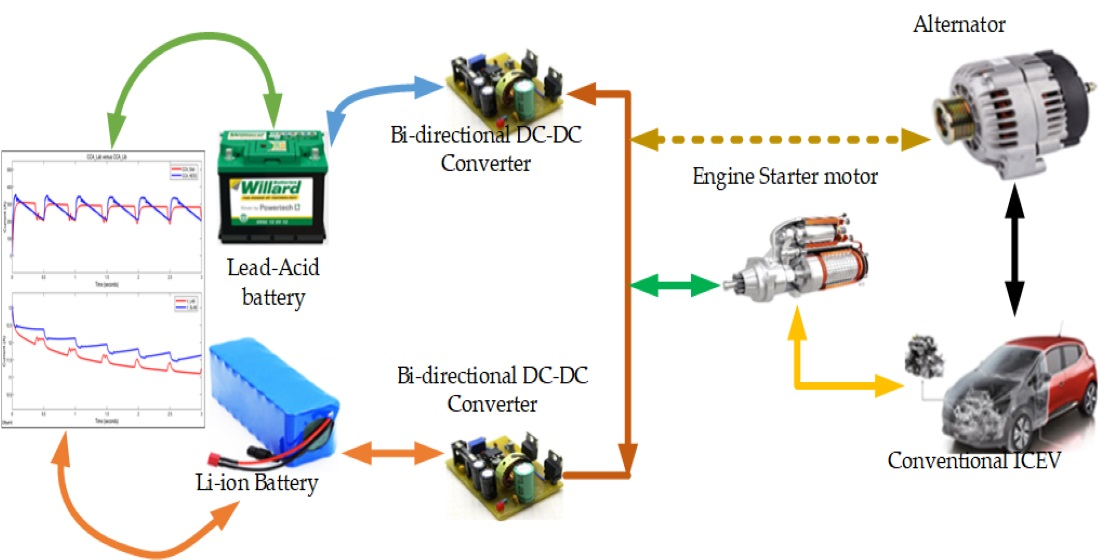
In this section, the study designs and models the proposed HESS and BMS for TVs. This includes battery modeling and the associated BMS using a fully active topology comprising bidirectional DC-DC buck-boost converters, fuzzy logic, and triple-loop controller, respectively. Besides, it addresses the percentage current sharing between ESSs in different conditions, minimum and maximum SoC limits during charging/discharging modes, and lifespan estimation. The vehicle electric system has the ICE as the main source of energy for the vehicle. It produces mechanical power (P
ice) from chemical energy. The mechanical power produced is divided into two parts, which include drive power P
dr that is used for propulsion and delivered to the alternator (P
alt), and then converted to electrical power. The alternator normally generates power to satisfy the power demand (P
D) for charging the HESS when it is necessary, as shown in
Figure 1.
3.1. ESS Modeling
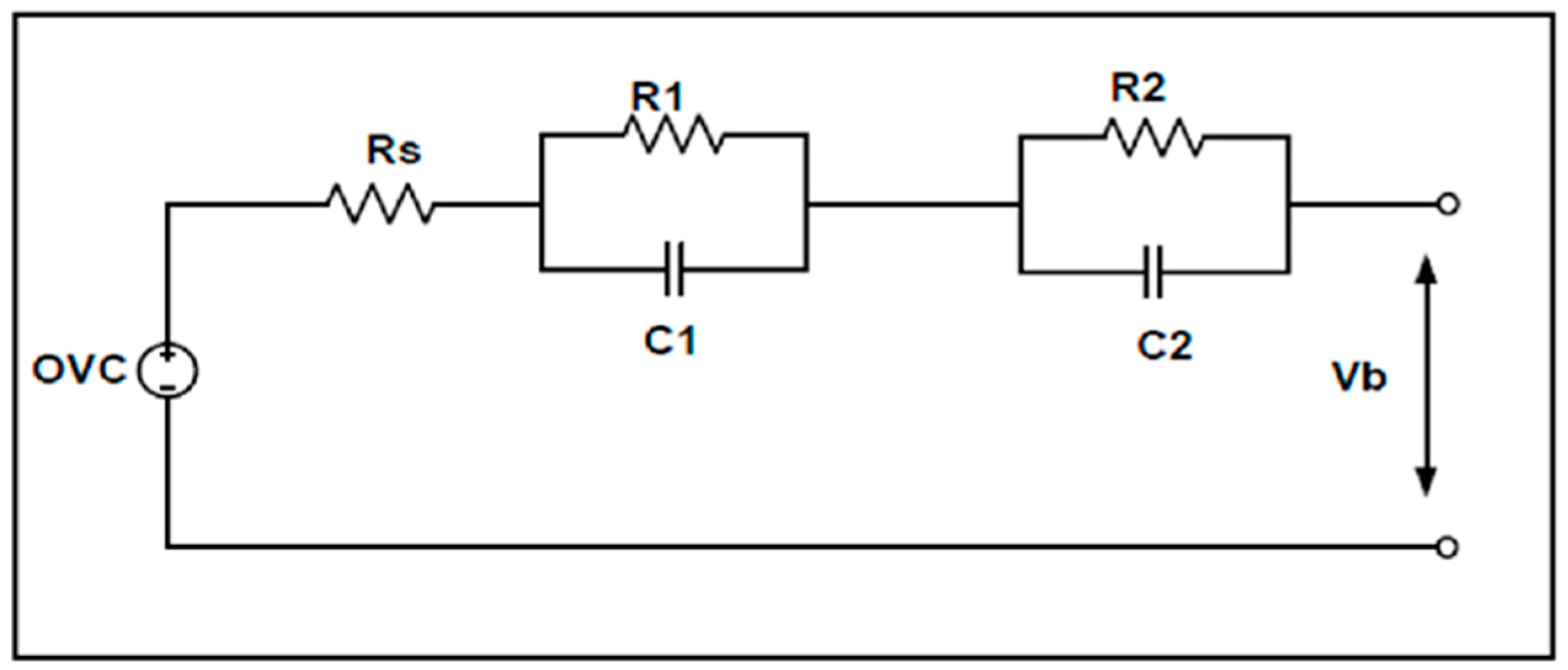
The battery type selection is based on the energy and power density, cycle life, charge/discharge rate, operating temperature, lifespan, cost, weight, and safety, respectively. The battery parameters are estimated using the equivalent circuit (RC network) model as shown in
Figure 2. This method is proposed because it is one of the best methods that gives accurate values between the battery computation requirements and voltage approximation, as indicated in [
31]. The battery model has four parameters, which include open-circuit voltage (OCV), series resistance, and parallel branch of resistance and capacitance. The OCV represents the voltage across the battery terminals under no-load conditions.
In
Figure 2, Rs is the internal resistor which normally varies with temperature. The OCV is the open-circuit voltage of the battery, which normally depends on
SoC. To determine the transient response of the voltage terminal, the circuit uses two parallel RC networks. The first parallel branch (R1 and C1) represents the small-time constant of the battery cell feedback, and it is used to model the double-layer capacitance and charge transfer procedures. The second parallel branch is for the lengthy-time constant of the battery cell feedback, which is used to model the diffusion procedure.
The MATLAB/Simulink library is used to model lead-acid and lithium-ion batteries for the proposed research. These battery parameters are contained in a library, which is changed according to the specification of the commercially available battery. The study estimates the battery parameters based on
Figure 2 and according to references [
31,
32].
The depth-of-discharge (DoD) is one of the main battery’s parameters. It directly depends on
SoC, which is vital to reduce the stress currently facing SLI batteries. The
SoC is defined as in Equations (1) and (2) and described in [
33]:
where
is the stored capacity at time
and
stand for the rated battery capacity. Whereas Equation (2) represents the storage capacity at time
, which is dependent on
representing the battery charging current. This current is normally assumed to be positive when the battery is discharging and negative when the battery is charging [
1,
31].
The voltage across the two
RC parallel branches in
Figure 2 is expressed as in Equations (3) and (4);
where
Vs represent a voltage drop in series resistance (i.e., internal resistance). Therefore, the total battery circulating current is represented by Equation (5);
where
is the battery current while
and
are the current through the resistance and capacitance in the parallel branches.
3.2. Bidirectional DC-DC Buck-Boost Converter Design
Here, in this section, the study discusses the design of the bidirectional DC-DC converters. The proposed bidirectional DC-DC buck-boost converter equivalent circuit is shown in
Figure 3 as stated in [
34].
Boost Mode Operation
In this mode, the battery works as a primary source. The current is normally continuous and has a ripple that depends on the value of the inductance and switching frequency. Since the rated voltage of the alternator is between 12 V and 14.5 V [
1,
4], the LAB’s voltage is 12 V and LIB’s is 12.8 V. The DC-DC converter steps the batteries’ voltage up to 13 V.
When S1 is on (closed), S2 is off (open) because of the complementary mechanism between the signal, which controls the two switches, the input voltage and inductor voltage are equal (i.e.,
=
) and expressed as in Equations (6) and (7);
where
is the inductance voltage,
is the minimum average current during the on state,
is the minimum current,
is the duty cycle, and
is the total time.
When S1 is off, switch S2 turns on. Then,
for this state is expressed as in Equations (8) and (9);
where
is the minimum average inductance current in off-state;
and
are the low and high voltages.
Moreover, Equations (10)–(12) are used to determine the converter parameters:
where
D is the duty cycle, and the value is between 0 and 0.99,
Vs is the DC input voltage supply from the batteries, and
Vo is the DC-DC converter output (13 V).
The inductance of the converters is determined as follows:
where
Io is the CCC, and
fs is the switching frequency (25 kHz).
The value of the capacitance is determined as in Equation (12):
where
is taken as 2% of
.
In this mode, the vehicle is in operation, and the alternator is producing more power than the required power of the vehicle. The bidirectional DC-DC buck-boost converter operates in a buck mode. It steps down the alternator voltage (i.e., from 14.5 V) to the required voltage to charge the batteries. The charging reference voltage of LAB is 13.1 V and 14.2 V for LIB.
When S2 is on, S1 is off, because of the complementary mechanism between the signals which control the two switches. Therefore,
is expressed as in Equation (13):
When S2 is off, S1 is on then
is expressed as in Equation (14):
The circuit parameters of the buck converter mode are derived and presented as in Equations (15) and (16):
where
is taken as 20% ×
.
The buck mode operation of the batteries, charging current, and voltage is controlled and determined by the BMS. The bidirectional DC-DC buck-boost converter parameters are summarized in
Table 1.
3.3. Battery Management Strategy
This section describes and discusses the battery management strategy development for an effective energy/power-sharing between the hybridized ESSs. The BMS proposed in this study manages the operation of HESS. The BMS is designed based on the required current and the characteristics of each battery technology. The proposed HESS with BMS operates in two modes as shown in
Figure 4 and
Figure 5. The discharging mode is when the HESS is supplying CCC to start the vehicle. The charging mode is when the HESS is being charged by the alternator.
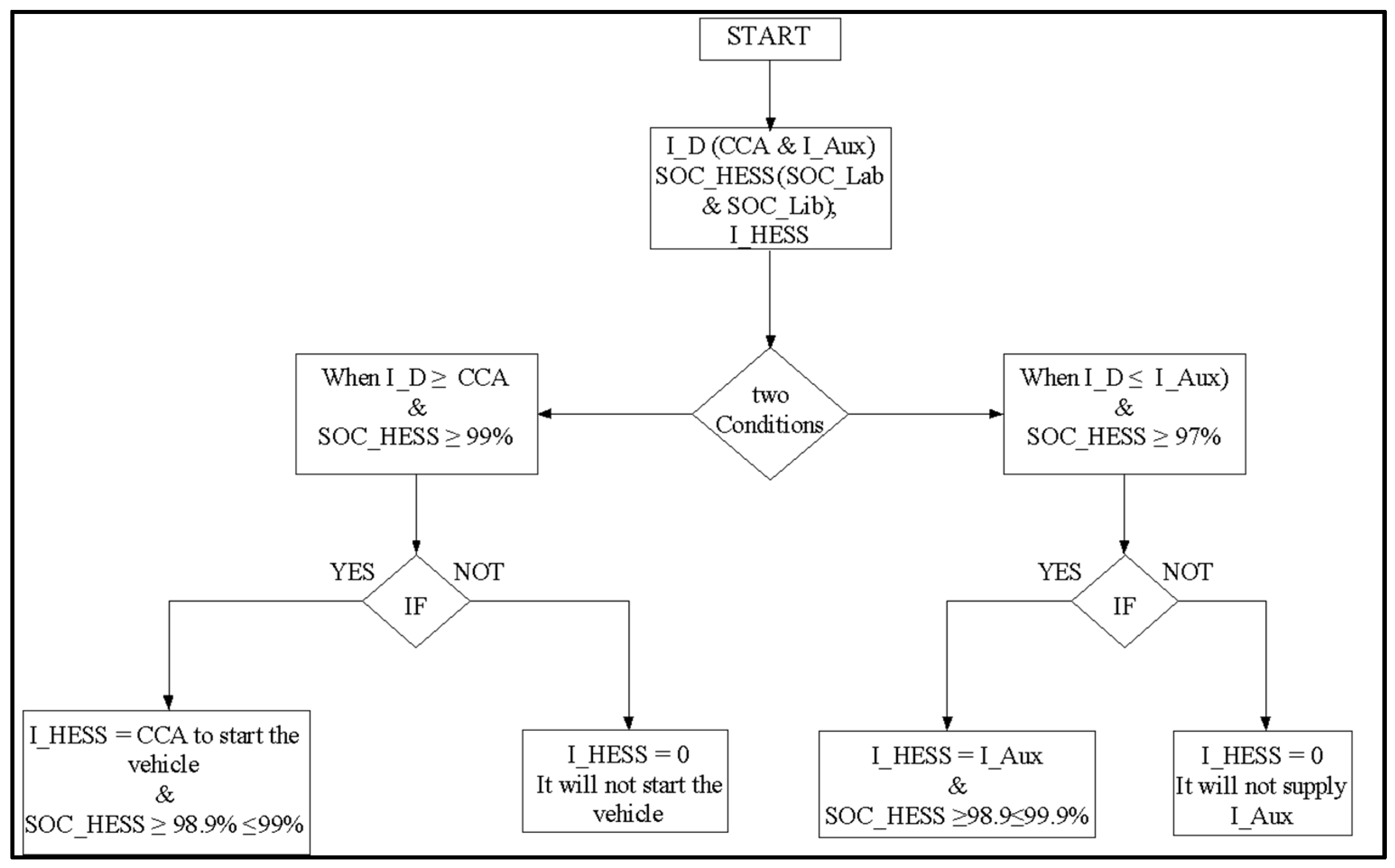
Figure 4 and
Figure 5 show the operation of the proposed HESS during charging and discharging modes. The HESS only discharges or charges if the following conditions are met.
During discharging mode: when and the , ( and ), which means that the HESS supplies the CCC to start the vehicle while maintaining the HESS SoC above 98.9%.
and the , which means that the HESS supplies the current for the auxiliary loads while maintaining the SoC above 98.9%.
During charging mode: , and , which means that the alternator supplies the current to the vehicle and simultaneously charges the batteries.
The high range SoC constraints is permitted because it helps protect the batteries from overcharging, and thus deep discharges, thereby enhancing their lifespan significantly.
3.3.1. Fuzzy Logic Control Design
The proposed FLC for this study has three inputs (, and ) and two outputs ( and ). The FLC is designed to give the reference current based on the to limit the minimum and maximum SoC of the batteries within a certain range, and to protect the battery from deep discharge and overcharge. The FLC consists of three parts, including fuzzification, inference, and defuzzification.
3.3.2. Fuzzification
The fuzzification presents the part of fuzzy logic control, which decides the input and output data into suitable language values [
35]. The fuzzification involves two processes: To derive the membership functions for the input and output variables and present them with linguistic variables. This process is equivalent to translating or plotting a classical set to a fuzzy set at varying degrees [
36]. The input variables of the proposed FLC are
,
, and
, where these membership functions are set between 0 and 350 A for CCA. This CCA value represents the maximum required cold cranking current for a vehicle that uses a 50 Ah battery capacity, whereas the variable percentage change in ESS
SoC is set between 0–100 during vehicle cranking. Equations (17) and (18) represent the
SoC change of LAB and LIB:
and
membership functions are set from 0 to 100, and the CCC/CCA is from 0 to 350 A. The input variables of the proposed FLC are computed in MATLAB/Simulink.. Moreover, the membership functions for the input variables are represented in
Table 2 and
Table 3.
The proposed FLC output membership function has two output variables (
and
) and each is set between −1 and 1, which represent the percentage CCA that the HESS supplies to the vehicle. The FLC allocates the reference percentage CCA, which the battery needs to supply. The positive current represents the HESS supplying the current to the vehicle and the negative current represents the HESS being charged from the alternator. The output membership function of the proposed FLC is summarized in
Table 4. The FLC is designed to give the CCA reference, which each battery needs to supply. The LIB is designed to supply between 30% and 50% of the required CCA, whereas the LAB supplies the remaining CCA.
Table 4 shows the output membership functions, whereas
Figure 6 shows the output membership in the MATLAB software tool (version 2019a, MathWorks, Natick, MA, USA).
Where:
is the membership function during the start-up function, and LAB supplies between 45% and 70% of the required current from the vehicles.
is the mode when there is no action from the HESSS, which means the HESS does not charge or discharge.
and : This is when the vehicle is in operation, and the alternator is producing more energy than required by the vehicle. The difference is used to charge the HESS.
The fuzzy inference system represents the fuzzy logic part where the decisions are made. The rules and database are developed and defined to meet the desired output. Fuzzy logic control rules are represented by understanding the knowledge of the human operator in the form of linguistic variables [
35,
36]. It is normally represented as a sequence of “IF-THEN” rules, leading to algorithms describing what action or output should be taken in action for the current observed information, which includes both input and feedback if a closed-loop control system is applied [
36]. The FLC “IF-THEN” rule associates a condition defined using linguistic variables and fuzzy sets to obtain a certain output. “IF” is normally used to capture the knowledge by using elastic conditions. THEN is used to give the conclusion or output in linguistic variable form. The proposed FLC has 6 rules and is summarized in
Table 5.
Where:
- IF
is Zero and ( & ) are L and M; THEN ( & ) is , which means that the HESS is charged by the energy produced from the alternator.
- IF
is CCA and ( & ) are H; THEN is (), which means that the HESS supplies the required current, where each battery supplies the current based on the reference current given by the FLC.
- IF
is CCA and & are not H; THEN is zero, which means that the system is balanced, and HESS does not charge or discharge.
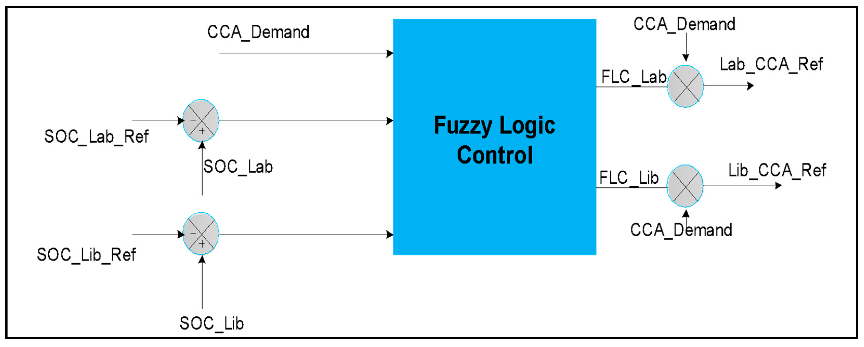
The defuzzification represents the FLC output. It produces quantifiable results in crisp logic based on the input membership, fuzzy rules, and corresponding degrees of processing fuzzy rules to a crisp set. The defuzzification method used in this proposed FLC is the centroid method. The FLC block diagram is shown in
Figure 7.
In
Figure 7, the main CCA demand, the difference between the LAB and LAB reference SoC, as well as the difference in LIB and LIB reference
SoC are the inputs to the fuzzy logic control. The circles with signs represent the summation blocks.
3.4. DC-DC Converter Control
This subsection discusses the design and control of bidirectional DC-DC converters as applied in this study. The bidirectional DC-DC buck-boost converters are controlled by pulse width modulation (PWM). The voltage and current of the bidirectional DC-DC buck-boost converters are controlled by the PI controllers. The control technique is performed by controlling the input voltage and generating the required output voltage and currents based on the reference voltage and current.
A triple-loop is used in each DC-DC converter to monitor the current and voltage during charging and discharging modes because LIBs operate reliably when charging criteria is a constant current-constant voltage regime with an optimized PI controller [
37]. The proposed triple-loop PI controller during charging and discharging modes is shown in
Figure 8. During discharging mode, the first PI controller controls the voltage ranges. The difference between the reference voltage (
) and the battery voltage (
) is sent to the PI controller for proper voltage level adjustments. The output of the PI is limited and multiplied with the reference CCC from the FLC. The difference between reference CCC with the battery current (
) proceed to the second PI, which is connected to the PWM DC generator that supplies the metal-oxide-semiconductor field-effect transistor (MOSFET) (i.e., S1 and S2). During charging mode, the difference between the reference charging voltage (
) and battery voltage
is sent to the PI controller, which generates the current charging reference
based on the characteristics of the battery, and it follows the same procedure as in the discharging mode.
In
Figure 8, a charging and discharging control is presented. It includes the battery voltage and its reference voltage as represented by the summation block (i.e., circle with x), the PI controller as represented in color blue, a rate limiter in color orange, and comparator, a PWM represented in red, as well as a binary “not” function in green.
The PI controller used for this investigation is found in the MATLAB/Simulink tool (version 2019a, MathWorks, Natick, MA, USA) library and the PI compensation factor is determined as in Equation (19):
where
stand for the compensation of the
PI controller.
The saturation output of the PI controller is set between 0 and 0.98. This setting is done because of the maximum possible duty cycle for the controller. The PWM generator has a 25 kHz switching frequency with a sampling time of s to switch the MOSFET on/off. The switching frequency is the same for calculating the equivalent parameters of the DC-DC buck-boost converter.
A combination of constant current—constant voltage methods is used to charge the batteries. The voltage and current charging references are determined by the current and voltage of the PI controller. The LAB is charged with a charging reference voltage of 13.1 V and 14.2 V for LIB, and as obtained from the datasheet of the batteries used in this research study. The HESS is charged at a constant current based on the nominal constant discharge current of the given batteries connected with a gain of −1, which represents the negative current during charging.
The batteries are connected in parallel, and each battery is connected in series with its bidirectional DC-DC buck-boost converter. The output of the two DC-DC converters is connected to the DC bus. The proposed BMS consist of (1) fuzzy logic control, which is used to allocate the CCC demand to the batteries and controls the batteries’ SoC during charging and discharging by ensuring that it remains within the desired limits (i.e., 98.5 to 99.99%) to avoid overcharge and deep discharge, and (2) the triple-loop PI controllers with PWM generator to control the desired voltage and current flow during charging and discharging modes.
3.5. Hybrid LAB and LIB Energy Storage Modeling
This subsection discusses the HESS modeling and its associated parameters. The battery technology operating points in a HESS are dependent on the current split between them. The sizing of HESS is based on a set of limitations defined by the specifications, such as the required starting current for ICE vehicle, system cost, and battery technology characteristics, respectively.
The proposed HESS replaces a single 12 V–50 Ah LAB manufactured by AutoX, South Africa, that provides a CCC of 350 A for 3 s. In the HESS, LIB is used as an auxiliary because of its longer lifespan compared to LAB. In contrast, LAB cost less compared to LIB. Thus, the HESS is developed to exploit the advantages of these technologies without affecting their efficiency and chemical composition. The shorter lifespan of LAB is compensated by the longer lifespan of LIB, whereas the high cost of LIB is compensated by the lower cost of LAB.
LIB is chosen based on its availability, size, and cost. Hence, 3.2 V–2.6 Ah Lithium-ion phosphate cells connected in series and parallel to meet the desired 12.8 V–5.2 Ah for the first case and 12.8 V–7.8 Ah for the second case are shown in
Table 6. The cells are assumed to be balanced. The hybridized batteries are each connected to a bidirectional DC-DC buck-boost converter. This converter steps up the batteries’ voltage to 13 V.
Table 7 shows the summary of the parameter of the single 12 V–50 Ah LAB and the proposed HESS. Also, it shows the parameters of the batteries used in this research study, which are determined based on availability, cost, and size.
Table 7 shows the parameters of single LAB (SLAB) and the proposed HESSs.
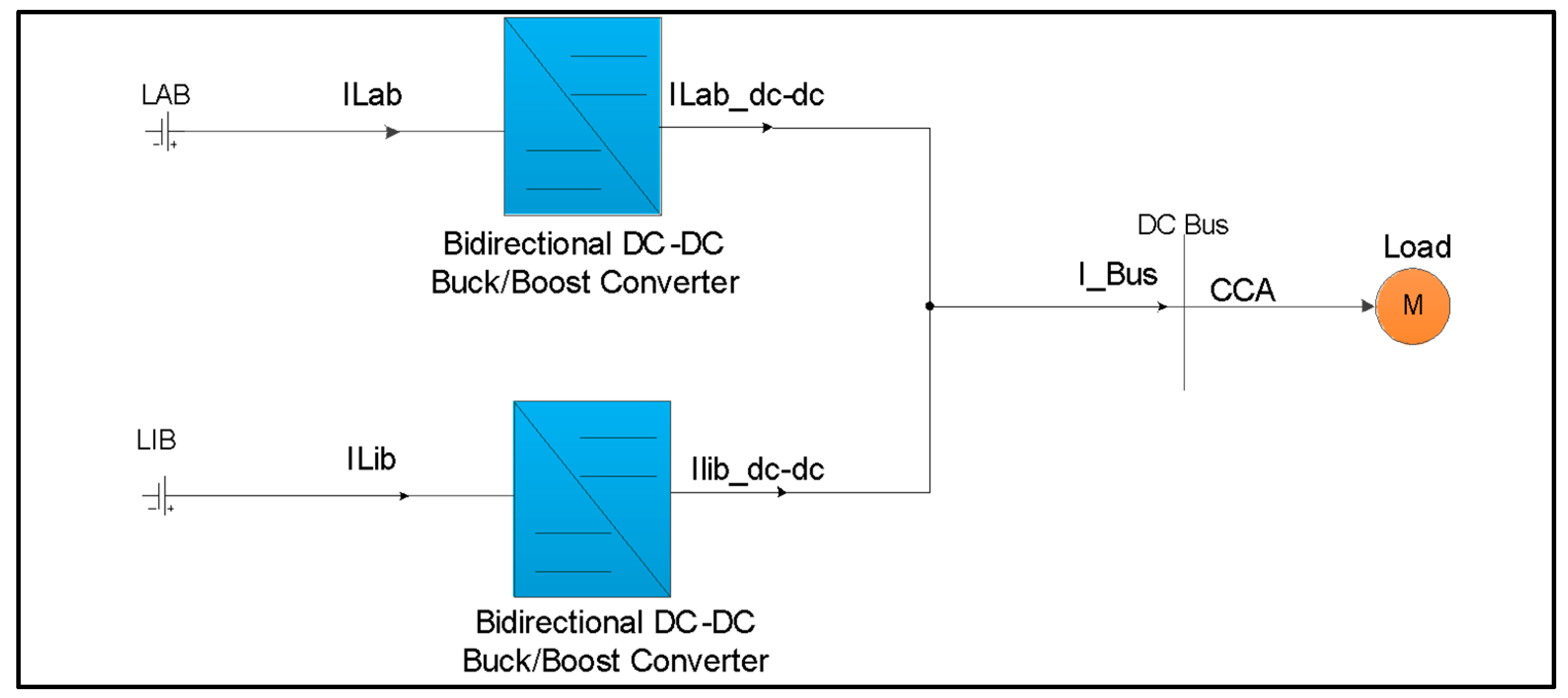
Figure 9 shows the proposed fully active topology with current flow of the proposed HESS.
In
Figure 9, the blue color blocks represent the bidirectional DC-DC converters and the orange circle represents the load of the vehicle, in this case the engine. The relationship between the required current for a vehicle is determined in the following sub-subsection by considering
Figure 9.
Starting Function of ICE (CCC)
In this mode, the batteries
SoC is assumed to be 100%, and the starting function is calculated using Equations (20)–(23):
where
and
are LAB and LIB current,
is the current demand;
is the reference output current of the LAB DC-DC converter, and
is the reference output current of the LIB DC-DC converter.
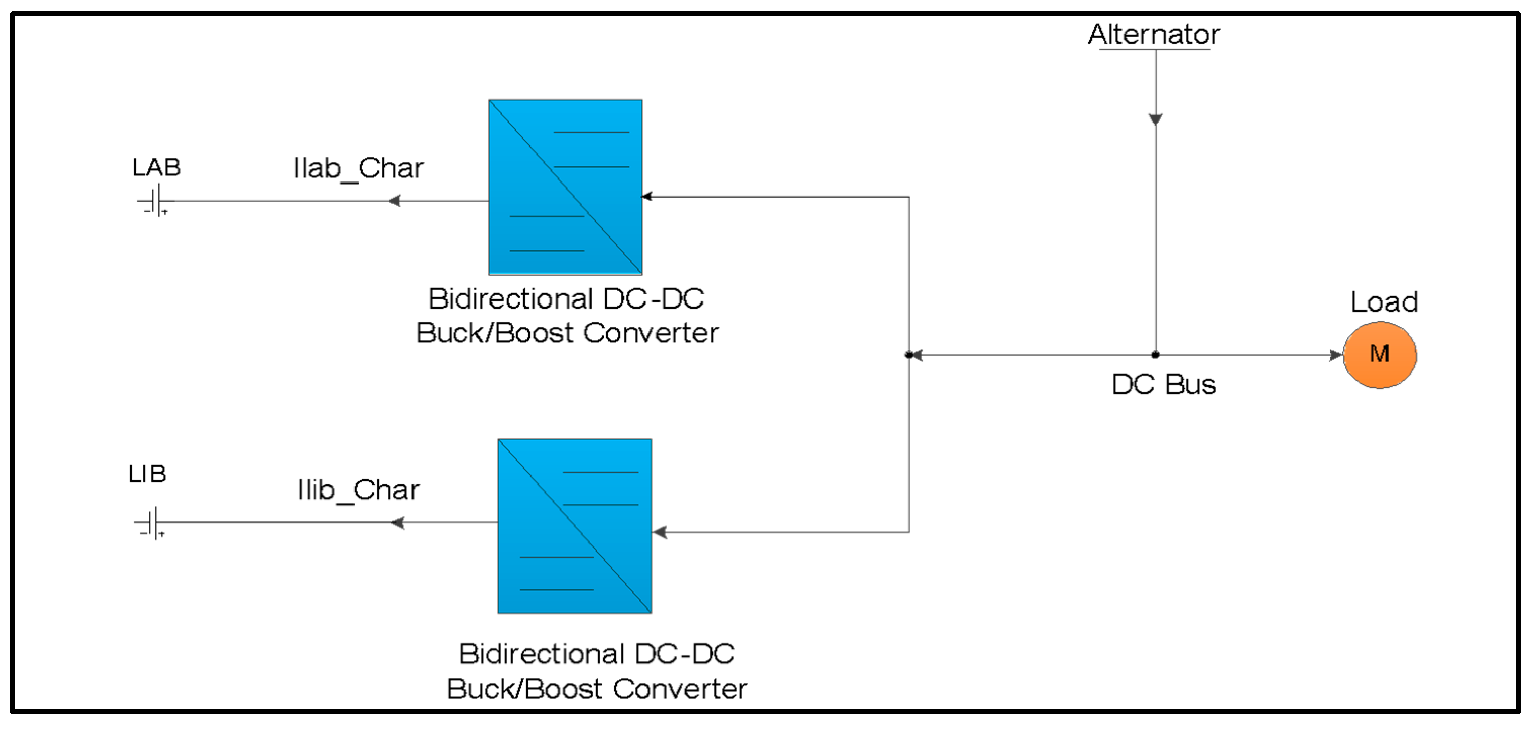
Figure 10 shows the TV electrical power system topology during charging mode. In this mode, the vehicle is operating, and the alternator is providing more than the required power for the vehicle. The alternator current is used to supply the vehicle and to charge the HESS.
The HESS charging current can be calculated using Equations (24)–(27) as follows:
where
is the alternator current,
is the HESS charging current,
and
are LAB and LIB charging currents,
is the bus current;
is the HESS charging power,
is the alternator power, and
is the power in the busbar.
3.6. Battery Lifespan Estimation
The battery life prediction model used in this research study accumulates losses of the battery based on discharge cycles [
27]. This type of model is called a fatigue model, which is one of the cycle counting approaches. Although the fatigue model is a high-level approximation for battery life, it is widely used due to its simplicity and clarity [
28,
29,
30]. Moreover, currently, there is widely specific and standardized method for battery life estimation. However, this study uses fatigue cycle-counting because of its associated merits. The short lifespan of lead-acid batteries is caused by short micro-cycles. However, these short micro-cycles may not really affect the lithium-ion battery because of their great life cycle compared to lead-acid battery. Therefore, the study highlights the lifetime span by considering the lead-acid battery and not lithium-ion because it is considered an auxiliary source for supporting the lead-acid battery. The fatigue models assume that each discharge of the battery affects the battery degradation. For the proposed lifetime estimation, the following scenarios are considered and used:
The curve showing the number of cycles of a battery as a function of DoD until it reaches the end of its lifetime. This curve is normally given by most battery datasheets. For this research study, the LAB FORBATT FB70-12G [
38] and LIB [
39] are used.
The SoC represents the capacity in percentage (%) of the battery.
Based on the data obtained from references [
38,
39], the loss-of-life (
LoL) and maximum expected lifespan in years of batteries are estimated according to authors [
28,
29,
30]. The
LoL of the batteries is the sum over all types of operation during the period of observation, where each discharge is considered. The
LoL is estimated using Equation (28):
where:
=, K is the DoD of the battery, i is the DoD used in an operation during a discharging mode. When is 100%, it means that the battery is fully discharged.
is the number of cycles performed at
DoD,
is the number of cycles to failure, which is reached when 80% of the battery capacity is used [
1]. The end life of a cycle in a battery with several
DoD is reached when
is equal to 1. It is further expressed as follows in Equations (29) and (30);
When = , then LoL = 1.
The battery lifespan can be represented by the maximum number of services (
) of the battery and represented by (29):
If the vehicle serves the number of operations (
) in a day, then the maximum expected lifespan of the battery is represented by Equation (30);
where
is the estimated lifespan,
is the number of cycles to failure, the number of operations, and
is the maximum number of services.
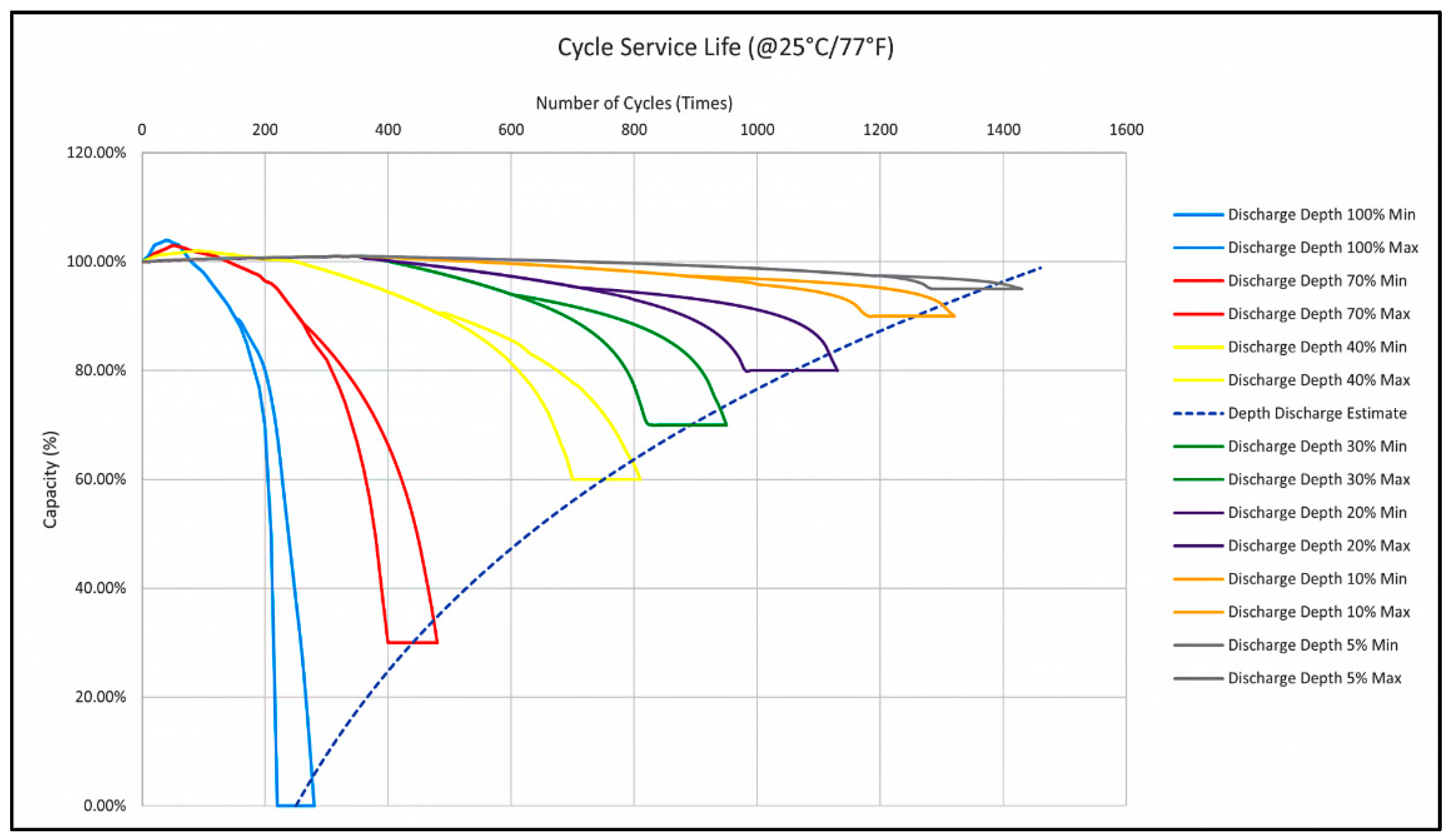
Figure 11 shows the extrapolated battery DoD concerning the battery capacity.
The full HESS with BMS is developed and simulated in a MATLAB/Simulink software tool (version 2019a, MathWorks, Natick, MA, USA). The proposed HESS with BMS using a fully active topology is presented. The HESS scheme comprises two bidirectional DC-DC buck-boost converters, FLC, and a triple-loop PI-based BMS controller. The FLC is developed to allocate the required CCA to the batteries and to control the minimum and maximum batteries’ SoCs. FLC has three inputs (CCADemand, ΔSoCLAB & ΔSoCLIB) and two outputs (LABCCAREF & LIBCCAREF) with their respective ranges. Six fuzzy rules are defined based on CCC and the charging modes. A triple-loop current and voltage PI controller with PWM DC generator is developed to control the current flow during charging and discharging, as well as to maintain the battery voltage and DC bus voltage within the required range during charging and discharging. Lifespan estimation using the fatigue cycle-life model approach is conducted.
4. Results and Discussions
This section presents and discusses the research results of the study. The proposed HESS is simulated for 125 s with the required CCA of 350 A for 3 s to crank the ICE. The HESS results are compared with a single 12 V–50 Ah LAB for the same required CCA. The current load demand for the two cases is created and generated using the Matlab/Simulink software tool (version 2019a, MathWorks, Natick, MA, USA).
Figure 12 shows the CCC fluctuating between 200 A and 350 A in a red line.
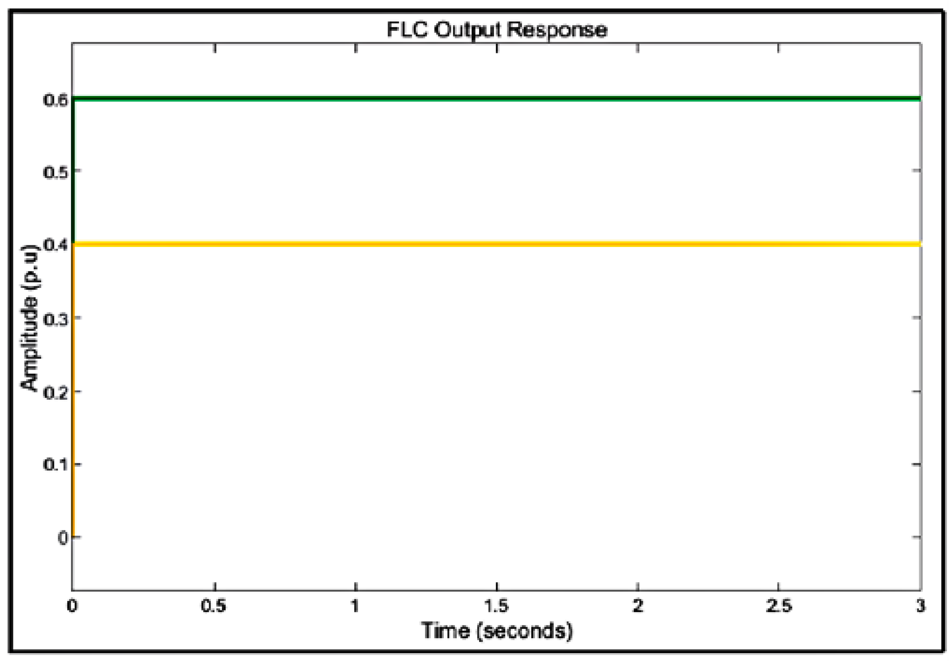
On the other hand,
Figure 13 shows the FLC rule output response. This response represents the percentage contribution of each battery during the discharging mode. LIB supplies 40% of the required CCA, and LAB supplies the remaining 60%. The percentage of CCA supplied by each battery depends on the CCA as well as the size and characteristics of the batteries.
In
Figure 13, the yellow line represents the current amplitude required to be supplied by LAB and the green line represents the current amplitude supplied by LIB in per unit value.
For cases one and two, the proposed HESS is simulated for 110 s in case one and 125 s in case two with the required CCA between 200A and 350 A for 3 s. Case one results are compared with a single 12 V–50 Ah LAB for the same required CCA.
Figure 14 shows the simulation results of the proposed HESS. The HESS delivers a maximum current of 359.8 A for case one.
The red line in
Figure 14 shows CCA demand and the blue line represents the CCA supplied by the HESS.
In
Figure 15, the HESS delivers a maximum current of 366.6 A. These values are greater than the required CCA of 350 A for 3 s.
After 3 s, the CCA demand is 0 A, which represents that the vehicle engine has started, and the bus voltage supplies the energy to the vehicle at the same time it charges the hybridized batteries.
The results show that the HESS is charged with a maximum charging current of −18 A and varies based on HESS’s SoC. The HESS has a maximum charging voltage of 14.5 V. As the SoC is close to 100%, the charging current is near to 0 A. When the battery is fully charged, the current is 0 A, and the battery voltage is reduced to the nominal battery voltage.
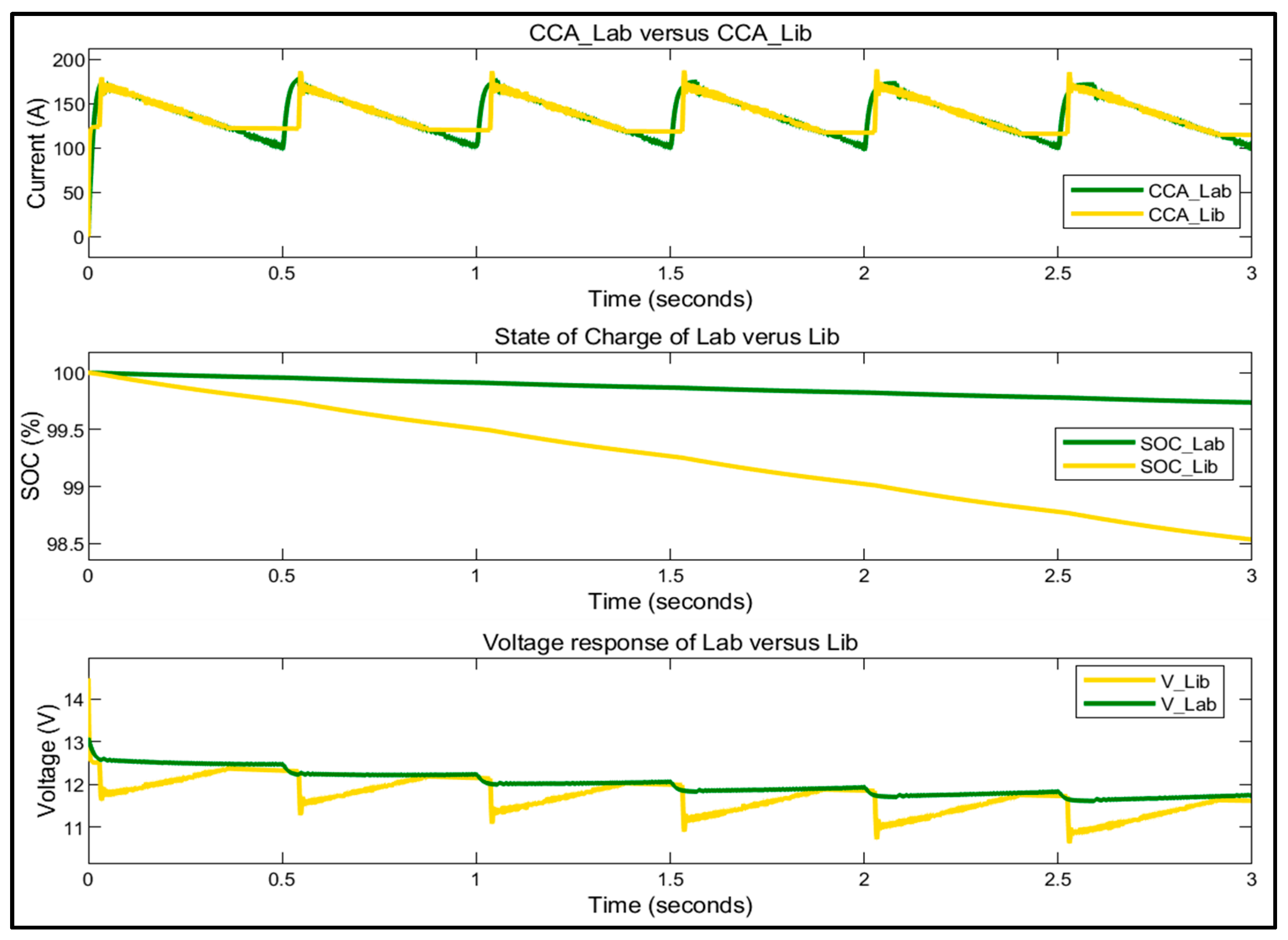
The percentage current supplied
SoC and voltage responses of the hybridized batteries during discharging mode are detailed and shown in
Figure 16,
Figure 17,
Figure 18 and
Figure 19. According to the results,
Figure 16, which shows that the LAB supplies 225.4 A for case one, represents that 62.7% of the required CCA is supplied by LAB, whereas the minimum voltage is 11.41 V and
SoC is 99.7%. On the one hand, LIB supplies 134.4 A, which represents 37.3% of the required CCA, whereas the minimum voltage of LIB is 10.04 V and
SoC is 98.33%. The existing minimum difference in voltages between the batteries is because of the different currents supplied by the batteries and the batteries’ size.
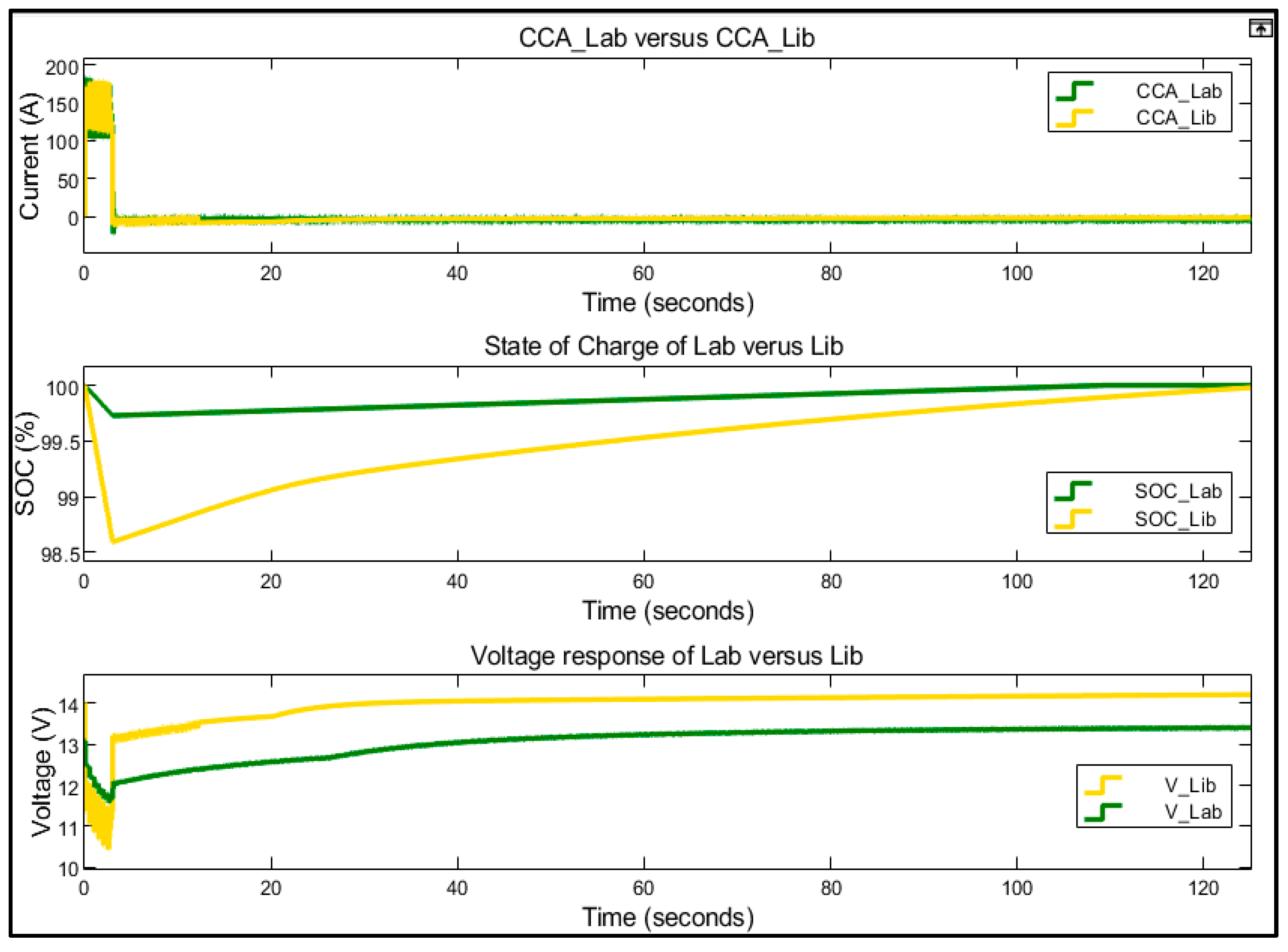
Figure 18 and
Figure 19 show the detailed simulation results of the current, voltage, and
SoC of the hybridized batteries during charging mode. Case one is charged for 107 s and case two for 122 s.
Figure 18 shows the detailed simulation results of the current, voltage, and
SoC of the hybridized batteries during charging mode. The HESS is charged for 120 s. The LAB’s
SoC fluctuates between 99.7% and 100%, whereas the voltage response increases from 11.46 V to the charging reference voltage of 13.1 V, and the charging reference current of −11 A. The LIB’s
SoC oscillates between 98.33% to 99.9%, whereas the voltage response increases from 10.04 V to the charging reference voltage of 14.2 V and the charging reference current of −4 A for case one. In case two, as shown in
Figure 19, LAB’s
SoC fluctuates between 99.7% and 100%, whereas the voltage response increases from 11.61 V to the charging reference voltage of 13.1 V and charging reference current of −11 A. The LIB’s
SoC is in the range of 98.53–99.9%, whereas the voltage response increases from 10.62 V to the charging reference voltage of 14.2 V and the charging reference current of −5 A. When the batteries are fully charged, the charging current is 0 A, and the charging voltage reduces to the initial nominal battery voltage. The charging current is negative since the direction of the current flow is opposite to that of the current supply during CCA mode. Although it is well agreed that maintaining high LIB
SoC harms its lifespan, which correspond to the low anode battery potential [
40], this study adopted the LFP battery because it does not show great capacity fade towards high
SoC. The reduced capacity fade in LFP is associated with their great voltage, which is lower and possesses high stability in relation to their lattice structure.
4.1. Proposed HESS Compared to SLAB
In this subsection, the proposed HESSs results are compared with SLAB to analyze the performance in terms of ICE starting capability and lifespan. A comparison is made based on CCA delivered by the proposed HESS and SLAB, as well as the minimum SoC, and voltage responses of LAB in HESS with SLAB during discharging mode to evaluate the delivered CCA and how it affects the SoC, voltage, and lifespan of the batteries.
The proposed case one and two of a 12 V–50 Ah HESS is compared with a single 12 V–50 Ah LAB during discharging mode for 3 s to analyze the performance in terms of ICE starting capability and lifespan improvement.
Figure 20 shows that the proposed HESS delivers 359.8 A, whereas the minimum voltage is 11.46 V. Meanwhile, the SLAB delivers 311.1 A, whereas the minimum voltage is 11.07 V.
Figure 21 shows that the minimum LAB’s
SoC after supplying the required CCA for 3 s is 99.7% and 99.26% for SLAB.
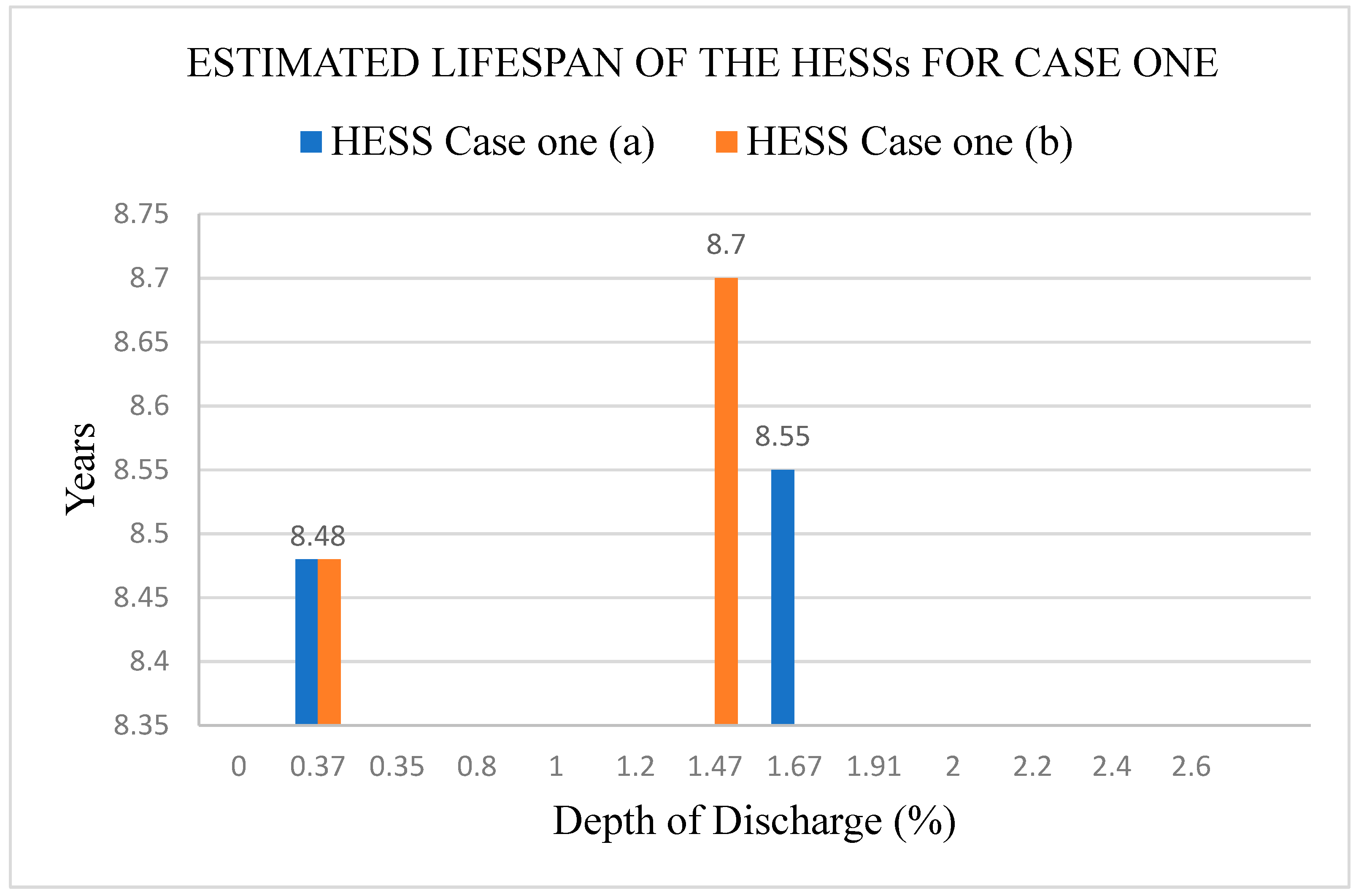
4.2. Estimated HESS Lifespan
The battery lifespan is estimated and plotted based on the simulation results discussed in
Section 4 and
Section 4.1 for both cases. The datasheets in [
38,
39] are used as the reference for LAB and LIB, respectively. The estimated and extended cycle service life graphs of the batteries (i.e., number of cycles versus DoD) are used to estimate the battery lifespan.
The data obtained from [
37,
38] are used with Equations (29) and (30) to estimate the batteries lifespan. The battery lifespan is predicted based on assumptions that the battery has a maximum service of 30 times per day (i.e., cranking the engine for 30 times a day) and an average surrounding temperature of ±25 °C.
Figure 22 shows the results of the estimated lifespan of the proposed HESS for case one and case two (represented as case one (b)). The years versus DoD graph is presented. The graph shows that the lifespan of the batteries is affected by DoD. In case one, the estimated lifespan of the LAB is 8.48 years and 8.55 years for LIB. For case two, the estimated lifespan for LAB is 8.48 years and 8.7 years for LIB.
Table 8 shows a summary of the proposed HESSs, where both cases are analyzed and compared based on the delivery of CCA, voltage, lifespan, and the cost of LIB. Case one shows the system’s excellent performance in terms of CCA delivery, voltage range, lifespan, and cost compared to case two.
Table 9 shows the summary results of the proposed HESSs for the two case studies compared with the SLAB.
Case one is simulated for 110 s and case two for 125 s. During CCA mode, the proposed HESS delivers 359.8 A for case one and 366.6 A for case two for 3 s. These values are greater than the required CCA of 350 A.
In case one, the LAB supplies 225.4 A, which corresponds to 62.7% of the required CCA, whereas the minimum voltage is 11.46 V and SoC is 99.7%. The LIB supplies 134.4 A, which corresponds to 37.3% of the required CCA, whereas the minimum voltage is 10.04 V and SoC is 98.33%. During charging mode, LAB is charged with a charging reference voltage of 13.1 V and a charging reference current of −11 A. The LIB is charged with a charging reference voltage of 14.2 V and with a charging reference current of −4 A for 107 s. The charging current is negative since the flow of current is opposite to that of the current supply during CCA mode.
In case one, LAB supplies 180 A, which corresponds to 49% of the required CCA, whereas the minimum voltage is 11.61 V and SoC is 99.7%. The LIB supplies 186.6 A, which corresponds to 51% of the required CCA, whereas the minimum voltage is 10.61 V and SoC is 98.53%. The LIB is charged with a charging reference voltage of 14.2 V and a charging reference current of −4 A for 122 s.
The results show that case one performs much better than case two in terms of the current delivered, voltage, SoC, lifespan, and cost of the batteries, respectively. Thus, case one is chosen to provide the required ICE starting functions.
The proposed HESS for case one is compared with a single 12 V–50 Ah LAB. A comparison is made based on CCA delivered by HESS and SLAB, as well as the minimum voltage, and SoC level of LAB in HESS and SLAB during CCA mode. The results show that the HESS delivers 359.8 A, whereas its minimum LAB voltage is 11.46 V and SoC is 99.7%. While the SLAB delivers CCA of 311.1 A, the minimum voltage is 11.07 V, and SoC is 99.26%, respectively.
Consequently, the results show that the proposed HESS for case one significantly improves the performance of the LAB in terms of delivered CCA and lifespan.
The performance of LAB in terms of CCA delivered is improved by 13.5%, while the LAB voltage range and
SoC remain significantly higher compared to SLAB. The estimated lifespan of the proposed HESS for case one is 8.5 years compared with the estimated lifespan of the SLAB which is currently 5.1 years. The outcome of the study shows that the LAB lifespan is significantly enhanced by 3.4 years. The proposed HESS provides immense benefits to the automobile industry in terms of providing a battery system with sustained capacity and long lifespan. Despite many commercially available LIBs for SLI reported in [
41] from different manufactures, none of the batteries match the HESS provided in terms of capacity matching. Besides, Noh et al. [
42] suggest the LIB cranking capability estimation algorithm. However, the process for estimating the cranking capability has low accuracy and great computational burden. Moreover, Liu et al. [
43,
44] provides insights on the relationship between the effect of ambient temperature and charging/discharge current on LIB performance, as well as further understanding on the effect of the distribution of transient temperature on these batteries as used for SLI. However, the testing procedure applies only to current control and ignores the voltage control. Besides, the other study does not elaborate on the temperature distribution during engine cranking, which is critical for LIBs.
5. Conclusions
The proposed hybrid Lead-acid and Lithium-ion energy storage system with BMS is designed, developed, and simulated using MATLAB/Simulink software. The HESS operation is controlled using BMS based on a fully active topology and comprises two bidirectional DC-DC buck-boost converters, fuzzy logic control for effective energy/power-sharing between the ESSs, and a triple-loop PI controller to monitor and limit the current required for the vehicle load demand. The two bidirectional DC-DC buck-boost converters step up the batteries’ voltage to 13 V during CCA mode. During charging mode, the bidirectional DC-DC buck-boost converter steps down the DC bus voltage from 14.5 V to the charging reference voltage of 13.1 V for LAB and 14.2 V for LIB. The FLC is used to divide the required CCA between the batteries. This division is made based on a set of rules that defines the operation of HESS during the discharging mode. Besides, it ensures that minimum and maximum batteries’ SoC are within the permissible limits to avoid deep discharge and overcharging. The LIB (i.e., LFP) is kept at considerable SoC to ensure that it assists LAB efficiently during vehicle starting function and provides 40% of the total cold cranking current required, while LAB gives 60%. Thus, the life of the LAB as well as the hybrid battery is considerably enhanced by avoiding the deep discharge of LAB during the cranking period.
The triple-loop PI controller with a PWM DC generator is used to control the voltage range and to limit the current flow of the hybridized batteries during charging and discharging mode. In discharging mode, the triple-loop PI controller obtains the reference CCA from FLC and generates the desired CCA output based on the reference CCA from FLC. During discharging mode, the triple-loop PI controller gives the required charging reference current to protect the batteries being charged with high current.
The proposed HESS is compared with a single 12 V–50 Ah LAB. A comparison is made based on CCA delivered by HESS and SLAB, as well as the minimum voltage, and SoC level of LAB in HESS with SLAB during CCA mode. The results show that the performance of LABs in terms of storage capacity is improved by 13.5%, while the LAB voltage range and SoC remain significantly higher compared with SLAB. The estimated lifespan of the proposed HESS for case one is 8.5 years compared with the estimated lifespan of the SLAB which is 5.1 years. The results clearly show that based on the fatigue cycle-count model, the LAB’s lifespan is significantly enhanced by 3.4 years. Although various method for battery life estimation exists, this study uses the fatigue cycle counting method to estimate the battery lifespan. This method may not be suitable for operation in such low micro-cycles. To validate the suitability of this method for operation in such micro-cycles, this study proposes to develop a prototype and include the calendar lifespan estimation in the future using tools such as python battery analysis modelling (PyBAM) or via the simulation of stationary energy storage (SimSES) for a clear comparison between fatigue and calendar lifespan estimation.


