
Reduction in the Cogging Torques in the DCEFSM Motor by Changing the Geometry of the Rotor Teeth


Abstract
:1. Introduction
2. Materials and Methods
- Minimizing the amplitude of the pulsation of the total machine torque;
- Minimization of the maximum value of the cogging torque and obtaining a smooth curve of it as a function of the rotor position (i.e., minimization of the derivative value dTc/dϕ);
- Obtaining the value of the maximum motor starting torque not lower than 95% of its current maximum value;
- Obtaining the value of the rated torque of the motor not lower than 95% of its current value.
3. Results
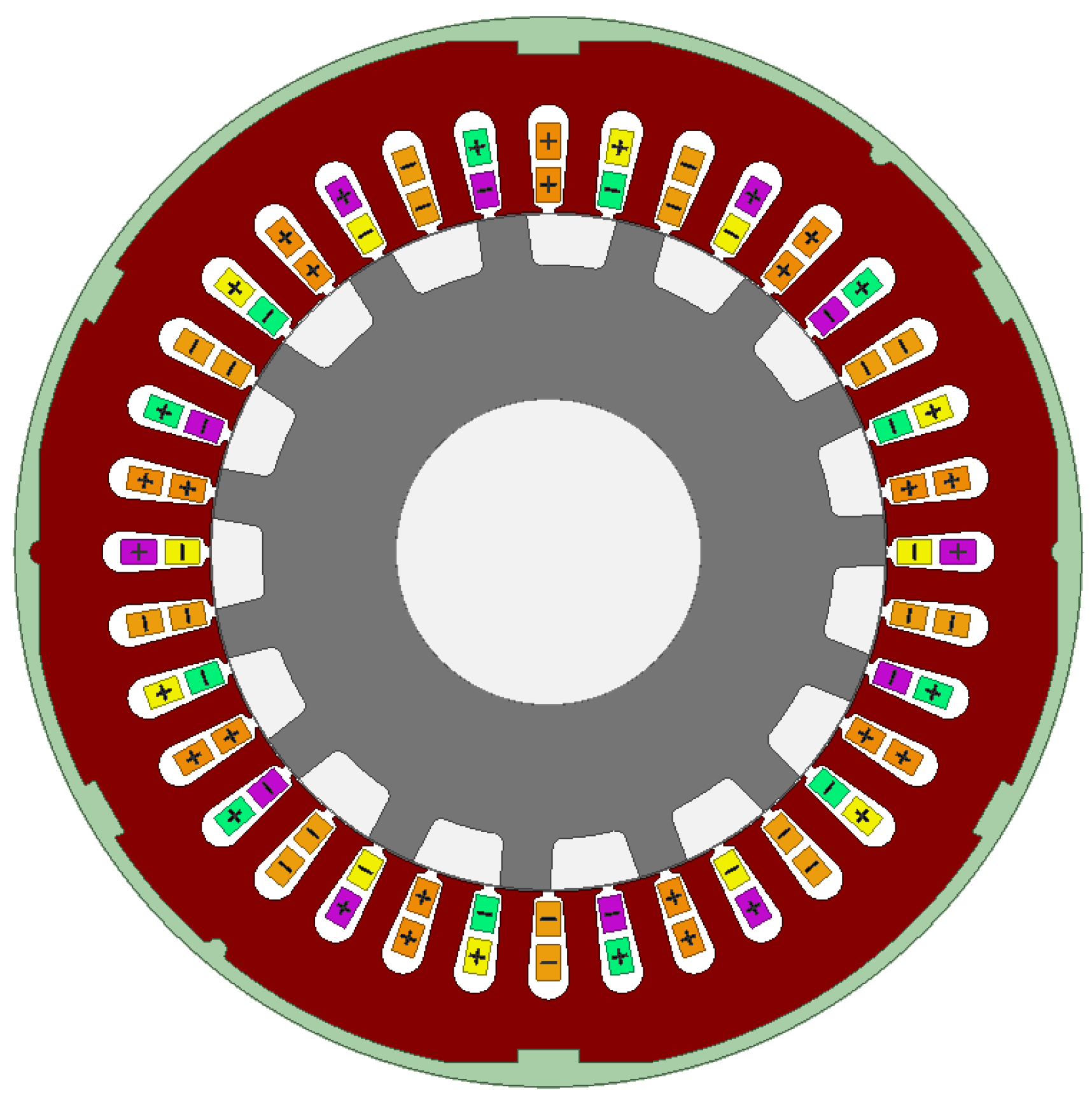
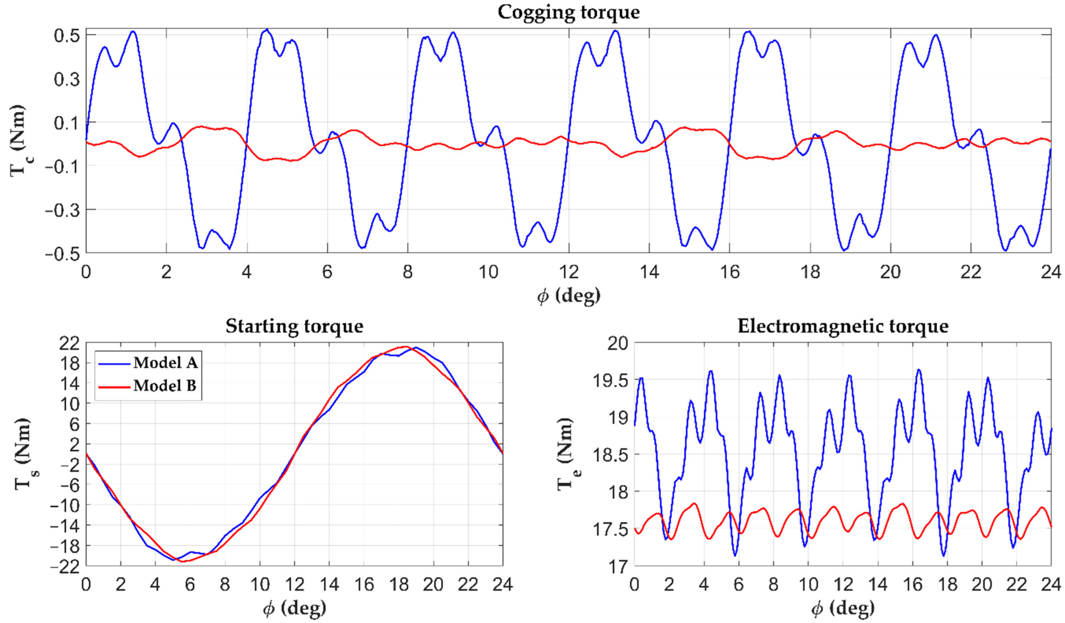
3.1. Rotor with Original Teeth (Model A)
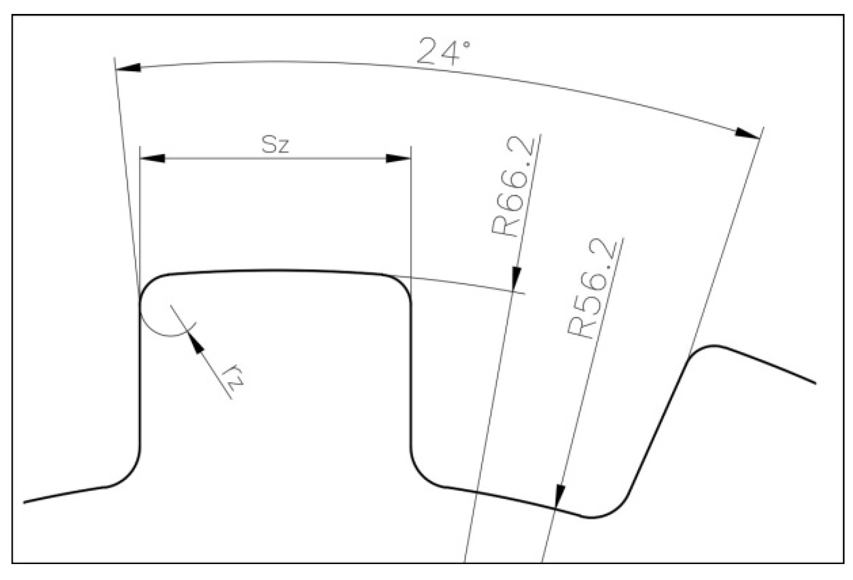
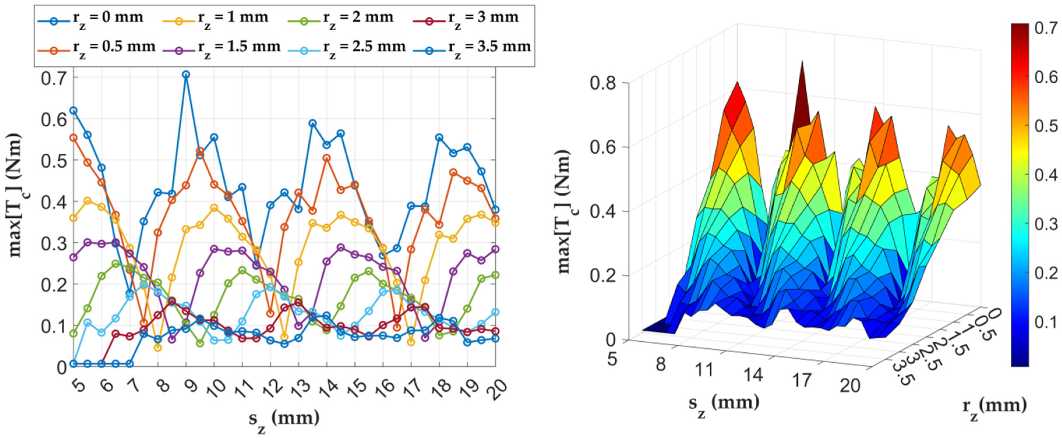
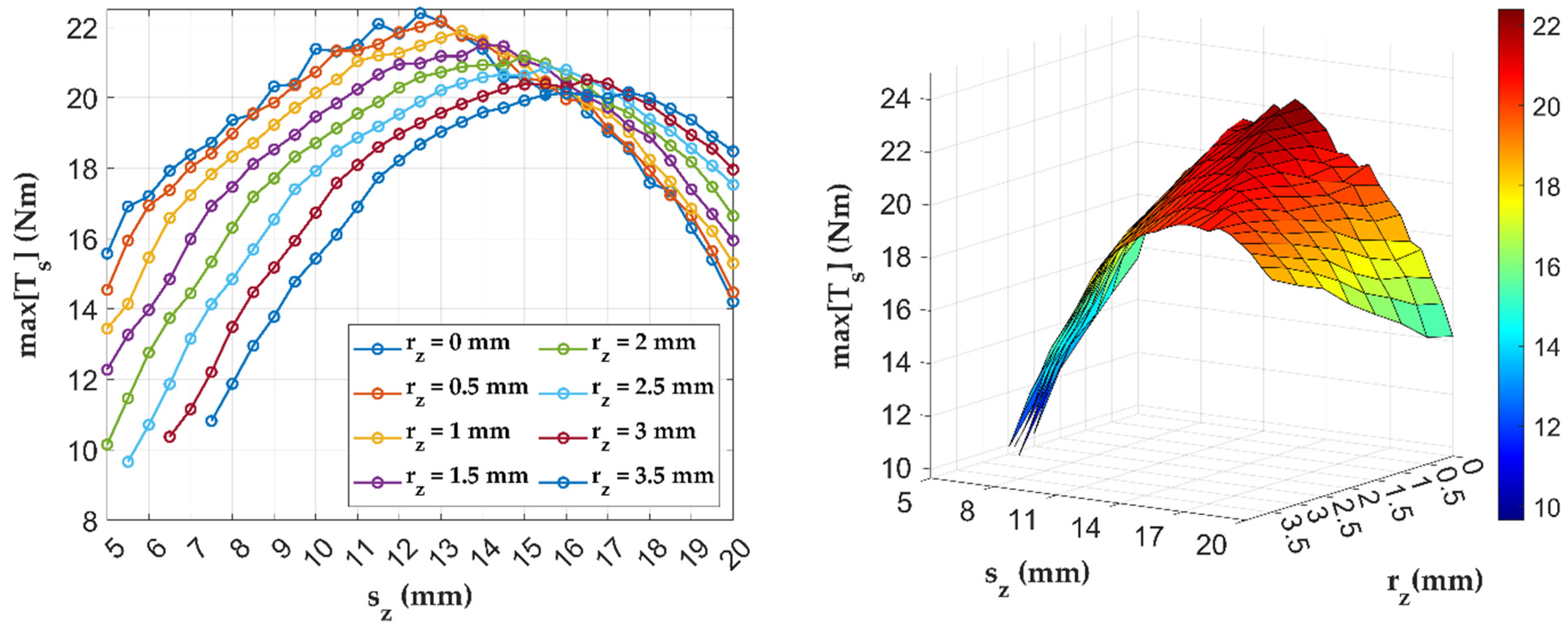
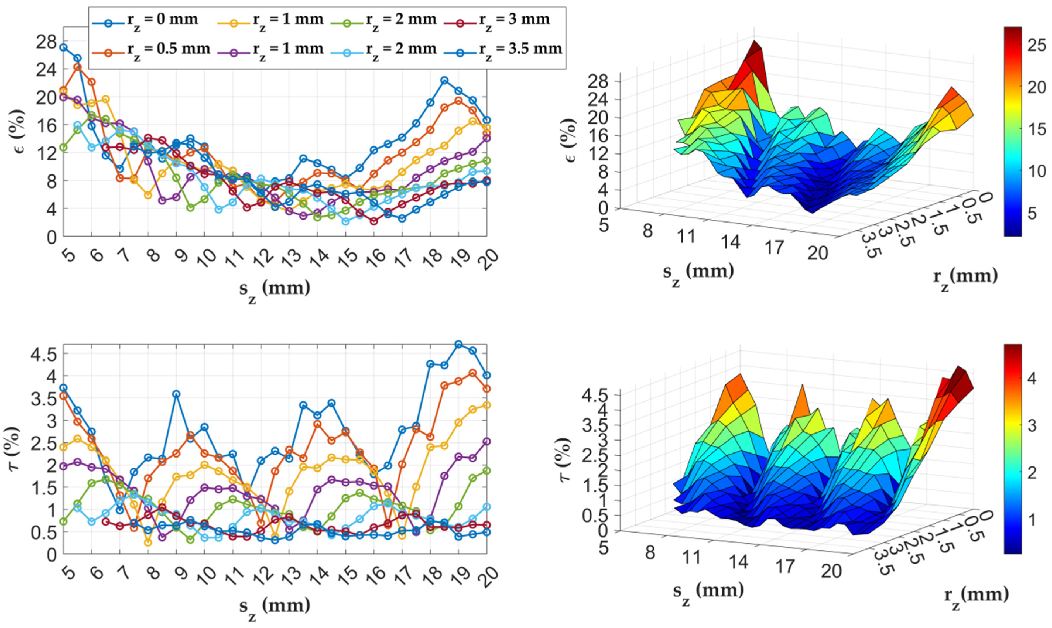
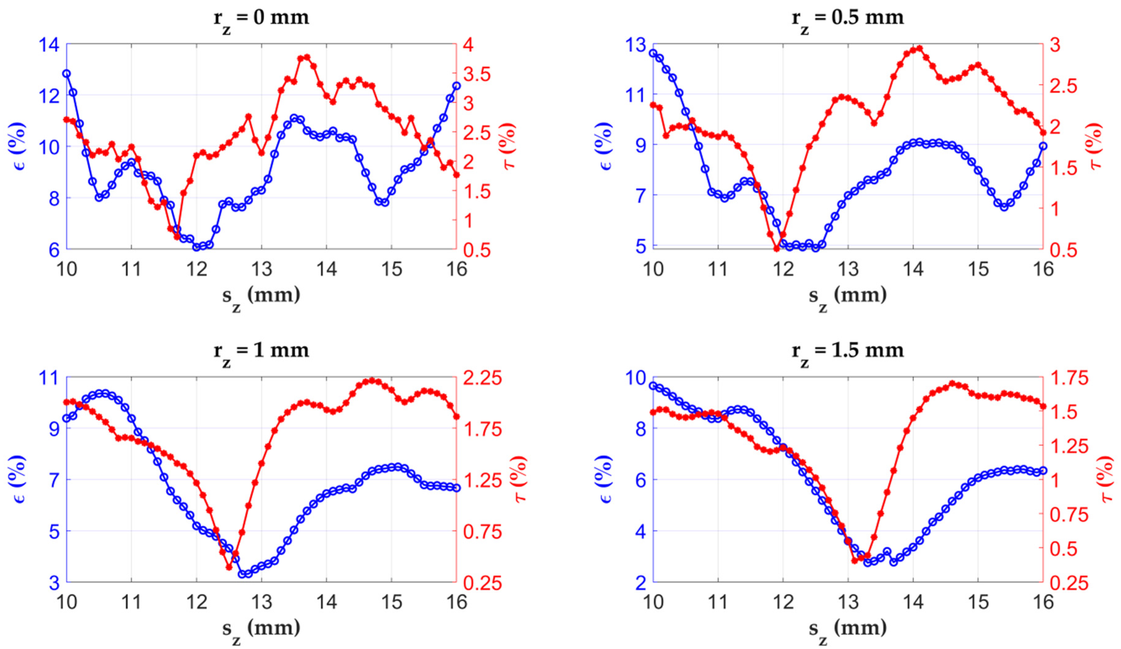
3.2. Rotor with Changed Tooth Width and Tooth Corners Radius (Model B)
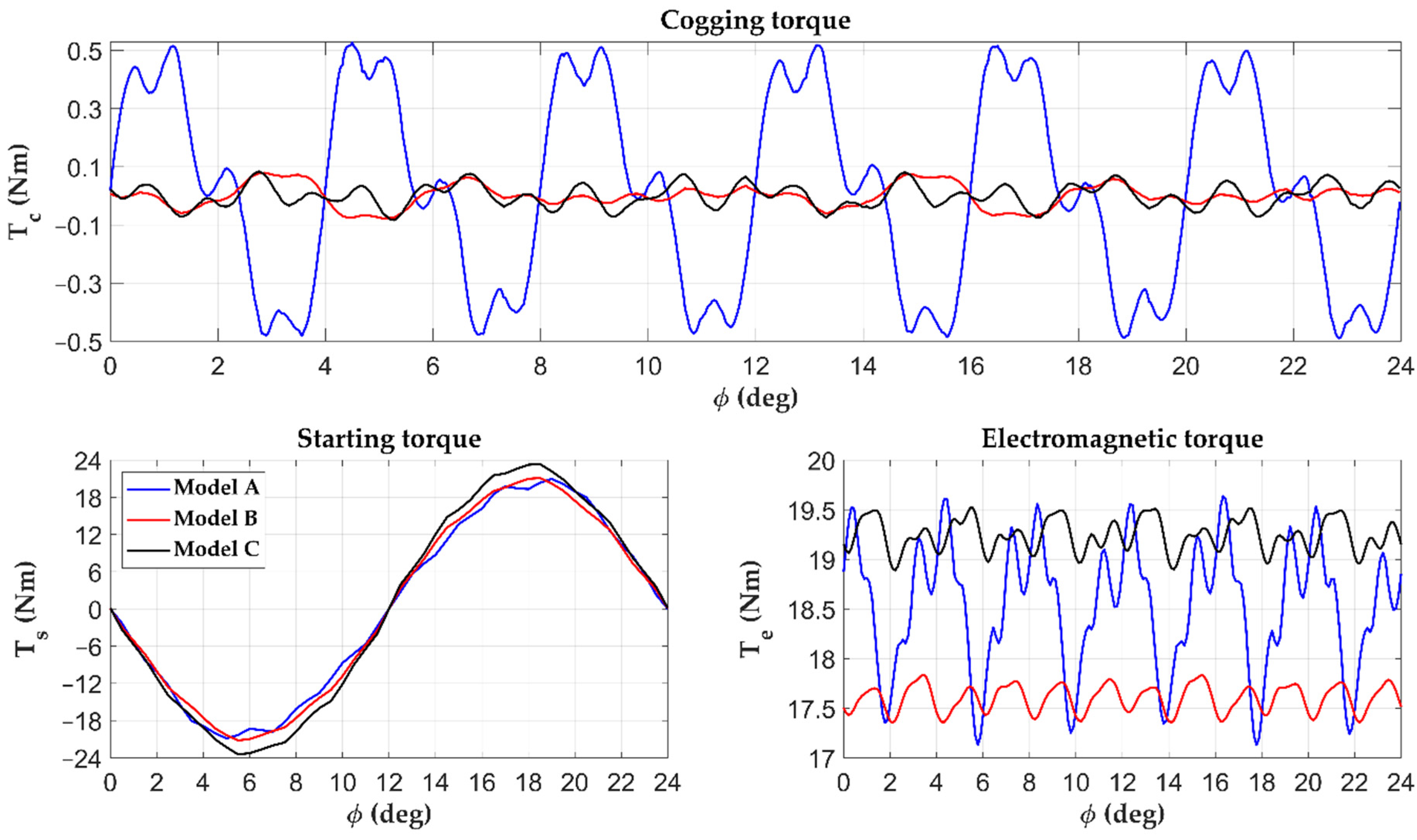
3.3. Influence of the Air Gap Size on the Cogging Torque
4. Discussion
5. Conclusions
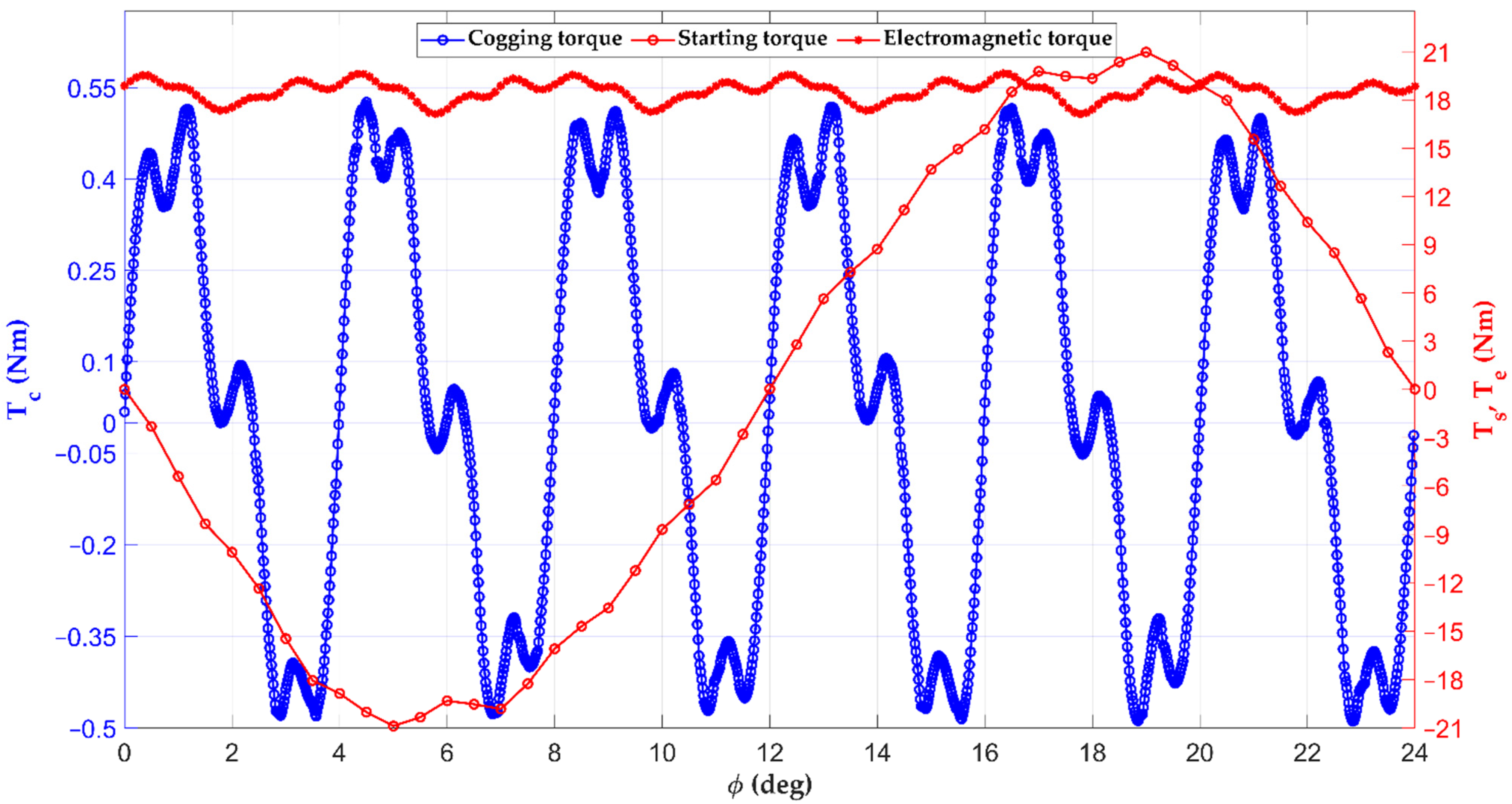
- It is possible to significantly (more than six-fold) limit the maximum value of the cogging torque in the DCEFSM motor only by changing the geometry of the rotor teeth and the size of the air gap. This does not reduce the operating torque and starting torque of the motor.
- Rounding the corners of the rotor teeth, which is generally not practiced in electrical machines, has a significant impact on the cogging torque. It also helps to reduce the value of the dTc/dϕ derivative, which affects the smoothness of the rotor movement during rated motor operation.
- The dependence of the cogging torque on the size of the air gap is non-linear, i.e., with saturation. This made it possible to select the correct size of the air gap, guaranteeing the minimization of the cogging torque while maintaining the values of the operating and starting torques.
- Calculations showed that it is not possible to further increase the operating torque of the machine by changing the geometry of the rotor teeth and the size of the air gap. The operating torque can be increased only by increasing the value of the field current and/or the armature current. Unfortunately, this will require enlarging the stator slots, for the field winding and/or for the armature winding.
Author Contributions
Funding
Institutional Review Board Statement
Informed Consent Statement
Data Availability Statement
Conflicts of Interest
References
- Drabek, T.; Kara, D.; Kołacz, T.; Lerch, T.; Skwarczyński, J. Measurement Tests and FEM Calculations of DC Excited Flux Switching Motor Prototype. Energies 2021, 14, 4353. [Google Scholar] [CrossRef]
- Caruso, M.; di Tommaso, A.O.; Emma, S.; Miceli, R. Analysis, characterization and minimization of IPMSMs cogging torque with different rotor structures. In Proceedings of the Twelfth International Conference on EVER, Monte Carlo, Monaco, 11–13 April 2017; IEEE Eindhoven University of Technology: Eindhoven, The Netherlands, 2017. [Google Scholar]
- Sangdehi, S.M.K.; Abdollahi, S.E.; Gholamian, S.A. Cogging Torque Reduction of 6/13 Hybrid Excited Flux Switching Machine with Rotor Step Skewing. In Proceedings of the 5th Conference on Knowledge Based Engineering and Innovation (KBEI), Tehran, Iran, 28 February–1 March 2019. [Google Scholar]
- Ueda, Y.; Takahashi, H. Transverse-Flux Motor Design with Skewed and Unequally Distributed Armature Cores for Reducing Cogging Torque. IEEE Trans. Magn. 2017, 53, 1–5. [Google Scholar] [CrossRef]
- Goryca, Z.; Różowicz, S.; Różowicz, A.; Pakosz, A.; Leśko, M.; Wachta, H. Impact of Selected Methods of Cogging Torque Reduction in Multipolar Permanent-Magnet Machines, a DC motor without magnets or brushes. Energies 2020, 13, 6108. [Google Scholar] [CrossRef]
- Knypiński, Ł.; Nowak, L. The algorithm of multi-objective optimization of PM synchronous motors. Przegląd Elektrotechniczny 2019, 95, 242–245. [Google Scholar] [CrossRef]
- Bernatt, J. Electrical and Magnetic Circuits of Electrical Machines Excited with Permanent Magnets; Research and Development Centre of Electrical Machines Komel: Katowice, Poland, 2010. [Google Scholar]
- Drabek, T.; Matras, A.; Skwarczyński, J. Simulation of permanent magnet synchronous machine. Przegląd Elektrotechniczny 2008, 84, 38–41. [Google Scholar]
- Anuja, T.A.; Doss, M.A.N. Reduction of Cogging Torque in Surface Mounted Permanent Magnet Brushless DC Motor by Adapting Rotor Magnetic Displacement. Energies 2021, 14, 2861. [Google Scholar] [CrossRef]
- Goryca, Z.; Paduszyński, K.; Pakosz, A. The influence of asymmetrical distribution of rotor’s magnets on the cogging torque of the multipolar machine. In Proceedings of the 18th International Symposium on Electromagnetic Fields in Mechatronics, Electrical and Electronic Engineering (ISEF) Book of Abstracts, Lodz, Poland, 14–16 September 2017. [Google Scholar]
- Zhu, W.H.X. Cogging Torque Suppression in Flux-Switching Permanent Magnet Machines by Superposition of Single Rotor Tooth. In Proceedings of the IEEE Energy Conversion Congress and Exposition (ECCE), Portland, ON, USA, 23–27 September 2018. [Google Scholar]
- Bao, J.; Gysen, B.L.J.; Boynov, K.; Paulides, J.J.H.; Bastiaens, K.; Lomonova, E.A. Analysis and minimization of torque ripple for variable flux reluctance machines. In Proceedings of the IEEE International Electric Machines and Drives Conference (IEMDC), Miami, FL, USA, 21–24 May 2017. [Google Scholar]
- García-Gracia, M.; Jiménez, A.R.; Martín, S.A. Cogging Torque Reduction Based on a New Pre-Slot Technique for a Small Wind Generator. Energies 2018, 11, 3219. [Google Scholar] [CrossRef] [Green Version]
- Dobzhanskyi, O.; Gouws, R.; Amiri, E. Optimal switching-flux motor design and its cogging effect reduction. In Proceedings of the IEEE 58th International Scientific Conference on Power and Electrical Engineering of Riga Technical University (RTUCON), Riga, Latvia, 12–13 October 2017. [Google Scholar]
- Sulaiman, E.; Romalan, G.M.; Halim, N.A. Skewing and notching configurations for torque pulsation minimization in spoke-type interior permanent magnet motors. In Proceedings of the International Conference on Control, Electronics, Renewable Energy and Communications (ICCEREC), Bandung, Indonesia, 13–15 September 2016. [Google Scholar]
- Cui, Y.; Zhang, F.; Huang, L.; Chen, Z. Analysis and Verification of a Cogging Torque Reduction Method for Variable Flux Memory Permanent Magnet Machine. Electronics 2021, 10, 1913. [Google Scholar] [CrossRef]
- Bao, J.; Gysen, B.L.J.; Boynov, K.; Paulides, J.J.H.; Lomonova, E.A. Torque Ripple Reduction for 12-Stator/10-Rotor-Pole Variable Flux Reluctance Machines by Rotor Skewing or Rotor Teeth Non-Uniformity. IEEE Trans. Magn. 2017, 53, 1–5. [Google Scholar] [CrossRef] [Green Version]
- Pompermaier, C.; Washington, J.; Sjöberg, L.; Ahmed, N. Reduction of cogging torque in transverse flux machines by stator and rotor pole shaping. In Proceedings of the IEEE Energy Conversion Congress and Exposition (ECCE), Milwaukee, WI, USA, 18–22 September 2016. [Google Scholar]
- Awah, C.C.; Okoro, O.I.; Chikuni, E. Cogging torque and torque ripple analysis of permanent magnet flux-switching machine having two stators. Arch. Electr. Eng. 2019, 68, 115–133. [Google Scholar]
- You, Z.C.; Yang, S.M. Control System for a Single-Phase DC-Excited Flux-Switching Machine with a Torque Ripple Reduction Scheme. IEEE Access 2020, 8, 226579–226590. [Google Scholar] [CrossRef]
- You, Z.C.; Yang, S.M. Modeling Torque Characteristic of Single-Phase DC-Excited Flux Switcing Motor for Torque Ripple Reduction. In Proceedings of the 44th Annual Conference of the IEEE Industrial Electronics Society (IECON), Omni Shoreham, DC, USA, 21–23 October 2018. [Google Scholar]


| Motor Parameter | Value | Comment |
|---|---|---|
| Power (on the shaft) | 3.5 kW | at speed 1500 rpm |
| Armature Power | 4.03 kW | at speed 1500 rpm |
| Field Winding Power | 0.25 kW | at field current 9 A |
| Rotation Speed | 1500 rpm | at frequency 375 Hz and voltage 475 V |
| Frequency | 375 Hz | at speed 1500 rpm |
| Voltage (phase-to-phase RMS) | 475 V | at speed 1500 rpm |
| Torque | 22.3 Nm | thermally limited |
| Armature Current (RMS) | 7.45 A | thermally limited value at speed 1200 rpm |
| Field Current (DC) | 9 A | thermally limited value at speed 1200 rpm |
| Rotor Tooth Dimensions | Tc [Nm] | Ts [Nm] | Te [Nm] | ε [%] | τ [%] | |||
|---|---|---|---|---|---|---|---|---|
| sz [mm] | rz [mm] | Max | Max | Min | Avg | Max | ||
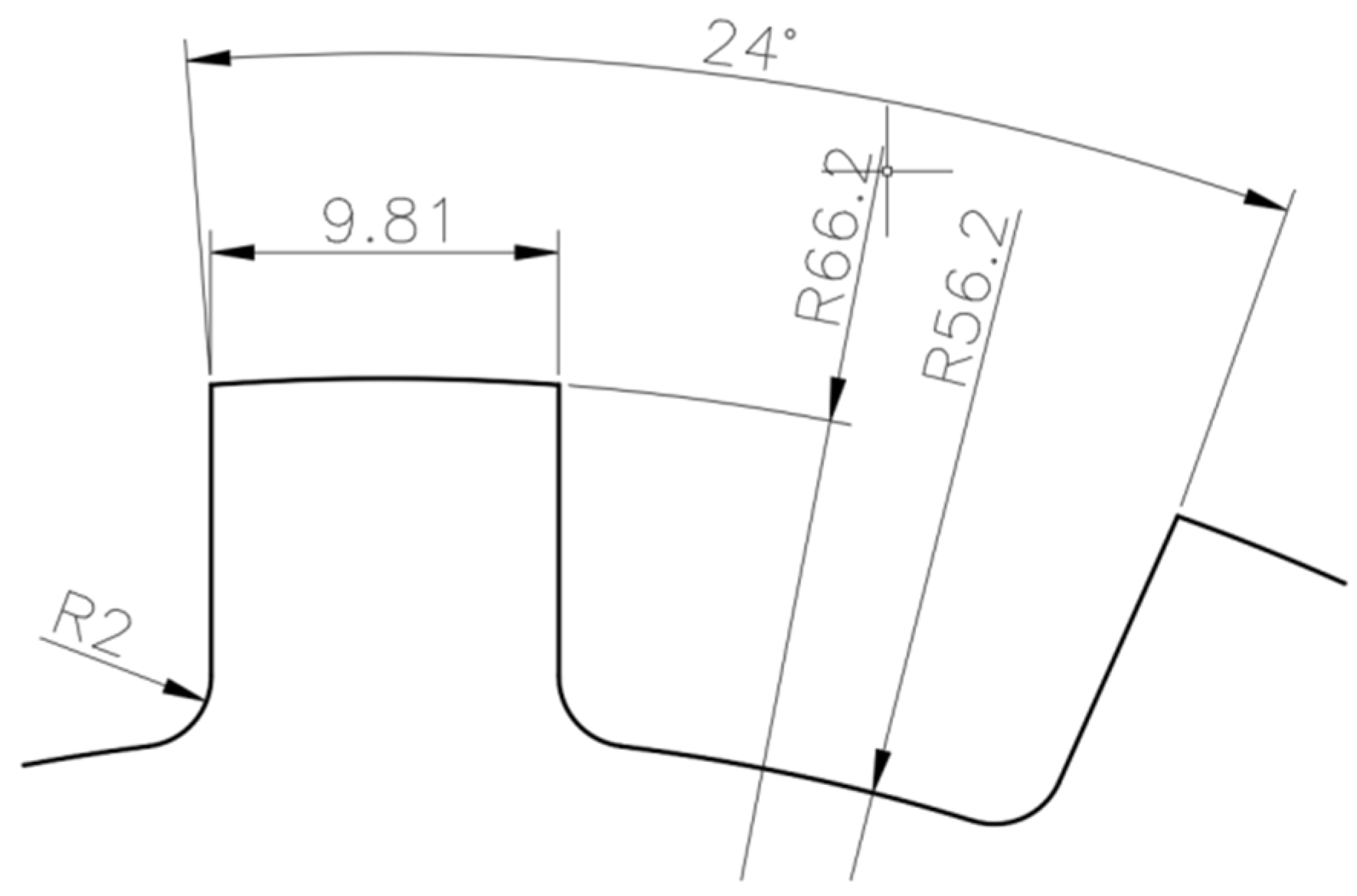
| 9.81 | 0 | 0.53 | 20.88 | 17.13 | 18.54 | 19.63 | 13.48 | 2.7 |
| No. | Rotor Tooth Dimensions | Tc [Nm] | |
|---|---|---|---|
| sz [mm] | rz [mm] | Max | |
| 1 | 7 | 0 | 0.1777 |
| 2 | 7.5 and 16.5 | 0.5 | 0.0947 |
| 3 | 8 | 1 | 0.0458 |
| 4 | 8.5 | 1.5 | 0.0659 |
| 5 | 9.5 | 2 | 0.0566 |
| 6 | 10 | 2.5 | 0.0636 |
| 7 | 11 | 3 | 0.0686 |
| 8 | 12.5 | 3.5 | 0.0551 |
| No. | Rotor Tooth Dimensions | Ts [Nm] | Te [Nm] | |
|---|---|---|---|---|
| sz [mm] | rz [mm] | Max | Avg | |
| 1 | 12.5 | 0 | 22.3956 | 18.5895 |
| 2 | 13 | 0.5 | 22.1735 | 18.5151 |
| 3 | 13.5 | 1 | 21.8866 | 18.4349 |
| 4 | 14 | 1.5 | 21.5116 | 18.3147 |
| 5 | 15 | 2 | 21.1775 | 18.1838 |
| 6 | 15.5 | 2.5 | 20.8483 | 18.0441 |
| 7 | 16.5 | 3 | 20.5114 | 17.8801 |
| 8 | 17.5 | 3.5 | 20.1541 | 17.7249 |
| No. | Rotor Tooth Dimensions | ε [%] | Rotor Tooth Dimensions | τ [%] | ||
|---|---|---|---|---|---|---|
| sz [mm] | rz [mm] | Min | sz [mm] | rz [mm] | Min | |
| 1 | 12 | 0 | 6.0634 | 7 | 0 | 0.9810 |
| 2 | 12.5 | 0.5 | 4.8921 | 7.5 | 0.5 | 0.5871 |
| 3 | 13 | 1 | 3.6321 | 8 | 1 | 0.2573 |
| 4 | 13.5 | 1.5 | 2.9448 | 8.5 | 1.5 | 0.3732 |
| 5 | 14 | 2 | 2.7315 | 9.5 | 2 | 0.3295 |
| 6 | 15 | 2.5 | 2.1374 | 10 | 2.5 | 0.3645 |
| 7 | 16 | 3 | 2.1706 | 11.5 | 3 | 0.3873 |
| 8 | 17 | 3.5 | 2.5680 | 12.5 | 3.5 | 0.3117 |
| No. | Rotor Tooth Dimensions | Tc [Nm] | Ts [Nm] | Te [Nm] | ε [%] | τ [%] | |||
|---|---|---|---|---|---|---|---|---|---|
| sz [mm] | rz [mm] | Max | Max | Min | Avg | Max | |||
| 1 | 11.7 | 0 | 0.13 | 22.03 | 17.53 | 18.06 | 18.75 | 6.78 | 0.71 |
| 2 | 11.9 | 0.5 | 0.095 | 21.86 | 17.63 | 18.12 | 18.71 | 5.89 | 0.51 |
| 3 | 12.5 | 1 | 0.072 | 21.47 | 17.45 | 17.83 | 18.22 | 4.32 | 0.39 |
| 4 | 13.1 | 1.5 | 0.073 | 21.19 | 17.38 | 17.72 | 17.97 | 3.32 | 0.41 |
| 5 | 13.2 | 1.5 | 0.076 | 21.21 | 17.37 | 17.66 | 17.91 | 3.1 | 0.43 |
| 6 | 13.3 | 1.5 | 0.079 | 21.21 | 17.35 | 17.6 | 17.84 | 2.75 | 0.45 |
| 7 | 13.8 | 2 | 0.071 | 20.92 | 17.25 | 17.56 | 17.82 | 3.28 | 0.39 |
| 8 | 14.1 | 2 | 0.091 | 20.92 | 17.17 | 17.38 | 17.55 | 2.23 | 0.52 |
| 9 | 14.5 | 2.5 | 0.075 | 20.65 | 17.03 | 17.43 | 17.72 | 3.39 | 0.42 |
| 10 | 14.7 | 2.5 | 0.076 | 20.66 | 17.00 | 17.3 | 17.55 | 3.15 | 0.43 |
| 11 | 10.3 | 2.5 | 0.053 | 18.3 | 16.89 | 17.19 | 17.67 | 4.53 | 0.3 |
| 12 | 10.4 | 2.5 | 0.06 | 18.39 | 17.05 | 17.27 | 17.72 | 3.87 | 0.34 |
| 13 | 11.2 | 3 | 0.057 | 18.4 | 16.80 | 17.14 | 17.64 | 4.84 | 0.32 |
| 14 | 11.8 | 3 | 0.074 | 18.84 | 17.15 | 17.51 | 17.87 | 4.13 | 0.42 |
| 15 | 15.3 | 3 | 0.072 | 20.4 | 16.83 | 17.24 | 17.50 | 3.91 | 0.41 |
| 16 | 15.6 | 3 | 0.076 | 20.37 | 16.77 | 17.05 | 17.28 | 2.98 | 0.44 |
| 17 | 12.2 | 3.5 | 0.051 | 18.48 | 16.81 | 17.12 | 17.60 | 4.6 | 0.29 |
| 18 | 12.8 | 3.5 | 0.053 | 18.9 | 17.05 | 17.44 | 17.77 | 4.12 | 0.3 |
| 19 | 14.7 | 3.5 | 0.066 | 19.8 | 17.09 | 17.56 | 18.19 | 6.19 | 0.36 |
| 20 | 15.7 | 3.5 | 0.073 | 20.16 | 16.69 | 17.3 | 17.72 | 5.98 | 0.41 |
| Rotor | Rotor Dimensions | Tc [Nm] | Ts [Nm] | Te [Nm] | ε [%] | τ [%] | ||
|---|---|---|---|---|---|---|---|---|
| sz [mm] | rz [mm] | δ [mm] | Max | Max | Avg | |||
| Model A | 9.81 | 0 | 0.475 | 0.53 | 20.88 | 18.54 | 13.48 | 2.7 |
| Model B | 13.3 | 1.5 | 0.475 | 0.079 | 21.21 | 17.6 | 2.75 | 0.45 |
| Model C | 13.3 | 1.5 | 0.42 | 0.083 | 23.47 | 19.24 | 3.27 | 0.43 |
Publisher’s Note: MDPI stays neutral with regard to jurisdictional claims in published maps and institutional affiliations. |
© 2022 by the authors. Licensee MDPI, Basel, Switzerland. This article is an open access article distributed under the terms and conditions of the Creative Commons Attribution (CC BY) license (https://creativecommons.org/licenses/by/4.0/).
Share and Cite
Bień, A.; Drabek, T.; Kara, D.; Kołacz, T. Reduction in the Cogging Torques in the DCEFSM Motor by Changing the Geometry of the Rotor Teeth. Energies 2022, 15, 2455. https://doi.org/10.3390/en15072455
Bień A, Drabek T, Kara D, Kołacz T. Reduction in the Cogging Torques in the DCEFSM Motor by Changing the Geometry of the Rotor Teeth. Energies. 2022; 15(7):2455. https://doi.org/10.3390/en15072455
Chicago/Turabian StyleBień, Andrzej, Tomasz Drabek, Dawid Kara, and Tomasz Kołacz. 2022. "Reduction in the Cogging Torques in the DCEFSM Motor by Changing the Geometry of the Rotor Teeth" Energies 15, no. 7: 2455. https://doi.org/10.3390/en15072455
APA StyleBień, A., Drabek, T., Kara, D., & Kołacz, T. (2022). Reduction in the Cogging Torques in the DCEFSM Motor by Changing the Geometry of the Rotor Teeth. Energies, 15(7), 2455. https://doi.org/10.3390/en15072455