Article

Effects of Heating Temperature on the Isothermal Performance of a Potassium Concentric Annular Heat Pipe

1
MOE Key Laboratory of Enhanced Heat Transfer and Energy Conservation, Beijing Key Laboratory of Heat Transfer and Energy Conversion, College of Energy and Power Engineering, Beijing University of Technology, Beijing 100124, China
2
National Institute of Metrology, Beijing 100013, China
*
Author to whom correspondence should be addressed.
Energies 2022, 15(7), 2367; https://doi.org/10.3390/en15072367
Submission received: 10 February 2022 / Revised: 7 March 2022 / Accepted: 16 March 2022 / Published: 24 March 2022

Abstract

:
For high-precision thermocouple calibration, the uniformity of the temperature field provided by the metal temperature equalizing block is low, and the structure of the gas-controlled heat pipe is complex. In order to improve the thermocouple calibration equipment, heat pipe technology can be used to provide the stability and uniformity of the temperature field of the equipment. The concentric annular heat pipe (CAHP) is completely placed in the heating furnace to provide a uniform temperature field, and limited studies consider this heating mode for alkali metal CAHPs. Specifically, no information is available on the effect of heating temperatures on the temperature distribution of the internal pipe of potassium CAHP. In this study, a temperature comparison based on potassium CAHP for high-precision thermocouple calibration was manufactured. The temperature stability and temperature uniformity of CAHP were measured, and the effects of heating temperature and heating mode on the isothermal performance in the metering wells of CAHP were studied. The CAHP can provide a very stable and uniform temperature field. Under uniform heating at 400 °C, the maximum temperature difference within 16 cm was 0.174 °C. After adjusting the heating mode, the maximum temperature difference was within 16 cm 0.095 °C. The CAHP can effectively reduce the influence of heating temperature fluctuation on the temperature in the metering well; the maximum temperature change rate of the metering wells affected by the heating furnace temperature was 0.0942 °C/°C.

1. Introduction and Literature Review

Heat pipes are a kind of heat transfer element with high efficiency and a simple structure. The working fluid absorbs a lot of heat and evaporates in the evaporator, the vapor flows to the condenser by pressure difference and the heat is released by vapor condensation [1]. Now heat pipes are used in solar energy heat utilization [2,3], electronic component cooling [4,5], reactor cooling [6,7] and other applications that need to transfer a large amount of heat flux. Due to the vapor working fluid being saturated when the heat pipe operates stably, the change of working fluid pressure is very small, and the change of working fluid temperature is very small. Therefore, the heat pipe also has good isothermal performance. Boo et al. [8] studied the effect of the wick structure of isothermal performance. Two sodium heat pipes with the same shape and different wicks were experimentally studied. The wick structure could make the distribution of liquid working fluid more uniform, and the lowest temperature difference was 151 °C. Hack et al. [9] studied the effect of the working fluid charge ratio on isothermal performance. Ceramic heat pipes with different working fluid charge ratios were experimentally studied. When the working fluid was charged with 100 g, which was 11% of the total internal volume, the heat pipe achieved the best isothermal performance. Therefore, heat pipes are also used to obtain uniform temperature fields, such as isothermal reactors applications [10,11], thermal management applications [12,13], calibration applications [14,15], etc.
For the cylindrical heat pipes, the axial uniform temperature field can only be formed on the condenser wall. For flat plate heat pipes, a uniform temperature field can be formed on the condenser surface. However, for the concentric annular heat pipes (CAHPs), a uniform temperature space can be formed in the inner pipe. CAHPs are a kind of heat pipe composed of two concentric pipes; the working fluid flows in the space between the two pipes. Figure 1 present the structure of CAHPs. Zhao et al. [16] studied the heat transfer performance of high-temperature CAHPs under different heating angles. The heating method was the same for the cylindrical heat pipe, the evaporator was at one end of the CAHP, and the condenser was at the other end of the CAHP. Because the wick on the inner pipe provided additional capillary force, the CAHP can also be started under anti gravity conditions. Under different inclination angles, the thermal resistance of CAHP was less than 0.05 °C/W. Boo et al. [17] studied the thermal performance of CAHPs. Three bridge wicks were designed to reflux liquid working fluid. The maximum axial temperature difference on the outer surface of CAHP was 2.3 °C, and the minimum thermal resistance was 0.04 °C/W under 180 W heating. Mustaffar et al. [18] studied the characterization of a CAHP in a drying application. In this application, the whole inner pipe was used as a condenser, and the part of the outer pipe was used as an evaporator. The effects of working fluid filling ratio, the inclination of CAHP and heating power on the temperature distribution of the condenser were studied. The axial temperature difference of CAHP was the smallest when the working fluid filling ratio was 11%. This drying application can reduce the moisture content by 12% under 302 W heating.
In the field of measurement, because of the high requirement of high precision, CAHPs are often used as isothermal furnaces. Usually, the outer pipes of CAHPs are used as evaporators to heat at a constant temperature, and the inner pipes are used as condensers to provide a stable and uniform temperature field. Choi et al. [19] manufactured and texted a naphthalene heat pipe furnace. The start-up performance and thermal performance were experimentally studied. The inner part of the inner pipe was used as the condenser, and the lower part of the outer pipe was used as the evaporator. The maximum temperature difference in the isothermal zone of CAHP was 1 °C under 200 °C to 300 °C heating temperature. Sanchez et al. [20] studied the effects of heating power and cooling water flow rate on temperature distribution in a water CAHP. This CAHP could provide a 21 cm long region with a high isothermal property when heated at 350 W. Gam et al. [21] manufactured a sodium CAHP furnace to study the measurement accuracy of the precious metal thermocouple. The sodium CAHP furnace can work from 660 °C to 962 °C, and the maximum temperature difference is 35 mK. Yan et al. [22] designed and manufactured a sodium CAHP, and the CAHP was used as a liner of isothermal furnaces to reduce the influence of the environment and heating furnace on the temperature field. When the CAHP is working with the aluminum point cell, a temperature field with a maximum temperature difference of less than 15 mK could be provided.
In order to obtain a more stable and uniform temperature field, gas-controlled heat pipes (GCHPs) were used. Because the working fluid vapor is saturated when the heat pipe operates stably, the temperature difference of the working fluid changes with the pressure difference. In GCHPs, the inert gas is introduced into the heat pipe, the pressure of the inert gas is controlled through the pressure control system. Therefore, the pressure and temperature of the working fluid vapor in the heat pipe can be controlled. Merlone et al. [23] designed and manufactured a mercury GCHP. Due to the PID control of the pressure control system, a 10 cm long uniform temperature zone can provide different heating temperatures. The maximum temperature difference of the GCHP was less than 1 mK at 235 °C to 450 °C. Yan et al. [24] manufactured a sodium GCHP. When the pressure control system controlled the working fluid pressure at 111250 Pa, the temperature stability in GCHP was better than ±0.25 mK, the maximum temperature difference in 14 cm was less than 0.3 mK.
Although GCHPs can provide a temperature field with very high stability and uniformity, GCHPs require a very complex and expensive pressure control system [25]. For the calibration of high-precision thermocouples such as Au/Pt type [26,27], equipment with a simple structure and high-precision calibration is required. Here, the dry type metering furnace used a metal temperature equalizing block to provide a temperature field. The maximum temperature difference within 4 cm was 0.1 °C, and the heat pipe technology can be used to improve the metal temperature equalizing block.
Because the boiling point of alkali metal is high and the saturated steam pressure is low, the alkali metal is suitable for the working medium of the high-temperature heat pipe. Sodium and potassium are commonly used working fluids for high-temperature heat pipes. The working temperature range of potassium is 400 °C to 1000 °C [15], which is larger than that of sodium, and the temperature range is more suitable for calibrating high-temperature thermocouples. In the field of metrology, the heating mode of the heat pipe is relatively special. The CAHP is completely placed in the heating furnace to provide a uniform temperature field, and limited studies consider this heating mode for alkali metal CAHPs. Specifically, no information is available on the effect of heating temperatures on the temperature distribution of the internal pipe of potassium CAHP. In this study, a temperature comparison based on potassium CAHP for high-precision thermocouple calibration was manufactured. The potassium CAHP had a bridge wick between the inner pipe and outer pipe so that the heat pipe also had high-temperature uniformity when it was placed horizontally. The temperature stability and temperature uniformity of CAHP were measured, and the effects of heating temperature and heating mode on the isothermal performance in the metering wells of CAHP were studied.

2. Experimental Methods

2.1. Experimental System and Procedure
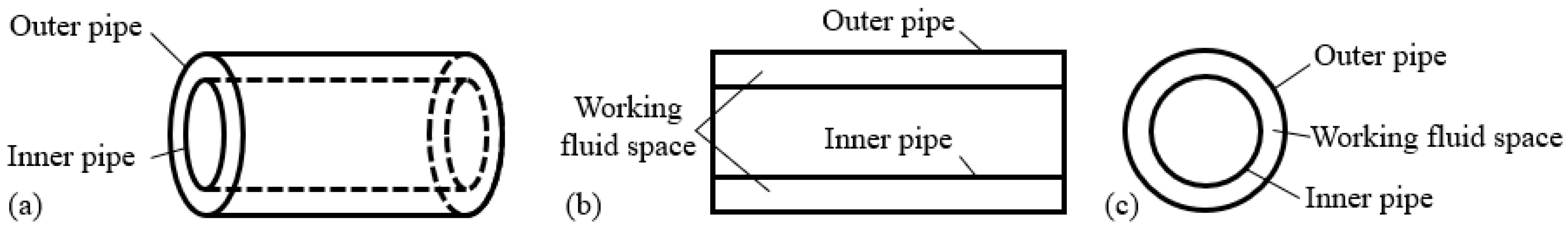
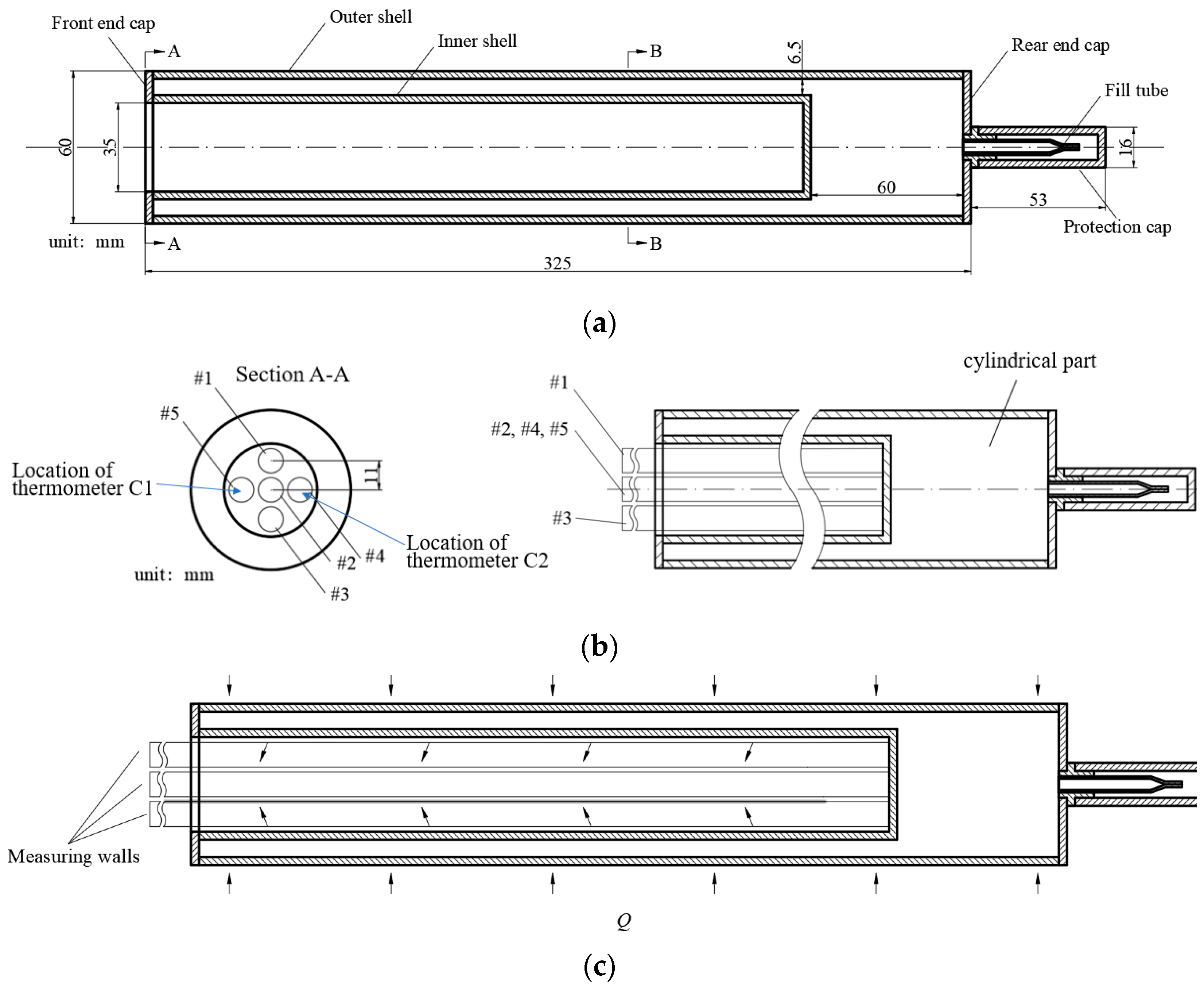
Figure 2 present the experimental system. A potassium CAHP was placed horizontally and heated in a three-stage temperature-controlled heating furnace to provide a uniform temperature field under different heating temperatures and temperature control modes. Two standard platinum resistance thermometers (SPRTs) were used to measure the temperature distribution in the metering well in the inner pipe of CAHP. In this study, the CAHP was heated at a constant temperature of 400 °C, 500 °C and 600 °C, and the temperature in the metering wells was measured.
In Section 3.1, to study the influence of heating mode on the temperature distribution in CAHP metering wells, the heating temperature of the left and right sections were adjusted to obtain the best temperature uniformity at 400 °C, the temperature at 0 cm, 2 cm, 4 cm, 6 cm, 8 cm, 10 cm, 12 cm, 14 cm and 16 cm from the bottom of the metering well was measured. In the experiment, one thermometer as a reference thermometer was always placed at the bottom of the metering well, and the other as a measuring thermometer to measure the temperature at different positions. In the beginning, both thermometers were placed at the bottom of the metering well. After the temperature was stable, the measuring thermometer was pulled out by 2 cm. The temperature was measured at 2 cm after the temperature was stable, and then the measuring thermometer was pulled out to continue the measurement.
In Section 3.2, to study the influence of the temperature fluctuation of the heating furnace on the bottom temperature of the metering well, the heating temperature of the right section was reduced from 400 °C, 500 °C and 600 °C, and the reduction of the heating temperature of the right heating section was 0 °C, 1 °C, 2 °C and 3 °C, respectively. Table 1 show the heating temperatures in different cases. The measuring position was at the bottom of the metering well. The temperature change at the bottom of the metering well was measured.
In Section 3.2, to study the influence of heating temperature fluctuation on the temperature distribution in the metering well, the heating temperature was the same as Case 2 in Table 1, and the measuring points were 0 cm, 2 cm, 4 cm, 6 cm and 8 cm away from the bottom of the metering well, respectively.

2.2. Potassium CAHP

Figure 3 present the structure and size of potassium CAHP. The size and structure of CAHP referred to the metal temperature equalizing block. Since the length of the outer shell was 60 mm longer than that of the inner shell, a cylindrical part was formed at the bottom of the CAHP. The cylindrical part can fill the working fluid at the bottom of CAHP and improve the isothermal performance in the inner tube. Sodium and potassium are commonly used working fluids for high-temperature heat pipes. The working temperature range of potassium is 400 °C to 1000 °C [15], which is larger than that of sodium, and the temperature range is more suitable for calibrating high-temperature thermocouples. Therefore, potassium was chosen as the working fluid. The working fluid used 100 g metal potassium with purity of 99.95%, and the volume of the working fluid was 28.7% of the internal volume. The CAHP was placed horizontally, and the height of the liquid level can be calculated as 14 mm. Table 2 present the properties of potassium.
Figure 3b present the position of metering wells; the cross-section was section A-A in Figure 3a. The 9.5 mm diameter quartz tubes were used as a metering well to support the thermometers, five metering wells were set in the CAHP inner pipe. The distance between the middle metering well and other metering wells was 11 mm. In this study, thermometer C1 was always placed in the left metering well (#5), and thermometer C2 was always placed in the right metering well (#4).
Figure 3c present the working mode and heat flow direction of CAHP. Unlike other heat pipes for heat transfer, the CAHP was used to provide a temperature field with high stability and uniformity. In this study, the whole CAHP was placed horizontally in the heating furnace and heated at a constant heating temperature. The working fluid evaporated on the outer pipe wall and condensed on the inner pipe wall; the heat was transmitted from the metering wells and thermometers.
There were six double-layer 80 mesh wicks between the inner pipe and the outer pipe to make the liquid working fluid return to the evaporation side stably.

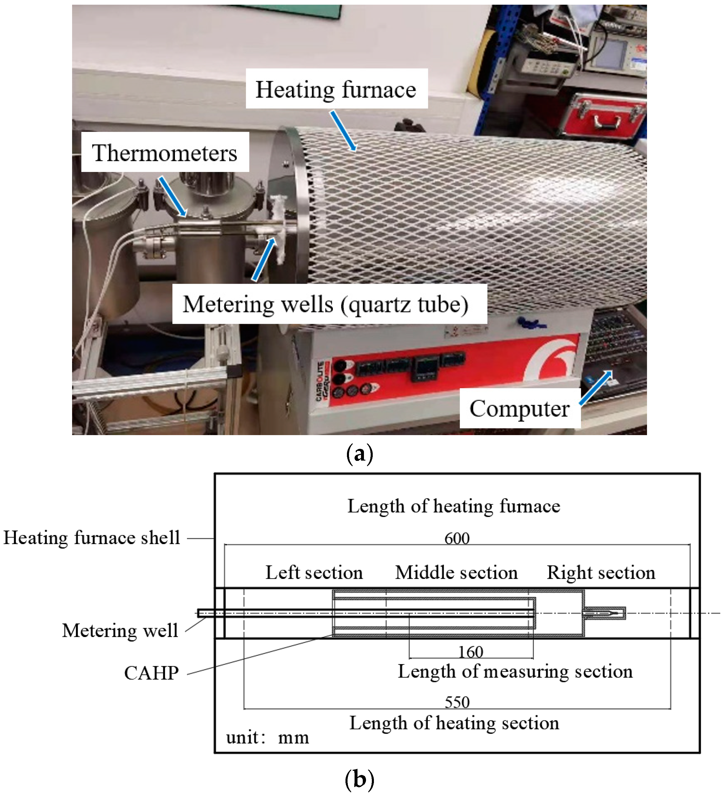
2.3. Heating Furnace

A three-section heating furnace was used, the heating range was 20 °C to 1000 °C, the temperature control accuracy of the heating furnace was ±0.5 °C, and the furnace provided a temperature field with a maximum temperature difference of 5 °C within 390 mm of the middle area. The heating furnace has three independent heating systems, and the heating temperature of each section can be set separately. The temperature measuring points of the heating furnace temperature are in the middle of the heating section. The outer pipe of CAHP was placed in the center of the heating furnace. Figure 2b present the size and structure of the three-section heating furnace. The CAHP was heated at a constant temperature of 400 °C, 500 °C and 600 °C. The temperature distribution within 0 cm to 16 cm from the bottom of the metering well was measured, and the measurement area was in the middle section of the heating furnace.
The temperature in the metering wells was measured by two SPRTs, which were calibrated by the National Institute of Metrology, and the temperature measurement accuracy was 0.5 mK.

2.4. Temperature Stability and Reproducibility

In the experiment, SPRTs were used for temperature measurement. SPRTs were calibrated by the National Institute of metrology, and the temperature measurement accuracy was 0.5 mK. Figure 4 present the temperature stability and experimental reproducibility of potassium CAHP in this study. Case 1 and Case 2 were two experiments with the same heating condition and measuring method on two different days. The temperature fluctuation in the metering wells after 250 min was less than ±0.005 °C. Comparing the two experiments, the measurement showed that the experiments had good reproducibility, and the temperature difference was less than 1%.

3. Results and Discussions

3.1. Effect of Heating Mode on Isothermal Performance of CAHP

Figure 5a present the whole process of this group of experiments. Because the heating furnace was not completely cooled down after the experiment of the previous day, the temperature of the metering well was about 70 °C at 0 min. The furnace temperature rise rate was set as 4 °C/min from 0 to 40 min, and 8 °C/min from 40 to 70 min and the temperature of the measuring point increased at the same rate as the furnace temperature. Figure 5b present the measurement process of temperature distribution in the right metering well (#4) under 400 °C heating; the heat pipe temperature was higher than the set temperature in the experiment and was caused by the uneven heating temperature of the heating furnace. The heating temperature of the three-stage heating furnace was set to 400 °C-400 °C-400 °C, and the temperature was measured from the bottom of the metering well by thermometer C2. When the temperature was stable, the thermometer was pulled out for 2 cm to measure the temperature at the next position. Figure 5c present the temperature distribution of the right metering well (#4) under 400 °C-400 °C-400 °C heating. It can be seen that the temperature near the bottom and 16 cm of the metering well was higher. Because the heat flowed out from the metering well, the temperature at the bottom of the metering well was higher. Due to the temperature compensation of the heating furnace at the outlet of the metering well, the temperature at 16 cm of the metering well was also higher.
Since the heating furnace can set three different heating temperatures in the horizontal direction, changing the heating temperature in different areas of the heating furnace can change the temperature distribution in the metering wells.
Figure 6a present the influence of left heating temperature on temperature distribution in the metering well. As shown in Figure 2, the metering well of CAHP was placed to the left, and the temperature of the left section of the heating furnace mainly affects the part away from the bottom of the metering well. As the temperature in the left section decreased, the temperature at 8 cm to 16 cm decreased obviously. When the temperature of the left section was 395 °C, the temperature at 16 cm was greatly reduced, so it was not marked in Figure 6a.
Figure 6b present the influence of the right heating temperature on the temperature distribution in the metering well. Since the cylindrical part was in the right section and there was more working fluid vapor, the temperature in the right section had a smaller effect on the temperature in the metering well.
Figure 6c present the influence of left and right heating temperature on temperature distribution in the metering well. From Figure 6a, the temperature of the left section had a great influence on the temperature away from the bottom of the metering well. Therefore, the left section temperature was set to 396 °C. From Figure 6b, the temperature of the right section had little effect on the bottom temperature of the metering well, so the temperature of the right section was adjusted greatly. The maximum temperature difference within 0 cm to 16 cm was 0.174 °C under 400 °C-400 °C-400 °C heating. After compensation by adjusting the heating temperature of the heating furnace, the maximum temperature difference in the metering well was 0.095 °C under 396 °C-400 °C-392 °C heating.

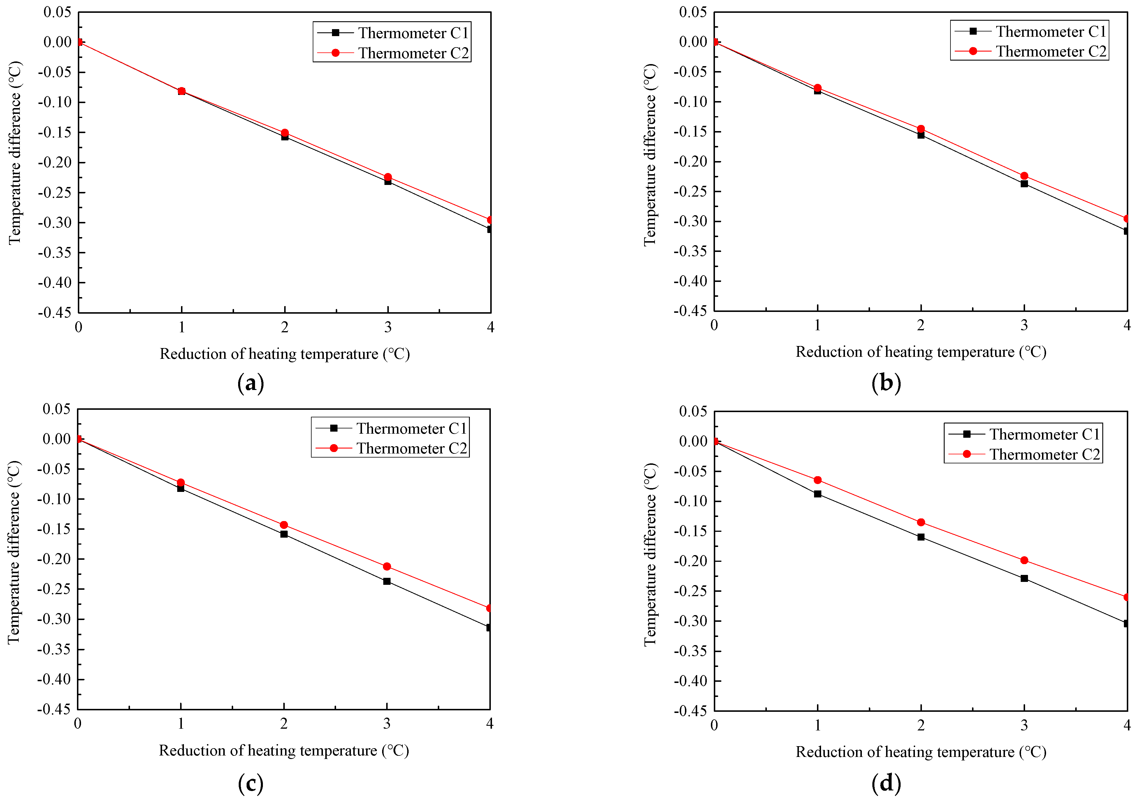
3.2. Influence of Temperature Fluctuation under Different Heating Temperature

The temperature fluctuation of the heating furnace and ambient will lead to the temperature fluctuation in the metering well. Therefore, understanding the influence of heating temperature fluctuation on the temperature in the metering well is very important to calibrate the high-temperature thermocouple. As the temperature of the right section of the heating furnace decreased gradually, the temperature at the bottom of the metering well was measured.
Figure 7 present temperature change in the metering well when the temperature of the heating furnace changes. Figure 7a present the measurement process. Due to the temperature at the bottom of the metering well being more stable, the thermometers were placed at the bottom of the metering well, the heating temperature of the right section decreased gradually, and the temperature changed at the bottom of the metering wells were measured.
The temperature control point of the right section heating system was located in the middle of the right section and about 80 cm away from the bottom of the metering well.
Figure 7b to Figure 7d present the temperature difference with the reduction of heating temperature under 400 °C to 600 °C heating. As the heating temperature decreased, the temperature in the metering well decreased linearly, and the temperature changes in the left and right metering wells (#5 and #4) were the same.
Figure 8 compare the temperature difference with the reduction of heating temperature of the right metering well (#4) under different heating temperatures. Table 3 present the temperature change rate of the right metering well (#4) under different heating temperatures. When the heating temperature was 600 °C, the temperature change rate was 0.0705 °C/°C; this means that the temperature of the heating furnace changes by 1 °C and the temperature at the bottom of the metering well changed by 0.0705 °C. It can be seen that, with the increase of heating temperature, the phase transition of working fluid was more intense and the internal temperature of CAHP was more stable. Due to the phase change and flow of working fluid, the CAHP can reduce the influence of heating temperature fluctuation on the temperature in the metering well.

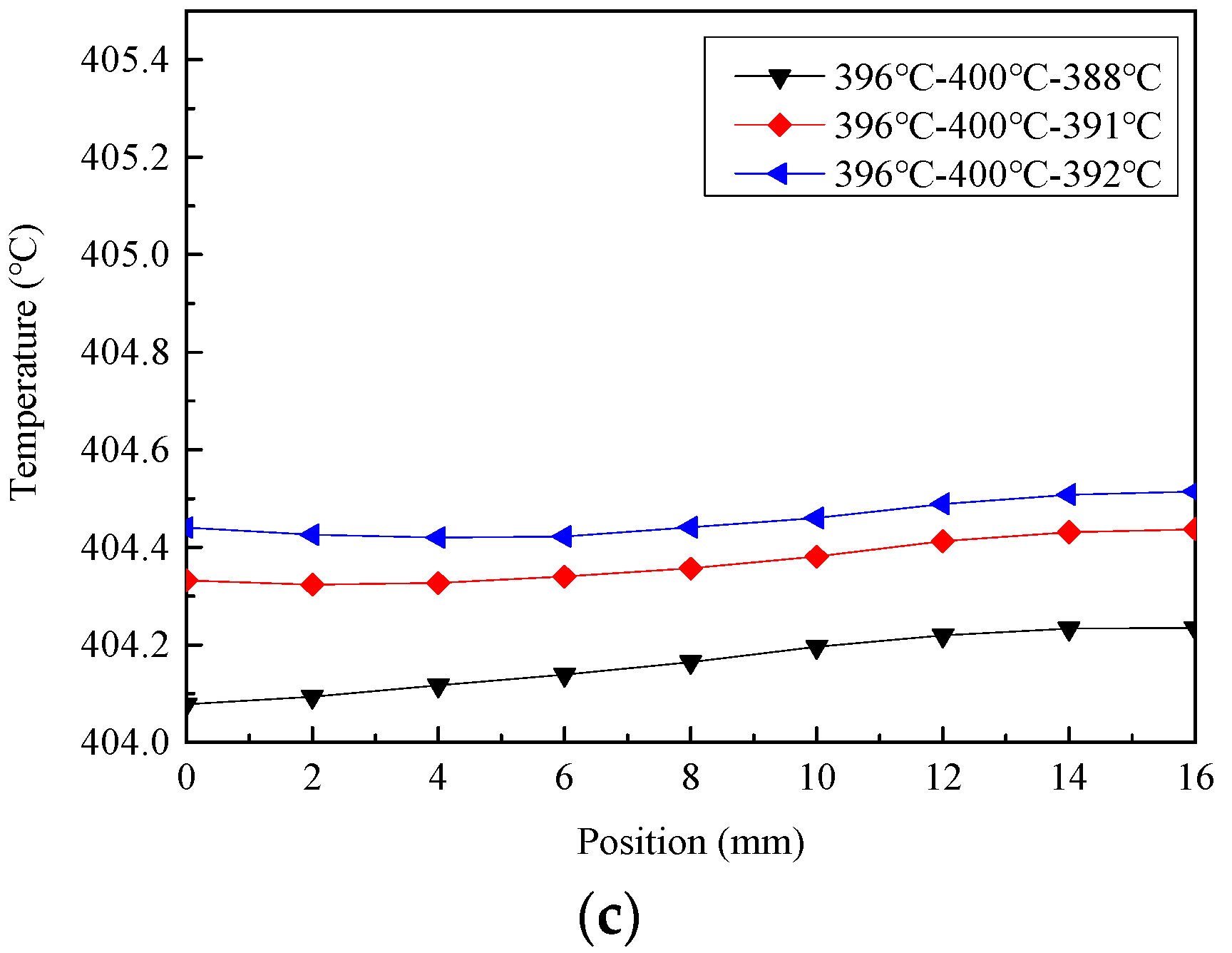
3.3. Influence of Heating Temperature Fluctuation on Temperature Distribution

Because the heat pipe had a strong heat transfer capacity, the temperature in the metering well was also affected at a location far from the temperature fluctuation point of the heating furnace. As the temperature of the right section of the heating furnace decreased gradually, the temperature at different positions of the metering well was measured.
The heating temperature of the left and middle sections were always 500 °C, the heating temperature of the right section was 500 °C to 496 °C. The temperature change within 8 cm from the bottom of the metering well was measured. Figure 9 present the temperature difference with the reduction of heating temperature at different positions under 500 °C heating temperature. Thermometer C1 was always placed at the bottom of the metering well, and thermometer C2 was placed at 2 cm to 8 cm away from the bottom of the metering well to measure the temperature change. As the measuring position was far away from the right heating section, the temperature change in the metering well decreased.
Due to the volume of the thermometer in the metering well being different when the thermometer C2 measured different positions, it may affect the measurement accuracy. Figure 10 present the temperature change at the bottom of the metering well when the thermometer C2 measured different positions. It can be seen that the temperature change was basically the same when measuring 0 cm to 6 cm; the thermometer had little impact on the measurement. The temperature change rate decreased slightly when measuring at 8 cm. At this position, the longer part of the thermometer was in the air, and there was also more air in the metering well, which had a certain impact on the temperature in the metering well. Table 4 present the temperature change rate of the right metering well (#4) at 0 cm to 8 cm under 500 °C. Due to the phase change and flow of working fluid, the CAHP made the temperature change smoother, and there was a small difference in temperature change rate from 0 cm to 8 cm from the bottom of the metering well.

4. Conclusions

A temperature comparison source based on potassium concentric annular heat pipe was developed for high-precision thermocouple calibration. The working temperature range of potassium is 400 °C to 1000 °C [15], which is larger than that of sodium, and the temperature range is more suitable for calibrating high-temperature thermocouples. The temperature stability and temperature uniformity within 0 cm to 16 cm of the different metering wells and temperature change rate at different heating temperatures and positions were experimentally studied. The main conclusions were as follows:
(1) The concentric annular heat pipe can provide a very stable and uniform temperature field. Under uniform heating at 400 °C, the maximum temperature difference within 16 cm was 0.174 °C. After adjusting the heating mode, the maximum temperature difference was 0.095 °C.
(2) The cylindrical part is not sensitive to the change of heating temperature, and the temperature near the bottom of the metering well is more stable and uniform.
(3) The concentric annular heat pipe can reduce the influence of heating temperature fluctuation on the temperature in the metering well.
(4) The concentric annular heat pipe can make the temperature change smoother, and there was a small difference in temperature change rate from 0 cm to 8 cm from the bottom of the metering well.

Author Contributions

Conceptualization, H.Z. and H.G.; data curation, H.Z.; formal analysis, H.Z.; funding acquisition, F.Y. and X.Y.; investigation, H.Z.; methodology, H.Z.; project administration, F.Y. and X.Y.; resources, F.Y. and X.Y.; supervision, H.G. and F.Y.; visualization, H.Z.; writing—original draft, H.Z.; writing—review and editing, H.G. and F.Y. All authors listed have made a substantial, direct, and intellectual contribution to the work. All authors have read and agreed to the published version of the manuscript.

Funding

This work was funded by the National Key R&D Program of China [grant number 2017YFF0205901].

Institutional Review Board Statement

Not applicable.

Informed Consent Statement

Not applicable.

Data Availability Statement

The supporting data will be made available on request.

Conflicts of Interest

The authors declare that they have no conflict of interest.

References

  1. Cotter, T.P. Theory of Heat Pipes; Los Alamos Scientific Laboratory: Los Alamos, NM, USA, 1965. [Google Scholar]
  2. Boo, J.H.; Kim, S.M.; Kang, Y.H. An experimental study on a sodium loop-type heat pipe for thermal transport from a high-temperature solar receiver. Energy Procedia 2015, 69, 608–617. [Google Scholar] [CrossRef] [Green Version]
  3. Coventry, J.; Andraka, C.; Pye, J.; Blanco, M.; Fisher, J. A review of sodium receiver technologies for central receiver solar power plants. Solar Energy 2015, 122, 749–762. [Google Scholar] [CrossRef] [Green Version]
  4. McGlen, R.J.; Jachuck, R.; Lin, S. Integrated thermal management techniques for high power electronic devices. Appl. Therm. Eng. 2004, 24, 1143–1156. [Google Scholar] [CrossRef]
  5. Boukhanouf, R.; Haddad, A.; North, M.T.; Buffone, C. Experimental investigation of a flat heat pipe performance using IR thermal imaging camera. Appl. Therm. Eng. 2006, 26, 2148–2156. [Google Scholar] [CrossRef]
  6. Mukhsinun, H.K.; Nandy, P.; Anhar, R.A.; Raldi, A.K.; Surip, W.; Sri, I.; Brilian, T.V. Passive cooling system in a nuclear spent fuel pool using a vertical straight wickless-heat pipe. Int. J. Therm. Sci. 2018, 126, 162–171. [Google Scholar]
  7. Liu, M.H.; Zhang, D.L.; Wang, C.L.; Qiu, S.Z.; Su, G.H.; Tian, W.X. Experimental study on heat transfer performance between fluoride salt and heat pipes in the new conceptual passive residual heat removal system of molten salt reactor. Nucl. Eng. Des. 2018, 339, 215–224. [Google Scholar] [CrossRef]
  8. Boo, J.H.; Park, S.Y. Isothermal characteristics of a rectangular parallelepiped sodium heat pipe. J. Mech. Sci. Technol. 2005, 19, 1044–1051. [Google Scholar] [CrossRef]
  9. Hack, N.; Unz, S.; Beckmann, M. Ceramic heat pipes for high temperature application. In Proceedings of the INFUB-11th European Conference on Industrial Furnaces and Boiler, Algarve, Portugal, 18–21 April 2017; pp. 140–148. [Google Scholar]
  10. Diver, R.B.; Fish, J.D.; Levitan, R.; Levy, M.; Meirovitch, E.; Rosin, H.; Paripatyadar, S.A.; Richardson, J.T. Solar test of an integrated sodium reflux heat pipe receiver/reactor for thermochemical energy transport. Sol. Energy 1992, 48, 21–30. [Google Scholar] [CrossRef]
  11. Ahmad, M.; Adam, H.; David, R. Melting of phase change material assisted by expanded metal mesh. Appl. Therm. Eng. 2015, 90, 1052–1060. [Google Scholar]
  12. Vadiraj, A.H.; Ashish, G.; Sameer, K. Thermal radiators with embedded pulsating heat pipes: Infra-red thermography and simulations. Appl. Therm. Eng. 2011, 31, 1332–1346. [Google Scholar]
  13. Reyes, M.; Alonso, D.; Arias, J.R.; Velazquez, A. Experimental and theoretical study of a vapor chamber based heat spreader for avionics applications. Appl. Therm. Eng. 2012, 37, 51–59. [Google Scholar] [CrossRef]
  14. Tamba, J.; Yamazawa, K.; Masuyama, S.; Ogura, H.; Izuchi, M. Evaluating the inhomogeneity of thermocouples using a pressure-controlled water heat pipe. Int. J. Thermophys. 2011, 32, 2436–2451. [Google Scholar] [CrossRef]
  15. Bertiglia, F.; Iacomini, L.; Moro, F.; Merlone, A. Comparison of two potassium-filled gas-controlled heat pipes. Int. J. Thermophys. 2015, 36, 3393–3403. [Google Scholar] [CrossRef]
  16. Zhao, J.; Yuana, D.Z.; Tang, D.W.; Jiang, Y.Y. Heat transfer characteristics of a concentric annular high temperature heat pipe under anti-gravity conditions. Appl. Therm. Eng. 2019, 148, 817–824. [Google Scholar] [CrossRef]
  17. Boo, J.H.; Park, S.Y. An experimental study on the thermal performance of a concentric annular heat pipe. J. Mech. Sci. Technol. 2005, 19, 1036–1043. [Google Scholar] [CrossRef]
  18. Mustaffar, A.; Phan, A.N.; Reay, D.; Boodhoo, K. Concentric annular heat pipe characterisation analysis for a drying application. Appl. Therm. Eng. 2019, 149, 275–286. [Google Scholar] [CrossRef]
  19. Choi, J.; Yuan, Y.; Borca-Tasciuc, D.A.; Kang, H. Design, construction and performance testing of an isothermal naphthalene heat pipe furnace. Rev. Sci. Instrum. 2014, 85, 95–105. [Google Scholar] [CrossRef]
  20. Sanchez, F.S.; Carvajal, I.M.; Morino, A.E.; Diez, P.Q.; Velazquez, M.T. Study of an annular two-phase thermosyphon used as an isothermal source in thermometry. J. Mech. Eng. 2015, 61, 273–282. [Google Scholar] [CrossRef]
  21. Gam, K.S. A stable microcomputer-controlled heat pipe furnace and test of new noble metal thermocouples. Measurement 1996, 18, 101–108. [Google Scholar] [CrossRef]
  22. Yan, X.K.; Duan, Y.N.; Ma, C.F.; Lv, Z.F. Construction of sodium heat-pipe furnaces and the isothermal characteristics of the furnaces. Int. J. Thermophys. 2011, 32, 494–504. [Google Scholar] [CrossRef]
  23. Merlone, A.; Giunta, S.; Tiziani, A. A new mercury gas-controlled heat pipe for temperature amplifier and as calibration facility. Int. J. Thermophys. 2008, 29, 1876–1886. [Google Scholar] [CrossRef]
  24. Yan, X.; Zhang, J.T.; Merlone, A.; Duan, Y.; Wang, W. NIM gas controlled sodium heat pipe. In Proceedings of the 9th International Temperature Symposium on Temperature—Its Measurement and Control in Science and Industry, Los Angeles, CA, USA, 19–23 March 2012; pp. 834–839. [Google Scholar]
  25. Giunta, S.; Merlone, A.; Marenco, S.; Marcarino, P.; Tiziani, A. Capabilities of a new pressure controller for gas-controlled heat pipes. Int. J. Thermophys. 2008, 29, 1887–1895. [Google Scholar] [CrossRef]
  26. Jahan, F.; Ballico, M.J. Calibration of radiation thermometry fixed points using Au/Pt thermocouples. Int. J. Thermophys. 2011, 32, 361–371. [Google Scholar] [CrossRef]
  27. Zhao, G.C.; Zhao, C.L.; Song, L.P.; Tong, X.Y. Research on and applications of Au/Pt thermocouples. Appl. Mech. Mater. 2014, 483, 105–109. [Google Scholar] [CrossRef]
Figure 1. Structure of concentric annular heat pipes: (a) Three-dimensional structure; (b) Longitudinal section; (c) Transverse section.
Energies 15 02367 g001
Figure 2. Experimental equipment: (a) Photo of experimental equipment; (b) Size and structure of three-section heating furnace.
Energies 15 02367 g002
Figure 3. Potassium CAHP structure: (a) CAHP size; (b) Metering wells; (c) Direction of heat flow during operation; (d) Photo of metering well.
Energies 15 02367 g003aEnergies 15 02367 g003b
Figure 4. Experimental reproducibility of potassium CAHP under 400 °C.
Energies 15 02367 g004
Figure 5. Measurement process of axial temperature distribution in right metering well (#4) under 400 °C-400 °C-400 °C heating: (a) Whole measurement process; (b) Measurement process of thermometer C2; (c) Temperature distribution of right metering well (#4).
Energies 15 02367 g005
Figure 6. Temperature distribution in metering well under different temperature settings: (a) Only adjust the temperature of left section; (b) Only adjust the temperature of right section; (c) Adjust the temperature of left and right sections.
Energies 15 02367 g006aEnergies 15 02367 g006b
Figure 7. Temperature difference with reduction of heating temperature under different heating temperature at the bottom of metering well: (a) Measurement process under 400 °C heating temperature; (b) temperature difference under 400 °C; (c) temperature difference under 500 °C; (d) temperature difference under 600 °C.
Energies 15 02367 g007
Figure 8. Comparison of temperature difference with reduction of heating temperature of right metering well (#4) under different heating temperatures.
Energies 15 02367 g008
Figure 9. Temperature difference with reduction of heating temperature at different position under 500 °C heating temperature: (a) At 2 cm; (b) At 4 cm; (c) At 6 cm; (d) At 8 cm.
Energies 15 02367 g009
Figure 10. Comparison of temperature difference with reduction of heating temperature at different positions under 500 °C heating temperature: (a) Temperature difference of left metering well (#5); (b) Temperature difference of right metering well (#4).
Energies 15 02367 g010
Table 1. Heating temperature in the study of the influence of temperature fluctuation.
Case 1Case 2Case 3
400 °C-400 °C-400 °C500 °C-500 °C-500 °C600 °C-600 °C-600 °C
400 °C-400 °C-399 °C500 °C-500 °C-499 °C600 °C-600 °C-599 °C
400 °C-400 °C-398 °C500 °C-500 °C-498 °C600 °C-600 °C-598 °C
400 °C-400 °C-397 °C500 °C-500 °C-497 °C600 °C-600 °C-597 °C
Table 2. Thermal properties of potassium.
PropertiesValues
Boiling temperature (0.1 MPa)756.5 °C
Density (500 °C)726.7 kg/m3
Specific heat (500 °C)0.77 kJ/(kg·K)
Viscosity (500 °C)1.5 × 10⁻³ Pa·s
Latent heat of vaporization (0.1 MPa)1983.7 kJ/kg
Table 3. Temperature change rate of right metering well (#4) under different heating temperatures.
Heating TemperatureTemperature Change Rate
400 °C0.0942 °C/°C
500 °C0.0790 °C/°C
600 °C0.0705 °C/°C
Table 4. Temperature change rate of right metering well (#4) at 0 cm to 8 cm under 500 °C.
PositionTemperature Change Rate
0 cm0.0790 °C/°C
2 cm0.0764 °C/°C
4 cm0.0739 °C/°C
6 cm0.0705 °C/°C
8 cm0.0650 °C/°C
Publisher’s Note: MDPI stays neutral with regard to jurisdictional claims in published maps and institutional affiliations.

