
The Use of Equipment for the Study of Phase Changes to Determine the Conditions of Precipitation of Inorganic Sediments in Geothermal Waters

 , , , and
Abstract
:
1. Introduction
- Hydrothermal energy, where the energy is stored in groundwater, and is extracted in the form of water, steam or water-steam mixtures;
- Petrothermal, where the energy is stored in dry, heated porous rocks or salt domes, and is acquired by injection of media (gas or water) from the surface to the geothermal reservoir.
1.1. Geothermal Energy in Poland
- “Geology and mining. (Part 1) Getting to know the geological structure of the country and the management of mineral and groundwater resources”.
- “Polish Geotermia Plus”.
- “Providing access to thermal waters in Poland” [10].
1.2. Problems Related to the Use of Geothermal Waters
2. Materials and Methods
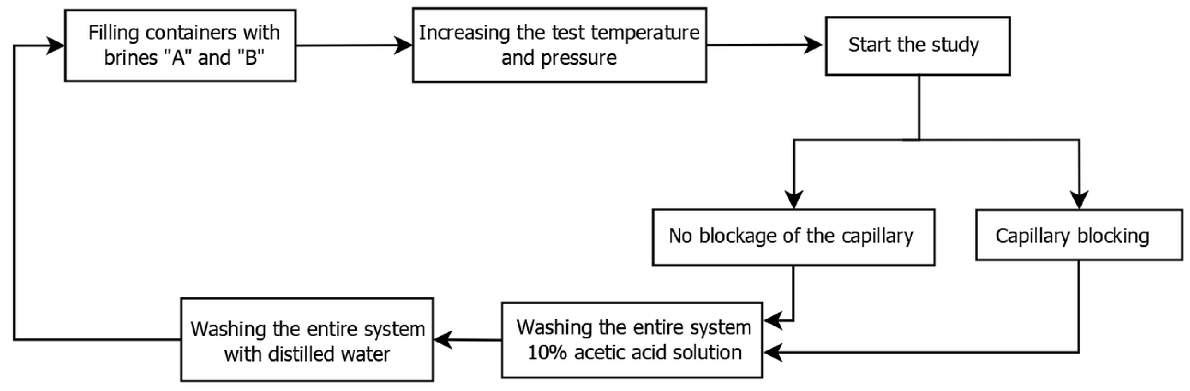
2.1. Tube Blocking Tests (TBT)
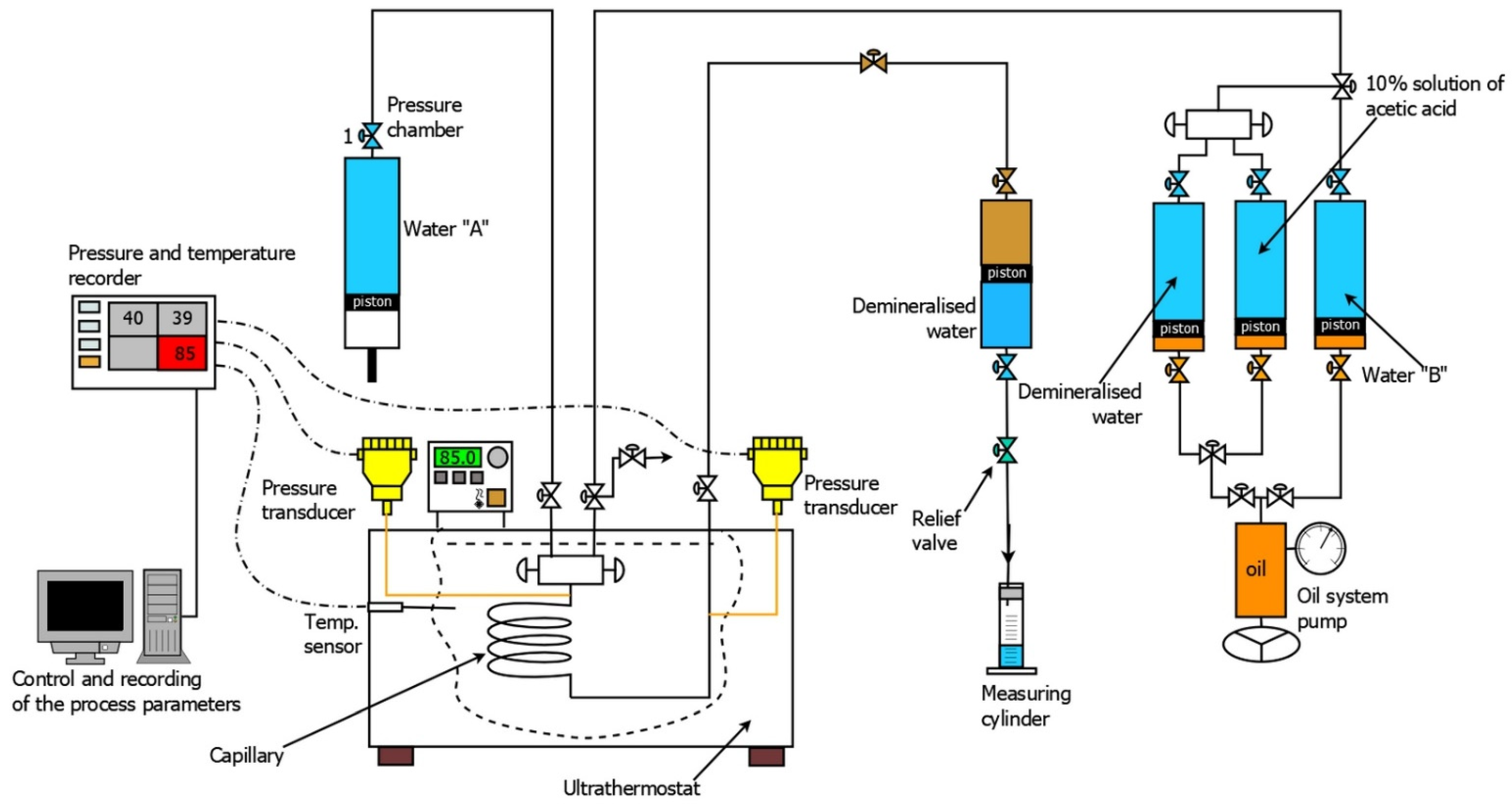
2.2. Description of the Apparatus Used for the Research and the Research Methodology
3. Results
3.1. Research with the Use of Geothermal Waters
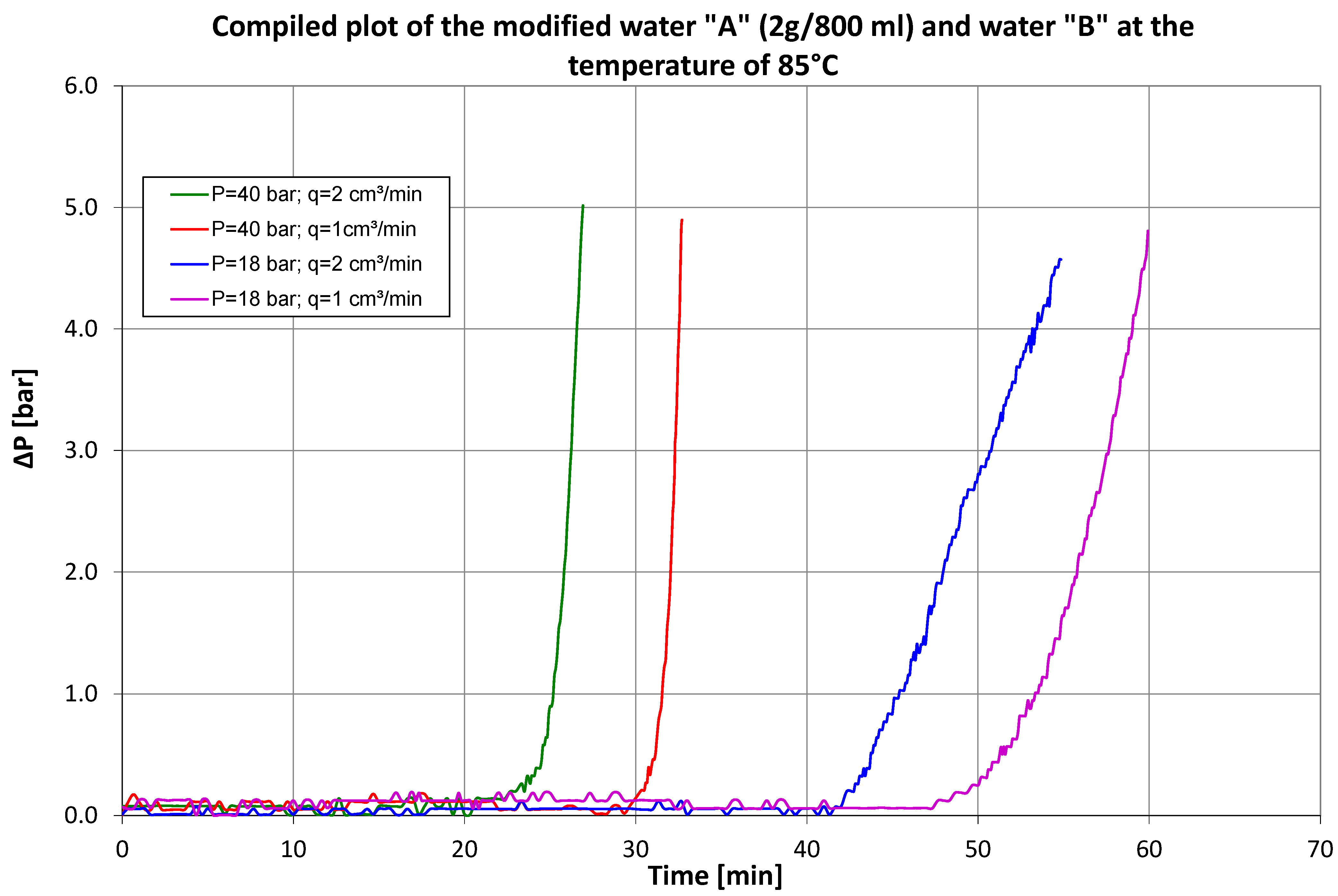
3.2. Tests on Geothermal Water (Modified with 2 g of Sodium Bicarbonate per 800 mL)
3.3. Tests on Geothermal Water (Modified with 1 g of Sodium Bicarbonate per 800 mL)
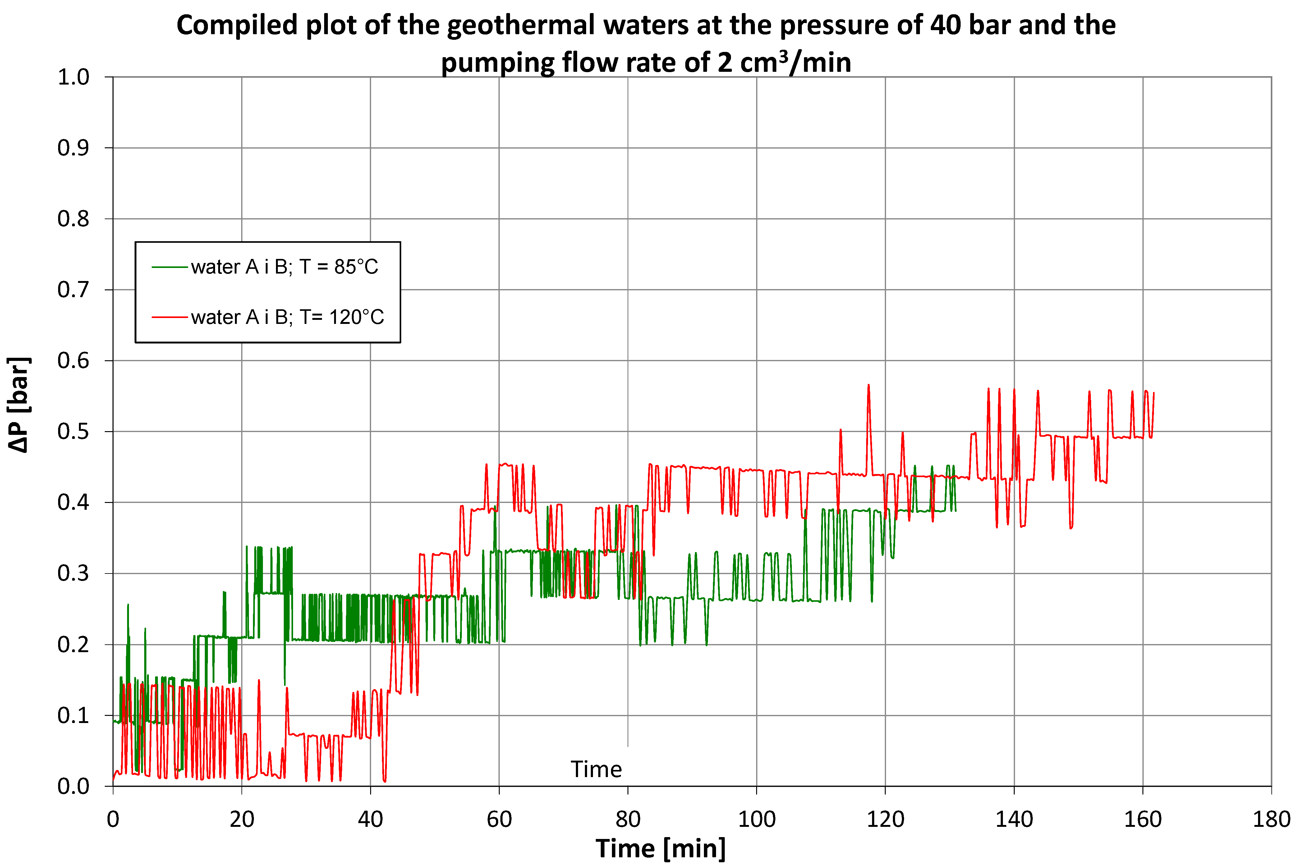
3.4. Long-Term Test for Geothermal Waters “A” and “B”
4. Discussion
5. Conclusions
- The test stand, which was made based on the PVT equipment in place, allows determination of the conditions of precipitation of inorganic sediments in geothermal waters in a dynamic test, following the recommendations set out in NACE TM0197-2010, No. 21228.
- Figure 5 shows the change in the capillary blocking time depending on the pressure and the liquid flow velocity at a temperature of 120 °C. For this temperature, the measurements were made at pressures of 18 and 40 bar and flows of 1 and 2 cm3/min for each of the brines. The blocking time of the capillary was between 9–20 min. The graph also shows the different nature of the curves depending on the pressure level. At 40 bar, the pressure will increase more rapidly, which means that deposits will “build up” in the conduit faster, while at 18 bar, the pressure increase is much smoother. This is due to the much slower accumulation of inorganic deposits on the capillary walls.
- The test series conducted using geothermal waters under the given dynamic test conditions (pressure, temperature, flow rate) confirmed the suitability of using PVT equipment to determine the conditions of precipitation of inorganic sediments in geothermal projects.
- To eliminate the risk of deposition of solids in geothermal waters, it is necessary to select and introduce appropriate inhibitor/inhibitors.
- The selection of inhibitors is affected by many factors, including the type and intensity of sediments, the chemical composition of the water and the method of introducing the inhibitor into the circuit.
- Solid sediments inhibitors, as well as other chemicals used, e.g., paraffin inhibitors, must be periodically adjusted to be adequate for the changing chemistry of the extracted and reinjected brine [30].
Author Contributions
Funding
Institutional Review Board Statement
Informed Consent Statement
Data Availability Statement
Conflicts of Interest
Nomenclature
| PVT | Pressure, Volume, Temperature—shorthand for name of device for the study of phase changes; |
| RES | renewable energy source; |
| NACE | International, a not-for-profit professional organization for the corrosion control industry whose mission is to “[equip] society to protect people, assets and the environment from the adverse effects of corrosion”. NACE International’s membership includes engineers, inspectors, technicians, scientists, business owners, executives, researchers, educators, students and others. The association is organized into four areas in North America and four global areas. NACE International has 142 sections, including 33 student sections worldwide, which sponsor local programs to promote the exchange of corrosion information and education. Among NACE members, the main focus of activities includes cathodic protection, coatings for industry, inspection, corrosion testing and material selection for specific chemical resistance; |
| pH | quantitative scale of acidity and alkalinity of aqueous solutions of chemical compounds; |
| mg/L | the number of milligrams dissolved in a liter of solution; |
| bar | pressure unit; |
| ΔP (bar) | differential pressure; |
| cm3/min | unit of flow rate; |
| g/800 mL | the amount dissolved in 800 mL of liquid; |
| P | Pressure; |
| T | Temperature; |
| q | Pumping speed; |
| TBT | Tube Blocking Test. |
References
- Ryżyński, G.; Majer, E. Geotermia niskotemperaturowa: Informacja geologiczna i procedury prawne. Prz. Geol. 2015, 63, 1388–1396. [Google Scholar]
- Kępińska, B. Przegląd stanu wykorzystania energii geotermalnej w Polsce w latach 2016–2018. Tech. Poszuk. Geol. 2018, 57, 11–27. [Google Scholar]
- Hajto, M. Potencjał geotermalny Polski oraz możliwości adaptacji międzynarodowej klasyfikacji zasobów geotermalnych UNFC-2009. Naft.-Gaz 2018, 74, 898–904. [Google Scholar] [CrossRef]
- Muffler, P.; Cataldi, R. Methods for regional assessment of geothermal resources. Geothermics 1978, 7, 53–89. [Google Scholar] [CrossRef] [Green Version]
- Górecki, W. (Ed.) Atlas Zasobów Geotermalnych Formacji Mezozoicznej na Niżu Polskim; Ministerstwo Środowiska: Kraków, Poland, 2006. [Google Scholar]
- Ustawa z Dnia 9 Czerwca 2011r. Prawo Geologiczne i Górnicze. Dz.U. Z 2021r.Poz.1420. Available online: https://isap.sejm.gov.pl/isap.nsf/download.xsp/WDU20210001420/T/D20211420L.pdf (accessed on 11 September 2021).
- Hajto, M. Geothermal water resource base in the Polish Lowlands—Geological and hydrogeological conditions of localization of prosp. Geol. Geophys. Environ. 2008, 34, 503–526. [Google Scholar]
- Kępińska, B. Energia geotermalna w Polsce—Stan wykorzystania, perspektywy rozwoju. Tech. Poszuk. Geol. 2011, 50, 7–18. [Google Scholar]
- European Geothermal Energy Council. EGEC Geothermal Market Report; European Geothermal Energy Council: Brussels, Belgium, 2020. [Google Scholar]
- Dziadzio, P.S.; Maj, J.; Jerzak, M.; Ofiara, K.; Bąk, D.; Kuoe, B. Geotermia w Polsce-rozwój stymulowany przez oerodki subfunduszu geologicznego Narodowego Funduszu Ochrony Środowiska i Gospodarki Wodnej. Prz. Geol. 2020, 68, 151–155. [Google Scholar]
- Berent-Kowalska, G.; Jurgaś, A.; Kacprowska, J.; Pawelczyk, M.; Szymańska, M.; Moskal, I. Energia ze Źródeł Odnawialnych w 2019 Roku; Główny Urząd Statystyczny: Warsaw, Poland, 2020; pp. 1–92. [Google Scholar]
- Browne, P.R. Hydrothermal Alteration and Reservoir Rock Type; Lectures on Geothermal Geology and Petrology. UNU Geothermal Training Programme. Report 2; National Energy Authority: Reykjavik, Iceland, 1984.
- Brown, K. Mineral Scaling in Geothermal Power Plant; United Nations University Geothermal Training Programme; United Nations University: Reykjavik, Iceland, 2013; pp. 1–30. [Google Scholar]
- Shannon, D.W. Economic Impact of Corrosion and Scaling Problems in Geothermal Energy Systems; Battelle Pacific Northwest Labs: Richland, WA, USA, 1975. [CrossRef] [Green Version]
- Andritsos, N.; Karabelas, A.J.; Koutsoukos, P.; Scale Formation in Geothermal Plants. International Summer School on Direct Application of Geothermal Energy. 2002, pp. 179–189. Available online: https://www.researchgate.net/publication/248390587_SCALE_FORMATION_IN_GEOTHERMAL_PLANTS (accessed on 19 November 2021).
- Owen, L.; Michels, D. Geochemical Engineering Reference Manual; Department of Energy: Oakland, CA, USA, 1984. [CrossRef] [Green Version]
- Watson, A. Geothermal Engineering: Fundamentals and Applications; Springer: New York, NY, USA, 2014. [Google Scholar]
- Corsi, R. Scaling and corrosion in geothermal equipment: Problems and preventive measures. Geothermics 1986, 15, 839–856. [Google Scholar] [CrossRef]
- Marty, B.; Criaud, A.; Fouillac, C. Low enthalpy geothermal fluids from the Paris sedimentary basin-1. Characteristics and origin of gases. Geothermics 1988, 17, 619–633. [Google Scholar] [CrossRef]
- Mouchot, J.; Genter, A.; Cuenot, N.; Scheiber, J.; Seibel, O.; Bosia, C.; Ravier, G.; Mouchot, J.; Genter, A.; Cuenot, N. First year of operation from EGS geothermal plants in Alsace, France: Scaling issues. In Proceedings of the 43rd Workshop on Geothermal Reservoir Engineering, Stanford, CA, USA, 12–14 February 2018. [Google Scholar]
- Kuśnierczyk, J. Badania Skuteczności Działania Inhibitorów Siarczanu Baru i Strontu w Warunkach Testu Dynamicznego. Zlecenie Wew; INiG-PIB 002/KB; INiG-PIB: Krosno, Poland, 2018. [Google Scholar]
- Szymczak, S.; Shen, D.; Higgins, R.; Gupta, D.V.S. Minimizing environmental and economic risks with a proppant-sized solid-scale-inhibitor additive in the bakken formation. SPE Prod. Oper. 2014, 29, 14–20. [Google Scholar] [CrossRef]
- Schilter, R.; Yang, C.; Hill, M.; Watson, P.; Mac Ewen, K.; Almond, S. Field-detectable scale inhibitor for severe oilfield environments. In Proceedings of the SPE Deepwater Drilling and Completions Conference, Galveston, TX, USA, 10–11 September 2014. SPE-170296. [Google Scholar]
- Todd, M.J.; Wylde, J.J.; Strachan, C.J.; Moir, G.; Thornton, A.; Goulding, J. Phosphorus functionalised polymeric scale inhibitors, further developments and field deployment. In Proceedings of the SPE International Conference on Oilfield Scale, Aberdeen, UK, 30–31 May 2012. SPE 154135. [Google Scholar]
- Hamouda, A.A. Insight into sulfate in high-salinity producers and selection of scale inhibitor. In Proceedings of the 64th Annual Technical Conference and Exhibition of the Society of Petroleum Engineers (SPE), San Antonio, TX, USA, 8–11 October 1989. Paper No. SPE 19764. [Google Scholar]
- Schalge, A.L.; Dormish, F.L. The evaluation of scale inhibitors for high BaSO4 scaling potential using a new tube/filter blocking apparatus. In Proceedings of the SPE International Symposium on Oilfield Chemistry of the Society of Petroleum Engineers, Houston, TX, USA, 8–10 February 1989. [Google Scholar]
- Khormali, A.; Petrakov, D.G.; Moghaddam, R.N. Study of adsorption/desorption properties of a new scale inhibitor package to prevent calcium carbonate formation during water injection in oil reservoirs. J. Pet. Sci. Eng. 2017, 153, 257–267. [Google Scholar] [CrossRef]
- Szuflita, S.; Kuśnierczyk, J.; Wojnicki, M.; Warnecki, M. Badania laboratoryjne określające wzrost potencjału parafinowania wraz ze spadkiem temperatury. Nafta-Gaz 2018, 74, 759–767. [Google Scholar] [CrossRef]
- Kuśnierczyk, J. Badania Skuteczności Działania Inhibitorów Osadów Nieorganicznych w Warunkach Testu Dynamicznego. Zlecenie Wew; INiG-PIB 0045/KB; INiG-PIB: Krosno, Poland, 2017. [Google Scholar]
- Vakhin, A.V.; Morozov, V.P.; Sitnov, S.A.; Eskin, A.A.; Petrovnina, M.S.; Nurgaliev, D.K.; Kayukova, G.P.; Romanov, G.V.; Yusupova, T.N. Application of thermal investigation methods in developing heavy-oil production technologies. Chem. Technol. Fuels Oils 2015, 50, 569–578. [Google Scholar] [CrossRef]


| Parameters | Unit | Water A | Water B |
|---|---|---|---|
| Reaction | pH | 7.5 | 7.1 |
| Chlorides | mg/L | 483 | 478 |
| Bromides | mg/L | 0.88 | 0.88 |
| Sulfates | mg/L | 1060 | 950 |
| Sodium | mg/L | 520 | 490 |
| Potassium | mg/L | 51 | 49 |
| Magnesium | mg/L | 47 | 45 |
| Calcium | mg/L | 230 | 230 |
| General mineralization | mg/L | 2650 | 2550 |
| Item | Test Temperature [°C] | Test Pressure [bar] | Pumping Flow Rate [cm3/min] | Build-Up Start [min] | End of the Test [min] | Differential Pressure (Final) [bar] | Sodium Bicarbonate Concentration [800 g/mL] |
|---|---|---|---|---|---|---|---|
| 1 | 85 | 40 | 2 | Brine flow is not blocked | - | ||
| 2 | 120 | 40 | 2 | Brine flow is not blocked | - | ||
| 3 | 85 | 40 | 1 | 30.0 | 32.7 | 4.897 | 2 |
| 4 | 85 | 40 | 2 | 20.7 | 26.9 | 5.014 | 2 |
| 5 | 85 | 18 | 1 | 47.7 | 59.9 | 4.806 | 2 |
| 6 | 85 | 18 | 2 | 42.0 | 54.9 | 4.570 | 2 |
| 7 | 120 | 40 | 1 | 10.8 | 13.7 | 4.749 | 2 |
| 8 | 120 | 40 | 2 | 8.3 | 11.3 | 4.777 | 2 |
| 9 | 120 | 18 | 1 | 20.2 | 40.1 | 4.712 | 2 |
| 10 | 120 | 18 | 2 | 15.0 | 26.1 | 4.867 | 2 |
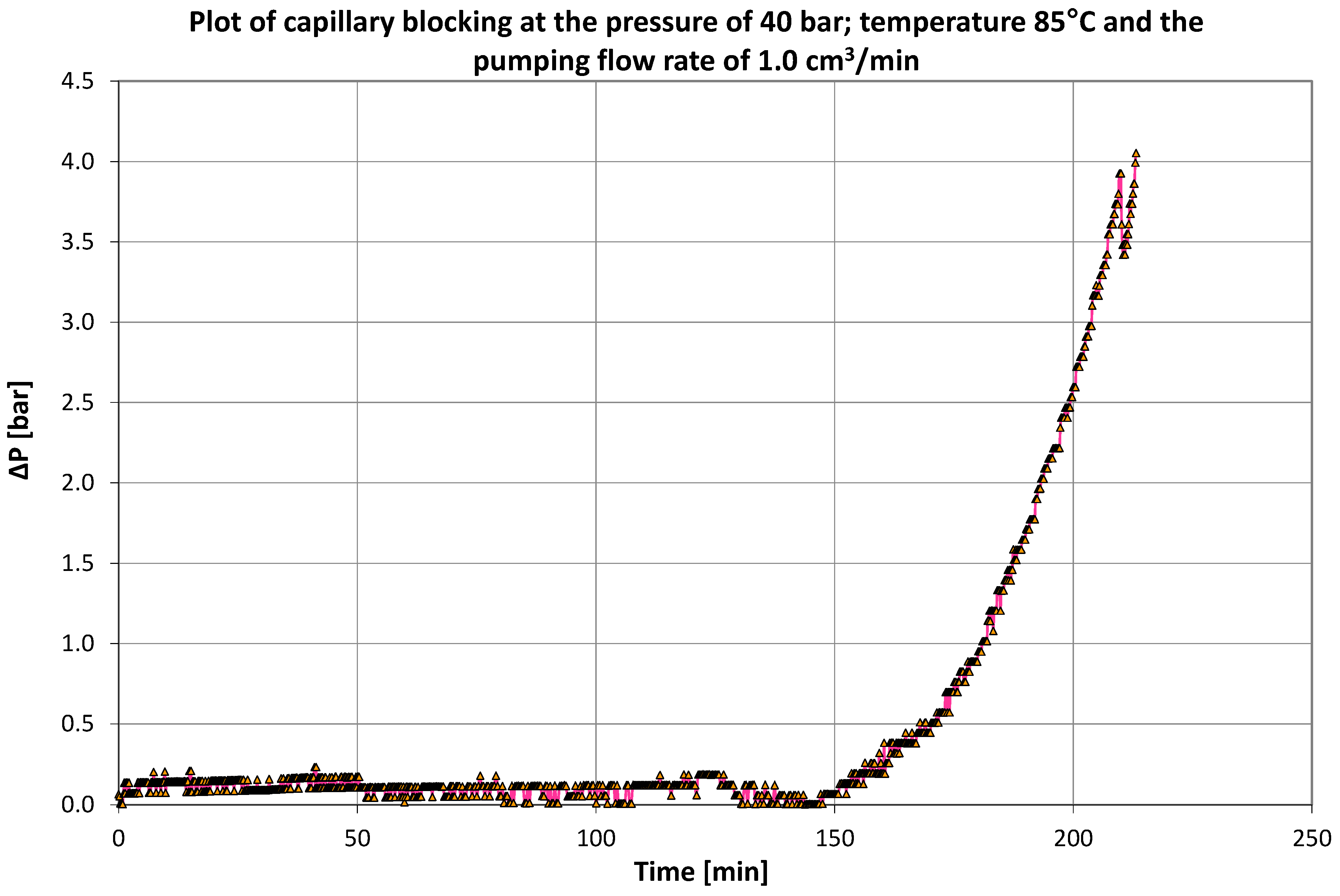
| 11 | 85 | 40 | 1 | 151.1 | 213.1 | 4.053 | 1 |
| 12 | 120 | 40 | 1 | 31.4 | 42.2 | 4.663 | 1 |
| 13 | 120 | 40 | 2 | 26.0 | 40.9 | 4.305 | 1 |
| 14 | 120 | 18 | 1 | 42.0 | 65.3 | 4.815 | 1 |
| 15 | 120 | 18 | 2 | 36.5 | 67.9 | 3.304 | 1 |
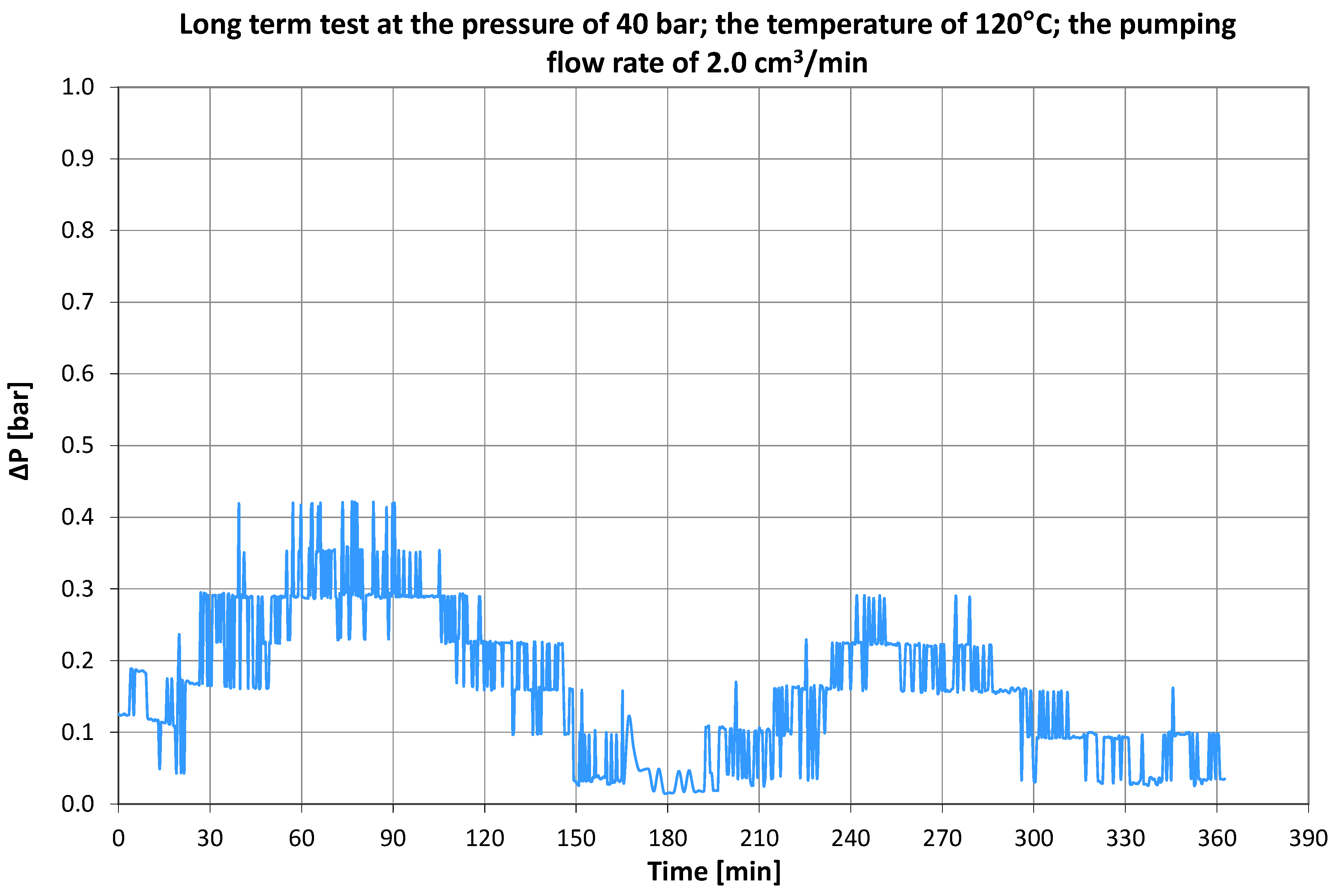
| 16 | 120 | 40 | 2 | Brine flow is not blocked—long-term test (end of the test: after 362.5 min) | |||
Publisher’s Note: MDPI stays neutral with regard to jurisdictional claims in published maps and institutional affiliations. |
© 2022 by the authors. Licensee MDPI, Basel, Switzerland. This article is an open access article distributed under the terms and conditions of the Creative Commons Attribution (CC BY) license (https://creativecommons.org/licenses/by/4.0/).
Share and Cite
Kuśnierczyk, J.; Szuflita, S.; Wojnicki, M.; Warnecki, M.; Kremieniewski, M. The Use of Equipment for the Study of Phase Changes to Determine the Conditions of Precipitation of Inorganic Sediments in Geothermal Waters. Energies 2022, 15, 2229. https://doi.org/10.3390/en15062229
Kuśnierczyk J, Szuflita S, Wojnicki M, Warnecki M, Kremieniewski M. The Use of Equipment for the Study of Phase Changes to Determine the Conditions of Precipitation of Inorganic Sediments in Geothermal Waters. Energies. 2022; 15(6):2229. https://doi.org/10.3390/en15062229
Chicago/Turabian StyleKuśnierczyk, Jerzy, Sławomir Szuflita, Mirosław Wojnicki, Marcin Warnecki, and Marcin Kremieniewski. 2022. "The Use of Equipment for the Study of Phase Changes to Determine the Conditions of Precipitation of Inorganic Sediments in Geothermal Waters" Energies 15, no. 6: 2229. https://doi.org/10.3390/en15062229
APA StyleKuśnierczyk, J., Szuflita, S., Wojnicki, M., Warnecki, M., & Kremieniewski, M. (2022). The Use of Equipment for the Study of Phase Changes to Determine the Conditions of Precipitation of Inorganic Sediments in Geothermal Waters. Energies, 15(6), 2229. https://doi.org/10.3390/en15062229