Article

Numerical Simulation on the Structural Design of a Multi-Pore Water Diffuser during the External Ice Melting Process of an Ice Storage System

1
State Grid Zhejiang Electric Power Co., Ltd., Hangzhou 310000, China
2
State Grid Jinhua Power Supply Company, Jinhua 321000, China
3
Nari Group Corporation, State Grid Electric Power Research Institute, Nanjing 211000, China
4
Tianjin Key Laboratory of Refrigeration Technology, Tianjin University of Commerce, Tianjin 300134, China
*
Authors to whom correspondence should be addressed.
Energies 2022, 15(6), 2181; https://doi.org/10.3390/en15062181
Submission received: 27 January 2022 / Revised: 27 February 2022 / Accepted: 9 March 2022 / Published: 16 March 2022
(This article belongs to the Special Issue Advances in Heat and Mass Transfer and Reaction in Porous Media)

Abstract

:
A water diffuser is a critical auxiliary equipment for an ice storage system during the external ice melting process. This paper proposes a linear multi-pore water diffuser for an ice storage system with 500 t of refrigeration capacity to enhance the performance of external ice melting. By establishing a three-dimensional two-phase volume of fluid (VOF) model, different structural designs of water diffusers for the ice storage device are numerically examined regarding the degree of turbulence, flow velocity, and pressure drop. The results show that the optimal water diffuser with five rows of trunk pipe and six perforated pores arranged in per row of branch pipe with a 4 mm diameter of perforated pores exhibiting a relatively lower degree of turbulence with a lower pressure drop compared with the other designs in this study. Meanwhile, the influence of the flow velocity on the ice melting process is also investigated by a numerical model of ice melting. It is found that the fed flow velocity from the main pipe inlet exhibits a great impact on the external ice melting process. Compared with the external ice melting process without the water diffuser, the external ice melting process with optimal water diffuser design under flow velocity of 1.0 m s−1 could shorten the overall ice-melting time by 16 h. Additionally, through adjusting the water flow velocity, different output cooling can be realized to provide a fast response speed to the cooling variations in demand of the terminal users with a reduced cost.

1. Introduction

Rapid economic development has resulted in insufficient peak power supply. Energy storage technology has proved to be an effective way to solve this problem, which can bring good social and economic benefits that are expressed in various aspects [1,2,3,4,5]. Ice storage technology uses the latent heat of ice to store the cold energy produced by the power grid during the low electricity consumption period, and releases the cold energy during the daytime peak electricity consumption period to provide for the air conditioning system to relieve the pressure on the power grid during the daytime peak period. Therefore, energy storage technology plays an important role in shifting peaks and filling valleys of electric load [6,7,8,9,10]. For example, in solar systems, the energy can be absorbed during daylight and this stored energy can be used at night for heating purposes [11,12].
Generally, ice storage technology can be divided into the internal and external ice melting system. Compared with the internal ice melting system, the external ice melting system can effectively reduce the heat transfer resistance of the ice melting process owing to the return-water contacting directly with the ice and water [13]. It is reported that the performance of an ice melting system is closely related to the design of the auxiliary equipment of the water diffuser [14]. Therefore, great efforts have been made regarding the design of water diffusers for external ice melting systems [15].
Water diffusers are commonly used in external ice melting systems, condensers in power plants [16], seawater treatment equipment [17,18], and sewage treatment reactors. The main types of water diffusers are linear, disc, trough, octagonal, and radial shapes [19]. The octagonal, radial, and disc water diffusers are well-suited to round, cylindrical tanks, whereas the H-type water diffusers are more appropriate for square and rectangular tanks, although they suffer from maintaining self-balance. For example, Tang et al. [16] reported that the large-scale chilled water storage device with a well-designed octagonal diffuser and uniform flow orifice could achieve ideal storage efficiency under the operation conditions of large flow rate and large temperature difference. Ling et al. [20] analyzed the influence of Reynolds number (Re), Froude number (Fr), and H-type water diffuser on the efficiency and performance of a water pool. By using three-dimensional unsteady numerical experiments, Chung et al. [21] investigated the structure of a radial and an H-beam type diffuser on the performance of a storage tank and found that water diffuser shape played a significant role on the performance of a stratified thermal storage tank. Karim [22] reported the experimental results of an octagonal diffuser in an energy storage system and suggested that the diffuser should be designed on unit Froude number (1/Ri1/2) and equal pressure drop. In another investigation by Song et al. [23], it was conveyed that there was significant improvement in the stratification in an octagonal slotted pipe diffuser for energy storage. Cui et al. [24,25] determined the structure and operating parameters of the throttle valve water distributor and related evaluation, which has a good guiding role for the design of the pre-throttle valve water distributor. To get the higher energy storage efficiency, Tang et al. [26] employed a numerical investigation on the optimization of the octagonal water diffuser with a uniform flow orifice plate. The optimal design of the water distributor improves its efficiency in the heat exchanger [27]. Jia et al. [28] proposed a control strategy for the flow of the water distributor, and the experimental results show that the strategy can improve the response speed of the system. Therefore, the optimal design of water diffuser is of great importance for the enhanced performance of an energy storage system. However, recently, many numerical studies only focus on the design of the structure and operating condition of a water diffuser, seldomly has published work numerically examined the effect of water diffuser design on the performance of the external ice melting system.
Therefore, this study establishes a hybrid model combining the water diffuser model and the ice-melting model for a rectangular shaped ice storage system with 500 t of refrigeration. By the water diffuser model, the influence of the structural parameters of the auxiliary equipment, a linear multi-pore water diffuser, such as the diameter of the perforated pore, the number of the pipe rows and the perforated pore per row, on the performance of the multi-pore water diffuser is numerically investigated. Subsequently, the effect of the fed water velocity of the main inlet on the performance of the external ice melting process regarding the ice-melting time, outlet water temperature, and output cooling capacity is evaluated based on the above results. The objective of this study is to seek an optimal combination of structure design and operating conditions of the water diffuser by the developed hybrid model, therefore to achieve a high performance of the external ice melting system with fast response and cost savings, ultimately satisfying the changing cooling requirements of the users.

2. Mathematics Model

2.1. Computational Domain

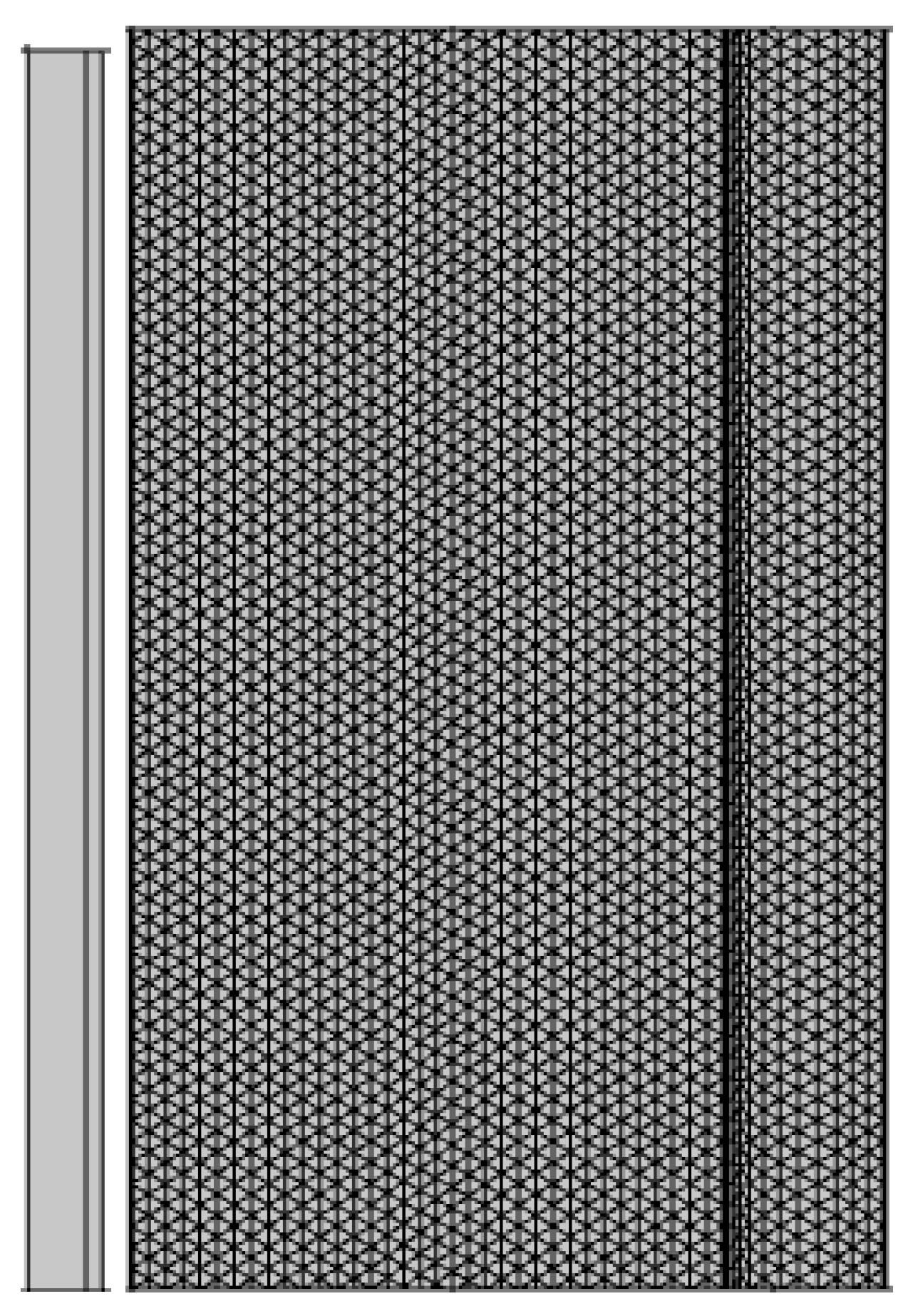
Linear multi-pore water diffuser is employed to enhance the performance of an external ice melting system. The length, width, and height of the external ice melting device including the linear multi-pore water diffuser are 4.8, 3.15, and 1.85 m, respectively, as shown in Figure 1a. The multi-pore water diffuser is designed above the coil of the external ice melting device, which consists of a main pipe and a branch pipe as shown in Figure 1a. The ice storage capacity of the external ice melting system is 500 t of refrigeration and the ice melting time should be controlled within 4 h, therefore, based on the equation Q = cm∆T (where c is the specific heat capacity, m is the mass of the object, and ∆T is the temperature change of the object), the diameter of the main pipe, trunk pipe, and branch pipe of the linear multi-pore water diffuser are calculated to be 32, 25, and 15 mm, respectively. To save computational time, a simplified geometric model without considering the coil is employed in this simulation as also indicated in Figure 1a. Figure 1b shows the overall generated unstructured grid of the computational domain, the average quality of the grid is 0.86. Moreover, the grid dependence is carried out successfully with increasing or decreasing the total grid number of 30%, it is found that the difference between the numerical results with a different grid number is less than 1.0%.

2.2. Model Assumptions and Governing Equations

The two-phase flow water diffuser model is developed with the following assumptions: the water diffuser operates under steady-state conditions; the physical properties of the fluid in the water diffuser are constant; the flow is stable and in a turbulent state; and the fluid is viscous and incompressible. The effect of gravity is considered. Owing to the turbulent flow within the water diffuser, a K-ε model of turbulence is employed in this study. Base on the published work regarding water diffusers [29], the complete mathematical model equations of the model are provided as follows.
The continuity equation and momentum equations for liquid water are:
( γ w ρ u i ) x i = 0
( γ w ρ u i u j ) x = γ w P x j   + γ w ( μ u i ) x i + γ w ρ g ( i , j = 1 , 2 , 3 )
where γw is the volume fraction of the liquid phase, ρ (kg m−3) is the density of liquid water; μ (Pa∙s) is the viscosity of liquid water; P(Pa) is the pressure; u (m s−1) is the liquid water velocity; and g (Kg s−1) is the gravity vector. The continuity and momentum conservation equations for the gas phase are in the same form as Equations (1) and (2).
The k-ε turbulence model is derived from the instantaneous Navier–Stokes. The equations of the turbulent kinetic energy k and the turbulent kinetic energy dissipation rate ε in the model are as follows:
The equations of the turbulent kinetic energy k:
( ρ k μ i ) = x i [ ( μ + μ i σ k ) k x j ] + G k + G b ρ ε + S k
The turbulent kinetic energy dissipation rate ε:
x i ( ρ ε μ i ) = x j [ ( μ + μ i σ ε ) ε x j ] + C 1 ε ε k ( G k + C 3 ε G b ) C 2 ε ρ ε 2 k + S ε
where the turbulent viscosity, ut = ρ C u k 2 ε ; C u = 0.09; Gk = − ρ u i u j ¯ μ i x i is the turbulent kinetic energy due to velocity steps in the bottom laminar flow, G b = g i   μ t ρ P r t ρ x i is turbulent kinetic energy due to buoyancy; P r t = 0.85   is   the turbulent energy Prandtl number; C1 = 1.44, C2 = 1.9, and C 3 = 1 are constant in the model; σk = 1.0 and σε = 1.2 are the Pranftl number in turbulent kinetic energy k equation and in diffusion equation ε; and Sk and Sε are the source terms of the equations.

2.3. Boundary Conditions

The boundary conditions of two-phase water diffuser model are shown in Table 1. All of the external walls are treated as a non-slip boundary and the acceleration of gravity is set at 9.8 m/s. The velocity boundary is prescribed on main pipe inlet with a constant velocity of 1.0 m/s and the return water outlet is set as pressure outlet boundary.

2.4. Grid Independence Test and Model Validity

Grid independence verification is crucial to the simulation results. The grid independence was successfully performed by increasing and decreasing the mesh number by 30% with the same calculation conditions. The numerical results, such as the average velocity of pores as indicated in the flowing figure, are consistent with each other’s between the different meshes. Appropriate under relaxation factors were applied for each variable to ensure a stable convergence and the iteration residual for all solving variables was fixed at 10–5. Moreover, the residual curves are maintained for about 1000 steps without obvious differences, and the difference between the inlet and outlet mass flow is within 1.0%. Thus, it can be concluded that the model is reliable.

3. Results and Discussion

The influence of the water diffuser structural parameters on the degree of turbulence, flow velocity, and pressure drop of water distribution is numerical investigated in Section 3.1, Section 3.2 and Section 3.3. There are a total of 12 cases regarding the structural parameter designs of the water diffuser as shown in Table 2. Subsequently, the influence of operating parameters on ice melting process is examined in the Section 3.4 under the achieved optimal structural parameter designs of the water diffuser.

3.1. Influence of the Number of Trunk Pipes

This section investigates the influence of the number of trunk pipes on the degree of turbulence, flow velocity, and pressure drop of the water distribution. The number of trunk pipe rows are set at 3, 4, 5, 6, and 7 with the perforated pore diameter and the number of the perforated pores per row of branch pipe fixed at 4 mm and 6, respectively. Figure 2a shows the distribution of the velocity at the middle x–y plane of the branch pipe with three typical number of trunk pipe row designs, namely 3, 5, and 7. With the increase in the number of trunk pipe rows, the water velocity from the perforated pore decreases correspondingly, as also can be observed in Figure 2b. However, the degree of turbulence for water diffuser significantly decreases with the increase of the number of trunk pipe rows, indicating that increased number of pipe rows can improve the uniformity of water distribution for water diffuser. Nevertheless, these results do not reflect that a larger number of trunk pipe rows leads to a higher performance of water diffuser. As mentioned above, the linear multi-pore water diffuser suffers from maintaining self-balance, therefore, the maximum flow rate deviations for the branch pipes and perforated pore are also an important criterion to evaluate the performance of water diffuser. Moreover, the water diffuser should have a small pressure drop to save pump power consumption, which will be discussed below.
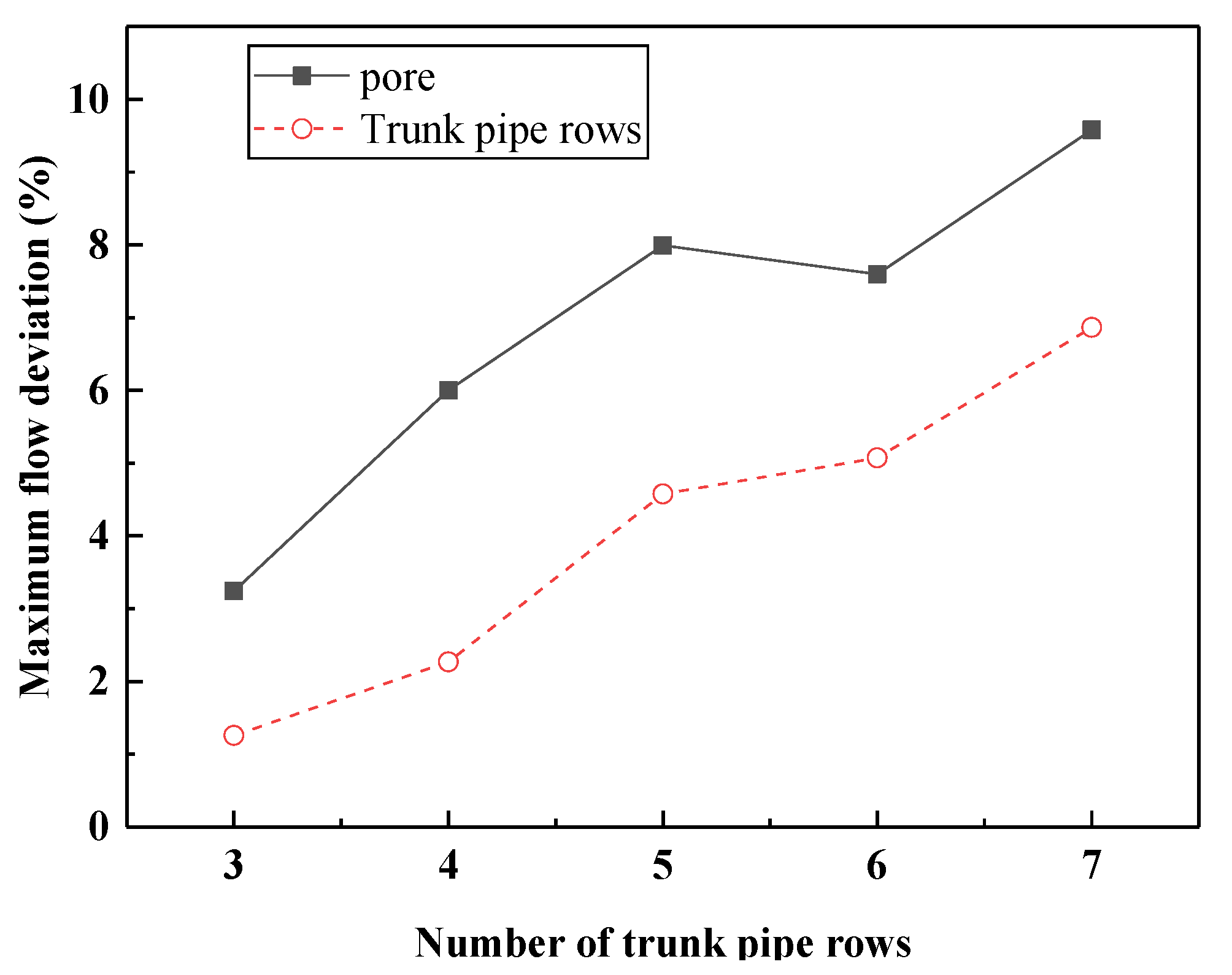
Figure 3 shows the maximum flow deviation for the branch pipes and the perforated pores under different numbers of trunk pipe rows. With the increase of the number of trunk pipe rows, the maximum flow deviations for the branch pipes and the perforated pores both increase. For instance, the maximum flow deviations for the branch pipes under the trunk pipe row of 3, 5, and 7 are 1.2%, 3.5%, and 5.7%, respectively, whereas for the perforated pores they are 3.6%, 8.1%, and 10.1%, respectively. These are caused by the decrease of the pressure within the trunk pipe resulting from the decreased flow rate. Generally, the maximum flow deviations for the water diffuser should be less than 10% [30]. Therefore, the water diffuser with the above number of trunk pipe rows satisfies the requirements of the maximum flow deviation. Figure 4 shows the maximum pressure drop and average velocity of the perforated pore for the water diffuser under different number of trunk pipe rows. With the increase of the number of trunk pipe rows, the pressure and the average velocity of the perforated pore for the water diffuser decrease. A decreased pressure favors saving pumping power; however, a reduced average velocity of the perforated pore can result in a decreased heat transfer coefficient, which is not conducive to ice melting for the external ice melting system.
Based on the above discussion, the water diffuser with five trunk pipe rows has a relatively smaller degree of turbulence, lower maximum flow deviation, and higher flow rate with a lower pressure drop; therefore, the number of trunk pipe rows for the water diffuser of the external ice melting system should be five in this study.

3.2. Influence of the Number of Perforated Pores

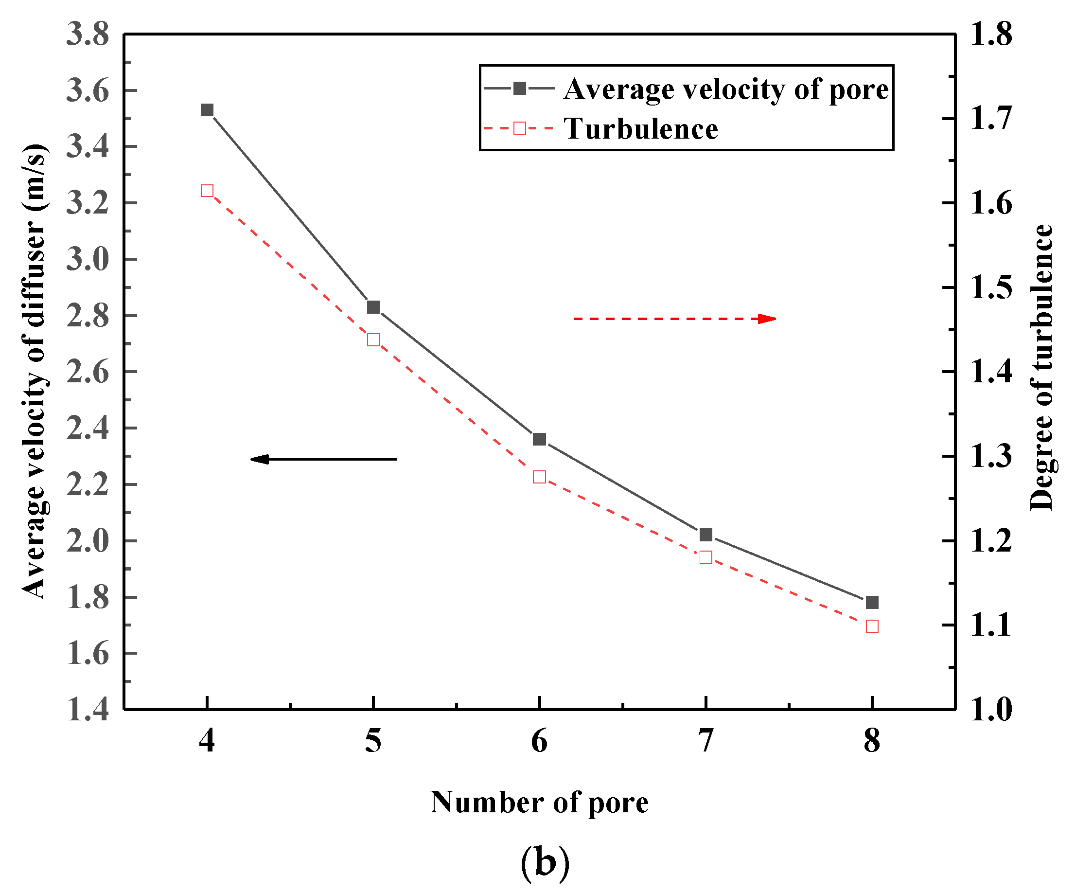
The influence of the number of perforated pores per branch row on the performance of the water diffuser is investigated in this section. The number of perforated pores per branch row is four, five, six, seven, and eight with a fixed number of trunk pipe of five and a maintained pore diameter of 6 mm, which are represented by DN6, DN7, DN3, DN8, and DN9. Figure 5 shows the distribution of the velocity at the middle x–y plane of the branch pipe and the average velocity and degree of the turbulence for the water diffuser under different number of perforated pores. An increased number of perforated pores per branch pipe leads to a decreased flow velocity within the pipes of the water diffuser as well as a reduced degree of turbulence for the water distribution. There also must be a tradeoff between the decreased flow velocity and the reduced degree of turbulence resulting from the increased number of perforated pores for a high performance of the water diffuser. This will be examined regarding the maximum flow deviation and pipeline pressure loss within the water diffuser as follows.
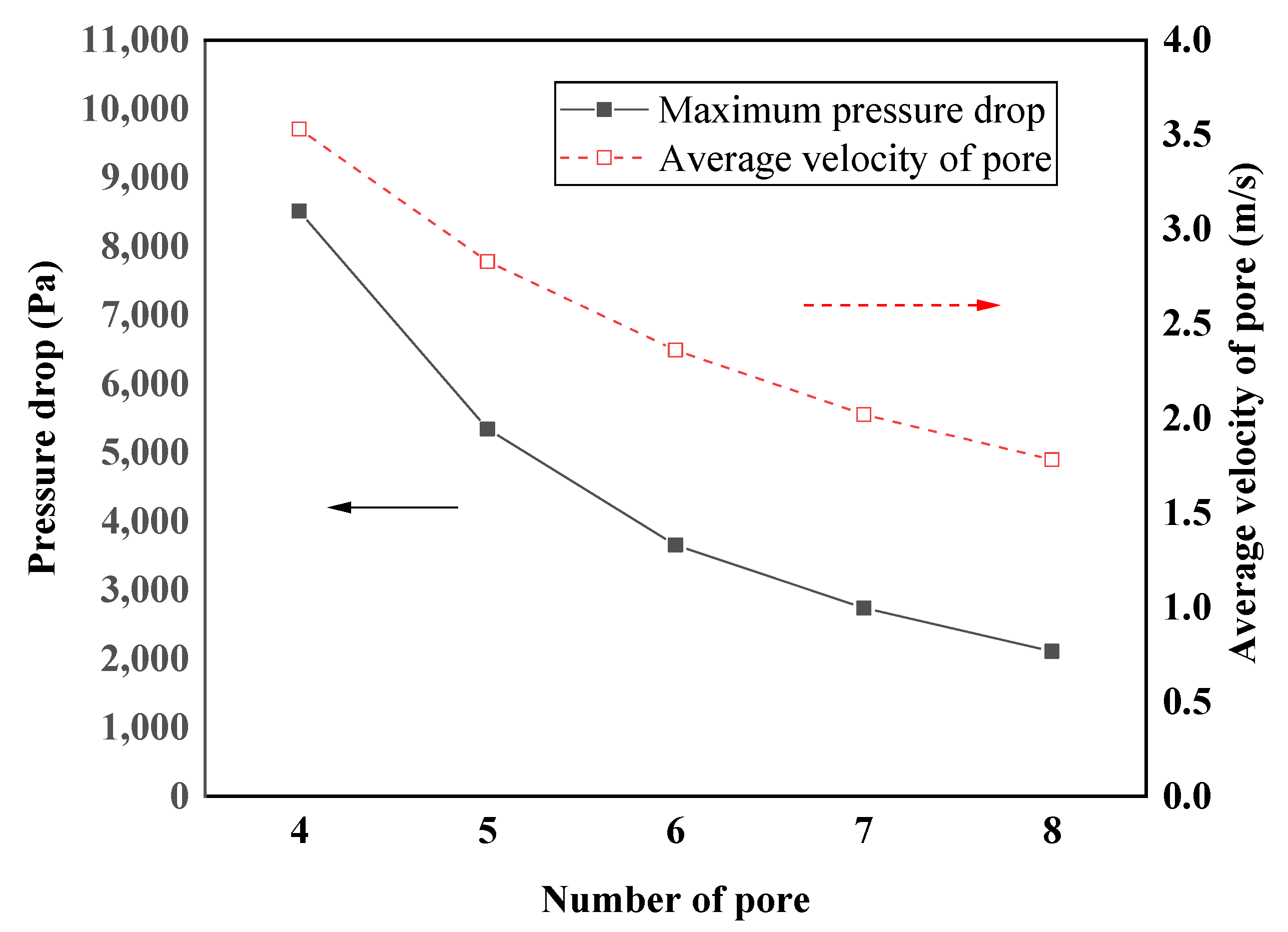
Figure 6 shows the maximum flow deviation for branch pipes and perforated pores of the water diffuser under a different number of perforated pores. It is found that the maximum flow deviation for branch pipes and perforated pores for all of the designed number of perforated pores are below 10%, indicating all of the designs that satisfy the requirement of the maximum flow deviation. The maximum pipeline pressure drops within the water diffuser and average velocity of perforated pore decrease with an increased number of perforated pores per branch row as shown in Figure 7. The result shows that with the number of perforated pores of six, the water diffuser has a lowest pipeline pressure drop and a relatively high velocity of water distribution.

3.3. Influence of the Diameter of the Diffuser

The influence of the perforated pore diameter of the water diffuser on the uniformity of water distribution, degree of turbulence, pipeline pressure loss for the water diffuser is examined in this section. The perforated pore diameters are chosen to be 4, 6, 8, and 10 mm, which correspond to DN3, DN10, DN11, and DN12, respectively. The number of trunk pipe rows and the number of the perforated pores per branch row is kept at five and six, respectively. Figure 8 shows the distribution of the velocity at the middle x–y plane of the branch pipe and the average velocity and degree of the turbulence for the water diffuser under different perforated pore diameters. An increased perforated pore diameter leads to a decreased velocity within the branch pipes and perforated pores, whereas the degree of the turbulence initially increases and then remarkably decreases. A lower velocity for the perforated pore is detrimental to the improvement of the heat transfer; however, it benefits the uniformity of the water distribution.
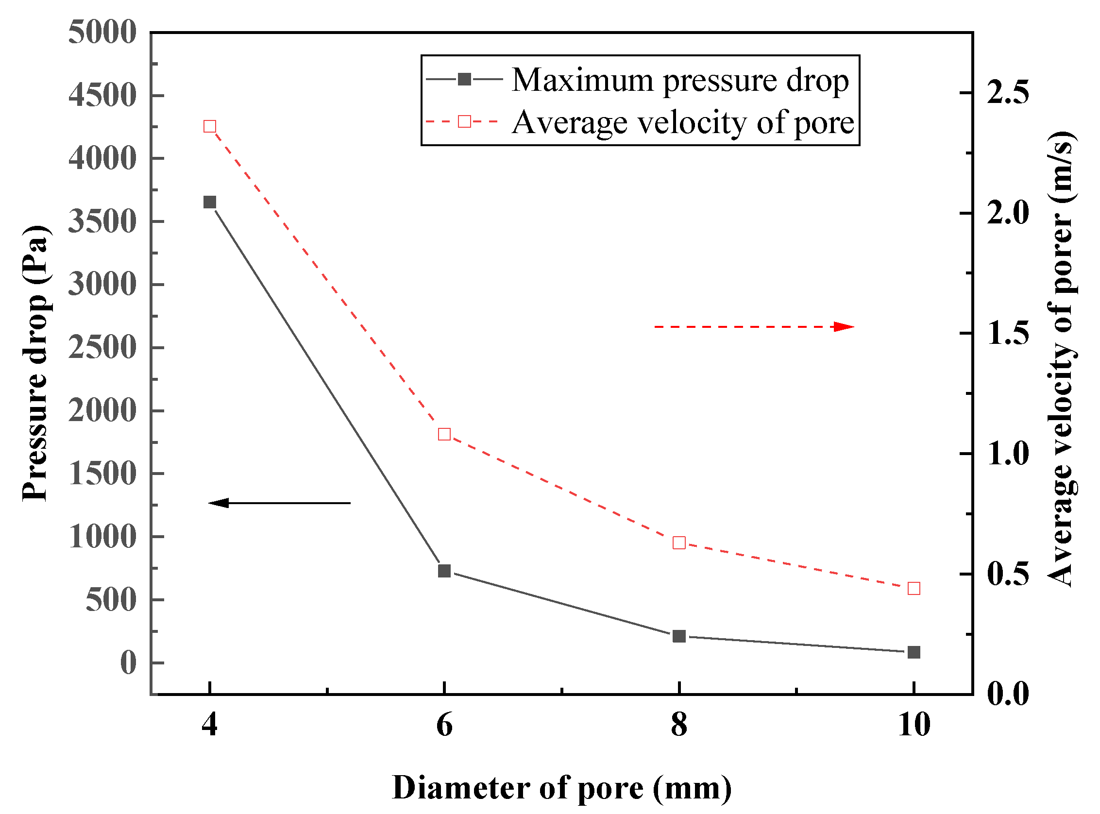
The maximum flow deviation for the branch pipes and the perforated pores of the water diffuser under different perforated pore diameters are shown in Figure 9. The maximum flow deviations for the branch pipes and perforated pores increase with the increase of the perforated pore diameter owing to the reduced pipeline pressure loss. The maximum flow deviation for the branch pipes is 8.5%, 18.2%, 85.6%, and 168%, whereas for the perforated pores they are 4.6%, 16.9%, 69.4%, and 131.1% under perforated pore diameter of 4, 6, 8, and 10 mm, respectively. As discussed above, the maximum flow deviation within the water diffuser should be less than 10%, thus the perforated pore diameter for the water diffuser should be 4 mm. As the influence of the number of trunk pipes on the pipeline pressure, with the increase of the perforated pore diameters, the pipeline pressure and the average velocity of the perforated pore for the water diffuser decrease. A lower pipeline pressure benefits energy saving; while a lower average velocity of the perforated pore decreases the heat transfer and degrades the efficiency of ice melting. As observed in Figure 10, the water diffuser with a perforated pore diameter of 4 mm has a relatively low pipeline pressure loss and a relatively high velocity of perforated pore, moreover, a low degree of turbulence as indicated in Figure 8; therefore, the perforated pore diameter of 4 mm should be employed for the water diffuser in this study.

3.4. Influence of an Operational Parameter on External Ice Melting Process

This section investigates the influence of an operational parameter, namely the flow velocity of the main pipe on the external ice melting process under the optimal structure of the water diffuser by using a numerical model of ice melting. As mentioned above, the external ice melting device including the linear multi-pore water diffuser is 4.8 × 3.15 × and 1.85 m, which has an ice storage capacity of 500 t of refrigeration. The ice thickness is 74 mm outside the U-shaped coil and the water gap between the ice layer of two outside the U-shaped coil is 18 mm under the ice storage fraction of 50%. To save the computational time, a 2-dimension half-cell of the U-shaped coil is applied as the computational domain owing to the symmetry as show in Figure 11.
The governing equations for the water diffuser model as provided above with temporal term incorporating the energy equation ( ρ C p T t + ρ C p u · T + · ( k T ) = Q ) is employed to develop the numerical model of ice melting. A commercial CFD soft COMSOL is employed to solve the developed multiphysics two-phase isothermal model with phase change. The impact of the operating parameters of the water diffuser, namely, the fed water velocity from the main pipe inlet on the external ice melting process is examined. In this simulation, the fed water velocity from the main pipe inlet is set to 0.5, 0.75, 1.0, 1.25, and 1.5 m s−1; the inlet water temperature is fixed at 10 °C; the initial water and ice temperature is set to 3 and 0 °C. The thermophysical properties of water and ice in this model are listed in Table 3. The velocity of the water distribution of the water diffuser is closely related to the fed water velocity from the main pipe inlet, the ice storage fraction and the structure and arrangement of the U-shaped coil, which is calculated in Table 4.
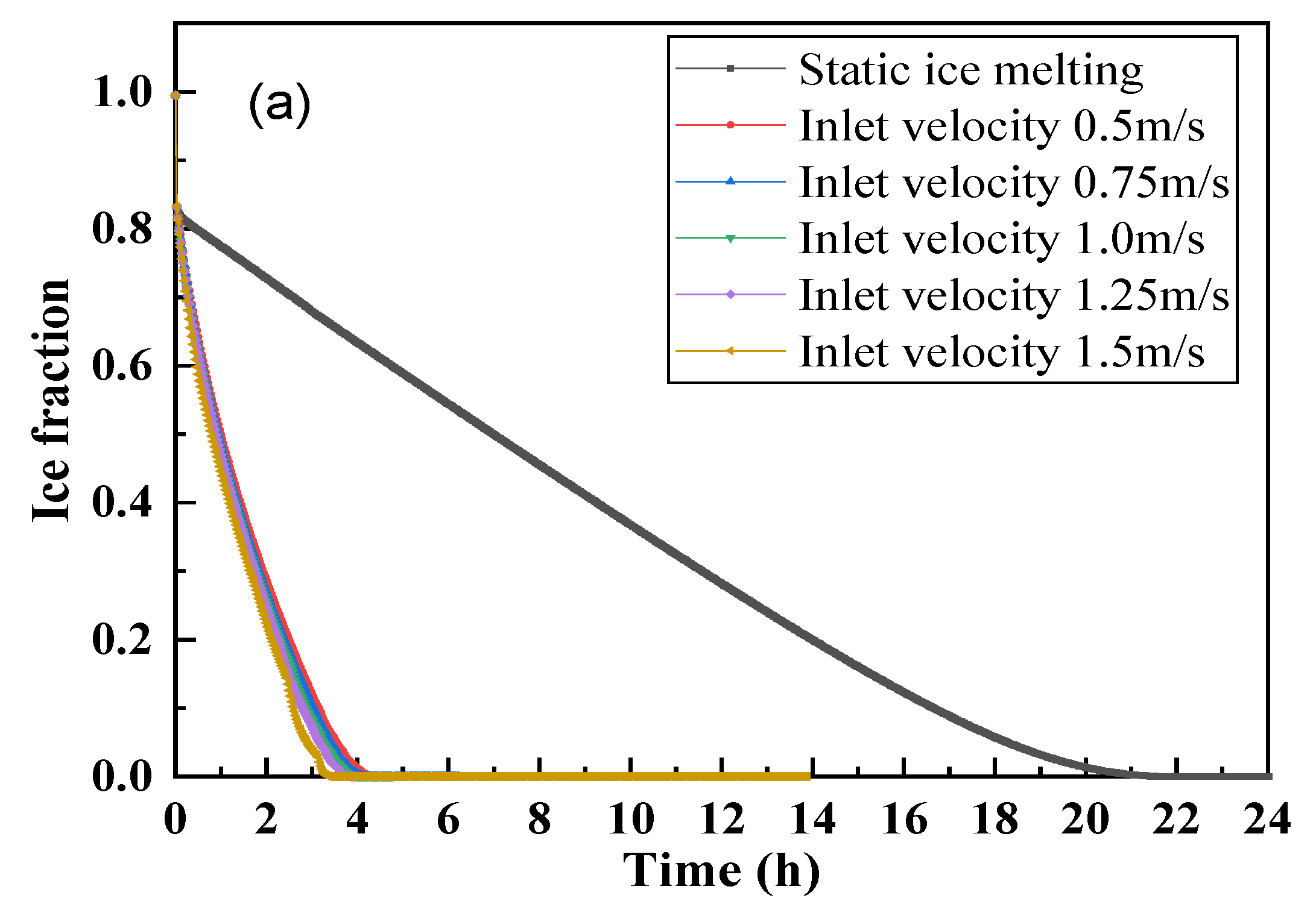
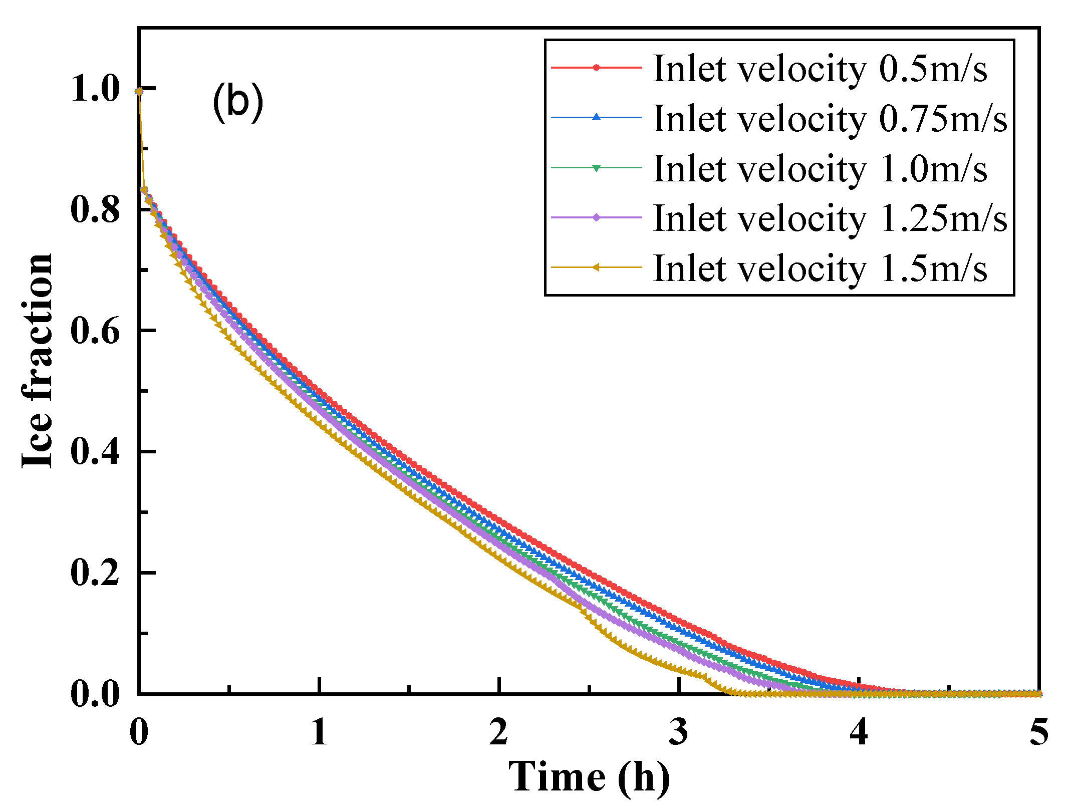
Figure 12 shows the curves for the variations of ice storage fraction for the external ice melting device with the time in the ice melting process under different fed water velocity from the main pipe inlet. The ice storage fraction decreases remarkably for the external ice melting device with the water diffuser compared to that without water diffuser (static ice melting). With the increase of the fed water velocity from the main pipe inlet, the time needed for complete ice melting decreases, for instance, the time needed for complete ice melting is 4.3, 4.1, 3.9, 3.7, and 3.4 h for fed water velocity from the main pipe inlet of 0.5, 0.75, 1.0, 1.25, and 1.5 m s−1, respectively. This is because the increase in flow velocity enhances the convective heat transfer effect.
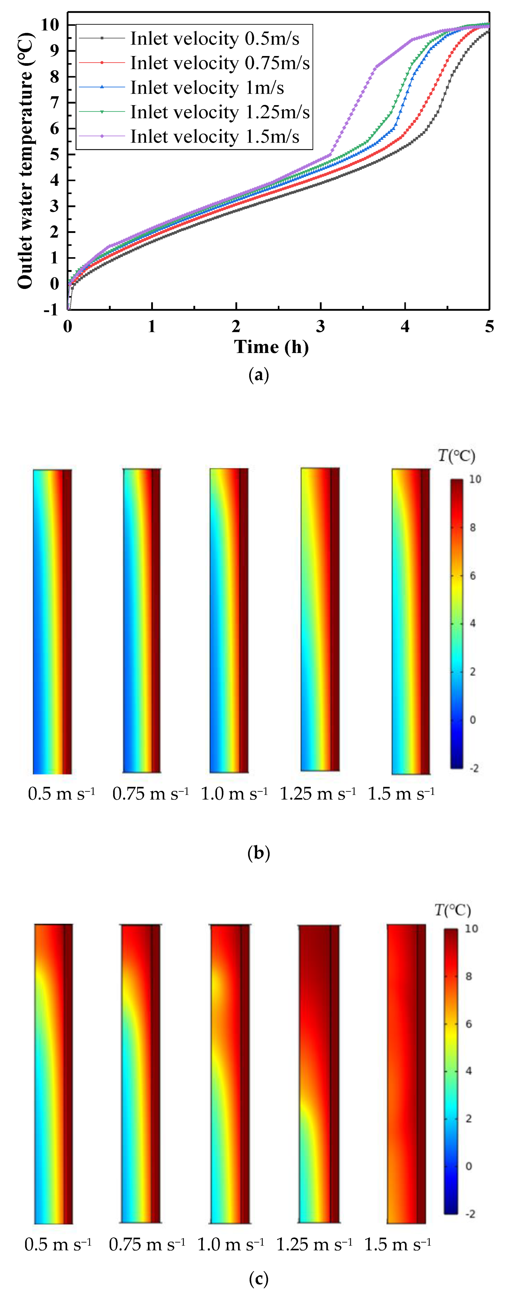
Figure 13a shows the variations of the outlet water temperature with time in the ice melting process under different fed water velocities from the main pipe inlet. With the increase of time, the outlet water temperature under different fed water velocities from the main pipe inlet increases. The outlet water temperature is finally equal to the inlet water temperature of 10 °C after the completion of ice melting. This is because the increased fed water velocity from the main pipe inlet improves the convective heat transfer effect and more heat is supplied to melt the ice during the identical time period, as also can be observed in Figure 13b,c. At the ice melting time of 4 h, the outlet water temperature for fed water velocity from the main pipe inlet of 0.5, 0.75, 1.0, 1.25, and 1.5 m s−1 are 5.3, 5.8, 7.1, 7.9, and 9.2 °C, respectively. To improve the energy effective, the outlet water temperature should be controlled below 7 °C. Therefore, the fed water velocity from the main pipe inlet should be less than 1.5 m s−1.
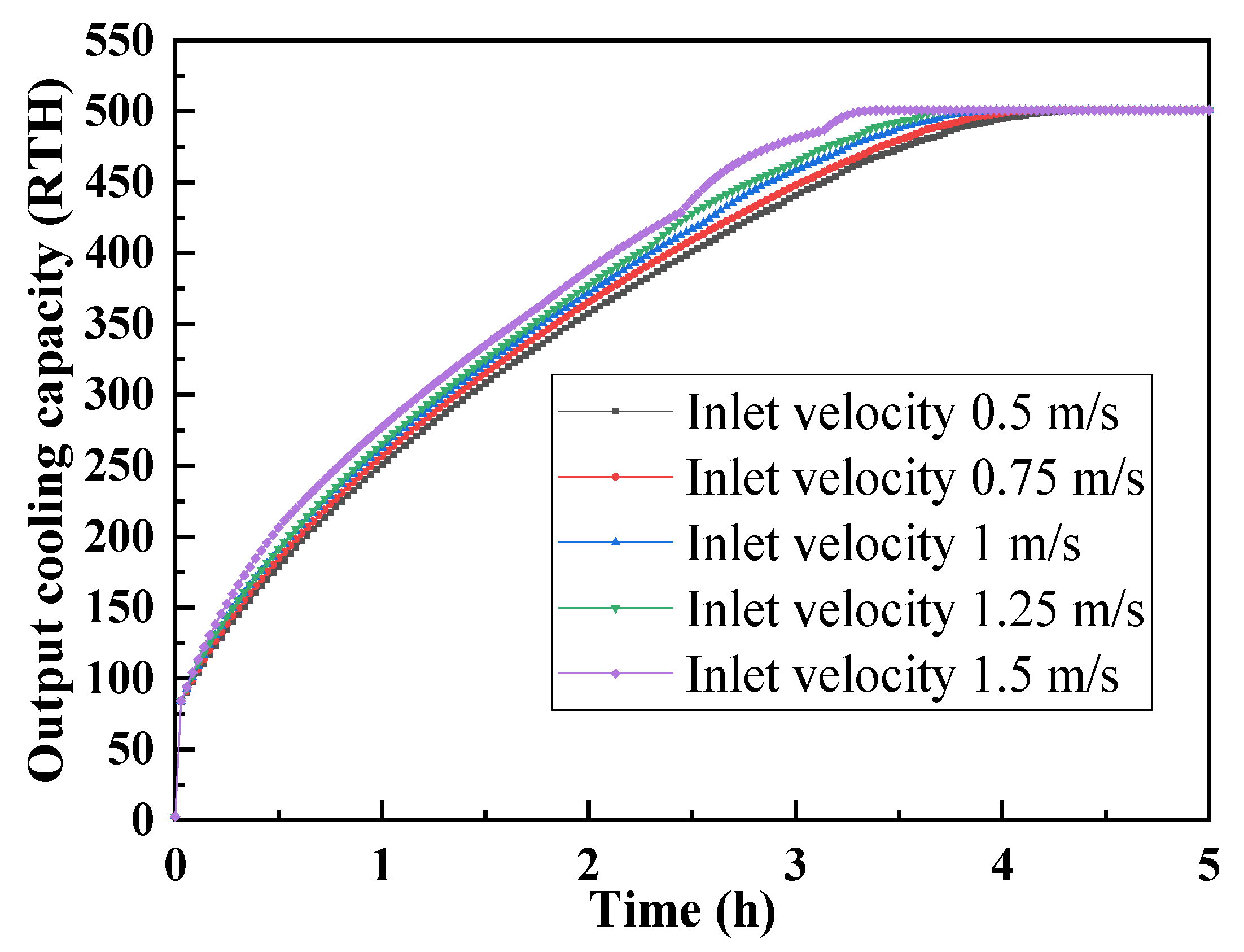
Figure 14 shows the variation of the output cooling capacity for the external ice melting device under different fed water velocities from the main pipe inlet. As the fed water velocity from the main pipe inlet increases, the external ice melting device exhibits a quicker release of output cooling. At 3 h, the total output cooling for the fed water velocity from the main pipe inlet of 0.5, 0.75, 1.0, 1.25, and 1.5 m s−1 are 440, 447, 458, 464, and 481 refrigeration ton per hour (RTH) at the ice melting time of 3 h. Moreover, at the ice melting time of 4 h, all of the total output cooling of 500 RTH can be released when the fed water velocity from the main pipe inlet reaches up to 1.0 m s−1. Based on the discussion above, we can conclude that the water flow velocity of the main pipe of the water diffuser has a great influence on the external ice melting process. Through adjusting the water flow velocity of the main pipe of the water diffuse, different output cooling can be realized to provide fast response speed to the cooling variations in demand by the terminal users.

4. Conclusions

This paper designs a linear multi-pore water diffuser for an ice storage system with 500 t of refrigeration to improve the flow velocity and uniformity of water distribution with a low pipeline pressure drop and a reasonable maximum flow deviation; therefore, enhancing the ice melting efficiency of the external ice melting system. The numerical results show that the diameter of the perforated pore, the number of the pipe rows, and the perforated pores per row has a great impact on the performance of the multi-pore water diffuser. An optimal water diffuser with five rows of trunk pipe with six perforated pores arranged in per row of branch pipe with a diameter of perforated pores of 4 mm, exhibit a relatively lower degree of turbulence and pressure drop. The fed flow velocity from the main pipe inlet exhibits a great impact on the external ice melting process. It is found that the external ice melting process with optimal water diffuser design under flow velocity of 1.0 m s−1 exhibits an enhanced heat transfer rate, a shortened ice melting time, and a low out water temperature compared to the external ice melting process without the water diffuser. Moreover, numerical results also indicate that through adjusting the water flow velocity of the main pipe of the water diffuse, different output cooling different output cooling can be realized, thereby improving response speed of the ice melting system. In next work, we try to employ the manufactured ice melting system to store the cold energy produced by the power grid during the low electricity consumption period (low electricity price level), and releases the cold energy during the daytime peak electricity consumption period (high electricity price level) to provide the air conditioning system, therefore to relieve the pressure on the power grid during the daytime peak period and save cost for the terminal users.

Author Contributions

Conceptualization, L.L. and Y.W. (Yude Wu); methodology, Y.W. (Yude Wu); software, Y.W. (Yude Wu); validation, L.L., Y.L. and X.Y.; formal analysis, X.Y.; investigation, Q.W.; resources, Q.W.; data curation, Q.W.; writing—original draft preparation, X.W.; writing—review and editing, X.Y.; visualization, Y.W. (Yulin Wang); supervision, Y.W. (Yulin Wang); project administration, X.Y.; funding acquisition, X.Y. All authors have read and agreed to the published version of the manuscript.

Funding

This research was funded by [State Grid Corporation Research Project] grant number [5419-202019385A-0-0-00].

Institutional Review Board Statement

Not applicable.

Informed Consent Statement

Not applicable.

Conflicts of Interest

The authors declare no conflict of interest.

Nomenclature

ρ density, kg m−3
μ dynamic viscosity, Pa s−1
P pressure, Pa
u velocity, m s−1
tTime, s
TTemperature, °C
K turbulent kinetic energy
G b turbulent kinetic energy due to buoyancy, J
Gkturbulent kinetic energy due to velocity steps in the bottom laminar flow, J
ε diffusion coefficient
c p specified heat, J kg−1K−1
k thermal conductivity, W m−1 K−1
G b turbulent flow energy
C 1 Constant
C 2 Constant
C 3 Constant
S k Source terms of the equations
S ε Source terms of the equations
C μ 0.09
σ k 1.00
σ ε 1.30
γ w Volume fraction of the liquid phase
gGravity vector, kg s−1
P r t Turbulent energy Prandtl number

References

  1. Saffari, M.; de Gracia, A.; Fernández, C.; Belusko, M.; Boer, D.; Cabeza, L.F. Optimized demand side management (DSM) of peak electricity demand by coupling low temperature thermal energy storage (TES) and solar PV. Appl. Energy 2018, 211, 604–616. [Google Scholar] [CrossRef] [Green Version]
  2. Vetterli, J.; Benz, M. Cost-optimal design of an ice-storage cooling system using mixed-integer linear programming techniques under various electricity tariff schemes. Energy Build. 2012, 49, 226–234. [Google Scholar] [CrossRef]
  3. Rismanchi, B.; Saidur, R.; Masjuki, H.H.; Mahlia, T.M.I. Energetic economic and environmental benefits of utilizing the ice thermal storage systems for office building applications. Energy Build. 2012, 50, 347–354. [Google Scholar] [CrossRef]
  4. Wang, Y.; Wang, X.; Fan, Y.; He, W.; Guan, J.; Wang, X. Numerical Investigation of Tapered Flow Field Configurations for Enhanced Polymer Electrolyte Membrane Fuel Cell Performance. Appl. Energy 2022, 306, 118021. [Google Scholar] [CrossRef]
  5. Wang, Y.; Xu, H.; Wang, X.; Gao, Y.; Su, X.; Qin, Y.; Xing, L. Multi-sub-inlets at cathode flow-field plate for current density homogenization and enhancement of PEM fuel cells in low relative humidity. Energy Convers. Manag. 2022, 252, 115069. [Google Scholar] [CrossRef]
  6. Lizana, J.; Chacartegui, R.; Barrios-Padura, A.; Ortiz, C. Advanced low-carbon energy measures based on thermal energy storage in buildings: A review. Renew. Sustain. Energy Rev. 2018, 82, 3705–3749. [Google Scholar] [CrossRef]
  7. Parra, D.; Swierczynski, M.; Stroe, D.I.; Norman, S.A.; Abdon, A.; Worlitschek, J.; Patel, M.K. An interdisciplinary review of energy storage for communities: Challenges and perspectives. Renew. Sustain. Energy Rev. 2017, 79, 730–749. [Google Scholar] [CrossRef]
  8. Wang, S.; Jin, L.; Han, Z.; Li, Y.; Ou, S.; Gao, N.; Huang, Z. Discharging performance of a forced-circulation ice thermal storage system for a permanent refuge chamber in an underground mine. Appl. Therm. Eng. 2017, 110, 703–709. [Google Scholar] [CrossRef]
  9. Carbonell, D.; Philippen, D.; Haller, M.Y.; Brunold, S. Modeling of an ice storage buried in the ground for solar heating applications. Validations with one year of monitored data from a pilot plant. Sol. Energy 2016, 125, 398–414. [Google Scholar] [CrossRef]
  10. Ge, M.; Li, Z.; Wang, Y.; Zhao, Y.; Zhu, Y.; Wang, S.; Liu, L. Experimental study on thermoelectric power generation based on cryogenic liquid cold energy. Energy 2021, 220, 119746. [Google Scholar] [CrossRef]
  11. Korti, A.I.N. Numerical heat flux simulations on double-pass solar collector with PCM spheres media. Int. J. Air-Cond. Refrig. 2016, 24, 1650010. [Google Scholar] [CrossRef]
  12. Zhao, Y.; Fan, Y.; Li, W.; Li, Y.; Ge, M.; Xie, L. Experimental investigation of heat pipe thermoelectric generator. Energy Convers. Manag. 2022, 252, 115123. [Google Scholar] [CrossRef]
  13. Bi, Y.; Yu, M.; Wang, H.; Huang, J.; Lyu, T. Experimental investigation of ice melting system with open and closed ice-storage tanks combined internal and external ice melting processes. Energy Build. 2019, 194, 12–20. [Google Scholar] [CrossRef]
  14. Karim, M.A. Experimental investigation of a stratified chilled-water thermal storage system. Appl. Therm. Eng. 2011, 31, 1853–1860. [Google Scholar] [CrossRef]
  15. Wildin, M.W. Performance of stratified vertical cylindrical thermal storage tanks, part I: Scalemodel tank; Part II: Prototype tank. ASHRAE Trans. 1989, 5. [Google Scholar]
  16. Jirka, G.H.; Harleman, D.R. The Mechanics of Submerged Multiport Diffusers for Bouyant Discharges in Shallow Water; MIT Energy Lab: Cambridge, MA, USA, 1973. [Google Scholar]
  17. Abessi, O.; Roberts, P.J. Multiport diffusers for dense discharge in flowing ambient water. J. Hydraul. Eng. 2017, 143, 04017003. [Google Scholar] [CrossRef]
  18. Rawn, A.M.; Bowerman, F.R.; Brooks, N.H. Diffusers for disposal of sewage in sea water. Trans. Am. Soc. Civ. Eng. 1961, 126, 344–384. [Google Scholar] [CrossRef]
  19. Tang, J.; OuYang, Z.; Shi, Y. Diffuser design and experimental research of a large-scale chilled water storage system. Energy Sources Part A Recovery Util. Environ. Eff. 2021, 43, 1456–1467. [Google Scholar] [CrossRef]
  20. Ling, J.; Zhao, Y.; Xing, J.; Bai, J. Research on slotted-pipe diffuser of naturally stratified water-storage tank. In Proceedings of the 2011 International Conference on Electric Technology and Civil Engineering (ICETCE), Lushan, China, 22–24 April 2011; pp. 3425–3428. [Google Scholar]
  21. Chung, J.D.; Cho, S.H.; Tae, C.S.; Yoo, H. The effect of diffuser configuration on thermal stratification in a rectangular storage tank. Renew. Energy 2008, 33, 2236–2245. [Google Scholar] [CrossRef]
  22. Karim, M.A. Performance evaluation of a stratified chilled-water thermal storage system. World Acad. Sci. Eng. Technol. 2009, 53, 326–334. [Google Scholar]
  23. Song, J.; Bahnfleth, W.P.; Cimbala, J.M. Parametric study of single-pipe diffusers in stratified chilled water storage tanks (RP-1185). HVACR Res. 2004, 10, 345–365. [Google Scholar] [CrossRef]
  24. Cui, Y.; Xia, R.; Kong, Y. Modelling and structure optimisation on throttle tube of pre-throttle water distributor. Int. J. Model. Identif. Control 2020, 36, 248–255. [Google Scholar] [CrossRef]
  25. Cui, Y.; Kong, Y.; Xia, R. Modelling and experimental study on hierarchical throttling water distributor. Int. J. Model. Identif. Control 2020, 36, 126–135. [Google Scholar] [CrossRef]
  26. Tang, J.; Shi, Y.; OuYang, Z. Optimization design of the octagonal water diffuser with uniform flow orifice plate. J. Energy Storage 2021, 44, 103374. [Google Scholar] [CrossRef]
  27. Zachár, A. Investigation of a new tube-in-tube helical flow distributor design to improve temperature stratification inside hot water storage tanks operated with coiled-tube heat exchangers. Int. J. Heat Mass Transf. 2013, 63, 150–161. [Google Scholar] [CrossRef]
  28. Jia, D.; Pei, X.; Liu, H.; Sun, F. Research on the flow control strategy of water distributor in Water Injection Well. In Proceedings of the 33rd Chinese Control Conference, Nanjing, China, 28–30 July 2014; pp. 4993–4996. [Google Scholar]
  29. Kopparthy, S.; Mansour, M.; Janiga, G.; Thévenin, D. Numerical investigations of turbulent single-phase and two-phase flows in a diffuser. Int. J. Multiph. Flow 2020, 130, 103333. [Google Scholar] [CrossRef]
  30. Bleninger, T.; Perez, L.M.; Milli, H.; Jirka, G.H. Internal hydraulic design of a long diffuser in shallow water: Buenos Aires sewage disposal in Rio de la Plata estuary. Proc. XXXI IAHR Congr. 2005, 219–220. Available online: http://www.koreascience.or.kr/article/CFKO200507523367703.page?&lang=en (accessed on 20 January 2022).
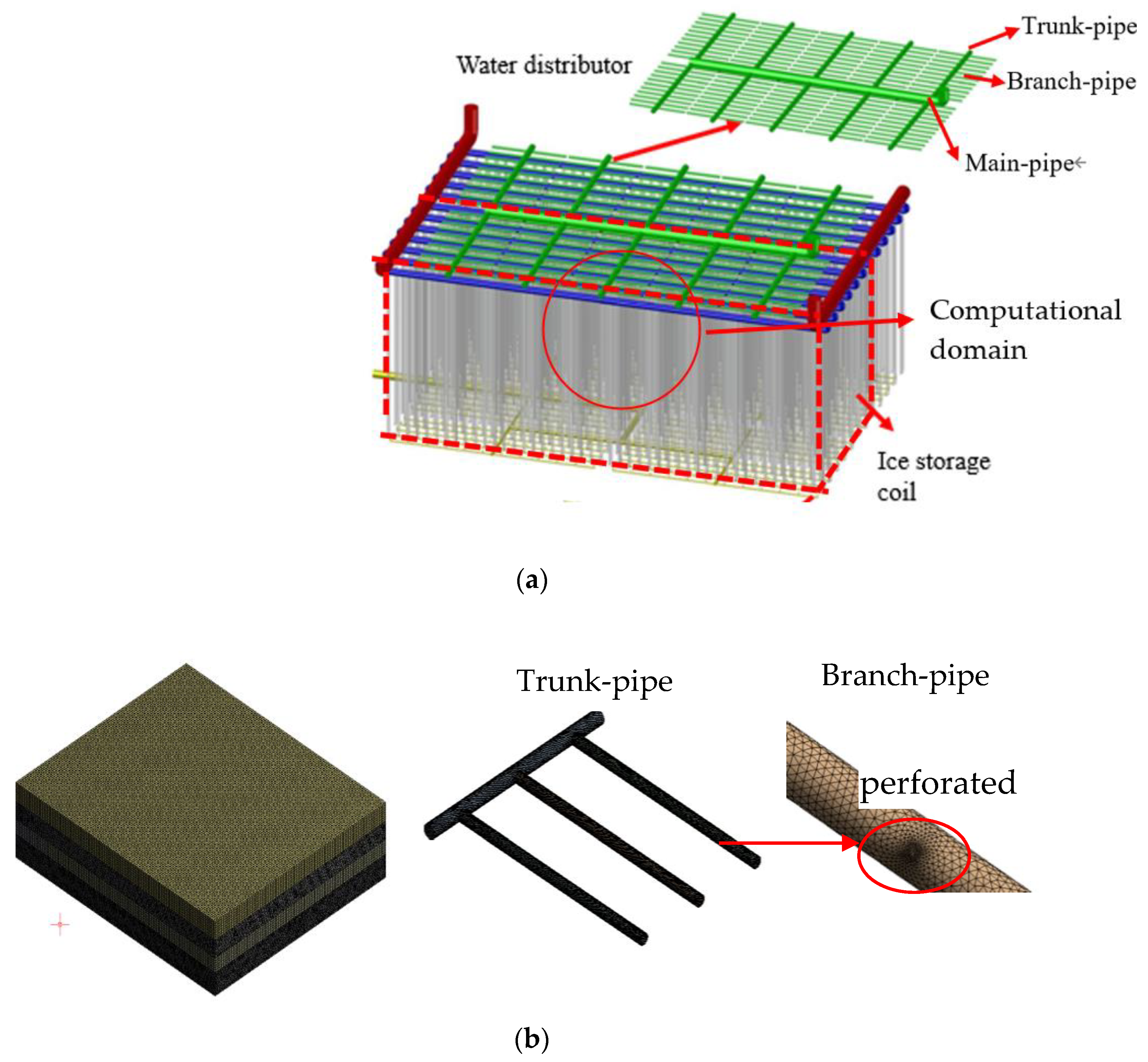
Figure 1. (a) Schematic diagram and computational domain of the external ice melting device with a water diffuser and (b) the generated grid.
Energies 15 02181 g001
Figure 2. (a) Distribution of the velocity at the middle x–y plane of the branch pipe with a typical number of three trunk pipe rows and (b) average velocity and degree of the turbulence for the water diffuser under different numbers of trunk pipe rows.
Energies 15 02181 g002
Figure 3. Maximum flow deviation for the water diffuser under different number of trunk pipe rows.
Energies 15 02181 g003
Figure 4. Maximum pressure drop within the water diffuser and average velocity of the perforated pore under different number of trunk pipe rows.
Energies 15 02181 g004
Figure 5. (a) Distribution of the velocity at the middle x–y plane of the branch pipe and (b) the average velocity and degree of the turbulence for the water diffuser under different numbers of perforated pores.
Energies 15 02181 g005aEnergies 15 02181 g005b
Figure 6. Maximum flow deviation for the water diffuser under different numbers of perforated pores.
Energies 15 02181 g006
Figure 7. Maximum pressure drop within the water diffuser and average velocity of perforated pores under different numbers of perforated pores.
Energies 15 02181 g007
Figure 8. (a) Distribution of the velocity at the middle x–y plane of the branch pipe and (b) the average velocity and degree of the turbulence for the water diffuser under different perforated pore diameters.
Energies 15 02181 g008
Figure 9. Maximum flow deviation for water diffuser under different perforated pore diameters.
Energies 15 02181 g009
Figure 10. Maximum pressure drop within the water diffuser and the average velocity of perforated pores under different perforated pore diameters.
Energies 15 02181 g010
Figure 11. Computational domain of a 2D half-cell of the U-shaped coil and the divided mesh.
Energies 15 02181 g011
Figure 12. Curves for the variations of ice storage fraction with the time in the ice melting process under different fed water velocity from the main pipe inlet (a) with static ice melting and (b) without ice melting.
Energies 15 02181 g012aEnergies 15 02181 g012b
Figure 13. (a) Variations of the outlet water temperature with time in the ice melting process. Profile of the outlet water temperature (b) at 2.5 h and (c) 3.0 h under different fed water velocities from the main pipe inlet.
Energies 15 02181 g013
Figure 14. Variation of the output cooling capacity for the external ice melting device under different fed water velocities from the main pipe inlet.
Energies 15 02181 g014
Table 1. Boundary conditions for two-phase water diffuser model.
DescriptionBoundary Conditions
Wall No slip
Main pipe inlet1.0 m/s
Return water outletPressure outlet
Table 2. Parameters of different water diffuser designs.
Design NumberNumber of Trunk PipesPerforated Pore Diameter (mm)Number of Perforated Pores
1346
2446
3546
4646
5746
6544
7545
8547
9548
10566
11586
125106
Note: the number of branch pipe are fixed at 11 due to the structure of the coil.
Table 3. Thermophysical property of water and ice in this model.
DescriptionTemperature
(°C)
Density
(Kg m−3)
Specific Heat (KJ (kg K)−1)Thermal Conductivity (W (m K)−1)Kinematic Viscosity (m2 s−1)
Liquid water10999.74.1910.5740.000001306
Ice09172.0972.1--
Table 4. Relationship between the fed water velocity from the main pipe inlet and the velocity of the water distribution.
Director Inlet Velocity v 1 ( m   s 1 ) Calculation FormulaNumerical Simulation Velocity v 2 ( m   s 1 )
0.5 π r 2 × v 1 = S 1 × v 2 0.016
0.75 π r 2 × v 1 = S 1 × v 3 0.024
1 π r 2 × v 1 = S 1 × v 4 0.032
1.25 π r 2 × v 1 = S 1 × v 5 0.04
1.5 π r 2 × v 1 = S 1 × v 6 0.048
Publisher’s Note: MDPI stays neutral with regard to jurisdictional claims in published maps and institutional affiliations.