Article

Research on the Intake Port of a Uniflow Scavenging GDI Opposed-Piston Two-Stroke Engine

1
Ningbo Institute of Materials Technology and Engineering, Chinese Academy of Sciences, Ningbo 315201, China
2
University of Chinese Academy of Sciences, Beijing 100049, China
3
Zhejiang Key Laboratory of Robotics and Intelligent Manufacturing Equipment Technology, Chinese Academy of Sciences, Ningbo 315201, China
4
School of Engineering, University of Birmingham, Birmingham B15 2TT, UK
5
School of Mechanical Engineering, Nanjing University of Science and Technology, Nanjing 210094, China
*
Author to whom correspondence should be addressed.
Energies 2022, 15(6), 2148; https://doi.org/10.3390/en15062148
Submission received: 10 February 2022 / Revised: 2 March 2022 / Accepted: 11 March 2022 / Published: 15 March 2022

Abstract

:
The intake port structure optimization is very important for the uniflow scavenging opposed-piston two-stroke engine, as the intake port structure affects the scavenging efficiency and turbulence kinetic energy and thus further impacts the engine indicated efficiency. This paper aims at improving the indicated efficiency, presenting a comprehensive study on the intake port optimization concerning both scavenging efficiency and turbulence kinetic energy. First, a three-dimensional model based on computational fluids dynamics is established and validated. Subsequently, different numbers of intake ports are compared and analyzed from the perspectives of the scavenging efficiency and turbulence kinetic energy. Furthermore, the double-ports intake structure is selected with the consideration of the compact structure and high scavenging efficiency. Then, the radial angle and width of the double-ports structure are optimized based on the response surface method. The results show that the optimized structure increases the turbulence kinetic energy in relative high scavenging efficiency. The indicated efficiency exhibits a significant increase within the speed range of 1000–4000 rpm and reaches the maximum value of 39.5% around 2000 rpm.

1. Introduction

The opposed piston two-stroke (OP2S) engine has two opposed reciprocated pistons in one cylinder. Because of the compact structure, it has the advantages of high power density, low heat loss, and good performance on noise, vibration, and harshness (NVH) [1,2]. Thus, the OP2S engine aroused intensive studies in the applications such as range-extended vehicles [3,4,5,6], military vehicles [7,8,9], and small aircraft [10]. Previously, owing to the strict regulation of emission, the application of the OP2S engine was restricted. Fortunately, recent studies have shown that advanced combustion technology including blend alternative fuels [11,12], Partially Premixed Combustion [13], gasoline direct injection (GDI), and dual fuel [14] can drastically improve engine performance. Among those advanced combustion technologies, GDI is an ideal technical scheme in a short period. Compared to the single-cylinder two-stroke engines with port fuel injection, the GDI OP2S engine reduces the fuel short circuit loss in the scavenging process and improves the engine performance [15]. In terms of high engine performance, high scavenging efficiency and intensive turbulence [16,17] are two key factors. Those parameters can make the injected fuel mix homogeneously and increase the velocity of flame propagation as well.
However, it is hard to obtain high scavenging efficiency and intensive turbulence simultaneously in a uniflow scavenging OP2S engine whose tumble flow is hard to establish in the cylinder. To obtain high engine performance, intake port structure analysis and optimization of the OP2S engine are necessary as they determine the organization of the intake airflow pattern.
In the previous literature, the analysis of the intake port structure mainly focused on its size, radial/axial angle, height, and width. The Achates Power researchers designed different port sizes for various applications [18]. They indicated that a small size intake port is suitable for low speed range engines, and the big one is suitable for high power density applications. In Changming He’s research [19], different axle angles of the intake port are studied to improve the scavenging efficiency. It is reported that an improvement of up to 12% was realized with the proper combination of axle angle and port timing. Zhenyu Zhang [20] and Yining Wu [21] studied the effects of the radial angle and width on scavenging efficiency. Both of their studies indicated that the radial angle helps to form the swirl flow. It makes the residual gas spread around the cylinder axis, which helps realize the stratified charge of the fresh air. With the optimized radial angle and width, the maximum scavenging efficiency of their prototype could reach 90.7% and 93% respectively. Those structural parameters can effectively improve high scavenging performance. However, high engine performance is not only determined by high scavenging efficiency but also by the turbulence kinetic energy (TKE). Previous studies have shown that TKE has positive effects on flame propagation and thus could improve the indicated efficiency [22,23]. For the OP2S engine, Fukang Ma designed different shapes of the piston crown [24]. With this method, the intake airflow is squeezed to form intensive turbulence during the ignition process. Nevertheless, adjusting the structural parameters of the OP2S engine easily affected the distribution of residual gas and thus reduced scavenging efficiency. Therefore, analyzing the structure of the intake port, which concerns uniflow scavenging and the TKE performance simultaneously, is necessary for improving the engine performance.
After the structural analysis, modeling and optimization of the intake port structure parameters are vital. By establishing a mono-dimensional (1D) model, Heyang Ma came up with a multi-objective optimization method to evaluate and optimize the scavenging process [25]. However, such a model cannot reflect the transient airflow characteristic and thus could not optimize the scavenging efficiency and turbulence kinetic energy simultaneously. Based on CFD, Fukang Ma presented a global optimization for the intake port structure concerning the indicated mean effective pressure by using an orthogonal experimental method [26,27]. However, the orthogonal experimental method relies on the subjectively selected weight and boundaries. In recent works, the response surface model developed by a backpropagation neural network (BPNN) model is suitable for such a non-linear problem [28,29,30] and is widely used in engine structure optimization [31,32,33].
Therefore, to obtain high scavenging efficiency and high TKE simultaneously in a uniflow scavenging OP2S engine whose tumble flow is hard to establish, this paper studied the influence of the intake port structure on the in-cylinder airflow and proposed a double-ports intake structure. Whereafter, the intake radial angle and width are optimized globally. The optimized structure has improved the TKE under high scavenging efficiency and thus has improved the indicated efficiency drastically. The paper is organized as follows: first, the prototype configuration and its working principle are introduced. Subsequently, the CFD model of the prototype is established and validated. Then, using the CFD model, the airflow motions in four intake structure configurations with different intake port numbers are analyzed. From this, the double-ports intake structure is proposed with the consideration of high scavenging efficiency and compact structure. Next, the intake port radial angle (IPRA) and intake port width (IPW) of the proposed structure are optimized using a response surface model. Finally, the working characteristic of the optimized structure is analyzed in detail under different engine speeds.

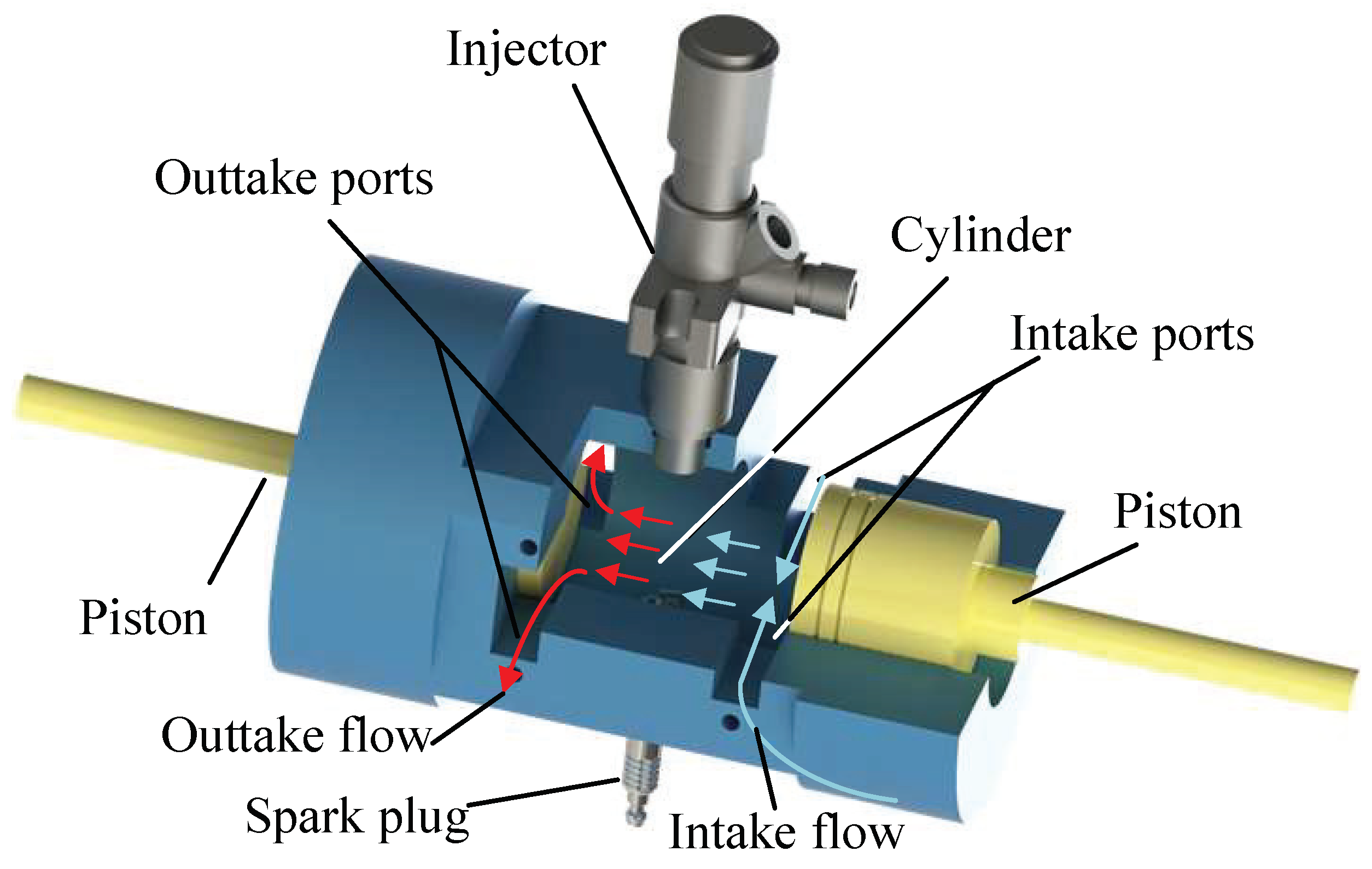
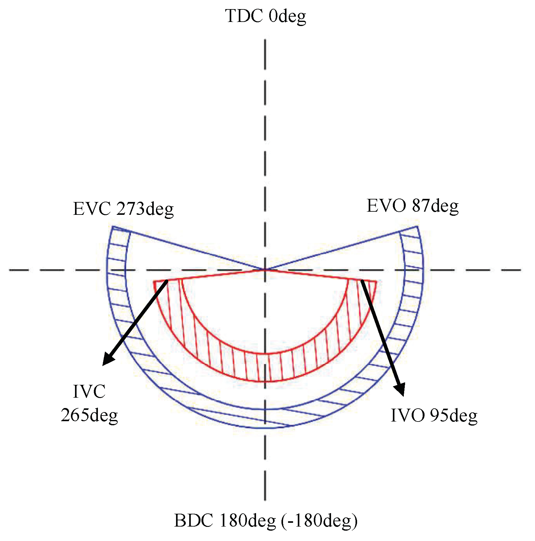
2. OP2S Configuration and Working Principle

As shown in Figure 1, the proposed OP2S engine consists of a GDI injector, a spark plug, two opposed pistons, and a cylinder. The GDI injector and the spark plug are mounted vertically alongside the center plane of the cylinder. The opposed two pistons are arranged horizontally and linearly in the same cylinder, and their momentum can be eliminated dynamically during the reciprocating motion. In the cylinder wall, the intake and outtake ports are opened based on the designed port timing. The main parameters of this engine are listed in Table 1.
During the working conditions, the spark plug ignites the compressed combustible mixture when the opposed pistons of the OP2S engine are close to their top dead centers (TDC). Compared with the single-cylinder engine, OP2S offers a faster expansion characteristic and thus reduces the heat loss in the top dead center. Afterward, the piston opens the intake and exhaust ports during the expansion stroke to complete the scavenging process. Driven by crankshaft mechanisms, the opposed pistons move up to the top dead centers again. In this stroke, the inlet and exhaust valves are closed and the combustible mixture is compressed and ignited again. Such a period would be carried out cycle by cycle.
As is shown in Figure 1, the port-to-port uniflow scavenging is applied in the proposed engine. For high scavenging efficiency and TKE, different intake port structure parameters need to be analyzed and optimized comprehensively. A CFD model is established first to have a detailed study for such a transient, three-dimensional in-cylinder airflow.

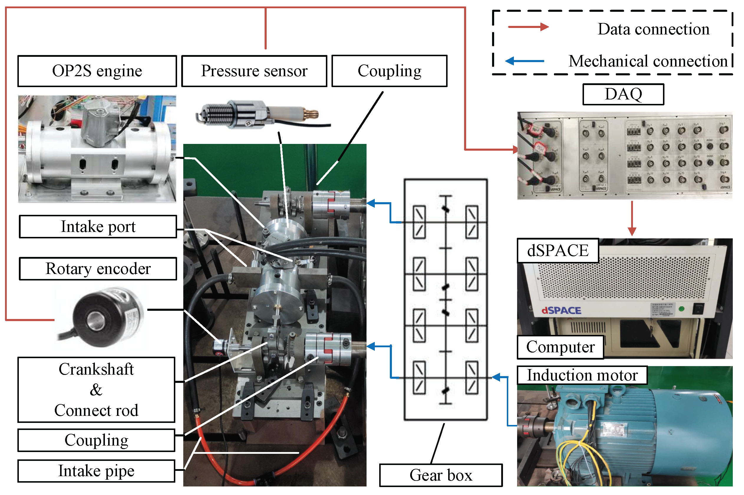
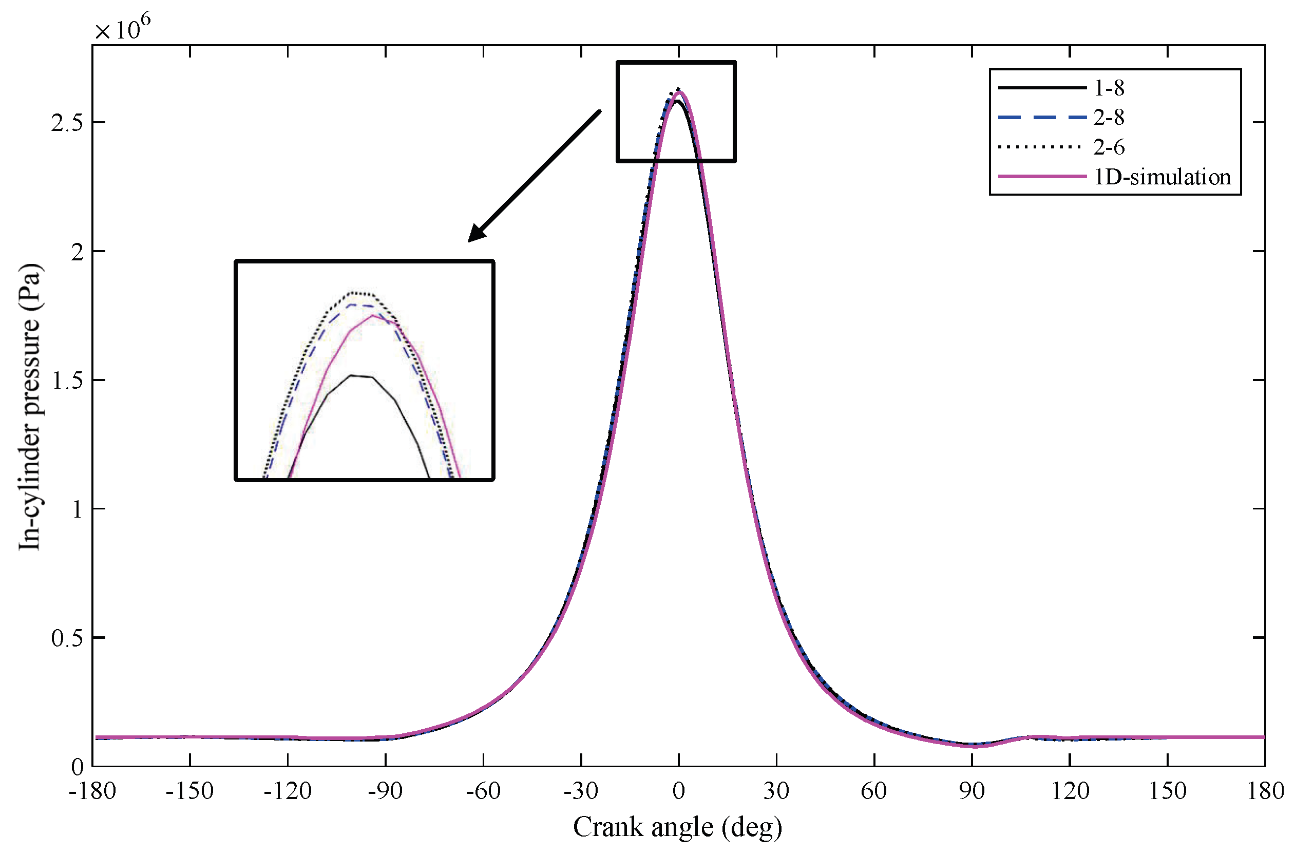
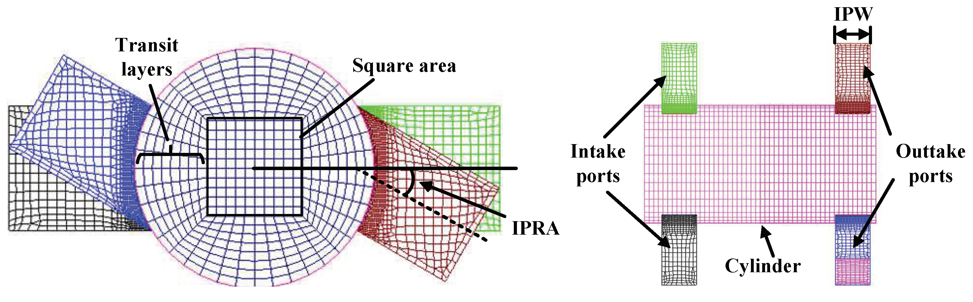
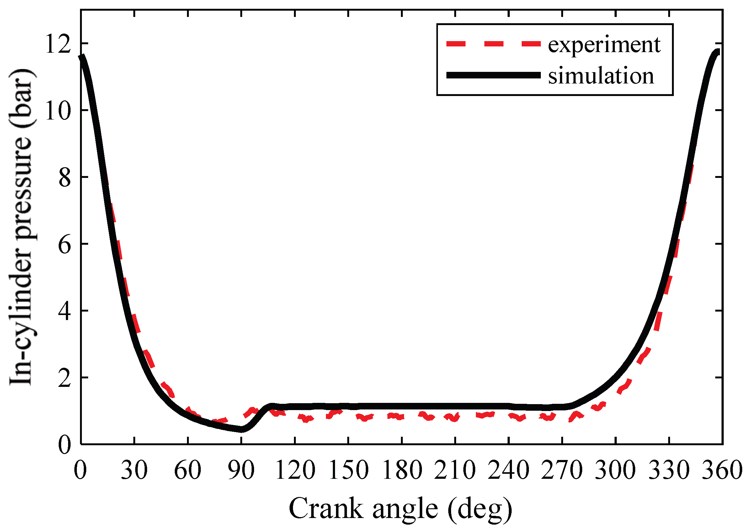
3. CFD Modeling and Validation

In this paper, AVL/FIRE is used to establish the CFD numerical model of OP2S for the in-cylinder air-flow and combustion process. In this model, meshing, initial conditions, and solving models are developed sequentially.
Based on the structural characteristics of the OP2S engine in Figure 2, the meshings of three calculation domains are considered: the cylinder, the intake port, and the outtake port. In the cylinder, a meshing method including square and transition area is adopted for an accurate result: A square area is firstly defined and then gradually transits to the circle, as shown in Figure 2. In addition, the shapes of intake ports and outtake ports are both nearly rectangular, thus it is easy to make a hexahedral mesh in AVL fire pre-processing code. As for the mesh size, the main parameters that need to be determined are the length of the sizes of the square and the number of layers needed for the transition. The expression is defined as “a-b ”, where a refers to the length of the sides of the square (dm), and b refers to the layers of the transition. Three different types of combinations, 1–8, 2–8, and 2–6, will be analyzed in the following.
To obtain the initial boundary condition, a test platform of the OP2S engine is designed and implemented. As shown in Figure 3, this platform includes four main parts: OP2S engine, gearbox, driving motor, and signal acquisition system. A gearbox consisting of four meshing gears helps to realize the opposite motion of the opposed pistons of the OP2S engine synchronously. An induction motor, controlling the engine speed, is used as the driving motor. The signal acquisition system consists of sensors, dSPACE, and an industrial personal computer. From the test platform and experimental results, some initial boundary conditions such as the initial in-cylinder pressure, the intake pressure, and temperature, as well as the outtake pressure, are obtained. Those physical signals are used to build and verify the 1D model in AVL-boost. The in-cylinder pressure curve is shown in Figure 4 Then, based on the verified 1D model, initial boundary conditions of the CFD model of the OP2S engine are given as listed in Table 2.
In the CFD model, the k-zeta-f modeln [34] is selected to simulate the turbulence motion. Previous literature has proved that it is effective in different flow fields such as combustion, two-phase flow, and heat transfer [35]. For the fuel injection process, the Taylor Analogy Breakup (TAB) model is chosen for the simulation of liquid plumes break-up phenomena, which is in good agreement with the injector used in the experiment [36]. Besides, the walljet1 model is used to simulate the impingement of sprays on walls because it is suitable for the heated walls [37]. The extended coherent flame model (ECFM) is selected to simulate the combustion process of the GDI engine because it can be used in the homogeneous and inhomogeneous charges [38,39]. Finally, as listed in Table 3, the established CFD model includes the k-zeta-f model, TAB model, and ECFM model.
After completing the basic flow of modeling, the different combinations of mesh sizes are calculated and compared with the 1D simulation results, as shown in Figure 4. All those combinations show good convergence. For the consideration of calculation time and accuracy, the mesh size with the combination of 2–8 is selected. Besides, Figure 5 also demonstrates that the 1D simulation results have good agreement with the CFD model.
The established and validated CFD model ensures the accuracy in the following simulations and optimization. Using this model, the influence of intake port number and shapes on the scavenging efficiency and TKE will be presented as follows.

4. Simulation and Optimization Results and Discussion

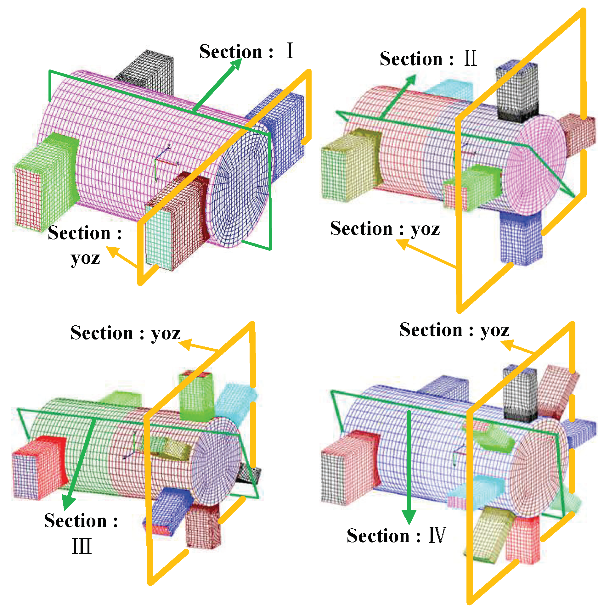
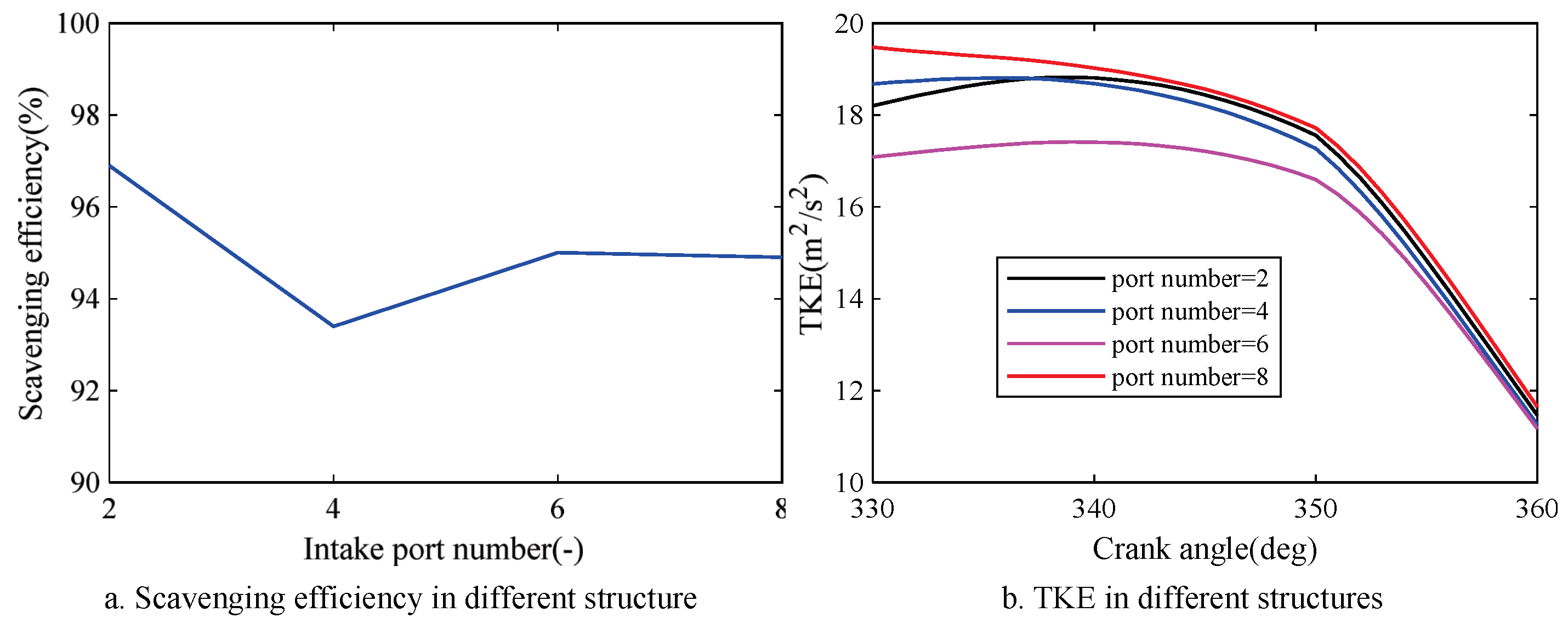
4.1. Study on the Influence of Intake Port Number

In this paper, the intake section area is 312 mm2. In order not to change the port opening time, when comparing the effects of the intake port numbers, the intake port width is set to the same value. The pistons open the outtake port first at 87 crank angle degrees (CAD) and close it in 273 CAD. The intake port is opened at 95 CAD and closed at 265 CAD. The port opening time diagram is shown in Figure 6.
There are four different types of intake port numbers compared in this paper. They are 2, 4, 6, and 8 respectively. To make a detailed study, two types of sections are created to illustrate the in-cylinder airflow motion and residual gas fraction.
Figure 7 demonstrates the section place. In the figure, Sections I to IV represent the area through the entire cylinder from its center. Those sections pass through two adjacent intake ports to reflect the interaction between two intake airflows. The yoz section stands for the area that crosses all the intake ports in the middle. This section shows the interaction among all intake airflows. The velocity of each section is demonstrated in Figure 8. It should be noted that the crank angle of 240 deg is selected to compare the airflow velocity because the intake port is about to close under this crank angle. Furthermore, the in-cylinder airflow shows representative characteristics.
In Figure 8, Section I indicates that the double-ports intake structure shows ideal uniflow scavenging characteristics. All the intake airflow directly flows to the outtake ports without any vortex or reverse flow. This means that the fresh air charges the cylinder sufficiently and totally. While, as the number of intake ports increases, the vortex appears partly in the cylinder. In Section II, two large circular vortexes with round edges appear in the top and bottom of the section near the outtake port. Section III and IV demonstrate that two spindly vortexes form in the top and bottom part of the section between the intake and outtake ports. The vortex leads to the residual gas “trapped” in such areas, so the cylinder cannot be charged totally.
Besides, the yoz section also indicates that with the increase of intake port number, flow interference becomes more intensive. Such an interference also causes the reduction of the intake energy, resulting in a low speed of scavenging movement direction in the center of the cylinder (as is shown in Sections I to IV, the velocity magnitudes drop with the increase of intake port number). The low scavenging speed influences the scavenging efficiency as well. As a result of the vortexes and interferences, the distribution of the residual gas is shown in Figure 9. In the figure, the red part stands for high EGR, which means quantities of residual gas gathering in such an area, and that leads to the decline of the scavenging efficiency.
Figure 10 shows the change of scavenging efficiency and TKE in the structures with different intake port numbers. From Figure 10a, the double ports structure has the highest scavenging efficiency (96.8%), while that with four ports presents the lowest. The six ports structure and eight ports structure have a similar scavenging efficiency (95% and 94.9% respectively). In a word, the scavenging efficiency declines first when the intake port number increases from 2 to 4. Then it presents a slight increase and finally stabilizes around 95%. Figure 10b shows that in the potential ignition period (340–360 CAD), TKE presents the same value. This means under the same intake port section area, the intake port number has little effect on the TKE during the ignition period but a relatively high impact on the scavenging efficiency. Considering the final scavenging efficiency and TKE, the double-ports intake structure is selected.

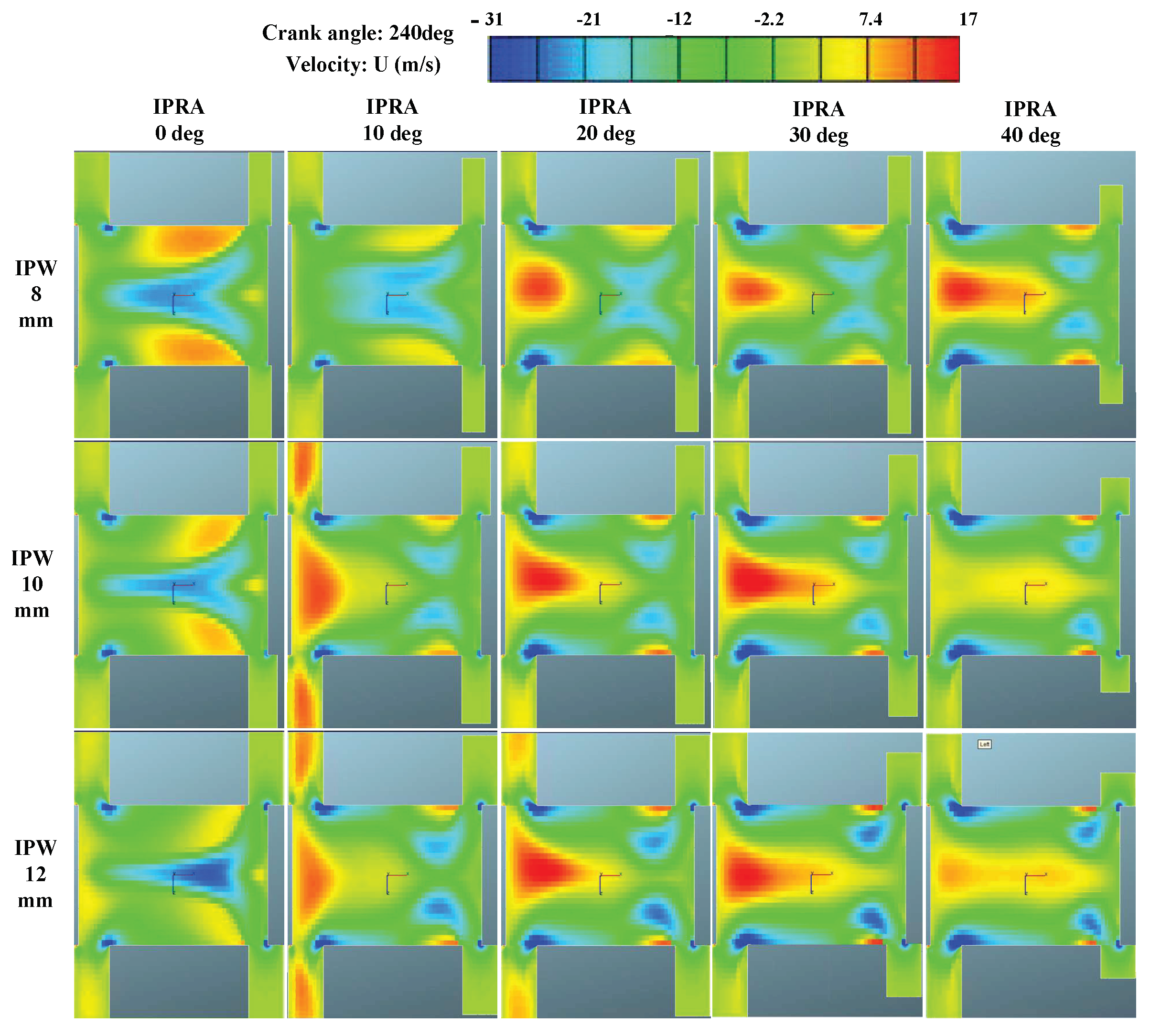
4.2. Optimization for the IPRA and IPW

From the description given above, the final CFD simulation results under different IPRA and IPW are given in Figure 11. The section shown in the figure is horizontally alongside the intake port through the cylinder center. Because of the same reason described above, the crank angle degree is chosen as 240 deg.
In the figure, different color stands for the velocity along the cylinder axis. The blue part stands for the velocity in the same direction as the scavenging. While the red one means the velocity against the scavenging direction. In Figure 11, the increase of IPW strengthens the scavenging airflow motion near the intake port. While in most cases, that on the central part of the cylinder is weakened. As for the IPRA, the velocity distribution varies from different IPW. When the IPW is 8 mm, the airflow motion in the central part of the cylinder presents a trend of anti-scavenging as the IPRA increases. When the IPW is 10 mm and 12 mm, such a trend shows a decline in the high IPRA condition.
Because of the high pressure in the intake port, the residual gas in the cylinder cannot flow into the inlet pipe. Therefore, the reverse airflow in the cylinder prevents the exhaust gas from being discharged. Thus, the exhaust gas ratio in that place is higher than in other parts. This also corresponds to the distribution of residual gas fraction in EGR. Take three cases as an example; when the IPRA is 0 deg, the residual gas distribution in the cylinder is shown in Figure 12. As is described before, the increase of IPW strengthens the scavenging flow on edge of the cylinder. Therefore, in Figure 11, when the crank angle reaches 240 deg, less exhaust gas can be seen on the edge of the cylinder.
Figure 12 also demonstrates a typical distribution of the residual gas fraction in the cylinder in one cycle. At 87 crank angle degrees (CAD), the outtake ports open. The residual gas in the cylinder is pushed into the outtake ports, resulting in the decline of the in-cylinder pressure. However, because no fresh air is charged into the cylinder, the EGR remains to be 1 (as is shown in the figure, the cylinder is totally red). Later, at 95 CAD, the intake ports opened. Driven by the pressure difference between the intake ports and the cylinder, the fresh gas is charged into the cylinder, resulting in the decline of the residual gas fraction of the cylinder.
Using the backpropagation neural network (BPNN), the response surface of the IPRA and IPW is obtained and shown in Figure 13. The BPNN is trained and tested by the CFD simulation results. Then, using the response surface, the optimization function of IPRA and IPW is shown as follows:
M a x T K E = f I P R A , I P W s . t . S c a v e . E f f i 0.96 8 I P R A 14 0 I P R A 45
The optimized IPRA and IPW are 3 deg and 10 mm respectively. Then the results are brought back to the established CFD model for verification. The calculation errors of the maximum TKE and scavenging efficiency are less than 8.8% and 0.1% respectively, which indicates that the optimization results are reliable.

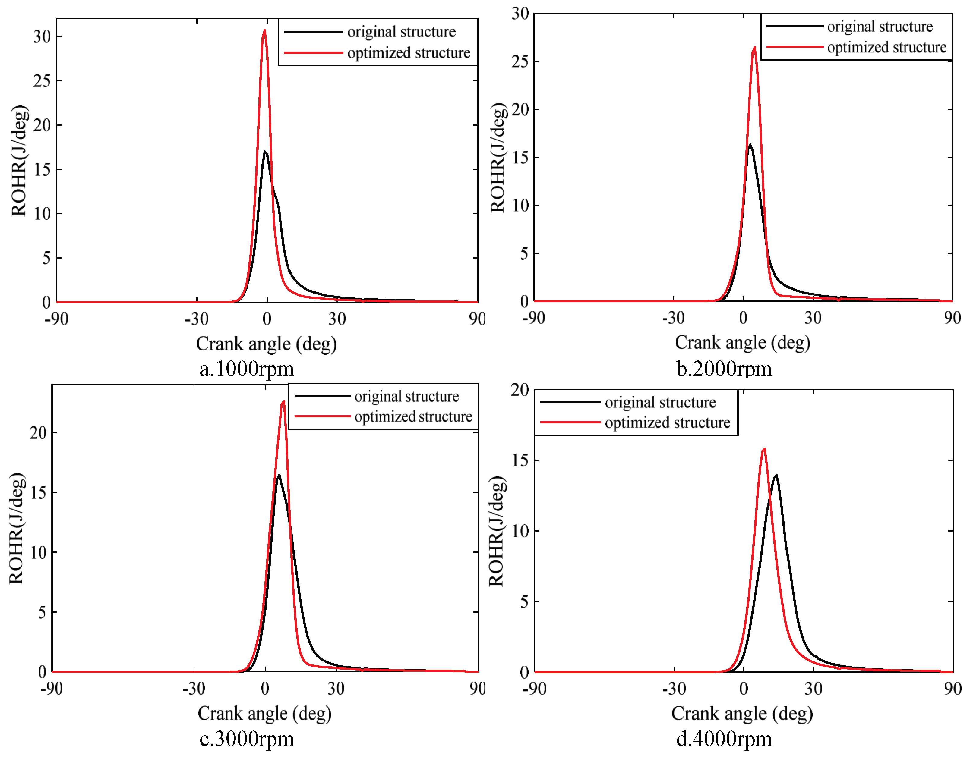
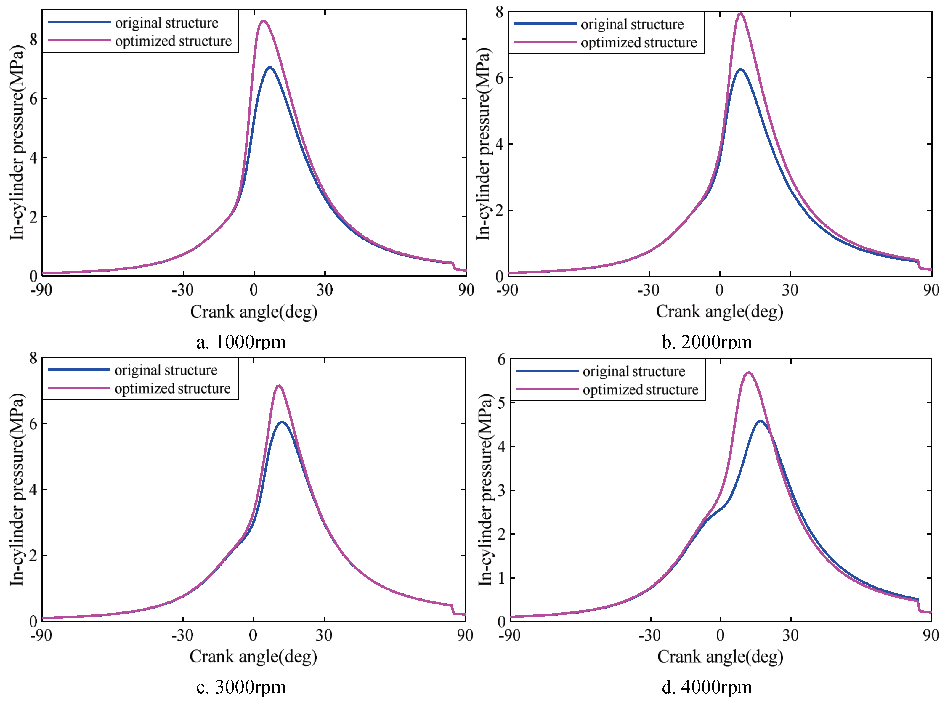
4.3. Working Characteristics Analysis of the Optimized Structure

In this section, the working characteristics of the optimized structure are analyzed under different operating speeds. Considering the speed range of the range extender is usually under 4000 rpm, the working characteristics within the range of 1000–4000 rpm are presented in Figure 14.
Figure 14a,b show that even though the scavenging efficiency shows little decline (less than 1%), a significant increase (over 15%) of TKE is presented as well. Besides, most of the scavenging efficiency is over 90% in the optimized structure when the engine speed is under 4000 rpm. As a result of improving the TKE with little decrease of the scavenging efficiency, significant increase of the indicated efficiency is demonstrated in Figure 14c. To give a detailed study of the working characteristics, the combustion equivalence ratio is shown in Figure 15.
In Figure 15, the section is located in the center of the cylinder across the spark plug. According to the figure, the injected fuel distributes more homogeneously in the optimized structure. This is because the optimized structure makes the turbulence more intensive in the cylinder. The intensive turbulence spreads the fuel over a wider area of the cylinder, which benefits the flame propagation. To be more specific, the rate of heat release (ROHR) is shown in Figure 16.
Within the operating speed range, the heat release ratio increases more drastically, especially in 1000 rpm and 2000 rpm. The ROHR in the optimized structure also obtains a higher peak value than the original structure, which indicates that the flame propagation appears faster. The fast flame propagation in the optimized structure helps the gas in the cylinder rise to a higher temperature in a shorter time and thus causes a drastic increase in the cylinder pressure (as is shown in Figure 17).
Above all, owing to the high TKE and high scavenging efficiency in the optimized structure, the injected fuel is mixed homogeneously. Besides, intensive turbulence also helps in flame propagation. As a result, the ROHR in the optimized structures raises more dramatically than in the original ones and presents a higher peak value as well. Therefore, the in-cylinder pressure in the optimized structures increases drastically compared to the original ones, which means more indicated work appears in the optimized structures. So, as is shown in Figure 13c, the indicated efficiency of the optimized structure is higher than the original ones and reaches 39.5% at 2000 rpm.

5. Conclusions

In this paper, to increase the indicated efficiency of the OP2S engine, this paper presents a detailed study on intake port structure optimization. Different intake port structures are compared and optimized by the number, radial angle, and width. When optimizing the intake port structure, the scavenging process and compression process are considered comprehensively. The scavenging efficiency is chosen as the main parameter to evaluate the scavenging process and the TKE is chosen to evaluate the compression process. To be more specific, the CFD model is established to analyze the airflow field characteristics of different structures. Whereafter, the CFD results are used to obtain the response surface of IPRA and IPW. Finally, based on the response surface, the intake port is optimized globally. The engine performance comparison before and after the optimization shows that the optimized structure organizes ideal in-cylinder airflow and increases the indicated efficiency. Detailed conclusions are summarized as follows:
(1)
The double-ports intake structure is a compact configuration and exhibits high scavenging efficiency. This is because it has better uniflow scavenging characteristics. While as the intake port number increases, the airflow interference becomes more intensive and forms some vortexes in certain parts of the cylinder. Such vortexes trap the residual gas in the cylinder, reducing the scavenging efficiency.
(2)
The overall results of the scavenging efficiency and TKE under different IPRA and IPW present a strong non-linearity. In order to have a global optimization, the response surface of the IPRA and IPW is used in this paper. The optimized result shows that when IPRA reaches 3deg and IPW reaches 10mm, the TKE obtains its highest value at an acceptable scavenging efficiency.
(3)
Compared with the original structure, the optimized one obtains high TKE and scavenging efficiency simultaneously, especially in the range of 1000–4000 rpm. The results show the injected fuel in the optimized structure contributes more homogeneously. Thus, the ROHR in the optimized structure is higher than the original one, which leads to the dramatic increase of the in-cylinder pressure. As a result, the indicated efficiency of the optimized structure is higher than the original one. The highest indicated efficiency of the optimized structure reaches 39.5% at 2000 rpm.

Author Contributions

Conceptualization, T.P. and C.Z.; methodology, T.P. and F.C.; software, T.P.; validation, T.P. and W.G.; formal analysis, S.Q.; investigation, D.W.; resources, C.Z. and Z.X.; writing—original draft preparation, T.P.; writing—review and editing, C.Z., F.C., and D.W.; supervision, C.Z.; project administration, C.Z.; funding acquisition, C.Z. All authors have read and agreed to the published version of the manuscript.

Funding

This research was funded by the Zhejiang Province Natural Science Foundation LD21E070002 and Ningbo Science and Technology Bureau 2020Z066,2019B10070 and 2018B10069.

Institutional Review Board Statement

Not applicable.

Informed Consent Statement

Not applicable.

Data Availability Statement

Data can be available from [email protected].

Acknowledgments

The authors gratefully acknowledge the financial support of Zhejiang Province Natural Science Foundation and Ningbo Science and Technology Bureau.

Conflicts of Interest

The authors declare no conflict of interest.

Abbreviations

The following abbreviations are used in this manuscript:
OP2Sopposed-piston two-stroke
GDIgasoline direct injection
TKEturbulence kinetic energy
1Dmono-dimensional
BPNNbackpropagation neural network
CFDcomputational fluid dynamics
IPRAintake port radial angle
IPWintake port width
TDCtop dead center
TABtaylor analogy breakup
ECFMextended coherent flame model
CADcrank angle degree
EGRexhaust gas ratio
ROHRrate of heat release

References

  1. Gerhard, R.; Herold, R.E.; Wahl, M.H. The Achates Power Opposed-Piston Two-Stroke Engine: Performance and Emissions Results in a Medium-Duty Application. SAE Int. J. Engines 2011, 4, 2726–2735. [Google Scholar]
  2. Guo, C.D.; Zuo, Z.X.; Feng, H.H.; Roskilly, T. Advances in free-piston internal combustion engines: A comprehensive review. Appl. Therm. Eng. 2021, 189, 116679. [Google Scholar] [CrossRef]
  3. Serrano, J.R.; Arnau, F.J.; Bares, P.; Gomez-Vilanova, A.; Garrido-Requena, J.; Luna-Blanca, M.J.; Contreras-Anguita, F.J. Analysis of a novel concept of 2-stroke rod-less opposed pistons engine (2S-ROPE): Testing, modelling, and forward potential. Appl. Energy 2021, 182, 116135. [Google Scholar] [CrossRef]
  4. Serrano, J.R.; García, A.; Monsalve-Serrano, J.; Martínez-Boggio, S. High efficiency two stroke opposed piston engine for plug-in hybrid electric vehicle applications: Evaluation under homologation and real driving conditions. Appl. Energy 2021, 282, 116078. [Google Scholar] [CrossRef]
  5. Schneider, S.; Chiodi, M.; Friedrich, H.; Bargende, M. Development and Experimental Investigation of a Two-Stroke Opposed-Piston Free-Piston Engine. SAE Tech. Pap. 2016, 1. [Google Scholar] [CrossRef] [Green Version]
  6. Kock, F.; Haag, J.; Friedrich, H.E. The Free Piston Linear Generator—Development of an Innovative, Compact, Highly Efficient Range Extender Module. SAE Tech. Pap. 2013. [Google Scholar] [CrossRef]
  7. Hofbauer, P. Opposed Piston Opposed Cylinder (opoc) Engine for Military Ground Vehicles. In Proceedings of the Sae World Congress & Exhibition, Detroit, MI, USA, 11 April 2005. [Google Scholar]
  8. Mattarelli, E.; Cantore, G.; Rinaldini, C.A.; Savioli, T. Combustion System Development of an Opposed Piston 2-Stroke Diesel Engine. In Proceedings of the 72nd Conference of the Italian-Thermal-Machines-Engineering-Association (ATI), Lecce, Italy, 6–8 September 2017; pp. 1003–1010. [Google Scholar]
  9. Guo, C.D.; Song, Y.; Feng, H.H.; Zuo, Z.X.; Jia, B.R.; Zhang, Z.W.; Roskilly, A.P. Effect of fuel injection characteristics on the performance of a free-piston diesel engine linear generator: CFD simulation and experimental results. Energy Convers. Manag. 2018, 160, 302–312. [Google Scholar] [CrossRef] [Green Version]
  10. Grabowski, L.; Pietrykowski, K.; Karpinski, P. The zero-dimensional model of the scavenging process in the opposed-piston two-stroke aircraft diesel engine. Propuls. Power Res. 2019, 8, 300–309. [Google Scholar] [CrossRef]
  11. Shukla, P.C.; Belgiorno, G.; Blasio, G.D.; Agarwal, A.K. Alcohol as an Alternative Fuel for Internal Combustion Engines, 1st ed.; Springer: Singapore, 2021; pp. 45–85. [Google Scholar]
  12. Shamun, S.; Belgiorno, G.; Blasio, G.D. Engine Parameters Assessment for Alcohols Fuels Application in Compression Ignition Engines. In Alcohol as an Alternative Fuel for Internal Combustion Engines; Singh, A.P., Sharma, Y.C., Mustafi, N.N., Agarwal, A.K., Eds.; Springer: Singapore, 2020; pp. 125–139. [Google Scholar]
  13. Domingo, P.; Vervisch, L.; Réveillon, J. DNS analysis of partially premixed combustion in spray and gaseous turbulent flame-bases stabilized in hot air. Combust. Flame 2017, 140, 172–195. [Google Scholar] [CrossRef]
  14. Jamrozik, A.; Tutak, W.; Gnatowska, R.; Nowak, L. Comparative Analysis of the Combustion Stability of Diesel-Methanol and Diesel-Ethanol in a Dual Fuel Engine. Energies 2019, 12, 971. [Google Scholar] [CrossRef] [Green Version]
  15. Ma, F.; Zhao, C.; Zhang, S.; Wang, H. Scheme Design and Performance Simulation of Opposed-Piston Two-Stroke Gasoline Direct Injection Engine. SAE Tech. Pap. 2015, 1, 1276. [Google Scholar]
  16. Lee, K.H.; Ryu, G.D.; Lee, C.S.; Reitz, R.D. Effect of intake port geometry on the in-cylinder flow characteristics in a high speed DI diesel engine. Int. J. Automot. Technol. 2015, 6, 1. [Google Scholar]
  17. Agarwal, A.K.; Gadekar, S.; Singh, A.P. In-cylinder air-flow characteristics of different intake port geometries using tomographic PIV. Phys. Fluids 2017, 29, 095104. [Google Scholar] [CrossRef]
  18. He, C.M.; Xu, S.C. Transient Gas Exchange Simulation and Uniflow Scavenging Analysis for a Unique Opposed Piston Diesel Engine. In Proceedings of the SAE 2016 World Congress and Exhibition, Detroit, MI, USA, 12–14 April 2016. [Google Scholar]
  19. Zhang, Z.Y.; Zhang, P. Cross-impingement and combustion of sprays in high-pressure chamber and opposed-piston compression ignition engine. Appl. Therm. Eng. 2018, 144, 137–146. [Google Scholar] [CrossRef]
  20. Wu, Y.N.; Wang, Y.; Zhen, X.D.; Guan, S.; Wang, J.C. Three-dimensional CFD (computational fluid dynamics) analysis of scavenging process in a two-stroke free-piston engine. Energy 2014, 68, 167–173. [Google Scholar] [CrossRef]
  21. Deng, B.; Chen, Y.; Hou, K.; Fu, J.; Feng, R. An experimental and numerical investigation on cycle-to-cycle variation of three different displacements single-cylinder motorcycle engines: The sequential analysis from intake to flame propagation process. SAE Fuel 2020, 275, 117945. [Google Scholar] [CrossRef]
  22. Jiang, H.; Bi, M.; Gao, Z.; Zhang, Z.; Gao, W. Effect of turbulence intensity on flame propagation and extinction limits of methane/coal dust explosions. SAE Int. J. Engines 2022, 239, 122246. [Google Scholar] [CrossRef]
  23. Ma, F.K.; Zhao, C.L.; Zhang, F.J.; Zhao, Z.F.; Zhang, S.L. Effects of Scavenging System Configuration on In-Cylinder Air Flow Organization of an Opposed-Piston Two-Stroke Engine. Energies 2015, 8, 5866–5884. [Google Scholar] [CrossRef] [Green Version]
  24. Ma, H.Y.; Li, X.R.; Yang, W.; Liu, F.S. Multi-Objective Optimization of Port Parameters in an Opposed-Piston Two-Stroke Diesel Engine. Chin. Intern. Combust. Engine Eng. 2018, 39, 74–80. [Google Scholar]
  25. Ma, F.K.; Wang, J.; Feng, Y.N.; Zhang, Y.G.; Su, T.X.; Zhang, Y.; Liu, Y.H. Parameter Optimization on the Uniflow Scavenging System of an OP2S-GDI Engine Based on Indicated Mean Effective Pressure (IMEP). SAE Int. J. Engines 2017, 10, 368. [Google Scholar] [CrossRef] [Green Version]
  26. Ma, F.K.; Yang, W.; Wang, Y.F.; Xu, J.F.; Li, Y.F. Experimental research on scavenging process of opposed-piston two-stroke gasoline engine based on tracer gas method. Int. J. Engine Res. 2021. [Google Scholar] [CrossRef]
  27. Aghbashlo, M.; Kianmehr, M.H.; Nazghelichi, T.; Rafiee, S. Optimization of an Artificial Neural Network Topology for Predicting Drying Kinetics of Carrot Cubes Using Combined Response Surface and Genetic Algorithm. Dry. Technol. 2011, 29, 770–779. [Google Scholar] [CrossRef]
  28. Yu, J.J.; Qin, X.S.; Larsen, O.; Chua, L.H.C. Comparison between Response Surface Models and Artificial Neural Networks in Hydrologic Forecasting. J. Hydrol. Eng. 2014, 19, 473–481. [Google Scholar] [CrossRef]
  29. Maran, J.P.; Priya, B. Modeling of ultrasound assisted intensification of biodiesel production from neem (Azadirachta indica) oil using response surface methodology and artificial neural network. Fuel 2015, 143, 262–267. [Google Scholar] [CrossRef]
  30. Karimmaslak, H.; Najafi, B.; Band, S.S.; Ardabili, S.; Haghighat-Shoar, F.; Mosavi, A. Optimization of performance and emission of compression ignition engine fueled with propylene glycol and biodiesel-diesel blends using artificial intelligence method of ANN-GA-RSM. Eng. Appl. Comput. Fluid Mech. 2021, 15, 413–425. [Google Scholar] [CrossRef]
  31. Uslu, S. Optimization of diesel engine operating parameters fueled with palm oil-diesel blend: Comparative evaluation between response surface methodology (RSM) and artificial neural network (ANN). Fuel 2020, 276, 117990. [Google Scholar] [CrossRef]
  32. Uslu, S.; Celik, M.B. Performance and Exhaust Emission Prediction of a SI Engine Fueled with I-amyl Alcohol-Gasoline Blends: An ANN Coupled RSM Based Optimization. Fuel 2020, 265, 116922. [Google Scholar] [CrossRef]
  33. Durbin, P.A. Near-wall turbulence closure modeling without “damping functions”. Theor. Comput. Fluid Dyn. 1991, 3, 1–13. [Google Scholar]
  34. Yan, X.; Feng, H.; Zuo, Z.; Zhang, Z.; Wu, L.; Shi, C. A study on the working characteristics of free piston linear generator with dual cylinder configuration by different secondary injection strategies. Energy 2021, 233, 121026. [Google Scholar] [CrossRef]
  35. O’Rourke, P.; Amsden, A. The Tab Method for Numerical Calculation of Spray Droplet Breakup. SAE Tech. Pap. 1987. [Google Scholar] [CrossRef] [Green Version]
  36. Naber, J.D.; Reitz, R.D. Modeling Engine Spray/Wall Impingemen. SAE Trans. 1988, 97, 118–140. [Google Scholar]
  37. Du, W.; Zhang, Q.; Zhang, Z.; Lou, J.; Bao, W. Effects of injection pressure on ignition and combustion characteristics of impinging diesel spray. Appl. Energy 2018, 226, 1163–1168. [Google Scholar] [CrossRef]
  38. Candel, S.M.; Poinsot, T.J. Flame Stretch and the Balance Equation for the Flame Area. Combust. Sci. Technol. 1990, 70, 1–15. [Google Scholar] [CrossRef]
  39. Ren, Y.; Li, X. Assessment and validation of liquid breakup models for high-pressure dense diesel sprays. Front. Energy 2016, 10, 164–175. [Google Scholar] [CrossRef] [Green Version]
Figure 1. Schematic diagram of the prototype structure.
Energies 15 02148 g001
Figure 2. Mesh model of the OP2S engine.
Energies 15 02148 g002
Figure 3. Schematic diagram of the test platform of OP2S engine.
Energies 15 02148 g003
Figure 4. In-cylinder pressure of the experiment and simulation.
Energies 15 02148 g004
Figure 5. Comparison of In-cylinder pressure with different mesh sizes and 1D model.
Energies 15 02148 g005
Figure 6. Diagram of the port opening time.
Energies 15 02148 g006
Figure 7. Different section places of each structure.
Energies 15 02148 g007
Figure 8. Velocity distribution of each section.
Energies 15 02148 g008
Figure 9. Distribution of the residual gas.
Energies 15 02148 g009
Figure 10. Engine performance in different intake port structures.
Energies 15 02148 g010
Figure 11. Velocity distribution under different IPRA and IPW.
Energies 15 02148 g011
Figure 12. Residual gas distribution under different IPW.
Energies 15 02148 g012
Figure 13. Response surface of the IPRA and IPW.
Energies 15 02148 g013
Figure 14. Scavenging efficiency and TKE under different engine speeds.
Energies 15 02148 g014
Figure 15. ROHR before and after the optimization.
Energies 15 02148 g015
Figure 16. In-cylinder pressure before and after optimization.
Energies 15 02148 g016
Figure 17. In-cylinder pressure before and after optimization.
Energies 15 02148 g017
Table 1. The structural parameters of the OP2S engine.
DescriptionParameter
Bore (mm)50
Displacement (cc)80
Nominal compression ratio (-)20
Effective compression ratio (-)12
Crankshaft radius (mm)19
Connect rod length (mm)65
Table 2. Initial boundary conditions and mesh size of the CFD model.
ItemDescription
Initial intake port pressure (bar)1.1
Initial outtake port pressure (bar)1.0
Initial cylinder pressure (bar)2.4
Cylinder wall temperature (K)450
Piston wall temperature (K)450
Cylinder gas temperature (K)293.15
Intake gas temperature (K)293.15
Mesh size (-)2–8
Table 3. Calculation model of an opposed-piston engine in AVL/FIRE.
ItemDescription
Turbulence modelk-zeta-f
Wall treatmentHybrid Wall Treatment
Heat transfer wall modelStandard Wall Function
Fuel break-up modelTAB
Evaporation modelDukowicz
Wall interaction modelWalljet1
Combustion modelECFM
Publisher’s Note: MDPI stays neutral with regard to jurisdictional claims in published maps and institutional affiliations.

