Article

Minimum-Cost Fast-Charging Infrastructure Planning for Electric Vehicles along the Austrian High-Level Road Network

Energy Economy Group (EEG), Technische Universität Wien, Gusshausstraße 25-29, E370-3, 1040 Vienna, Austria
*
Author to whom correspondence should be addressed.
Energies 2022, 15(6), 2147; https://doi.org/10.3390/en15062147
Submission received: 24 February 2022 / Revised: 10 March 2022 / Accepted: 13 March 2022 / Published: 15 March 2022
(This article belongs to the Special Issue Developments in Electric Vehicle Charging Station Infrastructure)

Abstract

:
Given the ongoing transformation of the transport sector toward electrification, expansion of the current charging infrastructure is essential to meet future charging demands. The lack of fast-charging infrastructure along highways and motorways is a particular obstacle for long-distance travel with battery electric vehicles (BEVs). In this context, we propose a charging infrastructure allocation model that allocates and sizes fast-charging stations along high-level road networks while minimizing the costs for infrastructure investment. The modeling framework is applied to the Austrian highway and motorway network, and the needed expansion of the current fast-charging infrastructure in place is modeled under different future scenarios for 2030. Within these, the share of BEVs in the car fleet, developments in BEV technology and road traffic load changing in the face of future modal shift effects are altered. In particular, we analyze the change in the requirements for fast-charging infrastructure in response to enhanced driving range and growing BEV fleets. The results indicate that improvements in the driving range of BEVs will have limited impact and hardly affect future costs of the expansion of the fast-charging infrastructure. On the contrary, the improvements in the charging power of BEVs have the potential to reduce future infrastructure costs.

1. Introduction

Currently, 10% of the global GHG emissions are traced back to the transport sector, and 45% of these are caused by passenger road transport [1]. The global transport demand is expected to significantly grow in the upcoming decades due to rising incomes in developing countries and infrastructure development [2]. One of the key measures against the growth of thereto related GHG emissions by motorized passenger transport is the introduction of battery electric vehicles (BEVs). This technology has several advantages—in contrast to vehicles with internal combustion engines (ICE)—including the absence of tailpipe emissions, significantly higher energy efficiency, positive impact on air quality in urban areas and lower noise pollution [3]. However, the market penetration of BEVs significantly varies among countries [4]; one of the most prominent role models is Norway, which is the front runner for new registrations of electric vehicles, as 60% of newly registered passenger cars in Norway are exclusively powered by an electric engine [5]. According to the Paris Agreement, 20% of the global passenger car fleet must be electric engine powered by 2030 [6]. Globally, the market share of electric vehicles is currently 5% and there are 10 mil. electric vehicles in the global passenger car fleet, which has the size of around one billion [1].
In Austria, BEVs currently account for 1.5 % of the total passenger car fleet [7]. The Austrian government has pledged to achieve climate neutrality by 2040, and a document outlining the decarbonization path for the transport network was recently released, called “Austria’s Mobility Plan 2030” [8]. In this document, it is specified that climate change mitigation in the passenger transport sector will be achieved by means of electromobility in the passenger car fleet, a shift to low-carbon modes and travel avoidance. One focal point of the described pathway to decarbonization is the enablers of the transition to green mobility, which are technological developments and infrastructure adoption—the latter including charging infrastructure.
Along the road to 100% electromobility, the phenomenon of range anxiety, which describes the fear of not being able to continue a trip due to the limited driving range of a BEV and missing charging infrastructure, is considered to be one of the most prominent impediments for the adoption of BEVs. Furthermore, the long charging duration causes many potential buyers to decide against the purchase of a BEV [9,10]. These technological aspects of BEVs have significantly improved over the last years, and the industry has been working on battery technology solutions, which could further increase the driving range and charging speed of BEVs [11,12]. Complementary to this, the deployment of fast-charging infrastructure plays a significant role in BEV adoption. If sufficiently allocated, such infrastructure can work as a safety net to counteract range anxiety and enable fast-charging processes [13]. The expansion of fast-charging infrastructure along high-level road networks has also been the focus of many governments in EU countries [4]. Moreover, the aimed expansion has been formulated in the recently published policy package “Fit for 55” [14], wherein it is specified that a charging station should be available at least every 60 km along the Trans-European Transport Network by 2030.
The key objective of this work is to present a novel model approach for highway charging infrastructure design, which determines cost-optimal position and, simultaneously, the sizing of charging stations with regard to the demand created by long-distance BEV drivers’ travels. Another goal is to quantify the needed future expansion of the fast-charging infrastructure that is currently in place and, within this, to understand how the share of BEVs, changes in overall road traffic load and how technological advancements of BEVs affect this future projection. The analyses are conducted based on the model application to the Austrian highway network (this also includes motorways; for better readability of this paper, the phrase highway is used for both highways and motorways in the street network) for 2030. The deduced findings of this work aim to support policy makers in their investment decisions associated with the development of a demand-oriented fast-charging infrastructure.

2. Related Work

2.1. Climate Change Mitigation in the Passenger Transport Sector

Essentially, there are four main potential drivers to counteract increasing GHG emissions in the face of rising travel demand, namely: avoidance of journeys, shift to low-carbon modes, fuel substitution and improvements in energy efficiency [15,16,17]. These drivers are deeply intertwined, and their effectiveness is rooted in technological progress, social learning and infrastructure adoptions [16,18]. Priemus et al. [19] describes the close relationship between people’s mobility behavior and spatial infrastructure planning, indicating that modal shifts can only happen effectively as a response to changes in transport network infrastructure. The same is highlighted by Briggs et al. [20], who finds that infrastructure planning decisions affect the modal split long term for over multiple decades, and therefore can also form a macro-level barrier to climate mitigation [21]. Infrastructure changes supporting climate-friendly mobility include the expansion of the railway system and construction of sidewalks and cycling routes; they are essentially aimed toward a reduction in motorized transport [18,22]. Other motivators in changing mobility behavior include monetary incentives, such as the adjustment of travel costs, costs of vehicle ownership or parking charges [23,24].
To decarbonize the passenger transport sector, the introduction of electromobility plays an important role [25,26]. Following the Paris Agreement, the goal is to substitute the passenger car fleet for vehicles with electric engines by 2040 [8]. However, manufacture and end-of-life treatment of electric vehicles require more energy than vehicles powered by diesel or petrol; life cycle assessments revealed that electric vehicles still emit less GHG emissions over the lifetime than internal-combustion-engine (ICE) vehicles [27,28]. These life cycle assessments also highlight that the positive effect of electric vehicles is highly dependent on the shares of renewable energy sources in the energy mix; otherwise, so these studies suggest, the overall emissions can be even higher than those emitted by ICE vehicles when the energy mix is highly dominated by fossil-fuel energy carriers. Electric vehicles are commonly divided into: plug-in electric vehicles (PEVs), plug-in hybrid electric vehicles (PHEVs), BEVs and fuell cell electric vehicles (FCEVs). PEVs encompass PHEVs and BEVs, which can be recharged via a plug at charging stations, unlike HEVs. Currently, HEVs and BEVs together dominate the market of electric vehicles but only BEVs have no tailpipe emissions [27,29].
Costa et al. [30] found that measures related to behavioral changes, i.e., reduction in activity and change in travel modes, have overall similar potential to technological improvements, i.e., an increase in energy efficiency in private transport and the adoption of low-carbon technologies in climate change mitigation. Dillman et al. [31] argued the same thing based on a study on the decarbonization of the passenger transport sector on the city level. They found that measures of both types together, changes in travel behaviour and technological improvments are the most effective in the decarbonization of passenger transport.

2.2. Importance of Fast-Charging Infrastructure

The term fast-charging generally encompasses AC charging at capacities higher than 22 kW and DC charging, which is also often referred to as quick or rapid charging at high power levels [32]. These chargers are found within the public charging infrastructure [33]. The expansion and densification of the public charging infrastructure have been used important incentives—along with bonus payments and tax benefits for BEV drivers—to increase the adoption of electric vehicles in many countries [4,34]. However, it should be noted that the direction of causality in the correlation between a dense public charging infrastructure and BEV adoption is unexplained, and requirements for public charging infrastructure significantly vary between different countries and regions [4,9,35,36]. In an extensive literature review on motivators and barriers for the adoption of electro-mobility in Europe, the authors of [10] still found that the lack of public infrastructure poses a barrier to widespread BEV usage. Moreover, the availability of public charging allows for longer trip lengths with BEVs and reduces the phenomenon of range anxiety [13,37]. Studies suggest that with increasing BEV adoption, the importance of sufficient public charging infrastructure will increase as more BEVs will be owned by people who do not have a private parking place, and therefore can not perform at-home charging [35,38].
Illmann and Kluge [36] found in their analysis a rather weak effect of more and better charging infrastructure on the registrations of BEVs. In addition, they found that charging speed plays a more important role than the density of public charging infrastructure in BEV adoption and that consumers would prefer a smaller number of fast chargers over a large amount of slow-charging stations. Similar results were obtained by Globisch et al. [39] who had conducted an empirical study by means of questionnaires assessing the preferences on spatial distribution, charging speed and cost parameters of public charging infrastructure. They found that a lower charging duration is valued over higher spatial density of charging points and lower charging fees. The study by Gebauer et al. [40] demonstrated that potential users significantly perceive the future of electromobility more positively in the presence of more wide-spread DC fast-charging than in its absence.
Among the most important locations of fast chargers are service areas along highways [41]. In Germany, the densification of fast-charging infrastructure along highways is aimed for by means of tendering processes that motivate parking place owners to install charging stations [42]. Such measures are imposed to tackle one of the core issues in the development of fast-charging infrastructure, which is the so-called “chicken–egg” conundrum, describing the predicament between potential BEV buyers needing the comfort of charging infrastructure availability and private businesses reluctant to build charging infrastructure due to lack of demand and no profitability [43]. To run a charging station in a profitable way, Markkula et al. [43] argued that the charging station needs to be positioned at a location frequently visited by BEV drivers who drive 100–300 km per day and have no time for long pauses. Preferably, such locations are nearby services that offer, e.g., coffee or lunch. Only then, so the authors argued, is it possible to run charging stations in a profitable way [43]. One of the core challenges in the deployment of a fast-charging station is the need for a sufficient connection to the power grid, which can heavily increase capital expenditures [44,45]. There are studies suggesting how the limitations imposed by grid connection at highway service areas can be dealt with through battery storage systems, on-site electricity generation, price signals and scheduled charging [44,46,47,48]. Jochem et al. [49] argued that running a fast-charging infrastructure along a main highway corridor in the upcoming years will become profitable, even in the face of high initial investments in grid connectivity and installation costs, due to high demand and high willingness to pay for fast-charging along highways.

2.3. Graph-Based Charging Infrastructure Allocation Optimization

A graph representation of a street network is frequently used for the allocation of charging stations as it allows to reflect high spatial resolution in modeling and, simultaneously, the simplification of complex networks while not suffering from information loss [50,51]. Edges typically represent connections between nodes, and nodes represent junctions or ends of edges. Metais et al. [50] differentiated between node-based and flow-based approaches. During node-based approaches, charging demand is assigned to nodes based on population density, and the goal is to allocate charging infrastructure in such a way that as much demand as possible is covered at the nodes. Contrarily, flow-based approaches aim to allocate charging stations along edges through which the highest vehicle flow occurs. This approach requires origin–destination data describing the traffic load between all nodes in the network, which is not always available [52]. Metais et al. [50] concluded in their review on graph-based allocation approaches that overall, both approaches, node-based and flow-based, offer benefits, while node-based approaches offer input data simplicity and the ability to regard the charging capacity of charging stations, flow-based approaches succeed in reflecting the nature of traffic flow between nodes illustrating origin or destinations in the network. Furthermore, the authors stated that the combination of both approaches may yield the most robust charging station allocation model. Overall, the proposed methodologies encompass mostly extensions of the basic formulations of node- and flow-based approaches while using various optimization techniques, such as genetic algorithm, particle swarm optimization and integer programming, as well as iterative algorithms [53]. Most of the time, the objective functions used during optimization are minimization of charging infrastructure installment costs and expenses of the driver, maximization of charged BEVs and minimization of failed trips by BEVs. Worley et al. [54] proposed an allocation model within which nodes represent the positions of service areas and then optimized allocation of charging stations using integer programming with the objective function of minimizing the total costs of charging station installation, drivers’ costs of recharging and transportation costs. The proposed model by Wang et al. [55] optimizes the allocation of charging infrastructure along highways with regard to the minimization of charging time, queuing, and drivers’ costs and costs of charging infrastructure deployment, which was implemented using a multistage equilibrium model with origin–destination data as an input. Jochem et al. [49] used the flow-based approach, minimized the number of charging points in the network and conducted calculations on the sizing of these based on flow coverage by each of the charging stations. Yan [56] also followed a flow-based approach and proposed a two-stage genetic algorithm with multi-objective formulation, which aims to minimize construction costs and drivers’ charging costs. Napoli et al. [57] developed an iterative allocation algorithm that correlates the distance between two charging stations along the network with the driving range of vehicles. Csiszár et al. [58] designed a sequential selection of positions for charging infrastructure installation based on traffic volume and nearby settlement’s population. In all aforementioned studies, a BEV‘s driving range was commonly used as an indicator for maximum distance between charging stations along the network. The authors of [58] analyzed the effect of the driving range on the required charging infrastructure and found that with increasing range, the number of serviced cars in total by a given charging network increases simultaneously. The work of Kavianipour et al. [59] analyzed the effect of increasing driving range and charging power. Their results indicate that with technological developments, the required charging infrastructure investment costs sink, as fewer charging points and less charging capacity need to be installed. Wang et al. [60], who developed a mixed-integer linear program, analyzed the optimal deployment under a fixed budget and, moreover, observed changes in installed charging infrastructure based on altering driving ranges and the number of charging points at a charging station. In particular, the authors observed the proportion of covered flows, i.e., the number of charged BEVs along their route, and found a saturation of flows at a certain driving range, indicating that under a given budget, higher ranges would not affect the requirements for charging infrastructure.

2.4. Progress beyond State of the Art

Based on the literature review, the scientific contribution and novelties of this work can be summarized as follows:
  • The required expansion of the charging infrastructure which is currently in place is modeled. Overall, this is rarely performed in case studies presented in the scientific literature proposing new charging infrastructure allocation models. However, this is a highly relevant application case as the existing charging infrastructure has to be further developed together with the growth of BEV fleets and other impact factors.
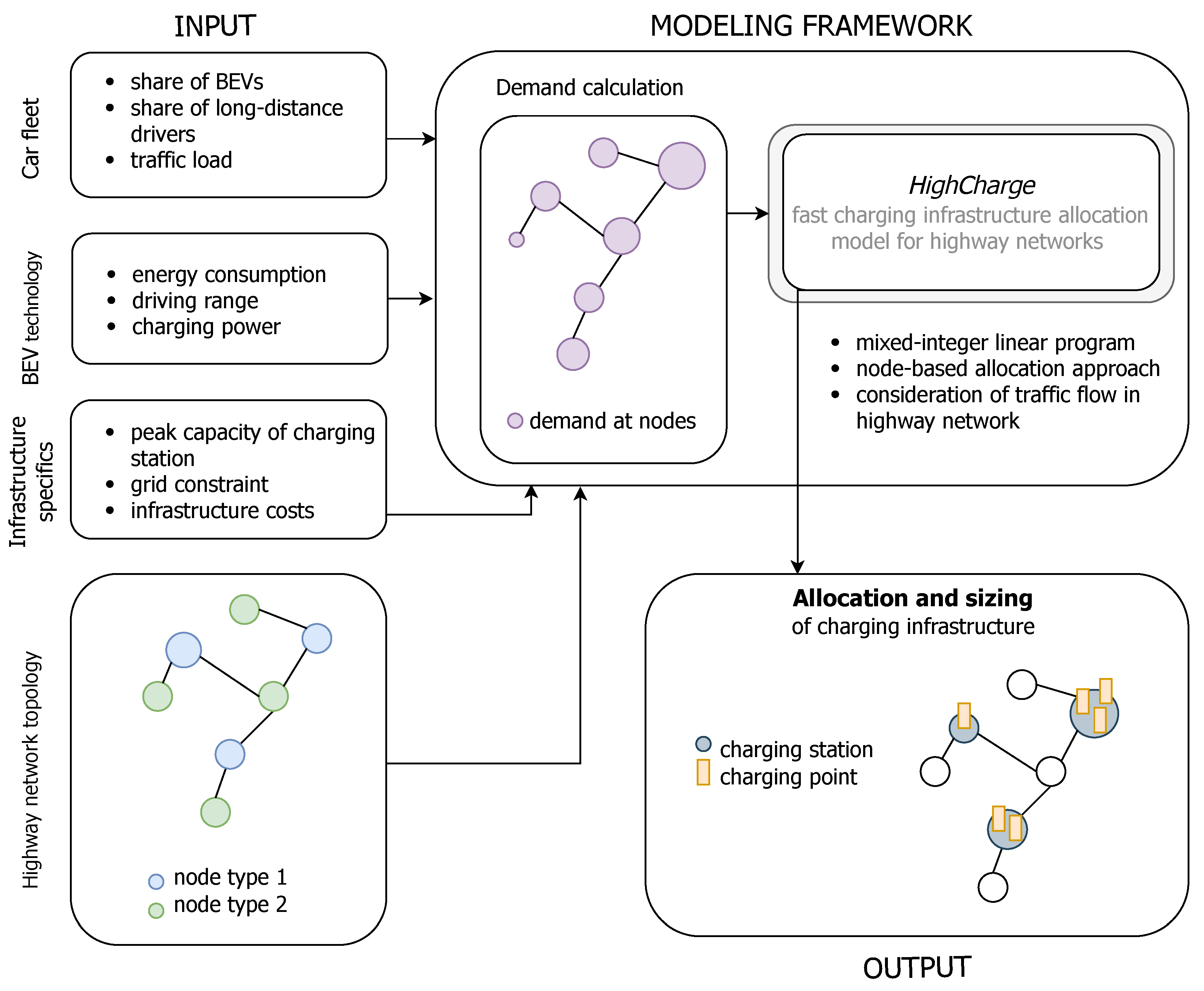
  • The formulation of the proposed allocation model follows the node-based approach, which we extend to the application for highway networks. This was decided to benefit from the simplicity of the input data of this approach. The nodes represent potential positions for charging infrastructure, i.e., service areas. Given a typically high density of service areas, this model feature allows the introduction of the charging demand in high spatial granularity and based on the local traffic load and distance between service areas. Unlike in the original formulation of a node-based allocation approach, the demand assigned to a node is not evaluated based on the population density but on the energy demand stemming from the accumulated energy consumed by the driving BEV fleet along the highway section between two nodes. The demand of a node is shifted and can be covered by charging stations at other nodes. Within this shifting, traffic flow movement is simulated, by which we also aim to introduce the benefits offered by flow-based approaches.
  • Comprehensive sensitivity analyses on the future share of BEVs, road traffic load, BEV driving range and charging capacity are conducted. It is foreseeable that the share of BEVs will increase, BEV technology will improve and the potential changes in mode split will affect road traffic load. Therefore, it is important to understand how these simultaneously occurring developments impact the requirements for fast-charging infrastructure.

3. Materials and Methods

3.1. Modeling Framework

The underlying methodology of this work is presented in Figure 1 and the used nomenclature in the following description of methodology is explained in Table 1. The approach in this proposed methodology follows a node-based approach which has been reported to be mostly used in the allocation of charging infrastructure in urban areas where the demand at a node is defined through population density [50]. In this work, this model formulation is extended to the application of high-level road networks by reformulating the definition of demand at a node based on the energy consumed through BEVs driving along the road network, rather than population density, and further, regarding traffic flow movement effecting the position of coverage of the demand.
In the following, the road connections between two junctions and between a junction and a network endpoint are referred to as segments, and the vertices are referred to as nodes. There are two types of nodes: some represent possible sites for charging station installation and lie along segments (node type 1), and others represent highway junctions or ending points of the network (node type 2). The nodes of type 1 can either be accessible from both driving directions ( k { 0 , 1 } ) or from only one direction ( k = 0 k = 1 ). At each node, a charging demand exists which can be covered at the node itself or at other nodes within a defined range, d i s t m a x . First, we proceed with a detailed description of the main contribution of this work, which is the mixed-integer linear program formulation of a node-based highway allocation method. Based on the demand at the nodes, the program allocates sites to install charging stations and sizes them by determining the optimal number of charging points. Then, the demand calculation used in this work is outlined.
Before continuing with the mathematical formulation of the proposed modeling framework, we elaborate on the key assumptions underlying the methodology:
  • The costs of a charging station include, on the one hand, onsite preparations to enable the support of large capacities given by the charging points locally ( c X ) and, on the other hand, hardware and construction costs associated with the installation of one singular charging point ( c Y ).
  • Service areas along highways are potential sites for charging stations. Areas that only offer parking places are not considered as potential sites due to limited space and infrastructure on site.
  • The BEV fleet traveling along the highway network is treated as a homogeneous quantity, allowing to consider accumulated charging demand and translating this into the optimal sizing of a charging station. Based on this assumption, the technical parameters of an average BEV are assumed, such as average driving range ( d i s t ¯ r a n g e , B E V ), energy consumption ( d ¯ s p e c , B E V ) and charging capacity ( P ¯ c h a r g e , B E V ).
  • All charging demands, n , k D ^ n k , result from the energy consumption of BEVs driving along the highway and need to be compensated for in total by charging stations built along the highway network.
  • Highway charging infrastructure is primarily used by long-distance drivers as BEV owners mostly charge at home or at work.
  • A fast-charging infrastructure along a highway network is designed based on peak demands, including seasonal peak demand ( f ^ l k ) and hourly peak demand during a day ( γ h ).

3.1.1. Optimization Model

The objective function of the optimization model is to minimize the total charging infrastructure investment costs:
min X l , Y l k , E ^ l k c h a r g e d , n k , D ^ l k i n , n k , D ^ l k o u t , n k c X l X l + c Y l k Y l k
The charging infrastructure is designed in such a way that all demand n , k D ^ n k in the network is covered. For each node the following energy balance is defined:
E ^ l k c h a r g e d , n k D ^ l k d e m a n d , n k = D ^ l k o u t , n k D ^ l k i n , n k : n k , l k A n k
Set A n k encompasses all nodes l k which are within the distance of d i s t m a x to node n k . d i s t m a x is obtained via d i s t m a x = 4 / 5 0.6 d ¯ r a n g e , B E V : The factor 4 / 5 accounts for reduced driving range resulting from increased energy demand at highway speeds [57,61] and 0.6 for charging processes starting at a state of charge of 20% up to 80% [37]. Within this set radius around a node n k , the energy demand stemming from node n k , D ^ n k has to be covered. Between the nodes l k , which are part of A n k , the demand is shifted, and for this the following holds for adjacent nodes l k and l k :
D ^ l k o u t , n k r l k , l k = D ^ l k i n , n k : n k , { l k , l k } A n k
For parameter r l k , l k , the following applies:
r l k , l k = 1 , if s l k = = s l k < 1 , otherwise
l k r l k , l k = 1
This rationing parameter is, therefore, only lower than 1, if node l is a junction point and in this case, the D ^ l k o u t p u t , n k needs to be split to simulate traffic flow partitioning at a junction point. For example, if three segments meet and it is assumed that traffic flow is split equally between these segments at the junction, then r = 1 / 2 .
The demand coverage by a charging point and charging station is defined through:
n k E ^ l k c h a r g e d , n k k Y l k P ¯ c h a r g e , B E V : l k
P m a x P ^ C P X l k Y l k : l
Equation (7) establishes the relation between the sizing of a charging station, i.e., the number of charging points, and the binary variable indicating whether a charging station is installed at node l.

3.1.2. Charging Demand Calculation

To each node n in the network, a charging demand is assigned for each direction k from which it is accessible. For this, daily traffic counts are utilized to estimate the number of cars passing at all node positions n and driving in direction k. To take into account the demand of maximum traffic load to the charging infrastructure in the analysis, the maximum daily traffic count values are obtained from the measurements performed for a span of 1 year. Then, the following is performed for each segment s in the direction k of the highway network: all traffic counter positions lying on s are mapped onto the segment, and a function expressing traffic load in dependence of the distance in the traveling direction is approximated using the general regression neural network (GRNN) model, which is able to estimate various forms of underlying functions using Gaussian functions given few input data points [62]. Using the function G R N N s k ( d i s t ) , the peak daily traffic loads are approximated for all nodes n, which lie on segment s and are accessible from the driving direction k:
f ^ n k = G R N N s k ( d i s t n s k )
To obtain the charging demand at node n k resulting from the energy consumed along the distance driven since passing the last node n 1 k , the integral between these distances is calculated and multiplied by the specific energy demand d ¯ s p e c , B E V by one BEV:
D ^ n s k = d ¯ s p e c , B E V ϵ μ γ h α d i s t n 1 d i s t n G R N N s k ( d i s t ) , d d i s t
ϵ describes the share of BEVs in the car fleet, whereas μ expresses the share of long-distance drivers. Factor γ h expresses the share of daily travels appearing during the peak hour of a day. Parameter α is introduced as a factor that allows to express relative changes in the overall traffic load along highways between the year during which the traffic counts were obtained and the year for which the demand is modeled; this allows to take into account the decrease in road traffic due to activity reduction or modal shift. Rationing parameter r (in Formulas (4) and (5)) is defined for each junction based on the values approximated for the given node by the function G R N N s k ( d i s t ) of all segments the junction node is part of.

3.2. Case Study, Scenarios and Input Data

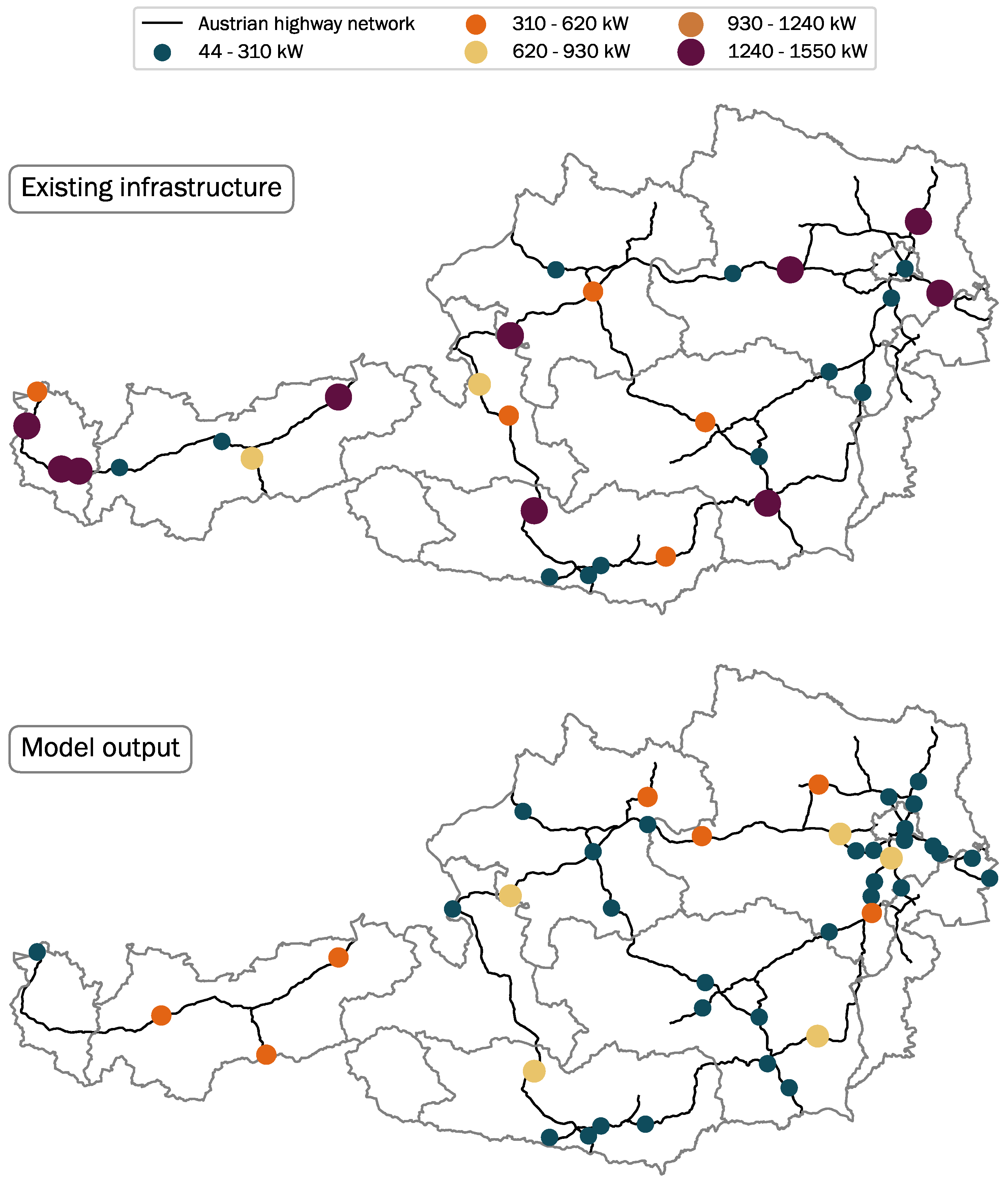
3.2.1. Austrian Case Study

The proposed modeling framework is applied to Austria’s highway network by modeling a cost-optimal charging infrastructure expansion for 2030 under different future scenarios. In this study, year 2030 has been chosen mainly due to the two following reasons: the first is that the aim of the analysis of this paper is to illustrate short-term infrastructure requirements (short term in terms of infrastructure planning), and the second is that it is a significant year in decarbonization plans for the transport sector, as the Paris Agreement explicitly states a 20% electrification of global road transport by 2030 [6].
To extrapolate future scenarios model input parameters were set, which describe the current status of Austria in 2021. Table 2 presents the selected values. Until the end of December 2021, 76,539 electric vehicles have been registered in Austria [7], which make up for 1.5% of all the registered passenger cars in Austria. In order to determine traffic load on highways during peak hour and the share of long-distance drivers, the most recently acquired data (Austrian wide) on mobility patterns were used [63]. Similar to the work of Jochem et al. [64], it was assumed that all car trips taking longer than 45 min and longer than 25 km or car trips longer than 50 km are the most probable to include driving on highways or motorways. Furthermore, trips were classified as long distance if the drive was at least 100 km long, following the common definition of long-distance travel [65]. Based on the starting times of these trips, it was evaluated that during the hour of peak demand on Austrian highways 12 % of the daily traffic takes place, and 24% of the traffic is long-distance travelers.
Traffic counts were obtained from ASFINAG [66], which provide averaged weekly traffic counts for up to 276 positions along Austrian highways and motorways. Their data encompasses counts for vehicles of two categories, namely: vehicles weighing up to 3.5 tons and those weighing greater than 3.5 tons. As no differentiation is made between light-duty vehicles and passenger cars in the category of <3.5 tons, it was assumed that all vehicles of this category are passenger cars, as light-duty transport will also be transitioned to electromobility [8]. Data for the year 2019 was chosen to be representative for 2021 as the complete data set for 2021 has not been published as of the time of the conduction of this analysis, and the 2020 dataset cannot be used due to being effected by the month-long lockdowns during the COVID-19 pandemic.
The technical parameters d ¯ s p e c , B E V , d i s t ¯ r a n g e , B E V and P ¯ c h a r g e , B E V were set in such a way that they would represent an average Austrian BEV. For this, the technological attributes of the respective top 10 sold cars during the years 2019, 2020 and 2021 were used to evaluate the average values (see Appendix A for details on this).
The infrastructure cost component c X is particularly difficult to set here as these onsite preparation costs may significantly vary based on the location of the site. Indications for the approximation of this value were drawn from [45,64,67]. The installation costs of one charging point, c Y , was assumed to be EUR 60,000 for the hardware of a charging pole with P ^ C P = 150 kW—which currently enables the fastest charging of passenger cars—an added construction costs of EUR 7000 [67,68]. Furthermore, it was assumed that the maximum installed capacity at a charging station is 12 MW.
The shape of the Austrian highway and motorway network was mapped based on geographic data by OpenStreetMap contributors [69]. The positions of the service areas were gathered based on the information drawn from ASFINAG [70] and complemented with geographic information from OpenStreetMap contributors [69]. The retrieved highway network used throughout the analysis has an overall length of 220 km and consists of 55 segments. Moreover, there are 249 nodes in total, 139 of which represent service areas and 110 junctions. Further details on data preparation are found in the Appendix A.3.

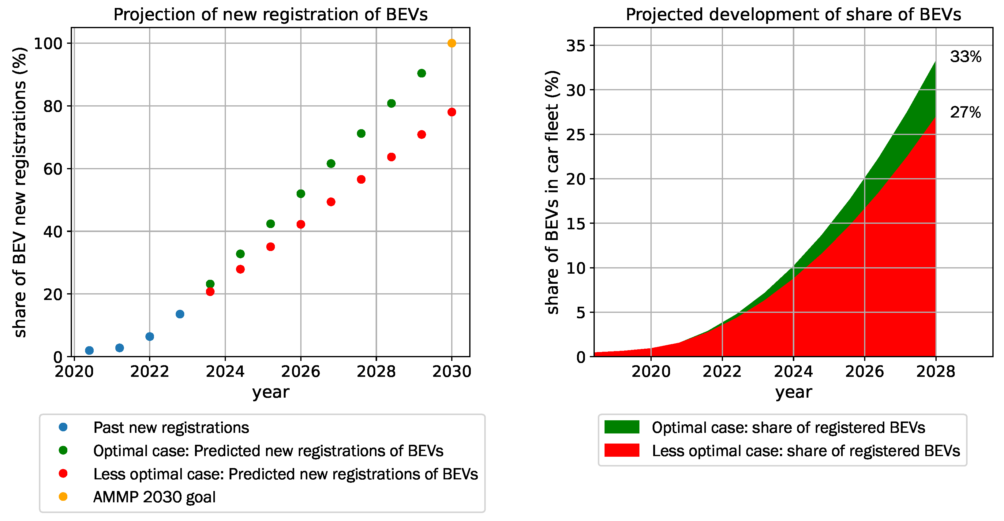
3.2.2. Future Scenarios

Four quantitative scenarios for Austrian highway charging infrastructure expansion are outlined. These were developed in the course of the Horizon 2020 research project openEntrance [71]. The scenarios outline pathways to climate change mitigation by reaching the 1.5 °C or 2.0 °C targets and are referred to as the Societal Commitment (SC), Techno Friendly (TF), Directed Transition (DT) and Gradual Development (GD) scenarios. The former three pathways aim to mitigate climate change by keeping the temperature rise to a maximum of 1.5 °C as specified in the Paris Agreement, the latter to 2.0 °C. Within these scenarios, the extent of societal engagement, implementations of technological novelties and the strong presence of political interventions in climate change mitigation vary see also [72,73]. These scenarios were developed to outline mitigation paths for different economic sectors in Europe and are used here to align the analysis described in this paper into the large-scale context of decarbonization. Based on this, different developments of the transport sector relevant to the present work are projected:
  • Societal Commitment (SC): Within this scenario, politics are strongly intervening, which is met by wide-spread societal acceptance, triggering behavioral changes in the face of awareness of the necessity of climate change mitigation; while this scenario is characterized by a reduction in energy demand due to behavioral changes, societal engagement supporting circular economy and new market solutions, it is assumed that no significant technological breakthroughs appear. This translates in the transport sector to an increased modal shift to sharing concepts and public transport, which causes a significant decrease in individual passenger road transport.
  • Techno Friendly (TF): This setting combines the appearance of major technological breakthroughs and strong societal engagement, which results in an increased top-down push effect in the application of new technologies that improve energy efficiency. Simultaneously, similarly as in the SC scenario, there is a strong social commitment driving an increased modal shift away from individual passenger car transport.
  • Directed Transition (DT): Similarly as in the TF scenario, there is a strong active policy push supporting new technology options, while there are major technological developments, the social commitment to adopting such developments is missing. This results in the moderate growth of BEV share throughout the years and a decreased modal shift, but registered BEVs of the Austrian car fleet still show similar technological improvements as in the TF scenario.
  • Gradual Development (GD): This scenario represents the projection of less ambitious climate change mitigation goals. It embodies the exertion of all three dimensions, namely, social engagement, technological breakthroughs and significant political interventions, only a weaker extent of each. Therefore, while BEV penetration will grow to some degree and technological improvements will appear, no changes in mobility patterns are expected for this pathway.
Based on these scenario descriptions, we embed projections on changes in the modal split and developments in the BEV technology in European climate mitigation pathways for 2030. Parameters ϵ and α are specified based on the climate change mitigation goals for Austria’s passenger transport sector described in the governmental document “Austria’s Mobility Master Plan 2030” (AMMP) [8]. One of these key goals is to reduce motorized private transport by 31 % between the years 2018 and 2040 to meet the 1.5 °C target set by the Paris Agreement. In the SC scenario, where strong societal and political engagement act together, this goal will be met by 2030. The AMMP further specifies that by 2030, 100 % of newly registered passenger vehicles must be exclusively powered by an electric engine. In the SC and TF scenarios, it is assumed that the share of new registrations of electric vehicles will gradually increase until 100% in 2030 due to the strong awareness of the necessity of electromobility by society. For the DT and GD scenarios, the steady growth rate as experienced in 2020–2021 is projected until 2030, which will result in an EV share of 27 % . (This was calculated under the assumption that the size of the Austrian car fleet will not grow further from today.) Table 3 presents the projected values. The presence of major technological breakthroughs is expressed by a significant development in the driving range of BEVs and increasing charging power, which is in line with the current major focus in BEV technology research on battery technology with the goal of allowing faster charging and longer trips [11,74]. According to the study by Thielmann et al. [74], there is a great potential in battery storage research suggesting that technological breakthroughs in the next years could lead to the sale of BEVs with a driving range of up to 1000 km. Based on this, the sale of BEVs with an average driving range of up to 800 km is projected for 2030 in the TF and DT scenarios, whereas in the SC scenario, this range is assumed to be 450 km, being slightly larger than the ranges of BEVs currently on the market (see Table A1 in Appendix A). To reflect a weak extent of technical developments in the GD scenario, the increase in the average driving range of up to 600 km is projected for 2030.
To compare the results of the scenarios, a similar peak power for charging points is assumed for all four scenarios. The study by IRENA [11] projected P ^ C P = 350 kW to be the predominant peak charging power by 2030. The costs for the hardware of a charging pole are estimated to be EUR 120,000, as well as an additional construction cost of EUR 7000 [75,76]. To reflect different improvements in charging efficiency, technological breakthroughs are assumed to lead to charging power levels of up to P ¯ c h a r g e , B E V = 315 kW given that efficiency will increase up to 90%, as nowadays charging poles have a peak capacity of 50 kW [77]. Today, one of the passenger car models with the highest charging power is the Porsche Taycan, with P ¯ c h a r g e , B E V = 197 kW. For the SC and GD scenarios, this is assumed to be adopted by all BEV vehicles by 2030.
Other model input parameters are assumed to be similar as in 2021, using the values from Table 2. Table 4 summarizes the overall projected values describing the average Austrian car fleet in 2030, which were extrapolated based on the assumption that these parameters would gradually change in a linear way until 2030 on the basis of the values for 2021 (see also Appendix A.2).

3.3. Model Validation and Limitations

The model is validated by modeling present-day infrastructure requirements and comparing the results with the setup of the existing infrastructure. The current infrastructure requirements are modeled using input parameters displayed in Table 2. In Figure 2, the capacities of the currently installed fast-charging infrastructure along Austria’s highways (as of December 2021) are illustrated along with a comparison with the model output. Table 5 presents the numbers of fast-charging points of different peak power levels and total capacity.
While the overall amount of charging stations seems to be in a similar range, a gap appears to exist between the total installed capacity estimated by the model versus the existing capacity. There are several possible reasons for this. One might be that the proposed modeling framework aims to design a minimum required charging infrastructure for a given point in time, therefore, no pre-planned charging capacities with regard to developments in the future is modeled. In existing infrastructure this is not the case, as for example IONITY [78], the joined venture by multiple cars producers, has installed most of the charging points with P ^ C P = 350 kW while currently only few cars on the market are able to charge at a power level above 150 kW [68]. Therefore, in this context, the modeled infrastructure reflects the minimum requirements for a fast-charging infrastructure. Moreover, the difference could stem from the fact that the model assumes charging points of a singular peak power level and all BEVs of the Austrian car fleet having the same technical parameters, which makes it difficult to directly compare existing and modeled capacity because the charging points of different peak power levels have different efficiencies and the average charging capacity varies significantly among car models see, e.g., [68].
The difference in the location distribution of capacities can be attributed to the model assumption that the proportion of long-distance travelers among highway traffic is equal throughout the whole highway network. Furthermore, local differences of the cost parameter c X are neglected, whereas in reality, this cost component significantly varies depending on location [45]. Another reason for the difference in site allocation can be that within the model all energy is aimed to be covered and, given the geographical boundary of Austria, charging stations lying right outside the country’s boarders are not considered. Therefore, the model tends to install charging stations at service areas that are closest to the end points of the highway network to cover all demands within the network. Another striking difference between existing and modeled fast-charging infrastructure is the accumulation of many small charging stations in the vicinity of Vienna—which lies in the east of Austria—in the modeled infrastructure. Some of them may stem from the tendency of installing charging infrastructure near borders, whereas others are most likely installed there due to the dense topology of the highway network around Vienna. Jochem et al. [49], who modeled fast-charging infrastructure along the European highway network, also observed that within networks of higher densities more and smaller charging stations are placed by the allocation model.

3.4. Open-Source Programming Environment and Data Availability

The described modeling framework was implemented using Python 3.8 and the Python package pyomo 6.2 [79]. All materials for the analysis in this paper are publicly available on GitHub (https://github.com/antoniagolab/HighCharge, accessed on 20 February 2022). In the application of the mixed-integer linear program in the Austrian case study, the number of nodes is 249. The number of constraints is about 1.3 and varies slightly depending on the input parameter expressing the average driving range of BEVs, d i s t ¯ r a n g e , B E V . The time of a model run heavily depends on the specified BEV driving range: For example, at 400 km the total model run takes 650 s and at 800 km 1360 s, yielding a solution of up to an optimality gap of 0.2%.

4. Results

In this section, the most relevant results are presented. It is divided into two parts: First, we elaborate on the expansion requirements for the existing fast-charging infrastructure along Austria’s highway network under different future scenarios for 2030. Details on the results obtained for the DT scenario, for which the costs of fast-charging infrastructure expansion are the lowest, are presented. Subsequently, the results of the modeled expansion given four different scenarios, SC, TF, DT and GD, are compared based on parameters describing the costs and the required charging infrastructure expansion. To gain better insight into how the observed differences between the scenarios come to place, selected input parameters of the scenario result with the highest infrastructure expansion costs for 2030, which is the GD scenario, are altered. In the second part of this section, the focus shifts from the required infrastructure expansion for 2030 to the analysis of changing infrastructure requirements in the face of technological development and increasing demand. First, the effect of change in the driving range of an average BEV is observed and second that of increasing demand by the rising share of BEVs in the Austrian car fleet.

4.1. Expansion of Fast-Charging Infrastructure along Austrian Highway Network under Different Scenarios for 2030

Under the consideration of existing charging points with the peak capacity of P ^ C P = 350 kW, which is assumed to be the predominant charging capacity of fast-charging infrastructure for 2030, and the assumption that the investment of on-site preparation ( c X ) has been made for all existing charging stations with charging points allowing fast-charging, the expansion of the current charging infrastructure along the Austrian highway network was modeled under different climate mitigation scenarios.

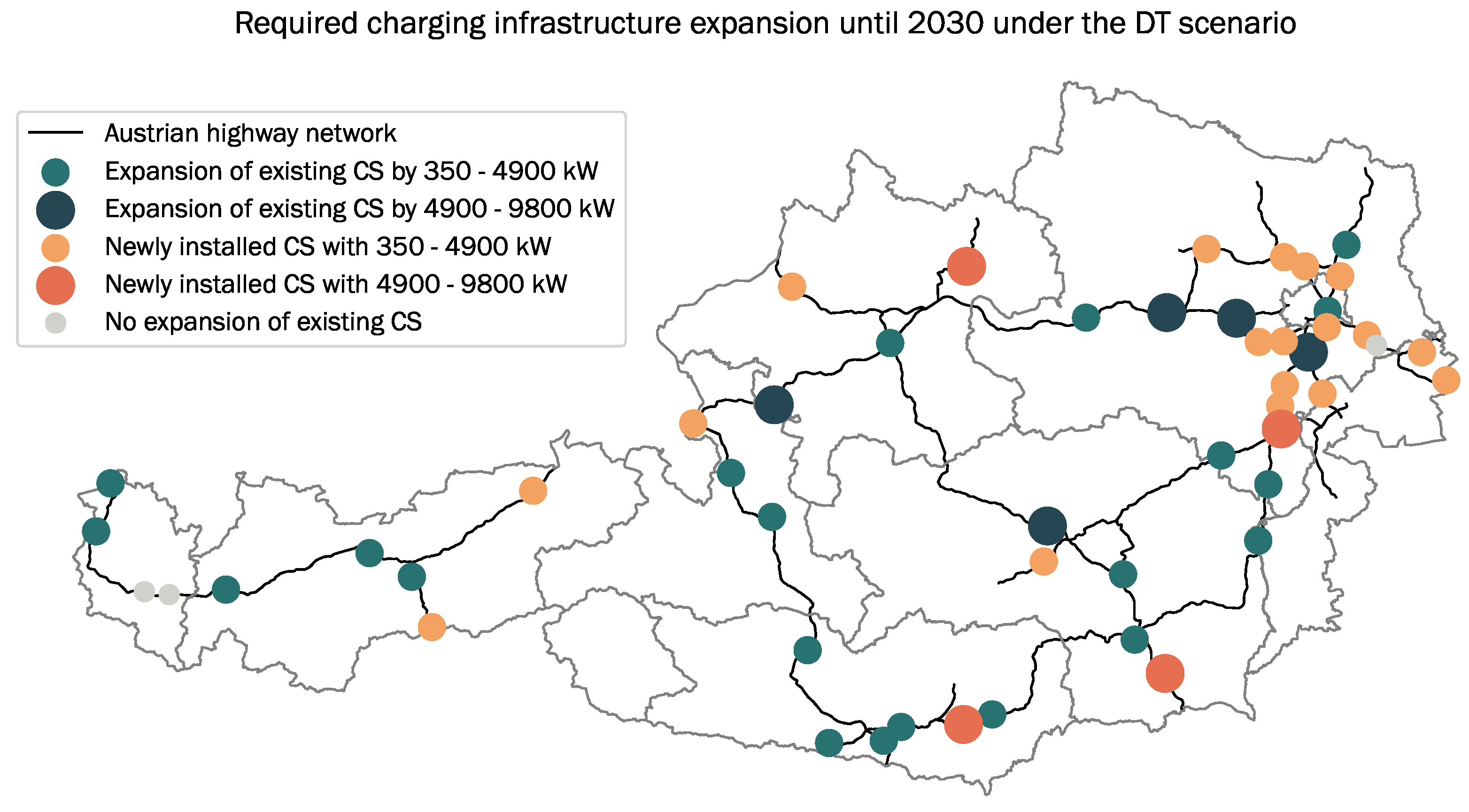
4.1.1. Austria’s Fast-Charging Infrastructure for 2030 under the Directed Transition Scenario

Table 6 and Figure 3 display the modeling results for the expansion of the current 350 kW charging infrastructure along highways in Austria for 2030 under the DT scenario. In Figure 3, the charging infrastructure expansion is expressed through additionally needed capacities. The expansions at existing charging points are indicated in dark green and required capacities at newly installed charging points are indicated in orange. The charging stations in the lighter shades of green and orange indicate the required expansion of 350–4900 kW, i.e., by 1–14 charging points, and charging stations in the darker shades installations of additional 5200–10,500 kW, i.e., 15–28 additional charging points. The total infrastructure expansion costs are estimated to be EUR 54 M, which are translated to EUR/kW 369 and EUR 39 per registered BEV in the Austrian car fleet in 2030, while currently 40 charging points with P ^ C P = 350 kW, i.e., 14 MW, are installed along Austrian highways, an additional +146 MW of charging capacity are required until 2030. Further, an additional 24 charging stations are needed, of which 10 are positioned within the dense part of the highway network in the east of Austria in the vicinity of Vienna. The results also indicate the need for the installation of new charging stations near the Austrian border in order to cover all demand within the boarders, which mostly results from the model formulation enforcing all coverage of demand within the network as described in Section 3.3. Aside from this, there exist three charging stations that do not need any infrastructure expansion.

4.1.2. Comparison of the Results from Different Future Scenarios

Table 7 presents a comparison of key parameters describing the required infrastructure expansion under different future scenarios for Austria in 2030. The following observations are made:
  • The expansion under the DT scenario, for which the input parameters were set based on the assumption of a strong presence of political incentives pushing technological developments, results in the lowest costs of charging infrastructure expansion (EUR 54 M).
  • There is a relative difference of up to + 84 % between the scenario causing the minimum expansion costs (DT) and the highest costs arising in the GD scenario, within which weaker climate change mitigation measures are assumed.
  • The number of charging stations remains in a similar range for all scenarios, varying between 54 and 57. The specific infrastructure expansion costs per kW remain also very stable at around 368 EUR/kW.
  • The specific costs per BEV range between 39 and 72 and are the lowest in the TF and DT scenarios. The common trait of these two scenarios is the presence of technological breakthroughs leading to higher driving ranges and charging capacity of BEVs.

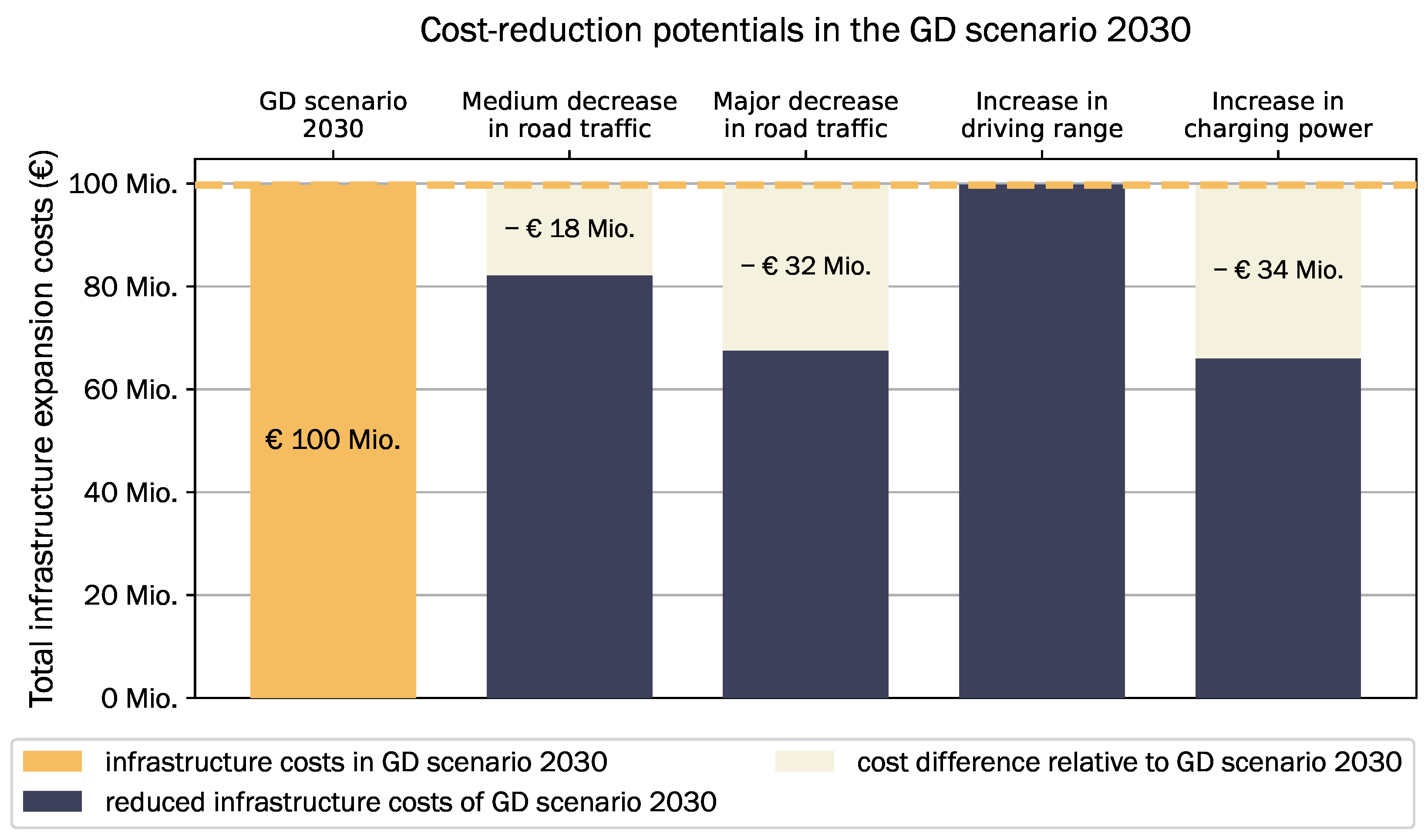
4.1.3. Cost-Reduction Potentials in the Gradual Development Scenario

To shed light onto why the infrastructure expansion costs in the GD scenario are up to + 85 % higher than in the other scenarios and how the high specific costs per BEV of 72 EUR/BEV come to place, selected input parameters are altered and the effects on the costs are observed. These alterations reflect developments which are absent in the GD scenario but present in the others, which essentially lead to a cost reduction in charging infrastructure expansion investments. The following projections are drawn from the other scenarios, and based on these input parameters are altered in the GD scenario: a medium decrease in road traffic of 17 % by 2030 as in the TF and DT scenarios, a major decrease of 31 % as in the SC scenario; technological breakthroughs as in the TF and DT scenarios altering the driving range of an average BEV sold in 2030 to be 800 km and the average charging power of 315 kW at a charging point with P ¯ C P = 350 kW. There are further details on these alterations displayed in Table 8.
Figure 4 and Table 9 display the resulting cost reductions and changes in the required fast-charging infrastructure in response to the respective parameter changes. The lowest infrastructure expansion costs are achieved through the increase in BEV charging power, which causes a large decrease in the required capacity as the efficiency of charging increases. Similarly, high cost reduction is accomplished by decreasing the overall traffic load, which essentially reduces the demand for charging infrastructure. No cost reduction results from the increase in BEV driving range. Figure 4 illustrates these changes in costs in response to the specific parameter alterations visually.

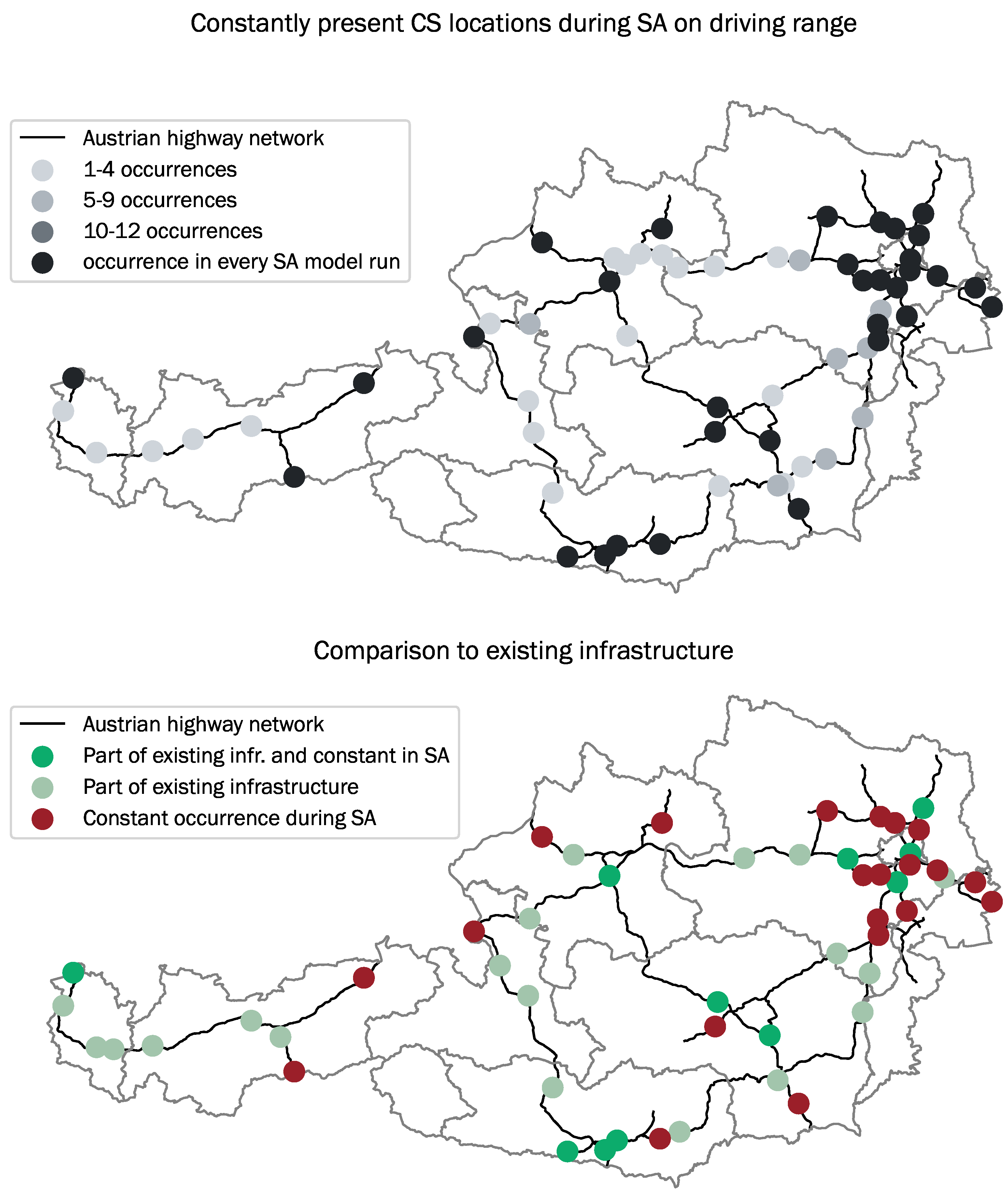
4.2. Sensitivity Analyses on the Requirements for Fast-Charging Infrastructure

In the following, the mere infrastructure requirements in 2030 without regards to the charging infrastructure currently in place are analyzed. This is conducted to better understand how requirements for the fast-charging infrastructure change as a function of technological BEV parameters and in response to growing demand. First, the effect of the average driving range of an average BEV in the Austrian car fleet is observed in the context of the TF scenario during which major developments in battery technology are expected. Second, the change in modeled charging infrastructure depending on the BEV share in the car fleet within the SC scenario, which reflects high societal commitment to BEV uptake, is demonstrated.

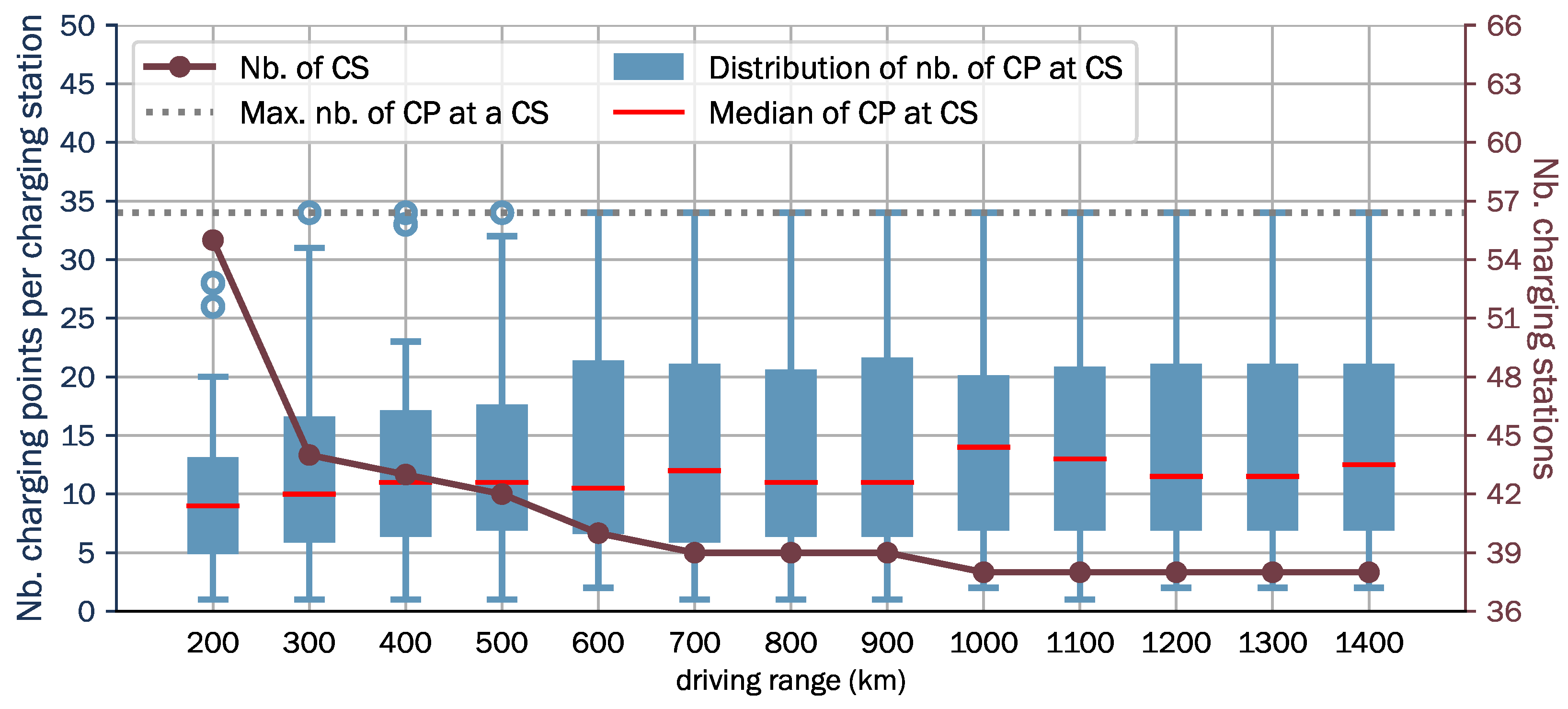
4.2.1. Increasing Driving Range in the Techno-Friendly Scenario

The driving range is altered between 200 and 1400 km. Figure 5 presents the changing distribution of the number of charging points at the charging stations and total number of charging stations in response to gradually increasing driving ranges in the TF scenario. In this figure, the blue boxplots display the distribution of charging points (CP) along the charging stations (CS). The gray dashed line indicates the maximum possible number of charging points at a charging station, which is 34. This is given by the maximum installed capacity of 12 MW at a charging station. The dark red connected points indicate the total number of charging stations in the modeled charging infrastructure. Table 10 presents the change in the key parameters for the driving ranges of 200, 800 and 1400 km and gives an impression of how the key parameters of the modeled fast-charging infrastructure change in the course of the conducted sensitivity analysis. Given the assumed development in the TF scenario, the average driving range of BEVs in the Austrian car fleet is projected to be 670 km by 2030 and reach approximately 1000 km by around 2040.
With the increasing range, energy demand can be shifted further away from the node where it originates, which results in wider solution space during the optimization. Overall, the infrastructure costs stay stable between EUR 71 M and EUR 72 M throughout this parameter alteration. The total number of charging stations decreases from 55 at 200 km to a minimum of 38 at 1100 km. The installed capacity stays constant. Starting at the range of 300 km, fully occupied charging stations occur throughout the sensitivity analysis. Overall, the highest costs of investments are at 200 km and drop to EUR 71 M at the range of 500 km.
During this analysis, the model was run for each of the ranges between 200 and 1400 km every 100 km and, therefore, a total for 13 times. During all of these model runs, at 34 of all the service areas, charging station installations occurred in each of the model runs. The top sub-figure in Figure 6 illustrates these charging stations in black. The bottom illustration shows which of these are currently existing charging stations (in bright green) and which are not (in red). Overall, 11 of these 34 permanent charging stations are existing charging stations.

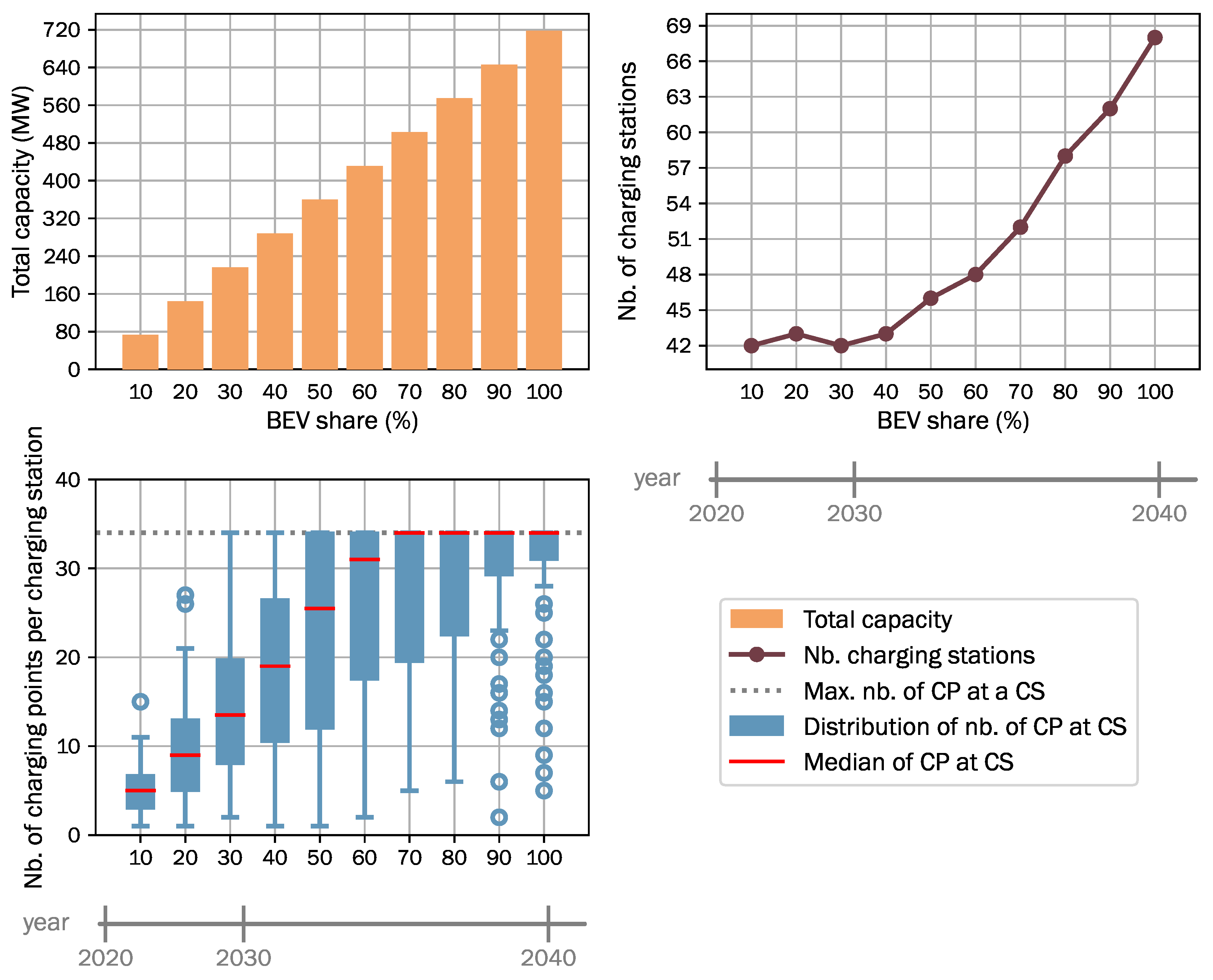
4.2.2. Increasing Share of BEVs in the Societal Commitment Scenario

Figure 7 presents the results of the sensitivity analysis on the share of BEVs in the Austrian car fleet under the SC scenario for 2030. The top-left sub-figure presents the total installed capacity of the fast-charging infrastructure as a function of the rising share of BEVs. The top-right sub-figure displays the change in the number of charging stations. Boxplots illustrating the distribution of the number of charging points at charging stations are presented in the bottom-left sub-figure. The timeline in this figure is projected based on the assumption that as of 2030 all registered cars will be BEVs and a BEV has a lifetime of 10 years, which would lead to an Austrian car fleet that is 100% electric by 2040. Table 10 presents the values of parameters describing the key features of modeled infrastructure for the different shares of BEVs, 10%, 50% and 100%.
The required capacity for fast-charging is rising linearly with the share of BEVs. The number of charging stations is significantly increasing between 40% and 100%, indicating the requirement for a densification of the fast-charging infrastructure. This effect of densification can be attributed to the increasing amount of fully occupied charging stations which is visible in the bottom-left sub-figure of Figure 7. The overall cost increases by a factor of about 10 between 10% and 100% share of BEVs, and so does the required capacity.

5. Conclusions

The decarbonization of the passenger sector is an important topic and the diffusion of battery electric vehicles (BEVs) is one of the main solutions to counteract the increase in greenhouse gas emissions in the face of globally growing transport demand. A sufficient and demand-oriented fast-charging infrastructure is needed to support the diffusion of BEVs. The proposed modeling framework reflects the cost-optimal expansion of the fast-charging infrastructure along highways in terms of enabling long-distance travel with BEVs. We present one of the first studies incorporating the effects of changes in modal split as well as technological developments of BEVs in the design of a fast-charging infrastructure for the future. In our analysis, we observed the effects of charging capacity, BEV share and the reductions of road traffic load.
Particularly, the average charging power level of a BEV is found to have a significant impact on the costs of charging infrastructure installation. With higher charging power of the BEVs, the required infrastructure expansion at growing BEV share can be reduced. As there is a need to invest in technological developments to overcome the barriers of BEV adoption, we found that these investments can also induce cost savings in infrastructure expansion.
In future work, this proposed modeling approach will be compared with flow-based approaches in terms of computation performance and model output. Based on this comparison, the benefits of both approaches could be exploited within the model formulation. Moreover, a verification of the proposed top-down modeling approach could be conducted by testing whether the modeled charging infrastructure is sufficient to meet the fast-charging demand by a traffic flow simulation by means of introducing origin and destination nodes and observing whether the charging demand by all long-distance trips is sufficiently covered and travel times are not substantially prolonged by, e.g., queuing at charging stations. Based on this, the model can be expanded by introducing temporal granularity with regard to charging processes and traffic flow. This can also help in the allocation of charging infrastructure, not only in response to yearly peak demand, but also in such a way that the profitability of hosting the charging stations is also ensured. Moreover, as it has been found in this paper that technological developments and changes in mobility behavior have significant impact on the required infrastructure but are also quite uncertain in the future, the goal for future work is to add uncertainty measures that would help in modeling a more realistic charging infrastructure expansion. Building on the insights gained into the impact of technological developments and increasing demand, an extension of the model by the means of the introduction of a temporal dimension in yearly resolution can help model charging infrastructure requirements as a function of changes in technology, modal split and BEV fleet size in time. This could assist policy makers in making cost-optimal investment decisions throughout the years.

Author Contributions

Conceptualization, A.G., S.Z.-B. and H.A.; methodology, A.G., S.Z.-B. and H.A.; software, A.G.; validation, A.G.; formal analysis, A.G.; investigation, A.G.; resources, A.G.; data curation, A.G.; writing—original draft preparation, A.G.; writing—review and editing, A.G., S.Z.-B. and H.A.; visualization, A.G.; supervision, H.A.; project administration, H.A.; funding acquisition, H.A. All authors have read and agreed to the published version of the manuscript.

Funding

Open Access Funding by TU Wien Bibliothek.

Institutional Review Board Statement

Not applicable.

Informed Consent Statement

Not applicable.

Data Availability Statement

Data sharing not applicable.

Acknowledgments

The authors acknowledge TU Wien Bibliothek for financial support through its Open Access Funding Program.

Conflicts of Interest

The authors declare no conflict of interest.

Appendix A. Supplementary Details on Methodology and Materials

Appendix A.1. Determination of Average Technological Parameters for BEVs

To evaluate the technological parameters of an average battery electric vehicle (BEV) in the Austrian car fleet, the technological attributes of the most sold car models from the last 3 years were used. These are displayed in Table A1 with the respective number of sales. Using sale numbers as weights, the weighted averages for the driving range and charging capacity were evaluated.
Table A1. Top 10 sold car models in Austria in 2019–2021 and technical attributes [80,81,82] (average driving range d i s t ¯ r a n g e , B E V , average charging power P ¯ c h a r g e , B E V , average specific energy demand d ¯ s p e c , B E V ).
Car ModelSales 2019Sales 2020Sales 2021 dist ¯ range , BEV (km) P ¯ charge , BEV
at P ^ CP = 150  kW
(kW)
d ¯ spec , BEV
Highway-Cold Weather
(kWh/km)
Tesla Model 32342289233043801100.23
Renault Zoe94420711778310410.22
Kia Niro1125421924370770.24
Hyundai Kona897861-395640.28
Audi e-Tron36478211922851140.29
BMW i31191697-235470.23
VW e-Golf805401-190390.24
VW Up!-376-205300.22
Mazda MX-30-370-170340.25
Peugeot 208-355-285780.23
Hyundai Ioniq361--250360.22
Nissan Leaf557--225400.23
Tesla Model S389--5601100.23
VW ID.3--2361350850.23
VW ID.4--23614001030.27
Skoda Enyaq--22084201030.26
Fiat 500--1356235670.23
Seat Mii--936205300.22
Tesla Model Y--9214351080.24
Weighted average values 340810.24

Appendix A.2. Details on the Projected Developments for 2030 under Different Scenarios

For the quantification of the scenarios used in the analysis, projections on the development of BEV share had to be made. For the Societal Commitment and Techno-Friendly scenarios an optimistic projection was made based on the decarbonization goals for the transport sector in the governmental document “Austria’s Mobility Master Plan 2030” [8]. A pessimistic projection is made for the Directed Transition and Gradual Development scenarios based on the trend of new registrations of BEVs in the years between 2018 and 2020.
Figure A1. Projections of linearly increasing new registrations of BEVs (left, AMMP = Austria Mobility Master Plan [8]) and based on this, developments of share of BEV (right).
Energies 15 02147 g0a1

Appendix A.3. Details on Preparation for the Austrian Case Study

The underlying data pre-processing procedures of this work encompassed the preparation of the graph representation of the Austrian high-level road network and the potential sites for the installment of charging stations. Geographic data representing the Austrian highways and motorways was obtained based on OpenStreetMap data [69]. For this, all way instances with tags highway = ‘motorway’ and highway = ‘trunk’ were retrieved and further processed using ArcGIS Pro [83] in order to obtain a clean shape representation of the road network, including the representation of both driving directions through parallel lines. Geographic data implying positions of service areas were retrieved using tags highway = ‘services’ and highway = ‘rest_area’. This geographic information was paired with data on service areas obtained through ASFINAG [70] which provide information on the driving direction a service area is accessible from and on the services offered on site.

References

  1. IEA. Global EV Outlook 2020. 2020. Available online: https://www.iea.org/reports/global-ev-outlook-2020 (accessed on 20 February 2022).
  2. Moriarty, P.; Honnery, D. Low-mobility: The future of transport. Futures 2008, 40, 865–872. [Google Scholar] [CrossRef]
  3. Malmgren, I. Quantifying the Societal Benefits of Electric Vehicles. World Electr. Veh. J. 2016, 8, 996–1007. [Google Scholar] [CrossRef] [Green Version]
  4. Spöttle, M.; Jörling, K.; Schimmel, M.; Staats, M.; Grizzel, L.; Jerram, L.; Drier, W.; Gartner, J. Research for TRAN Committee-Charging Infrastructure for Electric Road Vehicles; European Parliament: Strasbourg, France, 2018. [Google Scholar]
  5. Norwegen—Verteilung der Antriebsarten. Available online: https://de.statista.com/statistik/daten/studie/695029/umfrage/marktanteil-von-elektrofahrzeugen-in-norwegen/ (accessed on 10 February 2022).
  6. United Nations Framework Convention on Climate Change. Paris Declaration on Electro-Mobility and Climate Change and Call to Action; United Nations: New York, NY, USA, 2015. [Google Scholar]
  7. BEO. E-Mobilität in Zahlen. 2022. Available online: https://www.beoe.at/statistik/ (accessed on 27 January 2022).
  8. BMK. Mobilitätsmasterplan 2030 Neuausrichtung des Mobilitätssektors. 2018. Available online: https://www.bmk.gv.at/themen/mobilitaet/mobilitaetsmasterplan/mmp2030.html (accessed on 14 February 2022).
  9. Coffman, M.; Bernstein, P.; Wee, S. Electric vehicles revisited: A review of factors that affect adoption. Transp. Rev. 2017, 37, 79–93. [Google Scholar] [CrossRef]
  10. Biresselioglu, M.E.; Demirbag Kaplan, M.; Yilmaz, B.K. Electric mobility in Europe: A comprehensive review of motivators and barriers in decision making processes. Transp. Res. Part A Policy Pract. 2018, 109, 1–13. [Google Scholar] [CrossRef]
  11. IRENA. Innovation Outlook: Smart Charging for Electric Vehicles; International Renewable Energy Agency: Abu Dhabi, United Arab Emirates, 2019. [Google Scholar]
  12. Thielmann, D.A.; Neef, D.C.; Hettesheimer, D.T.; Döscher, D.H.; Wietschel, D.M.; Tübke, D.J. Energiespeicher-Roadmap (Update 2017): Hochenergie-Batterien 2030+ und Perspektiven Zukünftiger Batterietechnologien; Fraunhofer ISI: Karlsruhe, Germany, 2017; p. 120. [Google Scholar]
  13. Neaimeh, M.; Salisbury, S.D.; Hill, G.A.; Blythe, P.T.; Scoffield, D.R.; Francfort, J.E. Analysing the usage and evidencing the importance of fast chargers for the adoption of battery electric vehicles. Energy Policy 2017, 108, 474–486. [Google Scholar] [CrossRef]
  14. European Parliament. Deployment of Alternative Fuels Infrastructure: Fit for 55 Package. 2021. Available online: https://www.europarl.europa.eu/RegData/etudes/BRIE/2021/698795/EPRS_BRI(2021)698795_EN.pdf (accessed on 20 February 2022).
  15. Sims, R.; Schaeffer, R.; Cruz-Núñez, X.; D’Agosto, M.; Dimitriu, D.; Figueroa Meza, M.J.; Fulton, L.; Kobayashi, S.; Lah, O.; McKinnon, A.; et al. Transport. In Climate Change 2014: Mitigation of Climate Change. Contribution of Working Group III to the Fifth Assessment Report of the Intergovernmental Panel on Climate Change; Cambridge University Press: New York, NY, USA, 2014. [Google Scholar]
  16. Edelenbosch, O.Y.; McCollum, D.L.; van Vuuren, D.P.; Bertram, C.; Carrara, S.; Daly, H.; Fujimori, S.; Kitous, A.; Kyle, P.; Ó Broin, E.; et al. Decomposing passenger transport futures: Comparing results of global integrated assessment models. Transp. Res. Part D Transp. Environ. 2017, 55, 281–293. [Google Scholar] [CrossRef] [Green Version]
  17. Milovanoff, A.; Balasubramanian, R.; Minet, L.; Cheah, L.; Posen, I.D.; MacLean, H.L. Greenhouse gas emission mitigation pathways for urban passenger land transport under ambitious climate targets. Environ. Sci. Technol. 2021, 55, 8236–8246. [Google Scholar] [CrossRef]
  18. Müller, M.; Reutter, P.O. Course change: Navigating urban passenger transport toward sustainability through modal shift. Int. J. Sustain. Transp. 2021, 1–25. [Google Scholar] [CrossRef]
  19. Priemus, H.; Nijkamp, P.; Banister, D. Mobility and spatial dynamics: An uneasy relationship. J. Transp. Geogr. 2001, 9, 167–171. [Google Scholar] [CrossRef]
  20. Briggs, M.; Webb, J.; Wilson, C. Automotive Modal Lock-in: The role of path dependence and large socio-economic regimes in market failure. Econ. Anal. Policy 2015, 45, 58–68. [Google Scholar] [CrossRef]
  21. Unruh, G.C. Understanding carbon lock-in. Energy Policy 2000, 28, 817–830. [Google Scholar] [CrossRef]
  22. Song, Y.; Preston, J.; Ogilvie, D. New walking and cycling infrastructure and modal shift in the UK: A quasi-experimental panel study. Transp. Res. Part A Policy Pract. 2017, 95, 320–333. [Google Scholar] [CrossRef] [PubMed]
  23. Hammadou, H.; Papaix, C. Policy packages for modal shift and CO2 reduction in Lille, France. Transp. Res. Part D Transp. Environ. 2015, 38, 105–116. [Google Scholar] [CrossRef]
  24. Da Silva, T.B.; Baptista, P.; Santos Silva, C.A.; Santos, L. Assessment of decarbonization alternatives for passenger transportation in Rio de Janeiro, Brazil. Transp. Res. Part D Transp. Environ. 2022, 103, 103161. [Google Scholar] [CrossRef]
  25. Heidrich, O.; Hill, G.A.; Neaimeh, M.; Huebner, Y.; Blythe, P.T.; Dawson, R.J. How do cities support electric vehicles and what difference does it make? Technol. Forecast. Soc. Chang. 2017, 123, 17–23. [Google Scholar] [CrossRef]
  26. Das, H.S.; Rahman, M.M.; Li, S.; Tan, C.W. Electric vehicles standards, charging infrastructure, and impact on grid integration: A technological review. Renew. Sustain. Energy Rev. 2020, 120, 109618. [Google Scholar] [CrossRef]
  27. Van Vliet, O.; Brouwer, A.S.; Kuramochi, T.; Van Den Broek, M.; Faaij, A. Energy use, cost and CO2 emissions of electric cars. J. Power Sources 2011, 196, 2298–2310. [Google Scholar] [CrossRef] [Green Version]
  28. Bauer, C.; Hofer, J.; Althaus, H.J.; Del Duce, A.; Simons, A. The environmental performance of current and future passenger vehicles: Life Cycle Assessment based on a novel scenario analysis framework. Appl. Energy 2015, 157, 871–883. [Google Scholar] [CrossRef]
  29. Ajanovic, A. The future of electric vehicles: Prospects and impediments. Wiley Interdiscip. Rev. Energy Environ. 2015, 4, 521–536. [Google Scholar] [CrossRef]
  30. Costa, L.; Moreau, V.; Thurm, B.; Yu, W.; Clora, F.; Baudry, G.; Warmuth, H.; Hezel, B.; Seydewitz, T.; Ranković, A.; et al. The decarbonisation of Europe powered by lifestyle changes. Environ. Res. Lett. 2021, 16, 044057. [Google Scholar] [CrossRef]
  31. Dillman, K.; Czepkiewicz, M.; Heinonen, J.; Fazeli, R.; Árnadóttir, Á.; Davíðsdóttir, B.; Shafiei, E. Decarbonization scenarios for Reykjavik’s passenger transport: The combined effects of behavioural changes and technological developments. Sustain. Cities Soc. 2021, 65, 102614. [Google Scholar] [CrossRef]
  32. Falvo, M.C.; Sbordone, D.; Bayram, I.S.; Devetsikiotis, M. EV charging stations and modes: International standards. In Proceedings of the 2014 International Symposium on Power Electronics, Electrical Drives, Automation and Motion, SPEEDAM 2014, Ischia, Italy, 18–20 June 2014; pp. 1134–1139. [Google Scholar] [CrossRef]
  33. Kotzur, L.; Nolting, L.; Hoffmann, M.; Groß, T.; Smolenko, A.; Priesmann, J.; Büsing, H.; Beer, R.; Kullmann, F.; Singh, B.; et al. A modeler’s guide to handle complexity in energy systems optimization. Adv. Appl. Energy 2021, 4, 100063. [Google Scholar] [CrossRef]
  34. Schulz, F.; Rode, J. Public charging infrastructure and electric vehicles in Norway. Energy Policy 2022, 160, 112660. [Google Scholar] [CrossRef]
  35. Árpád, S.; Sprei, F.; Gnann, T.; Plötz, P. How much charging infrastructure do electric vehicles need ? A review of the evidence and international comparison. Transp. Res. Part D Transp. Environ. 2019, 77, 224–242. [Google Scholar] [CrossRef]
  36. Illmann, U.; Kluge, J. Public charging infrastructure and the market diffusion of electric vehicles. Transp. Res. Part D Transp. Environ. 2020, 86, 102413. [Google Scholar] [CrossRef]
  37. Neubauer, J.; Wood, E. The impact of range anxiety and home, workplace, and public charging infrastructure on simulated battery electric vehicle lifetime utility. J. Power Sources 2014, 257, 12–20. [Google Scholar] [CrossRef]
  38. Engel, H.; Hensley, R.; Knupfer, S.; Sahdev, S. Charging Ahead: Electric-Vehicle Infrastructure; McKinsey & Company: Chicago, IL, USA, 2018; pp. 1–8. [Google Scholar]
  39. Globisch, J.; Plötz, P.; Dütschke, E.; Wietschel, M. Consumer preferences for public charging infrastructure for electric vehicles. Transp. Policy 2019, 81, 54–63. [Google Scholar] [CrossRef]
  40. Gebauer, F.; Vilimek, R.; Keinath, A.; Carbon, C.c. Technological Forecasting & Social Change Changing attitudes towards e-mobility by actively elaborating fast-charging technology. Technol. Forecast. Soc. Chang. 2016, 106, 31–36. [Google Scholar] [CrossRef]
  41. Philipsen, R.; Schmidt, T.; Heek, J.V.; Ziefle, M. Fast-charging station here, please! User criteria for electric vehicle fast-charging locations. Transp. Res. Part F Psychol. Behav. 2020, 40, 119–129. [Google Scholar] [CrossRef]
  42. Das Deutschlandnetz: Konzept der Ausschreibung von 1000 Schnellladestandorten auf Grundlage des Schnellladegesetzes. 2021. Available online: https://www.bmvi.de (accessed on 20 February 2022).
  43. Markkula, J.; Rautiainen, A.; Järventausta, P. The business case of electric vehicle quick charging—No more chicken or egg problem. In Proceedings of the 2013 World Electric Vehicle Symposium and Exhibition (EVS27), Barcelona, Spain, 17–20 November 2013; pp. 1–7. [Google Scholar] [CrossRef]
  44. Fernández, G.; Torres, J.; Cervero, D.; García, E.; Alonso, M.Á.; Almajano, J.; Machín, S.; Bludszuweit, H.; Sanz, J.F. EV charging infrastructure in a petrol station, lessons learned. In Proceedings of the 2018 International Symposium on Industrial Electronics, INDEL 2018—Proceedings, Banja Luka, Bosnia and Herzegovina, 1–3 November 2019. [Google Scholar] [CrossRef]
  45. Serradilla, J.; Wardle, J.; Blythe, P.; Gibbon, J. An evidence-based approach for investment in rapid-charging infrastructure. Energy Policy 2017, 106, 514–524. [Google Scholar] [CrossRef]
  46. Gusrialdi, A.; Qu, Z.; Simaan, M.A. Distributed Scheduling and Cooperative Control for Charging of Electric Vehicles at Highway Service Stations. IEEE Trans. Intell. Transp. Syst. 2017, 18, 2713–2727. [Google Scholar] [CrossRef]
  47. Chen, L.; Huang, X.; Chen, Z.; Jin, L. Study of a new quick-charging strategy for electric vehicles in highway charging stations. Energies 2016, 9, 744. [Google Scholar] [CrossRef] [Green Version]
  48. Dong, X.; Mu, Y.; Xu, X.; Jia, H.; Wu, J.; Yu, X.; Qi, Y. A charging pricing strategy of electric vehicle fast charging stations for the voltage control of electricity distribution networks. Appl. Energy 2018, 225, 857–868. [Google Scholar] [CrossRef]
  49. Jochem, P.; Szimba, E.; Reuter-Oppermann, M. How many fast-charging stations do we need along European highways? Transp. Res. Part D Transp. Environ. 2019, 73, 120–129. [Google Scholar] [CrossRef]
  50. Metais, M.O.; Jouini, O.; Perez, Y.; Berrada, J.; Suomalainen, E. Too much or not enough? Planning electric vehicle charging infrastructure: A review of modeling options. Renew. Sustain. Energy Rev. 2022, 153, 111719. [Google Scholar] [CrossRef]
  51. Pagany, R.; Ramirez Camargo, L.; Dorner, W. A review of spatial localization methodologies for the electric vehicle charging infrastructure. Int. J. Sustain. Transp. 2019, 13, 433–449. [Google Scholar] [CrossRef] [Green Version]
  52. Ghamami, M.; Zockaie, A.; Nie, Y.M. A general corridor model for designing plug-in electric vehicle charging infrastructure to support intercity travel. Transp. Res. Part C: Emerg. Technol. 2016, 68, 389–402. [Google Scholar] [CrossRef]
  53. Shareef, H.; Islam, M.M.; Mohamed, A. A review of the stage-of-the-art charging technologies, placement methodologies, and impacts of electric vehicles. Renew. Sustain. Energy Rev. 2016, 64, 403–420. [Google Scholar] [CrossRef]
  54. Worley, O.; Klabjan, D.; Sweda, T.M. Simultaneous vehicle routing and charging station siting for commercial Electric Vehicles. In Proceedings of the 2012 IEEE International Electric Vehicle Conference, Greenville, SC, USA, 4–8 March 2012; pp. 1–3. [Google Scholar] [CrossRef] [Green Version]
  55. Wang, Y.; Shi, J.; Wang, R.; Liu, Z.; Wang, L. Siting and sizing of fast charging stations in highway network with budget constraint. Appl. Energy 2018, 228, 1255–1271. [Google Scholar] [CrossRef]
  56. Yan, L. Optimal layout and scale of charging stations for electric vehicles. In Proceedings of the 2016 China International Conference on Electricity Distribution (CICED), Xi’an, China, 10–13 August 2016; pp. 1–5. [Google Scholar] [CrossRef]
  57. Napoli, G.; Polimeni, A.; Micari, S.; Andaloro, L.; Antonucci, V. Optimal allocation of electric vehicle charging stations in a highway network: Part 1. Methodology and test application. J. Energy Storage 2020, 27, 101102. [Google Scholar] [CrossRef]
  58. Csiszár, C.; Csonka, B.; Földes, D.; Wirth, E.; Lovas, T. Location optimisation method for fast-charging stations along national roads. J. Transp. Geogr. 2020, 88, 102833. [Google Scholar] [CrossRef]
  59. Kavianipour, M.; Fakhrmoosavi, F.; Shojaei, M.H.; Zockaie, A.; Ghamami, M.; Wang, J.; Jackson, R. Impacts of technology advancements on electric vehicle charging infrastructure configuration: A Michigan case study. Int. J. Sustain. Transp. 2021, 1–14. [Google Scholar] [CrossRef]
  60. Wang, C.; He, F.; Lin, X.; Shen, Z.-J.; Li, M. Designing locations and capacities for charging stations to support intercity travel of electric vehicles: An expanded network approach. Transp. Res. Part C 2019, 102, 210–232. [Google Scholar] [CrossRef]
  61. Baresch, M.; Moser, S. Allocation of e-car charging: Assessing the utilization of charging infrastructures by location. Transp. Res. Part A Policy Pract. 2019, 124, 388–395. [Google Scholar] [CrossRef]
  62. Gholamrezaei, M.; Ghorbanian, K. Rotated general regression neural network. In Proceedings of the IEEE International Conference on Neural Networks—Conference Proceedings, Orlando, FL, USA, 12–17 August 2007; Volume 2, pp. 1959–1964. [Google Scholar] [CrossRef]
  63. BMK. Österreich unterwegs 2013/2014. 2014. Available online: https://www.bmk.gv.at/themen/verkehrsplanung/statistik/oesterreich_unterwegs.html (accessed on 27 January 2022).
  64. Jochem, P.; Brendel, C.; Reuter-Oppermann, M.; Fichtner, W.; Nickel, S. Optimizing the allocation of fast charging infrastructure along the German autobahn. J. Bus. Econ. 2016, 86, 513–535. [Google Scholar] [CrossRef] [Green Version]
  65. Frei, A.; Kuhnimhof, T.G.; Axhausen, K.W. Long distance travel in Europe today: Experiences with a new survey. In Arbeitsberichte Verkehrs-und Raumplanung; ETH, Eidgenössische Technische Hochschule Zürich, IVT, Institut für Verkehrsplanung und Transportsysteme: Zürich, Switzerland, 2009. [Google Scholar]
  66. ASFINAG. Verkehrsentwicklung. 2022. Available online: https://www.asfinag.at/verkehr-sicherheit/verkehrszahlung/ (accessed on 27 January 2022).
  67. Tober, W.; Bruckmüller, T.; Fasthuber, D. Ladeinfrastruktur für Elektrofahrzeuge: Bedarf, Kosten und Auswirkungen auf Die Energieversorgung in Österreich bis 2030. Available online: https://oevk.at (accessed on 20 February 2022).
  68. Suarez, C.; Martinez, W. Fast and Ultra-Fast Charging for Battery Electric Vehicles—A Review. In Proceedings of the 2019 IEEE Energy Conversion Congress and Exposition, ECCE 2019, Baltimore, MD, USA, 29 September–3 October 2019; pp. 569–575. [Google Scholar] [CrossRef]
  69. OpenStreetMap Contributors. Planet Dump. 2017. Available online: https://www.openstreetmap.org (accessed on 20 February 2022).
  70. ASFINAG. Rastanlagensuche. 2021. Available online: https://www.asfinag.at/parken-rasten/rastanlagensuche/ (accessed on 27 January 2022).
  71. OpenEntrance. 2019. Available online: https://openentrance.eu/ (accessed on 18 January 2022).
  72. Auer, H.; del Granado, P.C.; Backe, S.; Pisciella, P.; Hainsch, K. Storylines for Low Carbon Futures of the European Energy System. Deliverbale 7.1. Available online: https://openentrance.eu/2019/11/30/storylines-low-carbon-futures/ (accessed on 20 February 2022).
  73. Hainsch, K.; Löffler, K.; Burandt, T.; Auer, H.; Crespo del Granado, P.; Pisciella, P.; Zwickl-Bernhard, S. Energy transition scenarios: What policies, societal attitudes, and technology developments will realize the EU Green Deal? Energy 2022, 239, 122067. [Google Scholar] [CrossRef]
  74. Thielmann, A.; Wietschel, M.; Funke, S.; Grimm, A.; Hettesheimer, T.; Langkau, S.; Loibl, A.; Moll, C.; Neef, C.; Plötz, P.; et al. Batterien für Elektroautos: Faktencheck und Handlungsbedarf. In Perspektiven—Policy Brief, No. 01 / 2020 (DE); Frauenhofer ISI: Karlsruhe, Germany, 2020; p. 36. [Google Scholar]
  75. Suomalainen, E.; Colet, F. A corridor-based approach to estimating the costs of electric vehicle charging infrastructure on highways. World Electr. Veh. J. 2019, 10, 68. [Google Scholar] [CrossRef] [Green Version]
  76. Baumgarte, F.; Kaiser, M.; Keller, R. Policy support measures for widespread expansion of fast charging infrastructure for electric vehicles. Energy Policy 2021, 156, 112372. [Google Scholar] [CrossRef]
  77. Genovese, A.; Ortenzi, F.; Villante, C. On the energy efficiency of quick DC vehicle battery charging. World Electr. Veh. J. 2015, 7, 570–576. [Google Scholar] [CrossRef] [Green Version]
  78. Ionity. Ionity Europe. 2022. Available online: https://ionity.eu/de (accessed on 14 February 2022).
  79. Hart, W.E.; Watson, J.P.; Woodruff, D.L. Pyomo: Modeling and solving mathematical programs in Python. Math. Program. Comput. 2011, 3, 219–260. [Google Scholar] [CrossRef]
  80. Meistverkaufte Elektroautos in Österreich nach Modell 2020. Available online: https://de.statista.com/statistik/daten/studie/575997/umfrage/meistverkaufte-elektrofahrzeuge-in-oesterreich-nach-modell/ (accessed on 14 February 2022).
  81. Hezel, P. Anzahl der monatlichen Neuzulassungen von Elektroautos in Österreich nach Modell von Januar bis November 2021. 2021. Available online: https://de.statista.com/statistik/daten/studie/993281/umfrage/pkw-neuzulassungen-mit-elektroantrieb-in-oesterreich-nach-modell/ (accessed on 18 January 2022).
  82. Database, E. EV Database—v4.3 2021. Available online: https://ev-database.org/ (accessed on 18 January 2022).
  83. Esri. ArcGIS Pro. 2021. Available online: https://www.esri.com/en-us/arcgis/products/arcgis-pro/resources (accessed on 20 February 2022).
Figure 1. Overview of methodology applied in this work. Input parameters encompass demand calculation and optimization determining the allocation and sizing of charging infrastructure.
Energies 15 02147 g001
Figure 2. Model validation. Visual comparison of the capacities, i.e., summed peak power of all onsite charging points in existing fast-charging infrastructure (top) and the modeled infrastructure (bottom) using the values displayed in Table 2.
Energies 15 02147 g002
Figure 3. Required expansion of fast-charging infrastructure along Austrian highways in 2030. Sizing of capacities that need to be added at currently existing and non-existing charging stations (CS) given the Directed Transition (DT) scenario.
Energies 15 02147 g003
Figure 4. Cost reduction potentials in the Directed Transition (DT) scenario. (Detailed descriptions of the measures are in Table 8).
Energies 15 02147 g004
Figure 5. Sensitivity analysis on driving range. Impact of the increase in the driving range of BEVs on the distribution of the number of charging points (CP) at charging stations and the total amount of charging stations (CS).
Energies 15 02147 g005
Figure 6. Frequent charging point allocations. (Top): Visualization of charging stations (CS) which occur during the model runs of the sensitivity analysis (SA) on BEV driving range. (Bottom): Visualization of CS which are constantly present during the SA and are part of the existing infrastructure.
Energies 15 02147 g006
Figure 7. Sensitivity analysis of the increasing BEV share. Top-left: Total required capacity of the fast-charging stations of required charging infrastructure. Top-right: Number of charging stations (CS). Bottom-left: Distribution of the number of charging points (CP) at the charging stations.
Energies 15 02147 g007
Table 1. Nomenclature.
Indices
n , l { 0 , , N } node
k { 0 , 1 } driving direction from which a node is accessible
s { 0 , , M } highway segment
Decision variables
E ^ l k c h a r g e d , n k ( kWh / h ) charged energy at node l k (during peak hour) of energy demand from
node n k during peak hour
D ^ l k i n , n k ( k W h / h ) energy demand that stems from node n k , incoming to node l k during
peak hour
D ^ l k o u t , n k ( k W h / h ) energy demand that stems from node n k , not covered and outgoing
from node l k during peak hour
X l binary variable if charging station is installed (1) or not (0) at node l
Y l k number of charging points at node l k
Input parameters
Car fleet
ϵ ( % ) share of BEVs in total passenger car fleet
μ ( % ) share of cars traveling long distance
γ h ( % ) share of daily car count traveling during peak hour
f ^ n k ( 1 / 24   h ) maximum daily amount of cars passing by at node n driving
in direction k during a year
α ( % ) share of overall road traffic load compared with year of survey of traffic
counts f ^ n k
BEV technology
d ¯ s p e c , B E V ( k W h / k m ) average specific energy per km demand of BEVs in the car
fleet
d i s t ¯ r a n g e , B E V ( k m ) average driving range of BEVs in the car fleet
P ¯ c h a r g e , B E V ( k W ) average charging capacity of BEVs in the car fleet
Infrastructure specifics
P ^ C P ( k W ) peak power level of a charging point
P m a x ( k W ) maximum capacity installed at a charging station
c X ( EUR ) investment costs for installation of a charging station
c Y ( EUR ) investment costs for installation of one charging point
Derived parameters
d i s t n s k ( k m ) distance of the position of node n along segment s in direction k
G R N N s k ( d i s t ) General Regression Neural Network function expressing peak daily traffic load
dependent on the distance measured from a segment endpoint along a
segment s in driving direction k
D ^ n k ( k W h / h ) average energy demand at node n in direction k during peak hour
d i s t m a x ( k m ) maximum distance between charging stations
A n k set of nodes accessible within the distance of d i s t m a x in driving direction k from
node n
r l k , l k { 0 , 1 } rationing parameter reflecting the split of energy demand flow at a junction
node
Table 2. Model input parameters reflecting the status quo in Austria.
Base Case
Input Parameter Value
BEV share ϵ 1.5 %
Share of traffic load during peak hour γ h 12 %
Share of long-distance drivers μ 24 %
Share of overall traffic load compared with the survey year of
traffic counts α
100 %
traffic count data f ^ i k maximum recorded daily
traffic counts 2019
energy consumption of an average BEV in the car fleet d ¯ s p e c , B E V 0.24 kWh/km
driving range of an average BEV in the car fleet d i s t ¯ r a n g e , B E V 340 km
charging capacity of an average BEV P ¯ c h a r g e , B E V 81 kW
peak capacity of a charging point P ^ C P 150 kW
maximum installed charging capacity at a charging station P m a x 12 MW
investment costs for installation a charging station c X EUR 40,000
investment costs for installation of one charging point c Y , 150 kW EUR 67,000
Table 3. Car fleet parameters and average technical parameters of an average BEV on the market in 2030 for different scenarios (BEV share ϵ , share in road traffic α , average driving range d i s t ¯ r a n g e , B E V and average charging power P ¯ c h a r g e , B E V ).
Projections for 2030 under Different Scenarios
Model ParametersSocietal
Commitment
Techno
Friendly
Directed
Transition
Gradual
Development
ϵ ( % ) 33332727
α ( % ) 698383100
d i s t ¯ r a n g e , B E V (km)450800600800
P ¯ c h a r g e , B E V (kW)200315315200
Table 4. Model parameter values projected for the scenarios of climate change mitigation set for year 2030 (BEV share ϵ , share in road traffic α , average driving range d i s t ¯ r a n g e , B E V , average charging power P ¯ c h a r g e , B E V , peak charging power of a charging point P ^ C P and costs of installment of one charging point c Y ).
Input Parameters for Scenarios 2030
Model ParametersSocietal
Commitment
Techno FriendlyDirected
Transition
Gradual
Development
ϵ ( % ) 33332727
α ( % ) 698383100
d i s t ¯ r a n g e , B E V (km)420670660520
P ¯ c h a r g e , B E V (kW)166248243164
P ^ C P (kW)350350350350
c Y , 350 kW (EUR)127,000127,000127,000127,000
Table 5. Comparison of existing fast-charging infrastructure along the Austrian highway network (as of December 2021) and model output based on the number of charging stations and summed peak power levels ( P ^ C P ).
Existing InfrastructureModel Output
Nb. charging stations3143
Nb. charging points with P ^ C P = 44 kW (AC)8-
Nb. charging points with P ^ C P = 50 kW (DC)72-
Nb. charging points with P ^ C P = 75 kW (DC)4-
Nb. charging points with P ^ C P = 150 kW (DC)2298
Nb. charging points with P ^ C P = 350 kW (DC)40-
Total capacity (MW)20.114.7
Table 6. Cost parameters and charging infrastructure attributes resulting from the expansion of the existing P ^ C P = 350 kW charging infrastructure under the Directed Transition (DT) scenario.
Nb. of Charging
Stations
Total
Capacity
Specific
Capacity Costs
Specific Costs
per BEV
Total Expansion
Costs
DT scenario 203054160 MWEUR/kW 369EUR/BEV 39EUR 54 M
Table 7. Comparisonof the results for expansion of fast-charging infrastructure expansion along Austrian highways under different scenarios for 2030. The lowest specific costs per BEV and the lowest total infrastructure expansion costs are highlighted.
Scenarios 2030
Model OutputSocietal CommitmentTechno FriendlyDirected TransitionGradual Development
Nb. charging stations54535456
Total capacity (MW)238192160285
Specific capacity costs (EUR /kW)368368369367
Specific costs per BEV (EUR/BEV)49393972
Total infrastructure expansion costs (EUR)85 M68 M54 M100 M
Rel. change in costs to DT scenario+57%+26%- + 85 %
Table 8. Description of input parameter alterations reducing costs in the Gradual Development (GD) scenario. The parameter alterations are based on the other three scenarios: Societal Commitment (SC), Techno Friendly (TF), Directed Transition (DT).
Parameter ChangeDescription (Reference Scenario)Altered Input
Parameter
Value in
GD Scenario
Updated
Value
Medium decrease in road trafficThe overall road traffic load is subject
to a reduction of 17 % (DT, TF).
α 100 % 83%
Major decrease in road trafficThe overall road traffic load is subject
to a reduction of 31 % (SC).
α 100 % 69 %
Increase in driving rangeThe driving range of BEVs being sold
in 2030 is increased to 1000 km (DT, TF).
d i s t ¯ r a n g e , B E V 520 km660 km
Increase in charging powerThe average charging capacity of BEVs
sold in 2030 is projected to be 315 kW (DT, TF).
P ¯ c h a r g e , B E V 164 kW243 kW
Table 9. Changes in fast-charging infrastructure and associated investment costs in the face of different cost-reduction measures as described in Table 8. The highest cost reductions are highlighted.
Cost-Reduction Measures
GD Scenario 2030Medium Decrease
in Road Traffic
Major Decrease
in Road Traffic
Increase in
Driving Range
Increase in
Charging Power
Nb. of charging stations5454545554
Total capacity (MW)285238197286139
Total expansion costs (EUR)100 M82 M68 M100 M66 M
Rel. change-−18% 32 % 0 % 34 %
Table 10. Key parameters describing the results of the sensitivity analyses on the driving range in the Techno-Friendly (TF) scenario and share of BEVs in the Societal Commitment (SC) scenario.
Driving Range dist ¯ range , BEV (TF)Share of BEV ϵ (SC)
200 km800 km1400 km10%50%100%
Nb. of charging stations553938424668
Total capacity (MW)19219219273360718
Total investment costs (EUR) 72 M71 M71 M28 M132 M263 M
Publisher’s Note: MDPI stays neutral with regard to jurisdictional claims in published maps and institutional affiliations.

