Abstract
The process of cutting laminations from which the cores of electric machines are built causes a change in their magnetic properties and losses, which can significantly affect machines’ parameters, mainly losses of power and efficiency. Electric motors are a significant consumer of electricity; therefore, the problem of increasing their efficiency is fundamental from the point of view of environmental impact. The subject of the work is the study of the influence of punching and laser cutting on the magnetization and loss characteristics of sheets, taking into account the phenomenon of magnetic anisotropy. For this purpose, samples cut in different directions were tested. As the direction of the field action in the motor core varies in different parts of the machine and time moments, it was investigated how to obtain average characteristics for different directions of magnetization. Then, a simplified method for determining the characteristics of punched sheets of various widths based on small-width samples and water cut samples is presented. The proposed solutions allow for refinement of the calculations of magnetic circuits with a simplified consideration of the influence of punching.
1. Introduction
Electric motors consume the most significant proportion of the electricity produced. It is estimated that the share of motors is between 43% and 46% of the global electricity consumption. In 2030, the energy consumption of electric motors is expected to be 13,360 TWh per year, and the resulting CO2 emissions 8570 Mt per year. [1]. According to this report, considering the energy consumption costs during the life cycle of the motor of power 11 kW meeting the efficiency requirements of the IE3 class, with 4000 operating hours per year, the production costs are only 2.3% of the total costs. About 68% of the electricity consumed by electric motors is used by medium-size motors, those in the 0.75 kW to 375 kW input power range. For the most part, these are asynchronous induction motors of 2, 4, 6, or 8 poles.
It is believed that there are still significant reserves of efficiency gains, particularly in the field of variable speed drives [2,3]. For low voltage medium power induction motors, the share of core losses in total losses is dominant for higher frequencies, but it is also important for 50 Hz. Therefore, core loss is one of the elements that must be given special attention. The cores of induction motors are mostly made of non-oriented electrical sheets (NO). Non-oriented electrical sheets account for approximately 80% of the total production of soft magnetic materials (1% of the total steel production) [4]. The laminations referred to as isotropic are characterized by a noticeable degree of a loss’s anisotropy. It is about 10% for most laminations with a thickness of 0.5 mm and about 17% for laminations of 0.35 mm thick, and low-loss materials have a thickness of 0.5 mm.
The technological processes related to obtaining the appropriate shape of the sheet affect the change in the magnetic properties. The most frequently used method is mechanical cutting with a precision punch and a die. With this method of punching, which requires the implementation of an expensive tool for each new motor model, laser cutting competes with increasing frequency [5,6].
Other less frequently used methods are: wire-cut electrical discharge machining (spark erosion, EDM), abrasive water jet cutting, and photo-corrosion [7,8,9,10,11]. Recently, works have also been carried out using the new 3D printing technology (in the case of powder materials) [12]. However, using these methods in mass production is marginal; hence, the authors limited themselves to mechanical cutting and laser cutting.
The phenomena occurring in mechanical cutting have been investigated in several works [13,14,15,16,17]. Paper [18] shows that the deterioration in the magnetic properties occurs when the material is plastically strained. Moreover, even more significant deterioration in property was observed when the plastically deforming mechanical load was released, which is due to an increase in dislocation density due to deformation. For this reason, the effect of cutting is influenced by its parameters, in particular, cutting clearance (relative distance between die and punch) and the level of tool bluntness [19,20,21,22].
In turn, laser cutting causes local thermal stresses caused by temperature gradients during cutting, which work similarly to strains during mechanical cutting (concerning macroscopic measurements of physical quantities). Additionally, the laser cutting process involves melting and solidification, which can modify microstructure, crystallographic texture, composition, and inclusion fraction near the edge. These phenomena may additionally affect the deterioration in the material’s magnetic properties near the cut edge [19,23,24].
However, it should be emphasized that technological progress in laser cutting may reduce the adverse effects. Nevertheless, there is an apparent conflict between the punching speed and the intensity of the impact on the sheet being cut.
The most frequently used measurement technique is measuring rectangular samples of various widths using the Epstein apparatus [6,25]. A single sheet tester with rectangular samples was also used [26,27,28,29]. Samples of other shapes, mainly ring ones, were used to a lesser extent [30,31]. Due to the production process, NO sheets are characterized by a magnetic texture that is not random and, as a result, has anisotropic magnetic properties [32]. This anisotropy is affected by various factors, e.g., anisotropic grain size, residual mechanical stress from the manufacturing process, and the crystallographic texture [33,34]. The connection of the phenomenon of anisotropy with the effects caused by the cutting process has so far been included in a few studies. In paper [29], a sheet NO20 with a thickness of 0.2 mm was tested. However, only phenomena in perpendicular directions were analyzed. In the papers [35,36,37], the authors found that anisotropy influenced the real characteristics of non-oriented sheets and proposed a new method of their determination consisting of the use of samples cut in three different directions in the measurement with the help of the Epstein apparatus: parallel, transverse, and diagonal to the rolling direction. For the research using single strip tester (SST), the authors proposed to perform the analysis separately for each of the directions and then average the obtained results. However, the study presented in this paper was conducted on a lower percentage of silicon and aluminum than typically used by worldwide electrical steel manufacturers. In the presented work, the authors looked at two frequently used types of electrical sheet, 0.5 mm thick M470-50A and 0.35 mm thick M270-35A. Comparing the magnetization and specific loss characteristics for sheets subjected to the cutting process with the datasheet presented by the manufacturers shows significant differences, which affect the efficiency and performance of the produced motors. Based on the research, it was found that for the tested sheets at 50 Hz, the differences between the measured and catalog values depend on the width of the sample and the type of sheet. The discrepancies in the magnetic polarization values for the M470-50A sheet were from 3.5% (for samples 60 mm wide) to 8.7% (for samples with a width of 4 mm), and for the M270-35A sheet, from 2.2% to 6.7%, respectively. Even more significant are the differences in specific total loss. The loss of the M470-50A sheet for samples with a width of 60 mm is about 30% lower than the catalog value, and for samples with a width of 4 mm, about 6.7% more. For the M270-35A sheet, the loss of samples with a width of 60 mm is close to the catalog value (the difference does not exceed 1%), while for the sample with a width of 4 mm, it is about 40% higher.
Since mechanical cutting is the most popular method of cutting, the authors focused their attention on this method of processing. An essential goal of the research is to determine what material characteristics should be considered when calculating the magnetizing current and core losses of electrical machines, both with analytical and field models. An important conclusion from the considerations is that in these calculations, catalog characteristics should not be used, which do not take into account the anisotropy of the sheet material and the influence of cutting technology on the change in the properties of the material from which the electric motor core is made. To take into account the anisotropy of the sheet material, the average characteristics of sheets determined for samples cut at different angles should be used, while it has been shown that sufficient accuracy is obtained for the average characteristics determined for a sample cut at an angle of 0 and 90 degrees in relation to the direction of rolling of the sheet.
An important result of the work is also the determination of the dependence of material characteristics on the width of the sample. The article proposes and tests a simple method for determining these characteristics for a sample of different widths, based on the results obtained for two types of samples: 60 mm wide, water cut, thus practically undamaged, and the most damaged sample, 4 mm wide, cut with a guillotine, the method for this gave excellent results, regardless of the grade, thickness, and frequency of the sheet. The destruction zone may be slightly smaller, but the punching and testing of the material parameters of samples with a smaller width are very difficult and may cause additional errors. On this basis, when calculating the electromagnetic parameters and losses of electrical machines, it will be possible to use material characteristics corresponding to the actual width of individual parts of the machine’s magnetic circuit, determined based on only two sheet characteristics.
The authors’ further work will develop more accurate methods of estimating the properties of magnetic steels subjected to cutting.
2. Object of Investigation
The objects of the research were electrical sheets: M470-50A with a thickness of 0.5 mm and M270-35A with a thickness of 0.35 mm.
Table 1 gives the catalog values of guaranteed and typical magnetizability, while Table 2 gives analogous values of the specific loss of these sheets at a frequency of 50 Hz, according to European Standard EN 10106. The measurements of magnetic properties were performed on a 25 cm Epstein frame system according to the IEC 60404-2. Half of the sample strips are taken in the rolling direction and half in the transverse direction. Samples are not stress relief annealed after shearing [38].

Table 1.
Minimal and typical magnetic polarization of electrical sheets M470-50A and M270-35A at 50 Hz, according to European Standard EN 10106.
Table 2.
Maximum and typical specific total loss of electrical sheets M470-50A and M270-35A at 50 Hz, according to European Standard EN 10106.
Figure 1 shows the catalog characteristics of the M470-50A sheet magnetizability and loss.
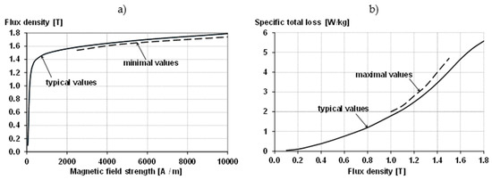
Figure 1.
Guaranteed (minimal) and typical magnetizability (a) and specific total loss (b) of electrical sheet M470-50A at 50 Hz, according to European Standard EN 10106.
Figure 2 shows the catalog characteristics of the M270-35A sheet magnetizability and loss.
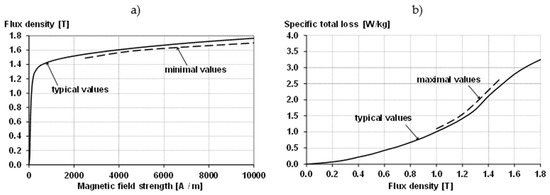
Figure 2.
Guaranteed (minimal) and typical magnetizability (a) and specific total loss (b) of electrical sheet M270-35A at 50 Hz, according to European Standard EN 10106.
Figure 3 shows a comparison of the catalog magnetizability and loss characteristics for 50 Hz and 400 Hz of M470-50A and M270-35A sheets.
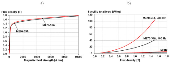
Figure 3.
Typical magnetic polarization at 50 Hz (a) and specific total loss (b) of electrical sheets M470-50A and M270-35A, according to European Standard EN 10106.
To assess the influence of the punching technology on the parameters of the sheet, measurements of the magnetizability and loss characteristics were made for samples of different widths, cut at different angles in relation to the rolling direction of the sheet, using three punching technologies.
3. Applied Measurement Method and Its Range
Measurements were made using the SST system designed to measure the dynamic magnetic properties of strips, with a length of 300 mm and a width of 60 mm. The measurement accuracy meets the requirements of IEC standards for measurement conditions. Due to the construction of the measuring yoke, ensuring free air flow around the tested strips, as well as relatively low power loss and a short measurement time, it was considered the temperature of the tested strips was practically constant, i.e., room temperature. The measuring system is shown in Figure 4.
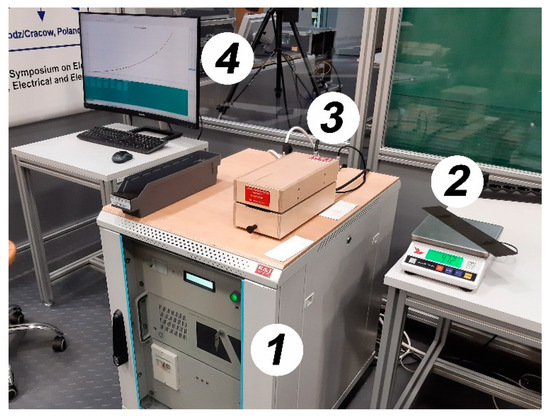
Figure 4.
Experimental setup for testing laminations’ parameters; 1—power electronic module, 2—weighing machine with the tested strip, 3—measurement yoke, 4—LCD of the measuring computer.
Indirect or direct methods can measure magnetic field intensity. The direct measurement of magnetic field intensity is carried out using a measuring coil placed in the immediate vicinity of the tested strip. This method applies the law of the continuity of the tangential magnetic field intensity on the ferromagnetic–air boundary surface. The used SST system allows for determining, among others, the B-H curve, specific iron loss of the test material, and the dynamic hysteresis loop. Measurements can be carried out in a strictly defined operating range, characterized by flux density and frequency.
The SST system applies the shaping of an induction course to be sinusoidal as close as possible, with an accuracy of 0.1% for Bm greater than 0.9 T and 0.5% for Bm less than 0.9 T. The specimen’s demagnetization is taken into account in the measurement procedure. Together with the calibration procedure, the whole measuring process is fully automated, controlled by the tool software. All measurement results are saved in files, which can then be analyzed in this system or any other tool software.
The specific iron loss of the material tested is determined according to the dependence
where p is a specific iron loss, in W/kg; mfe is a weighted sample mass (determined for a length of 265 mm), in kg; z1 is a number of coils in the magnetizing winding; z2 is a number of coils in measuring winding; T is a period of sinusoidal induction curve, in seconds; u(t) is a course of a voltage, in V, induced in measuring winding; im(t) is a course of a current, in A, flowing in the magnetizing winding
The course of the induction averaged over the specimen area was determined according to the relationship
where B(t) is a course of average induction, in T; S is an area of the test strip, in m2; e(t) is an electromotive force, in V, induced in the measuring winding.
In the case of indirect determination of magnetic field intensity, the following dependence was used
where Ht(t) is a course of tangential (to the strip) component of magnetic field intensity, in A/m; zb is the number of coils in the winding measuring the signal proportional to the tangential component of magnetic field intensity; Sb is an area enclosed by the above mentioned winding, in m2; ub is a voltage induced in this winding, in V.
In the case of indirect determination of magnetic field intensity, the following dependence was used
where H(t) is a course of magnetic field intensity, in A/m; zm is the number of coils in the magnetizing winding; l is the length of the magnetic way in the specimen (assumed as 0.265 m), in m; R is the resistance of the shunt leading magnetizing current, in Ohm; uR(t) is a voltage drop over this shunt, in V.
In the SST system used, rectangular shape specimens were tested. They had a length of 300 mm, and widths changed from 4 mm to 60 mm. In the case of specimens characterized by widths less than 60 mm, several strips with a smaller width were used to reach the total dimension of 60 mm. For example, for 10 mm wide specimens, six samples were studied at the same time, reaching a total width of 60 mm. The test specimens were cut using three commonly used technologies: guillotine cutting (which corresponds to the widely used technology shaping electrical core), laser, and water cutting. The specimens cut by water jet had a width of 60 mm solely. Due to a relatively small negative effect of cutting on the material properties’ change, they were considered reference specimens. A series of measurements were executed considering the cutting angle in relation to the rolling direction. The specimens tested were cut at an angle of 0, 30, 45, 60, and 90 degrees in relation to the rolling direction. In the test strips, the external magnetic field vector was always directed along the longest side of the strip, i.e. a side of 300 mm long. For measurements carried out at specific cut angles, the rectangular strip was cut at the specified angle from the larger sheet.
4. Influence of the Width and Angle of Sample Cutting on the Magnetizability and Loss Characteristics of Electrical Sheets
When calculating the magnetizing current and losses in electrical machines, an important role is played by the B-H curve and the losses of the electrical sheet from which the machine core is made. The characteristics provided by the producers of these sheets, most often determined with the use of Epstein’s apparatus, refer to the average physical quantities and do not take into account the influence of their cutting angles in relation to the rolling direction of the sheet. For this reason, the B-H curve and losses were measured for samples with a width of 30 mm (sample width in an Epstein apparatus) and samples with a width of 4, 5, 7, 10, 15, 20, 30, and 60 mm cut with a guillotine at an angle of 0, 30, 45, 60, and 90 degrees in relation to the rolling direction, made of two types of electrical sheet: M470-50A with a thickness of 0.5 mm and M270-35A with a thickness of 0.35 mm; then, the average characteristics for all angles and only for the angles 0 and 90 degrees were determined.
4.1. Influence of the Sample Cutting Width and Angle on the Magnetizability Characteristics
Figure 5 shows an example of the measured magnetization characteristics of the M470-50A sheet with a thickness of 0.5 mm for samples with a width of 5 mm cut with a guillotine at different cutting angles in relation to the rolling direction of the sheet, for frequencies of 50 Hz and 2000 Hz.
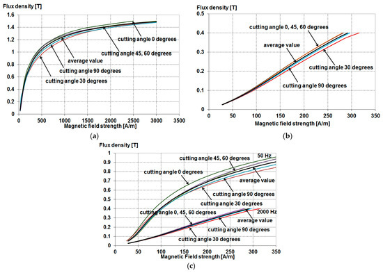
Figure 5.
The measured magnetization characteristics for M470-50A sheet for samples 5 mm wide, cut with a guillotine at different cutting angles and the average characteristics for all angles, for the frequency 50 Hz (a), 2000 Hz (b) and both frequencies on one graph (c).
As shown in Figure 5, the influence of the sample cutting angle on the magnetization characteristics is small (not exceeding 4% according to the mean value in the range of magnetic field strength from 1000 to 2500 A/m at the frequency of 50 Hz). At the frequency of 2000 Hz, the relative deviation in flux density for the mean values in the range of magnetic field strength from 40 to 280 A/m does not exceed 7%, which indicates the possibility of using the averaged magnetization characteristic for this frequency. Thus, in practice, it is possible to use the average characteristic, determined either for all cutting angles or for 0 and 90 degrees angles with respect to the rolling direction of the sheet. Later in the article, the magnetization characteristics averaged for all angles are presented. Figure 6 presents examples of the measured average for all angles of the M470-50A sheet’s magnetization characteristics with a thickness of 0.5 mm for samples cut with a guillotine of various widths, for frequencies of 50 Hz and 2000 Hz.
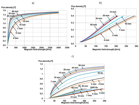
Figure 6.
The measured average for all angles of the M470-50A sheet’s magnetization characteristics for frequencies of 50 Hz (a) and 2000 Hz (b) and both frequencies on one graph (c).
Based on Figure 6, it can be concluded that the magnetization characteristics strongly depend on the width of the sample and deteriorate with the reduction in the sample width, especially in the range of smaller induction. These discrepancies increase with increasing frequency. The observed phenomenon results from the destruction of a part of the material structure. For a frequency of 50 Hz, it can be assumed that the characteristics will converge for increasing induction values.
The magnetization characteristics measured and averaged for all angles (solid line) and 0 and 90 degrees (dashed line) for both types of sheets for different frequencies (50, 350, 1000, and 2000 Hz) are given in Figure 7, Figure 8, Figure 9 and Figure 10. Figure 7 shows typical catalog magnetization characteristics, determined according to European Standard EN 10106, for comparison.
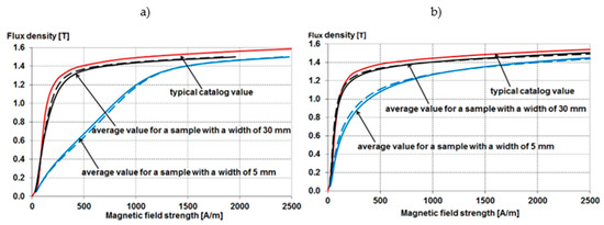
Figure 7.
The magnetization characteristics for 50 Hz for samples cut with a guillotine 5 mm and 30 mm wide for M470-50A (a) and M270-35A (b); characteristics averaged for all angles (solid line) and 0 and 90 degrees (dashed line).
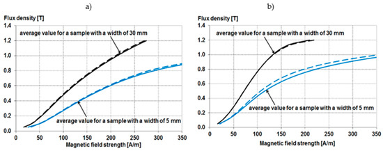
Figure 8.
The magnetization characteristics for 350 Hz for samples cut with a guillotine 5 mm and 30 mm wide for M470-50A (a) and M270-35A (b); characteristics averaged for all angles (solid line) and 0 and 90 degrees (dashed line).
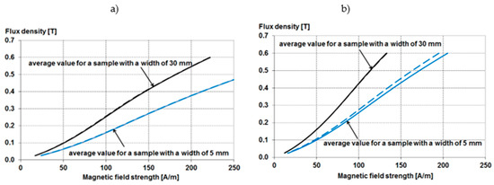
Figure 9.
The magnetization characteristics for 1000 Hz for samples cut with a guillotine 5 mm and 30 mm wide for M470-50A (a) and M270-35A (b); characteristics averaged for all angles (solid line) and 0 and 90 degrees (dashed line).
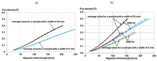
Figure 10.
The magnetization characteristics for 2000 Hz for samples cut with a guillotine 5 mm and 30 mm wide for M470-50A (a) and M270-35A (b); characteristics averaged for all angles (solid line) and 0 and 90 degrees (dashed line).
As shown in Figure 7, Figure 8, Figure 9 and Figure 10, for samples with a larger width, the magnetizability characteristics averaged for all angles practically coincide with the average characteristics determined for 0 and 90 degrees angles. Slight discrepancies between these characteristics occur for samples with a small width, and they are more significant the smaller the thickness of the sheet.
Reducing the thickness of the electrical sheet also significantly worsens the magnetization characteristics, especially in the range of small induction values. That is particularly important when the electric machine operates at a high frequency when the induction in the machine core is much lower than when operating at 50/60 Hz frequency.
The magnetization characteristics deteriorate further with increasing frequency. The obtained results indicate that when calculating the electromagnetic parameters of electric machines, it is sufficient to use the family of the magnetization characteristics averaged for the angles 0 and 90 degrees, determined for samples of different thicknesses, corresponding to the thickness of the magnetic circuit elements of the machine at different frequencies. The use of typical catalog characteristics in such calculations, which are determined for one sample width, may result in erroneous values of the magnetizing current, which, especially in low-power motors, may exceed 70% of the rated current and, consequently, has a significant impact on the power losses in the machine windings.
4.2. Influence of the Sample Width and Cutting Angle on the Loss Characteristics
Figure 11 shows an example of the measured loss characteristics of the M470-50A sheet with a thickness of 0.5 mm for samples with a width of 5 mm cut with a guillotine at different cutting angles in relation to the rolling direction of the sheet, for frequencies of 50 Hz and 2000 Hz.
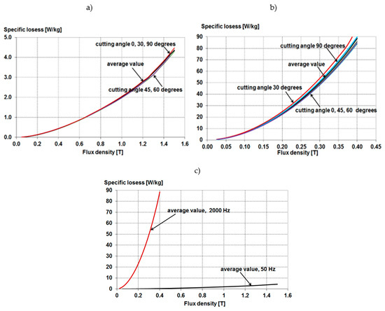
Figure 11.
Specific losses of M470-50A sheet for samples 5 mm wide, cut with a guillotine at different cutting angles and average characteristics for all angles, for frequencies of 50 Hz (a) and 2000 Hz (b) and both frequencies on one graph (c).
Based on Figure 11, it can be concluded that also the specific losses characteristics for different cutting angles in relation to the rolling direction of the sheet at the mains frequency are practically the same, while even at the frequency of 2000 Hz, they are very close to each other; so when determining the efficiency characteristics, the sample cutting angle is practically identical. This does not matter, and also, in this case, you can use the averaged characteristic, determined for all angles or only for 0 and 90 degrees.
Figure 12 shows examples of the measured average for all angles of the specific losses’ characteristics of the M470-50A sheet with a thickness of 0.5 mm for samples cut with a guillotine of different widths for frequencies of 50 Hz and 2000 Hz.
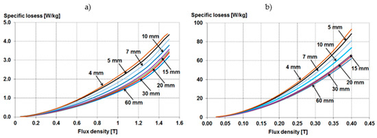
Figure 12.
The average specific losses of M470-50A sheet for samples of different widths cut with a guillotine, for frequencies of 50 Hz (a) and 2000 Hz (b).
As can be seen from Figure 12, the specific losses’ characteristics significantly depend on the width of the sample, and they increase with the increase in induction and frequency as well as with the decrease in the sample thickness, which can be explained by the increasing influence of the width of the damaged layer as the width of the sample decreases.
The loss characteristics for both steel grades for different frequencies (50, 350, 1000, and 2000 Hz) are measured and averaged for all solid line angles and 0 and 90 degree angles (dashed line). Figure 13, Figure 14, Figure 15 and Figure 16 are shown. Figure 13 and Figure 15 show the typical catalog loss value for comparison, determined according to European Standard EN 10106.
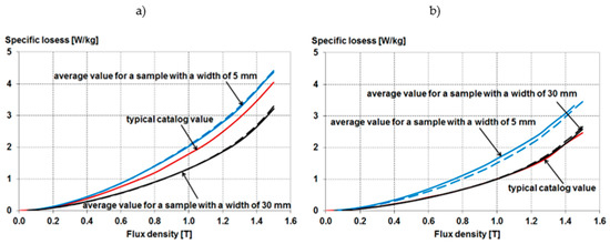
Figure 13.
The specific losses at 50 Hz for samples cut with a guillotine 5 mm and 30 mm wide, made of electrical sheet M470-50A (a) and M270-35A (b); characteristics averaged for all angles (solid line) and 0 and 90 degrees (dashed line).
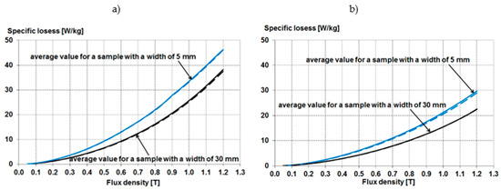
Figure 14.
The specific losses at 350 Hz for samples cut with a guillotine 5 mm and 30 mm wide, made of electrical sheet M470-50A (a) and M270-35A (b); characteristics averaged for all angles (solid line) and 0 and 90 degrees (dashed line).
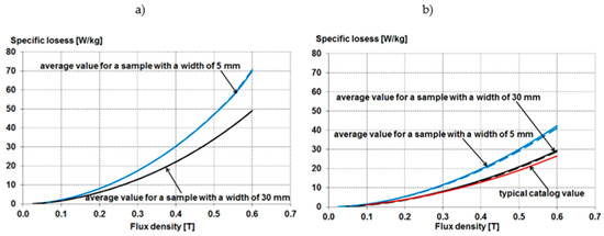
Figure 15.
The specific losses at 1000 Hz for samples cut with a guillotine 5 mm and 30 mm wide, made of electrical sheet M470-50A (a) and M270-35A (b); characteristics averaged for all angles (solid line) and 0 and 90 degrees (dashed line).
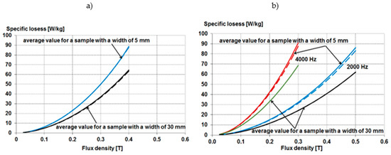
Figure 16.
The specific losses at 2000 Hz for samples cut with a guillotine 5 mm and 30 mm wide, made of electrical sheet M470-50A (a) and M270-35A (b); characteristics averaged for all angles (solid line) and 0 and 90 degrees (dashed line).
As can be seen from Figure 13, Figure 14, Figure 15 and Figure 16, similarly to the magnetizability characteristics, for samples with a larger width, the specific losses’ characteristics averaged for all angles practically coincide with the average characteristics for 0 and 90 degrees angles. Certain discrepancies between these characteristics occur for samples of small width, especially for thinner sheet metal. Still, they are so slight that, in practice, the influence of the sample cutting angle can be neglected when determining the loss curve. However, the width of the samples is essential as it should correspond to the width of the individual elements of the machine’s magnetic circuit.
Reducing the thickness of the electrical sheet reduces its losses, but when selecting sheets used for the core of an electric machine, technological and economic limitations should be considered in this regard.
The results of measurements of the loss characteristics for the M270-35A sheet for samples with a width of 30 mm practically coincide with the catalog characteristics determined for samples of the same width in the Epstein apparatus. Still, for the M470-50A sheet, there are significant discrepancies in this range, which may cause erroneous results of calculations of losses in the core of an electric machine made of this type of sheet metal.
5. Influence of the Sample Cutting Technology on the Characteristics of Magnetizability and Loss of Electrical Sheet
When making samples from M470-50A sheet metal, three cutting technologies were used: water, which is the least invasive technology, a guillotine, which in practice corresponds to industrial core punching with a punch, and a laser, which is used for punching the machine core’s model and atypical individual product. The authors are aware that the condition of the guillotine blades and laser cutting parameters affect the material parameters of the damaged area. Therefore, when preparing the samples, a guillotine was used in which, after installing new cutting knives, it made 1000 initial cutting cycles, and then test samples were prepared. In the case of laser cutting, the cutting speed, laser power, and nitrogen pressure were assumed as 240 mm/s, 3 kW, and 10 bar, respectively.
The magnetization characteristics of the M470-50A sheet with a thickness of 0.5 mm for samples cut by laser, for the frequency of 50 Hz, are shown in Figure 17, while Figure 17a shows the magnetization characteristics of 5 mm wide samples cut at different angles in relation to the rolling direction; Figure 17b shows the average for all magnetization angles for samples of different widths.
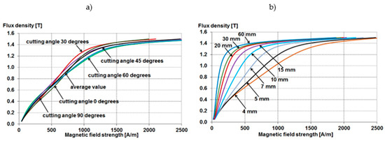
Figure 17.
The magnetization characteristics of M470-50A sheet for samples cut with a laser with a width of 5 mm at various cutting angles (a) and average magnetization characteristics for samples of various widths (b), for the frequency of 50 Hz.
As can be seen from Figure 17, also when cutting samples with a laser, the influence of sheet anisotropy to a minimal extent affects the magnetization characteristics. In contrast, these characteristics strongly depend on the width of the sample, while the influence of the width of the damaged zone at the edges of the sample is, in this case, more significant than when punching with a die.
The magnetization characteristics measured and averaged for all angles (solid line) and 0 and 90 degrees (dashed line) for samples made of the M470-50A sheet with various laser-cut widths, for frequencies of 50 and 2000 Hz, are shown in Figure 18.
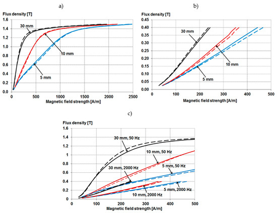
Figure 18.
The magnetization characteristics for 5 mm, 10 mm, and 30 mm wide laser-cut samples made of M470-50A electrical sheet at 50 Hz (a) and 2000 Hz (b) and both frequencies on one graph (c); characteristics averaged for all angles (solid line) and 0 and 90 degrees (dashed line).
Moreover, when using this punching technology, at 50 Hz frequency, the magnetization characteristics averaged for all angles practically coincide with the average characteristics for 0 and 90 degrees angles. Slightly greater discrepancies between these characteristics occur at the frequency of 2000 Hz, especially for samples with a smaller width.
Figure 19 shows a comparison of the averaged magnetization characteristics for all angles for samples with a width of 5, 15, and 60 mm, made of the M470-50A electrical sheet, cut with a guillotine and laser, at 50 Hz and 2000 Hz. The average magnetization characteristics for a 60 mm wide sample cut with water are also given. This technology causes virtually no damage at the cut edges, so this characteristic can be considered the magnetization characteristic for an undamaged sample.
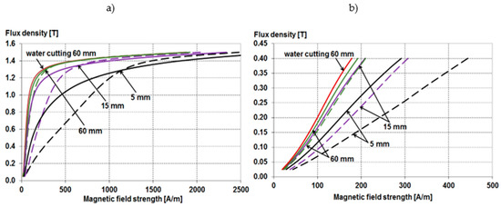
Figure 19.
Average for all angles magnetization characteristics for samples cut with a guillotine (solid line) and laser (dashed line) with a width of 5, 15, and 60 mm, made of electrical sheet M470-50A, at 50 Hz (a) and 2000 Hz (b).
As shown in Figure 19, the influence of the cutting technology on the magnetization characteristics is considerable. It increases with the reduction in the sample width and the frequency increase.
Figure 20 shows the averaged loss characteristics at frequencies of 50 Hz and 2000 Hz for samples of different widths made of M470-50A sheet metal, cut using other technologies. Additionally, in this case, the loss characteristics are given for a 60 mm wide sample cut with water.
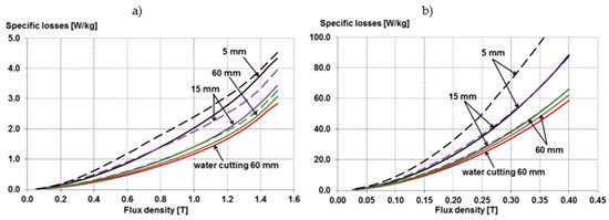
Figure 20.
Average for all angles of the specific losses’ characteristics for samples cut with a guillotine (solid line) and laser (dashed line) with a width of 5, 15, and 60 mm made of M470-50A electrical sheet, at 50 Hz (a) and 2000 Hz (b).
As can be seen from Figure 20, for a sample with a width of 60 mm, the impact of the cutting technology on the performance characteristics, regardless of the frequency, is relatively small because the width of the damaged part in relation to the width of the sample is insignificant. A significant increase in loss occurs for laser-cut samples as the sample width decreases and the frequency increases.
6. Determination of Equivalent Averaged Magnetization and Loss Characteristics for Samples of Different Width
Under the influence of punching, a degraded part of the material is created, which is characterized by much worse parameters: worse magnetizability and greater loss. The width of the degraded zone is dependent on many factors, including both the properties of the sheet and the properties of the tool, such as clearance and the condition of the punch blade. The tool parameters change during the punching process, which affects the degradation effect of the electrical sheet part. Degradations of the edge appearing during cutting are all types of damage, such as: grain fracture, additional dislocations of the crystallographic lattice, and phase and chemical changes in the material as well as internal stresses caused by the cutting process. Each of these components changes the material characteristics in its own way, at the distance from the cut edge, measured in μm or mm. Determining the width of the degraded layer is difficult. The papers [13,39] present an extensive review of various methods of determining the width of a degraded layer. Depending on the method used, this width varies from a part of a millimeter to a few millimeters. In turn, the work [40] proposes a method of estimating the width of the degraded zone based on measurements for sheets of different widths. The introduction of dependencies describing the change in magnetizability and loss for the material subjected to punching is essential for the correct determination of the resulting efficiency of the electric motor and other devices [41,42,43,44]. The way of presenting these dependencies is also essential, mainly in terms of their use in a quick analytical model. Based on these data, the authors assumed that, as shown in Figure 21, the sheet with the width w can be divided into two regions: degraded with a width of 2a and non-degraded with a width (w-2a).
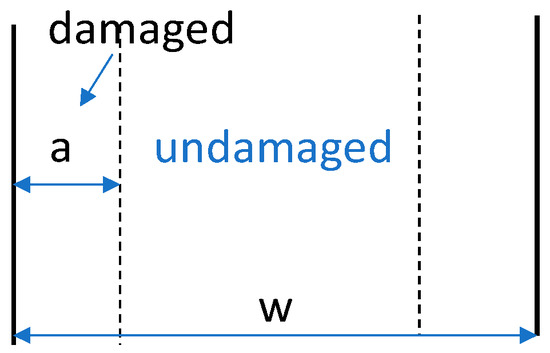
Figure 21.
Electrical sheet punching effect.
If we assume that the magnetic field strength vector H has a direction along the length of the sample, then the modulus H is constant across the width of the sample. Hence, for a given value of H, we can calculate the mean value of the induction across the width of the sample (Figure 22).
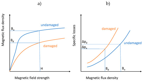
Figure 22.
Characteristics of magnetization (a) and loss (b) of undamaged and damaged electrical sheet due to punching.
According to Figure 21 and Figure 22, we can calculate the value of the magnetic induction in a strip of sheet width w based on the relationship
where H is the magnetic field strength in the sample, Bw is the average magnetic flux density for a sample of width w, Bd is the magnetic flux density for magnetic field strength H in damaged material, Bu is the magnetic flux density for magnetic field strength H in undamaged material.
Then, knowing the magnetic flux density values in the damaged and undamaged parts, we can calculate the average specific losses for a sheet with a width of w
where Δpd is the specific losses determined for a damaged sample (4 mm wide) for flux density Bd, and Δpd is the specific losses determined for an undamaged sample for flux density Bu.
Due to the measurement possibilities and the literature indications, it was assumed that a sample cut with a die cut with the smallest width of 4 mm is a sample representing completely damaged material, while the characteristics for undamaged material were adopted for a sample cut with water 60 mm wide.
Figure 23, Figure 24, Figure 25 and Figure 26 show the characteristics for the M470-50A50 and M270-35A50 electrical sheets for 50 Hz and Figure 27 and Figure 28 show the characteristics for the M470-50A50 and M370-35A50 electrical sheets for 2000 Hz. Only the loss characteristics were investigated because they are used to determine the core loss for higher harmonics.
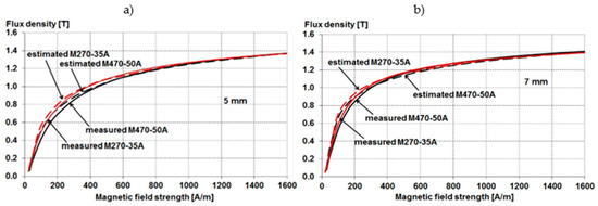
Figure 23.
Measured (solid) and calculated (dashed) magnetization characteristics of a sample 5 mm (a) and 7 mm (b) wide, punched with a die made of M470-50A and M270-35A sheets for a frequency of 50 Hz.
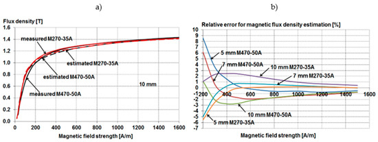
Figure 24.
Measured (solid) and calculated (dashed) magnetization characteristics of a sample 10 mm (a) punched with a die made of M470-50A and M270-35A sheets for a frequency of 50 Hz and relative error for magnetic flux density estimation (b).
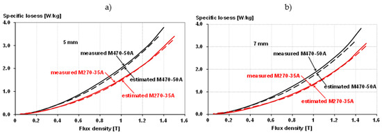
Figure 25.
Measured (solid) and calculated (dashed) the specific losses of a sample 5 mm (a) and 7 mm (b) wide, punched with a die made of M470-50A and M270-35A sheets for a frequency of 50 Hz.
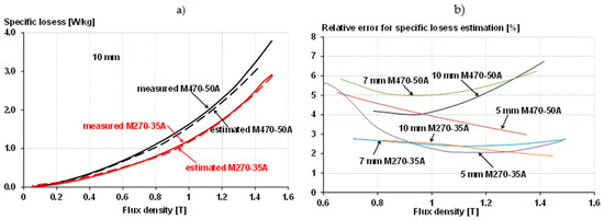
Figure 26.
Measured (solid) and calculated (dashed) the specific losses of a sample 10 mm wide, punched with a die made of M470-50A and M270-35A sheets for a frequency of 50 Hz (a) and relative error for the specific losses estimation (b).
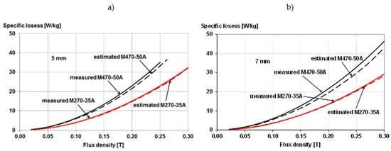
Figure 27.
Measured (solid) and calculated (dashed) the specific losses of a sample 5 mm (a) and 7 mm (b) wide, punched with a die made of M470-50A and M270-35A sheets for a frequency of 2000 Hz.
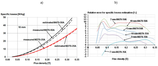
Figure 28.
Measured (solid) and calculated (dashed) the specific losses of a sample 10 mm wide, punched with a die made of M470-50A and M270-35A sheets for a frequency of 2000 Hz (a) and relative error for the specific losses estimation (b).
As can be seen from Figure 23, Figure 24, Figure 25, Figure 26, Figure 27 and Figure 28, the maximum relative error in estimating both the magnetization and loss characteristics for samples of various widths does not exceed 10%. In the case of the magnetization characteristics, it is the largest for small values of the magnetic induction. In the case of the induction commonly occurring in the core of the electric machine (most often exceeding 1.2 T), this error does not exceed 2%. In the case of the loss characteristics, this error increases with the increase in both the induction and the width of the sample, but also in this case, for an induction of 1.6 T, it does not exceed 10% for 50 Hz and 12% for 2000 Hz. The presented figures show that better estimation accuracy is obtained for the sheet M270-35A of lower thickness. We observe this for both the magnetization characteristics and the loss characteristics.
Of course, the adopted model is simplified, which results in an estimation error that increases for larger sheet widths. This is probably because the damaging mechanism of the sheet is more complicated. As mentioned, the width of the damaged layer is uncertain. Point measurements are debatable because the measurement methods themselves disturb local properties. Indirect measurements of mechanical properties or the crystallographic structure also do not provide unambiguous information. This problem will therefore be the subject of further research.
7. Conclusions
The measurement results presented in the paper confirm that punching has a significant impact on the material properties of electric machine cores: magnetizability and loss.
As a result of the production process, quasi-isotropic sheets (often referred to as non-oriented) are characterized by magnetic anisotropy. Based on the obtained measurement results, it was found that the average characteristics obtained for samples cut at different angles in relation to the rolling direction of the sheet do not differ much from the averaged characteristics for samples cut at an angle of 0 and 90 degrees. It was also found that the process of preparing samples with small widths (4–5 mm) cut with a guillotine at different angles should be carefully carried out, which may affect the course of their magnetizing characteristics.
Moreover, a simplified method of determining substitute material characteristics for samples of different widths was proposed based on the measurement results obtained for a sample with a small width (not exceeding 4 mm), cut with a die, and the sample with a width of 60 mm, cut with water. It was verified by measurement for samples with a width not exceeding 10 mm (which corresponds to the dimensions of the magnetic core elements of low and medium power motors), mechanically cut for frequencies of 50 Hz and 2000 Hz, made of both M470-50A sheets with a thickness of 0.5 mm and from M270-35A sheets with a thickness of 0.35 mm.
The aim of further works by the authors will be to adapt the so far developed methods for determining substitute material characteristics for samples of various dimensions, made with various punching methods, for a wide range of frequencies.
The research works carried out by the authors are aimed at developing a rapid method for determining the material characteristics of the sheets used in the construction of general purpose machine cores, taking into account the negative effects resulting from the applied shaping process. As shown by the results of calculations and simulations, the proposed method can be effectively applied to classic motor designs, not intended for operation in special conditions, e.g., at elevated temperature, resulting from environmental conditions or the density of power losses in the core.
Author Contributions
Conceptualization, M.D., K.K. and Z.G.; methodology, M.D., K.K. and Z.G.; software, M.D. and J.S.; validation, J.S. and Z.G.; formal analysis, M.D. and K.K.; investigation, J.S. and Z.G.; resources, M.D.; data curation, M.D. and Z.G.; writing—original draft preparation, M.D. and K.K.; writing—review and editing, M.D., K.K. and Z.G.; supervision, M.D., K.K. and Z.G.; project administration, M.D.; funding acquisition, M.D. All authors have read and agreed to the published version of the manuscript.
Funding
This research was funded by National Science Centre (NCN) Poland as part of the Opus–18’, grant number 2019/35/B/ST8/00764 ‘The manufacturing technology impact analysis of small-power high-speed electric motors to refine their analytical models’.
Institutional Review Board Statement
Not applicable.
Informed Consent Statement
Not applicable.
Data Availability Statement
Data available on request due to research founder restrictions.
Conflicts of Interest
The authors declare no conflict of interest.
References
- Waide, P.; Brunner, C.U. Energy-Efficiency Policy Opportunities for Electric Motor-Driven Systems. In International Energy Agency: IEA Energy Papers; No. 2011/07; OECD Publishing: Paris, France, 2011. [Google Scholar] [CrossRef]
- Bramerdorfer, G.; Lei, G.; Cavagnino, A.; Zhang, Y.; Sykulski, J.; Lowther, D.A. More Robust and Reliable Optimized Energy Conversion Facilitated through Electric Machines, Power Electronics and Drives, and Their Control: State-of-the-Art and Trends. IEEE Trans. Energy Convers. 2020, 35, 1997–2012. [Google Scholar] [CrossRef]
- Cavagnino, A.; Vaschetto, S.; Ferraris, L.; Gmyrek, Z.; Agamloh, E.B.; Bramerdorfer, G. Striving for the Highest Efficiency Class with Minimal Impact for Induction Motor Manufacturers. IEEE Trans. Ind. Appl. 2019, 56, 194–204. [Google Scholar] [CrossRef]
- Fortunati, S.; Cicalé, S.; Schneider, J.; Franke, A. Developments in the Field of Electrical Steels over the Last Years. In Proceedings of the International Conference on Magnetism and Metallurgy—WMM16 Proceedings, Rome, Italy, 13–15 June 2016; p. 29. [Google Scholar]
- Siebert, R.; Baumann, R.; Beyer, E.; Herwig, P.; Wetzig, A. Laser manufacturing of electrical machines. In Proceedings of the 2014 4th International Electric Drives Production Conference (EDPC), Nuremberg, Germany, 30 September–1 October 2014; pp. 1–5. [Google Scholar] [CrossRef]
- Sundaria, R.; Nair, D.G.; Lehikoinen, A.; Arkkio, A.; Belahcen, A. Effect of Laser Cutting on Core Losses in Electrical Machines—Measurements and Modeling. IEEE Trans. Ind. Electron. 2019, 67, 7354–7363. [Google Scholar] [CrossRef]
- Hofmann, M.; Naumoski, H.; Herr, U.; Herzog, H.-G. Magnetic Properties of Electrical Steel Sheets in Respect of Cutting: Micromagnetic Analysis and Macromagnetic Modeling. IEEE Trans. Magn. 2016, 52, 15720341. [Google Scholar] [CrossRef]
- Nemoianu, I.-V.; Paltanea, V.M.; Paltanea, G.; Dascalu, M.-I.; Ciuceanu, R.M. Electric motors of large consumer products, challenges and trends from the perspective of power efficiency improvement through modern cutting technologies. In Proceedings of the 2019 Zooming Innovation in Consumer Technologies Conference (ZINC), Novi Sad, Serbia, 29–30 May 2019; 2019; pp. 76–81. [Google Scholar]
- Paltanea, V.M.; Paltanea, G.; Gavrila, H.; Nemoianu, I.V.; Andrei, P.C. Magnetic properties degradation due to the cutting procedures in the case of electrical steel used in energy efficient electrical machines. In Proceedings of the 2017 Electric Vehicles International Conference (EV), Băile Govora, Romania, 8–10 November 2017; pp. 1–4. [Google Scholar]
- Schoppa, A.; Louis, H.; Pude, F.; von Rad, C. Influence of abrasive waterjet cutting on the magnetic properties of non-oriented electrical steels. J. Magn. Magn. Mater. 2003, 254–255, 370–372. [Google Scholar] [CrossRef]
- Emura, M.; Landgraf, F.; Ross, W.; Barreta, J. The influence of cutting technique on the magnetic properties of electrical steels. J. Magn. Magn. Mater. 2003, 254-255, 358–360. [Google Scholar] [CrossRef]
- Tiismus, H.; Kallaste, A.; Vaimann, T.; Rassolkin, A.; Belahcen, A. Electrical Resistivity of Additively Manufactured Silicon Steel for Electrical Machine Fabrication. In Proceedings of the 2019 Electric Power Quality and Supply Reliability Conference (PQ) & 2019 Symposium on Electrical Engineering and Mechatronics (SEEM), Kardla, Estonia, 12–15 June 2019; pp. 1–4. [Google Scholar] [CrossRef] [Green Version]
- Bali, M.; Muetze, A. The Degradation Depth of Non-grain Oriented Electrical Steel Sheets of Electric Machines Due to Mechanical and Laser Cutting: A State-of-the-Art Review. IEEE Trans. Ind. Appl. 2018, 55, 366–375. [Google Scholar] [CrossRef]
- Manescu-Paltanea, V.; Paltanea, G.; Nemoianu, I.V. Degradation of Static and Dynamic Magnetic Properties of Non-Oriented Steel Sheets by Cutting. IEEE Trans. Magn. 2018, 54, 18164379. [Google Scholar] [CrossRef]
- Bourchas, K.; Stening, A.; Soulard, J.; Broddefalk, A.; Lindenmo, M.; Dahlen, M.; Gyllensten, F. Quantifying Effects of Cutting and Welding on Magnetic Properties of Electrical Steels. IEEE Trans. Ind. Appl. 2017, 53, 4269–4278. [Google Scholar] [CrossRef] [Green Version]
- Weiss, H.A.; Trober, P.; Golle, R.; Steentjes, S.; Leuning, N.; Elfgen, S.; Hameyer, K.; Volk, W. Impact of Punching Parameter Variations on Magnetic Properties of Nongrain-Oriented Electrical Steel. IEEE Trans. Ind. Appl. 2018, 54, 5869–5878. [Google Scholar] [CrossRef]
- Gmyrek, Z.; Cavagnino, A. Analytical Model of the Ferromagnetic Properties in Laminations Damaged by Cutting. In Proceedings of the 2021 IEEE Energy Conversion Congress and Exposition (ECCE), Virtual, 10–14 October 2021; pp. 4000–4007. [Google Scholar] [CrossRef]
- Daem, A.; Sergeant, P.; Dupré, L.; Chaudhuri, S.; Bliznuk, V.; Kestens, L. Magnetic Properties of Silicon Steel after Plastic Deformation. Materials 2020, 13, 4361. [Google Scholar] [CrossRef]
- Füzer, J.; Dobák, S.; Petryshynets, I.; Kollár, P.; Kováč, F.; Slota, J. Correlation between Cutting Clearance, Deformation Texture, and Magnetic Loss Prediction in Non-Oriented Electrical Steels. Materials 2021, 14, 6893. [Google Scholar] [CrossRef]
- Wang, W.; Fang, X.; Wang, X.; Andrieux, M.; Ji, V. Mechanism of Blunt Punching Tools’ Influence on Deformation and Residual Stress Distribution. Metals 2021, 11, 2029. [Google Scholar] [CrossRef]
- Gontarz, S.; Szulim, P.; Patyk, R.; Bohdal, L. Multiparameter Modeling and Analysis of Mechanical Cutting Process of Grain-Oriented Silicon Steel. IEEE Magn. Lett. 2021, 12, 21399771. [Google Scholar] [CrossRef]
- Bohdal, Ł.; Patyk, R.; Tandecka, K.; Gontarz, S.; Jackiewicz, D. Influence of shear-slitting parameters on workpiece formation, cut edge quality and selected magnetic properties for grain-oriented silicon steel. J. Manuf. Process. 2020, 56, 1007–1026. [Google Scholar] [CrossRef]
- Saleem, A.; Alatawneh, N.; Rahman, T.; Lowther, D.A.; Chromik, R.R. Effects of Laser Cutting on Microstructure and Magnetic Properties of Non-Orientation Electrical Steel Laminations. IEEE Trans. Magn. 2020, 56, 14236932. [Google Scholar] [CrossRef]
- Regnet, M.; Kremser, A.; Reinlein, M.; Szary, P.; Abele, U. Influence of Cutting Tool Wear on Core Losses and Magnetizing Demand of Electrical Steel Sheets. In Proceedings of the 2019 9th International Electric Drives Production Conference (EDPC), Esslingen, Germany, 3–4 December 2019; pp. 1–6. [Google Scholar] [CrossRef]
- Sundaria, R.; Nair, D.G.; Lehikoinen, A.; Arkkio, A.; Belahcen, A. Loss Model for the Effects of Steel Cutting in Electrical Machines. In Proceedings of the 2018 XIII International Conference on Electrical Machines (ICEM), Alexandroupoli, Greece, 3–6 September 2018; pp. 1260–1266. [Google Scholar] [CrossRef] [Green Version]
- Paltanea, V.M.; Paltanea, G.; Gavrila, H. Some important effects of the water jet and laser cutting methods on the magnetic properties of the non-oriented silicon iron sheets. In Proceedings of the 2015 9th International Symposium on Advanced Topics in Electrical Engineering (ATEE), Bucharest, Romania, 7–9 May 2015; pp. 452–455. [Google Scholar] [CrossRef]
- Manescu-Paltanea, V.; Paltanea, G.; Nemoianu, I.-V. Influence of edge mechanical stress on the 50 Hz magnetic properties of thin electrical steel. In Proceedings of the 2017 International Conference on Optimization of Electrical and Electronic Equipment (OPTIM) & 2017 Intl Aegean Conference on Electrical Machines and Power Electronics (ACEMP), Bran, Romania, 25–27 May 2017; pp. 450–455. [Google Scholar] [CrossRef]
- Paltanea, G.; Paltanea, V.M.; Helerea, E.; Nemoianu, I.-V.; Calin, M.D. Cutting Technologies Influence on Magnetic Properties of Electrical Steels used in High-Efficiency Motors Manufacturing. In Proceedings of the 2019 International Aegean Conference on Electrical Machines and Power Electronics (ACEMP) & 2019 International Conference on Optimization of Electrical and Electronic Equipment (OPTIM), Istanbul, Turkey, 27–29 August 2019; pp. 166–171. [Google Scholar] [CrossRef]
- Paltanea, G.; Manescu, V.; Stefanoiu, R.; Nemoianu, I.V.; Gavrila, H. Correlation between Magnetic Properties and Chemical Composition of Non-Oriented Electrical Steels Cut through Different Technologies. Materials 2020, 13, 1455. [Google Scholar] [CrossRef] [PubMed] [Green Version]
- Cossale, M.; Kitzberger, M.; Goldbeck, G.; Bramerdorfer, G.; Andessner, D.; Amrhein, W. Local Degradation in Soft Magnetic Materials: A Simplified Modeling Approach. IEEE Trans. Ind. Appl. 2019, 55, 5897–5905. [Google Scholar] [CrossRef]
- Araujo, E.G.; Schneider, J.; Verbeken, K.; Pasquarella, G.; Houbaert, Y. Dimensional Effects on Magnetic Properties of FeSi Steels Due to Laser and Mechanical Cutting. IEEE Trans. Magn. 2010, 46, 213–216. [Google Scholar] [CrossRef] [Green Version]
- Leuning, N.; Steentjes, S.; Hameyer, K. On the homogeneity and isotropy of non-grain oriented electrical steel sheets for the modeling of basic magnetic properties from microstructure and texture. IEEE Trans. Magn. 2017, 53, 17282847. [Google Scholar] [CrossRef] [Green Version]
- Leuning, N.; Steentjes, S.; Heller, M.; Korte-Kerzel, S.; Hameyer, K. On the correlation of crystallographic macro-texture and magnetic magnetization anisotropy in non-oriented electrical steel. J. Magn. Magn. Mater. 2019, 490, 165485. [Google Scholar] [CrossRef]
- Paltanea, V.M.; Paltanea, G.; Gavrila, H.; Dumitru, L. Experimental analysis of magnetic anisotropy in silicon iron steels using the single strip tester. In Proceedings of the 9th International Symposium on Advanced Topics in Electrical Engineering (ATEE), Bucharest, Romania, 7–9 May 2015; pp. 456–459. [Google Scholar] [CrossRef]
- Costa, A.S.L.; Bastos, R.R.; Paolinelli, S.C.; Nau, S.L.; Valle, R.M.; Filho, B.J.C. Characterization of electrical steels for high speed induction motor applications: Going beyond the standards. In Proceedings of the 2014 IEEE Energy Conversion Congress and Exposition (ECCE), Pittsburgh, PA, USA, 14–18 September 2014; pp. 4196–4203. [Google Scholar] [CrossRef]
- Costa, A.S.L.; Bastos, R.R.; Paolinelli, S.C.; Nau, S.L.; Valle, R.M.; Filho, B.J.C. A critical analysis of standard methods for characterization of electrical steels: Losses in high speed induction motors. In Proceedings of the 2014 IEEE Industry Application Society Annual Meeting, Vancouver, BC, Canada, 5–9 October 2014; pp. 1–8. [Google Scholar] [CrossRef]
- Costa, A.S.D.L.; Bastos, R.R.; Paolinelli, S.D.C.; Nau, S.L.; Valle, R.M.; Filho, B.D.J.C. Characterization of Electrical Steels for High-Speed Induction Motors Applications: Going Beyond the Common Practices. IEEE Trans. Ind. Appl. 2015, 52, 1350–1358. [Google Scholar] [CrossRef]
- Surahammars Bruk, Non-Oriented Fully Processed Electrical Steel Data. Available online: www.cogent-power.com (accessed on 6 February 2022).
- Gmyrek, Z.; Cavagnino, A.; Ferraris, L. Estimation of the Magnetic Properties of the Damaged Area Resulting from the Punching Process: Experimental Research and FEM Modeling. IEEE Trans. Ind. Appl. 2013, 49, 2069–2077. [Google Scholar] [CrossRef]
- Gmyrek, Z.; Cavagnino, A. Analytical method for determining the damaged area width in magnetic materials due to punching process. In Proceedings of the IECON 2011—37th Annual Conference of the IEEE Industrial Electronics Society, Fort Collins, CO, USA, 7–10 November 2011; pp. 1764–1769. [Google Scholar] [CrossRef]
- Dems, M.; Gmyrek, Z.; Komeza, K. Analytical Model of an Induction Motor Taking into Account the Punching Process Influence on the Material Properties’ Change of Lamination. Energies 2021, 14, 2459. [Google Scholar] [CrossRef]
- Dems, M.; Komeza, K. The Influence of Electrical Sheet on the Core Losses at No-Load and Full-Load of Small Power Induction Motors. IEEE Trans. Ind. Electron. 2016, 64, 2433–2442. [Google Scholar] [CrossRef]
- Dems, M.; Komeza, K. Performance Characteristics of a High-Speed Energy-Saving Induction Motor with an Amorphous Stator Core. IEEE Trans. Ind. Electron. 2014, 61, 3046–3055. [Google Scholar] [CrossRef]
- Lesniewska, E. Influence of the Selection of the Core Shape and Winding Arrangement on the Accuracy of Current Transformers with Through-Going Primary Cable. Energies 2021, 14, 1932. [Google Scholar] [CrossRef]
Publisher’s Note: MDPI stays neutral with regard to jurisdictional claims in published maps and institutional affiliations. |
© 2022 by the authors. Licensee MDPI, Basel, Switzerland. This article is an open access article distributed under the terms and conditions of the Creative Commons Attribution (CC BY) license (https://creativecommons.org/licenses/by/4.0/).