
Pre-Conceptual Design of the Research High-Temperature Gas-Cooled Reactor TeResa for Non-Electrical Applications

 , , , , , and
Abstract
1. Introduction
- The core configuration being able to perform economically in fuel cycle length of around 3 years with sensible uniform radial power distribution;
- Low estimations of normal operational and accidental releases to the environment kept within the legal limits;
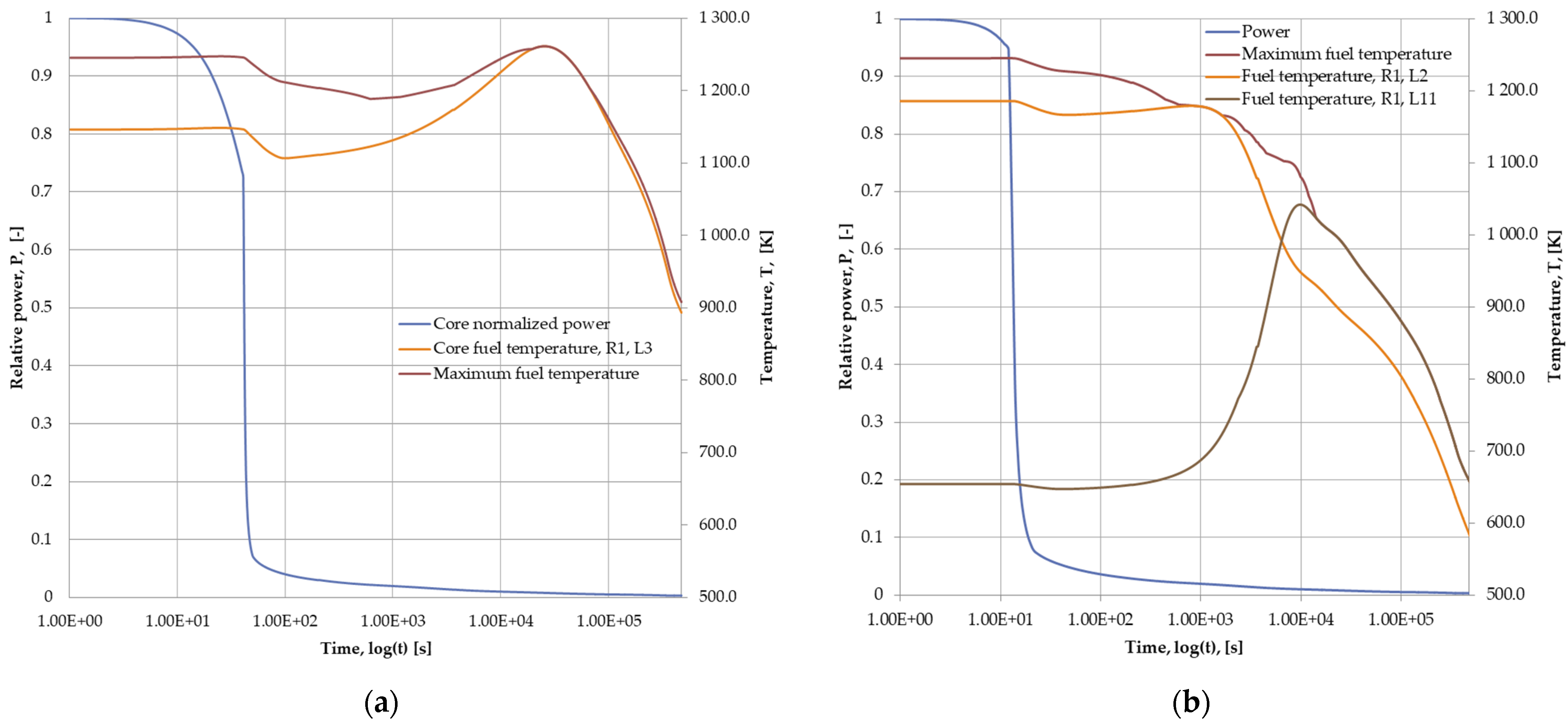
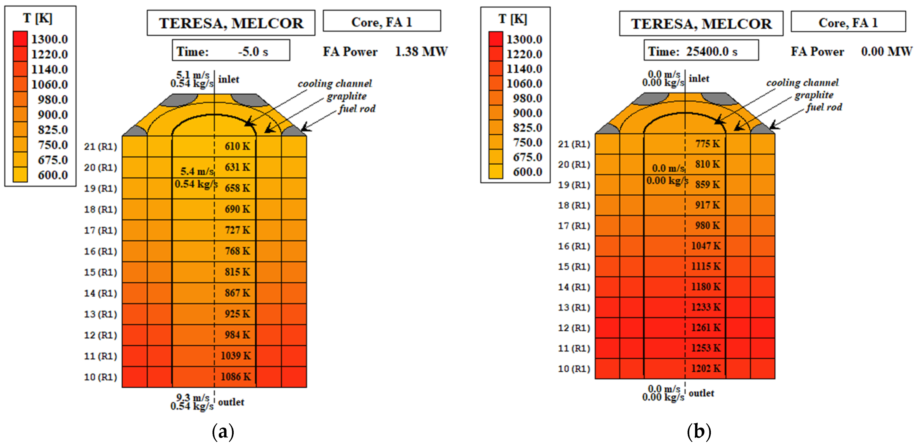
- A Core thermal-hydraulic design able to maintain the fuel temperature below 1600 °C during the most challenging selected DBA event sequences;
- An efficient pre-concept of the decay heat removal system able to perform in various operating conditions.
2. GOSPOSTRATEG-HTR Structure and Objectives
- Development of the novel 40 MWth research HTGR pre-conceptual design.
- Development of the analysis for the radioactive substance distribution in the HTGR circulation loop and radiation hazards under normal operating conditions. Core releases and effects of those hypothetical releases.
- Analysis of built-in safety features, safety systems, requirements for their operation in emergency situations and their classification and qualification for emergency conditions.
- Identification of initiating events and accident scenarios.
- Determination of the distribution and possible propagation processes of fission products in the HTGR reactor and their releases outside the HTGR reactor in situations of DBAs and severe accidents.
- Conclusions regarding the requirements for the barriers in the HTGR reactor as well as the restricted zone and proposals for appropriate changes in legal regulations.
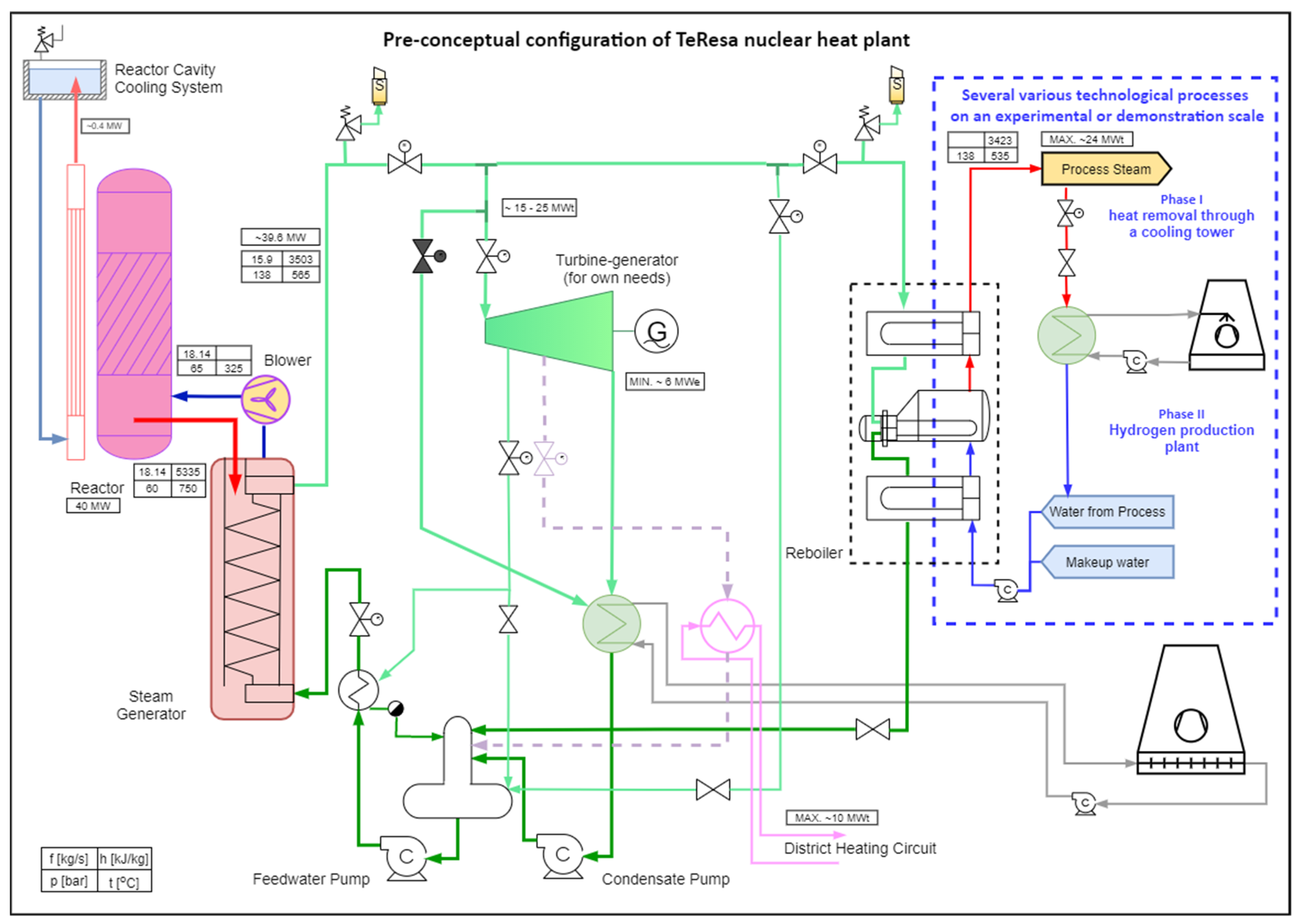
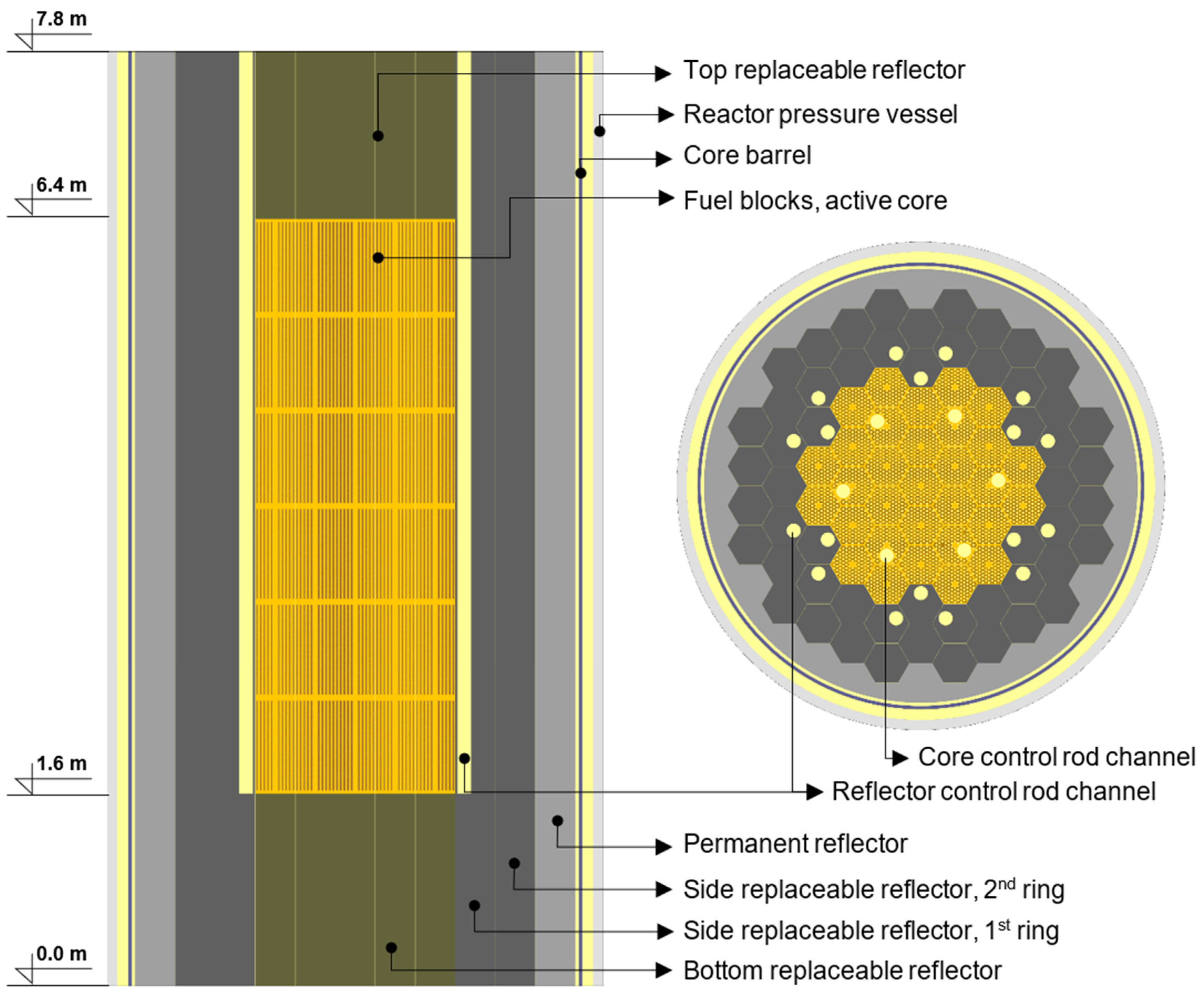
3. TeResa Reactor Design Pre-Concept and Calculations
3.1. Research Reactor Design Philosophy
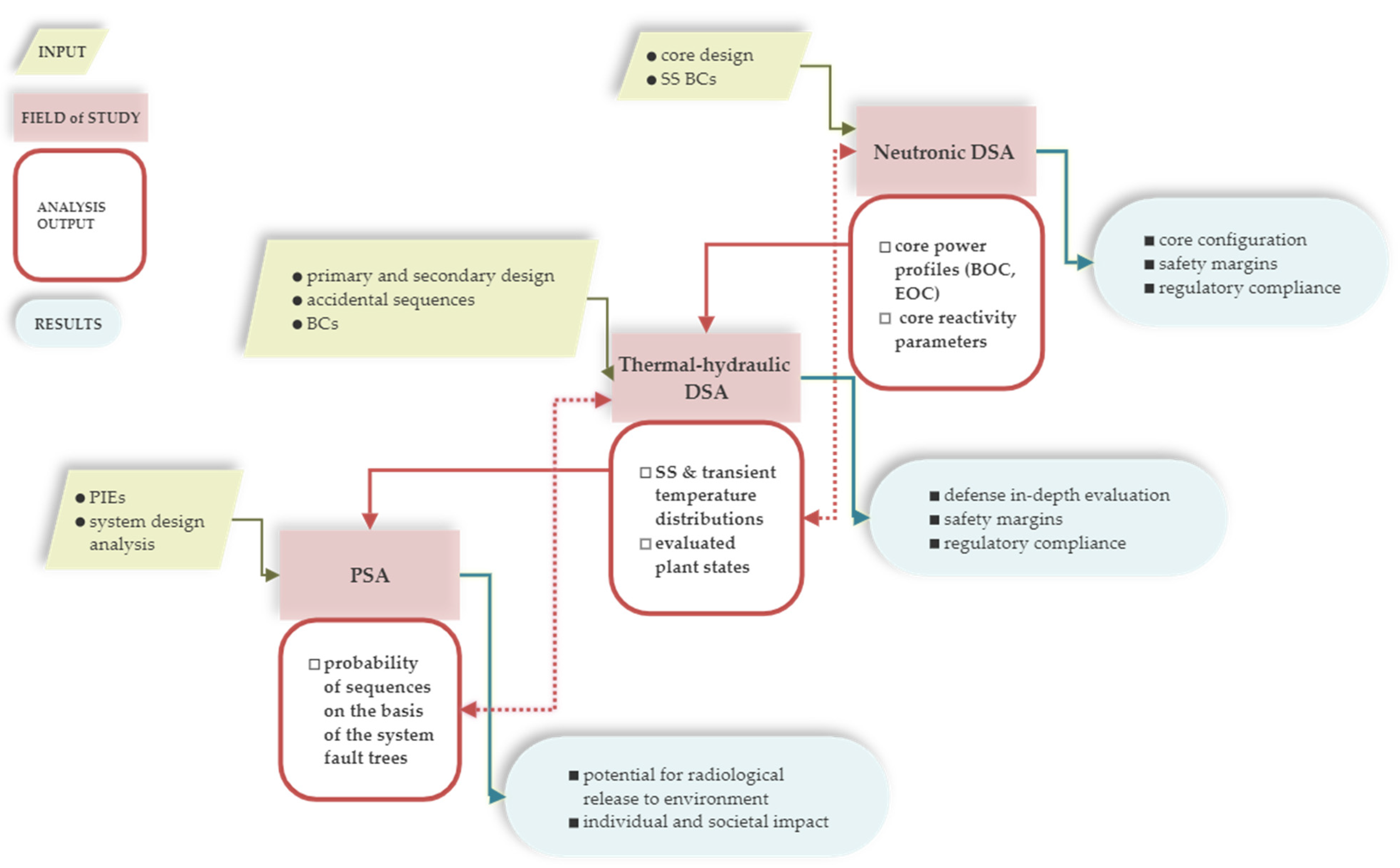
3.2. Current Safety Evaluation Status
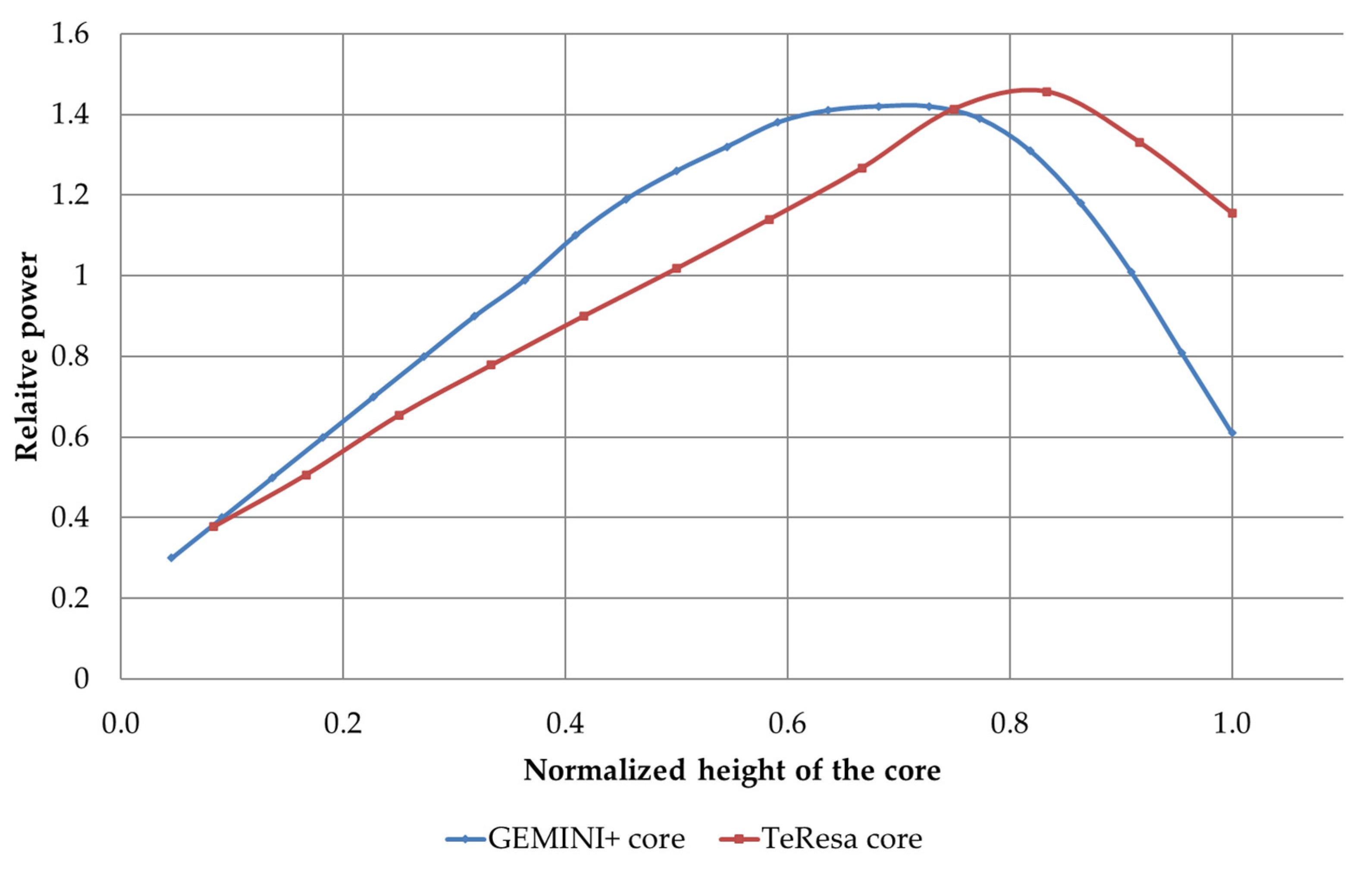
3.3. Exemple Results of TeResa Analysis
4. Final Remarks
Author Contributions
Funding
Institutional Review Board Statement
Informed Consent Statement
Data Availability Statement
Acknowledgments
Conflicts of Interest
References
- The Paris Agreement. Available online: https://unfccc.int/process-and-meetings/the-paris-agreement/the-paris-agreement (accessed on 4 February 2022).
- A European Green Deal. Available online: https://ec.europa.eu/info/strategy/priorities-2019-2024/european-green-deal_en (accessed on 4 February 2022).
- The Glasgow Climate Pact. Available online: https://unfccc.int/process-and-meetings/the-paris-agreement/the-glasgow-climate-pact-key-outcomes-from-cop26 (accessed on 4 February 2022).
- Ministry of Energy. Possibilities for Deployment of High-Temperature Nuclear Reactors in Poland; Ministry of Energy: Warsaw, Poland, 2017.
- Appendix to Resolution No. 8 of the Council of Ministers of 14 February 2017 on the Adoption of the Strategy for Responsible Development for the Period up to 2020 (Including the Perspective up to 2030). Available online: http://isap.sejm.gov.pl/isap.nsf/DocDetails.xsp?id=WMP20170000260 (accessed on 8 February 2022).
- Polish Nuclear Power Programme Adopted by Resolution No. 141 of the Council of Ministers of 2 October 2020. Available online: https://www.infor.pl/akt-prawny/MPO.2020.190.0000946,uchwala-nr-141-rady-ministrow-w-sprawie-aktualizacji-programu-wieloletniego-pod-nazwa-program-polskiej-energetyki-jadrowej.html (accessed on 8 February 2022).
- Ministry of Energy Energy Policy of Poland Till 2040. Available online: http://isap.sejm.gov.pl/isap.nsf/download.xsp/WMP20210000264/O/M20210264.pdf (accessed on 8 February 2022).
- Ministry of Climate and Environment National Energy and Climate Plan for the Years 2021–2030. Available online: https://www.gov.pl/web/klimat/national-energy-and-climate-plan-for-the-years-2021-2030 (accessed on 4 February 2022).
- National Smart Specialisation. Available online: https://smart.gov.pl/en/node/7 (accessed on 4 February 2022).
- Polish Hydrogen Strategy Till 2030. Available online: https://www.gov.pl/web/klimat/polska-strategia-wodorowa-do-roku-2030 (accessed on 4 February 2022).
- Ministry of Science and Higher Education. Polish Roadmap for Research Infrastructures; Ministry of Science and Higher Education: Warsaw, Poland, 2020.
- Action Plan for the Implementation of the Strategic Partnership between the Government of the Republic of Poland and the Government of Japan for the Years 2021–2025. 2021. Available online: https://www.mofa.go.jp/mofaj/files/100186407.pdf (accessed on 7 March 2022).
- GOSPOSTRATEG-HTR Project Website. Available online: http://gohtr.pl/ (accessed on 7 March 2022).
- Lindley, B.; Davies, M.; Hittner, D.; Stempniewicz, M.; de Geus, E.A.R.; Kuijper, J.; Brinkmann, G.; Vanvor, D. Final Description and Justification of GEMINI+ System; European Commission: Brussels, Belgium, 2020. [Google Scholar]
- Act of 29 November 2000—Atomic Law. Available online: http://isap.sejm.gov.pl/isap.nsf/download.xsp/WDU20010030018/O/D20010018.pdf (accessed on 8 February 2022).
- Act of 29 June 2011 on Preparing for and Performing Investments Involving Nuclear Power Facilities and Accompanying Investments. Available online: http://isap.sejm.gov.pl/isap.nsf/DocDetails.xsp?id=WDU20111350789 (accessed on 4 February 2022).
- International Atomic Energy Agency. Applicability of Design Safety Requirements to Small Modular Reactor Technologies Intended for Near Term Deployment; IAEA TECDOC SERIES; IAEA: Wienna, Austria, 2020. [Google Scholar]
- IAEA. Safety Standards, Safety of Nuclear Power Plants: Design; Specific Safety Requirements No. SSR-2/1 (Rev. 1); IAEA: Wienna, Austria, 2016. [Google Scholar]
- Skrzypek, M.; Skrzypek, E.; Stempniewicz, M.; Malesa, J. Study on the DLOFC Accident of the GEMINI+ Conceptual Design of HTGR Reactor with MELCOR and SPECTRA. In Proceedings of the International Conference on High-Temperature Reactor Technology, Online, 2–5 June 2021; IOP Publishing: Bristol, UK, 2021; Volume 2048. [Google Scholar]
- Kuijper, J.C.; Muszynski, D. Neutronics for the GEMINI+ HTGR. J. Phys. Conf. Ser. 2021, 2048, 012030. [Google Scholar] [CrossRef]
- Cetnar, J. Development Studies of the Core Configuration along with the Experimental Program and Numerical Calculations Supporting Safety Analyzes; NCBJ Internal Report; AGH Kraków: Kraków, Poland, 2021. [Google Scholar]
- Malesa, J.; Boettcher, A.; Dąbrowski, M. Cogeneration with HTGR for Industry and District Heating in Poland. In Proceedings of the XV Research and Development in Power Engineering, Warsaw, Poland, 30 November–3 December 2021. [Google Scholar]
- Leppänen, J.; Pusa, M.; Viitanen, T.; Valtavirta, V.; Kaltiaisenaho, T. The Serpent Monte Carlo Code: Status, Development and Applications in 2013. Ann. Nucl. Energy 2015, 82, 142–150. [Google Scholar] [CrossRef]
- Nagaya, Y.; Okumura, K.; Sakurai, T.; Mori, T. MVP/GMVP Version 3 General Purpose Monte Carlo Codes for Neutron and Photon Transport Calculations Based on Continuous Energy and Multigroup Methods; (Translated Document); Japan Atomic Energy Agency: Tōkai, Japan, 2017; 476p. [Google Scholar]
- Cetnar, J.; Gudowski, W.; Wallenius, J. MCB: A Continuous Energy Monte Carlo Burnup Simulation Code. In Actinide and Fission Product Partitioning and Transmutation, EUR 18898 EN, OECD/NEA. 1999; p. 523. Available online: https://oecd-nea.org/trw/docs/mol98/postersession/POSTSpaper12.pdf (accessed on 8 February 2022).
- Humphries, L. MELCOR Computer Code Manuals; Version 2.2.11932; Sandia National Laboratories: Albuquerque, NM, USA, 2018; Volumes 1 & 2. [Google Scholar]
- CATHARE. 2 V25_3mode9.1 Code: General Description; CEA: Paris, France, 2019.
- ANSYS. Ansys Manual Guide, Release 2021 R1; ANSYS: Canonsburg, PA, USA, 2021. [Google Scholar]
- Smith, C.; Knudsen, J.; Vedros, K.; Wood, T. Advanced SAPHIRE 8, Modeling Methods for Probabilistic Risk Assessment via the Systems Analysis, Program for Hands-On Integrated Reliability Evaluations (SAPHIRE) Software P-202; Idaho National Laboratory: Idaho Falls, ID, USA, 2016. [Google Scholar]
- Udiyani, P.M.; Kuntjoro, S. Estimation of Routine Discharge of Radionuclides on Power Reactor Experimental RDE. Urania J. Ilm. Daur Bahan Bakar Nukl. 2017, 23, 48–56. [Google Scholar] [CrossRef][Green Version]
- Verfondern, K.; Sumita, J.; Ueta, S.; Sawa, K. Modeling of Fuel Performance and Metallic Fission Product Release Behavior during HTTR Normal Operating Conditions. Nucl. Eng. Des. 2001, 1–3, 225–238. [Google Scholar] [CrossRef]
- Fütterer, M.A.; D’Agata, E.; Raepsaet, X. Is Tritium an Issue for High Temperature Reactors? Nucl. Eng. Des. 2016, 306, 160–169. [Google Scholar] [CrossRef]
- European Commission, Joint Research Centre. The High Temperature Gas-Cooled Reactor: Safety Considerations of the (V)HTR Modul; Publications Office: Luxembourg, 2017. [Google Scholar]
- Chen, H.; Li, C.; Xing, H.; Fang, C. The R&D of HTR-STAC Program Package: Source Term Analysis Codes for Pebble-Bed High-Temperature Gas-Cooled Reactor. Sci. Technol. Nucl. Install. 2018, 2018, 7389121. [Google Scholar] [CrossRef]
- Owsianko, I. Praca reaktora badawczego MARIA w 2019 roku. Postępy Tech. Jądrowej 2020, 63, 6–11. [Google Scholar]
- Sandia National Laboratories. SCALE/MELCOR Non-LWR SourceTerm Demonstration Project—High-Temperature Gas-Cooled Reactor; Sandia National Laboratories: Albuquerque, NM, USA, 2021. [Google Scholar]
- Petruzzi, A.; D’Auria, F. Thermal-Hydraulic System Codes in Nulcear Reactor Safety and Qualification Procedures. Sci. Technol. Nucl. Install. 2008, 2008, e460795. [Google Scholar] [CrossRef]
- Brinkmann, G.; Vanvor, D.; Jung, A. Final GEMINI + Safety Options Report. European Union’s Horizon 2020 Research and Innovation Programme, 2020. [Google Scholar]
- International Atomic Energy Agency. High Temperature Gas Cooled Reactor Fuels and Materials; IAEA: Vienna, Austria, 2019. [Google Scholar]


| Phase A—Research Phase (1 February 2019–31 July 2020) | ||
|---|---|---|
| WP Number | Work Package Title | Involved Institutions |
| 1 | Development of methods for diagnostics of structural materials in the HTR construction | NCBJ |
| 2 | Development of methods for testing structural materials in a nuclear reactor, and equipment for the execution of tests in the core. | NCBJ |
| 3 | Research and analysis of selected chemical aspects of the production and use of TRISO fuel in the HTR nuclear reactor. | IChTJ |
| 4 | Comprehensive analysis of the necessary changes to the legal environment and the potential benefits of social, economic and industrial units for the Polish economy. | MKiŚ, NCBJ |
| Phase B—Implementation Phase (1 August 2020–31 March 2022) | ||
|---|---|---|
| WP Number | Work Package Title | Involved Institutions |
| 5 | Preparation-licensing process (certification) of HTGRs with the example of a research reactor. | NCBJ, MKiŚ, IChTJ |
| 6 | Preparation draft of legal regulations for the HTR investments implementation and developing a strategy in the social, economic and industrial aspects of the project. | NCBJ, MKiŚ, IChTJ |
| 7 | Piloting test procedures for the use of construction materials for the HTR design, including tests in the MARIA reactor core. | NCBJ |
| 8 | Preparation of technical and economic assumptions for the construction of a fuel production unit for high-temperature reactors. | IChTJ |
| General Information | ||
|---|---|---|
| Unit | Value | |
| Reactor thermal output (gross thermal power) | MWth | 40 |
| HTGR type | - | prismatic, block-type |
| Graphite block type | - | similar to GEMINI+ |
| Graphite block height | cm | 80 |
| Graphite block hexagon flat-to-flat distance | cm | 36 |
| Graphite block material (fuel and reflector blocks) | - | NBG-17 |
| Fuel | - | TRISO, 12% enriched UO2 |
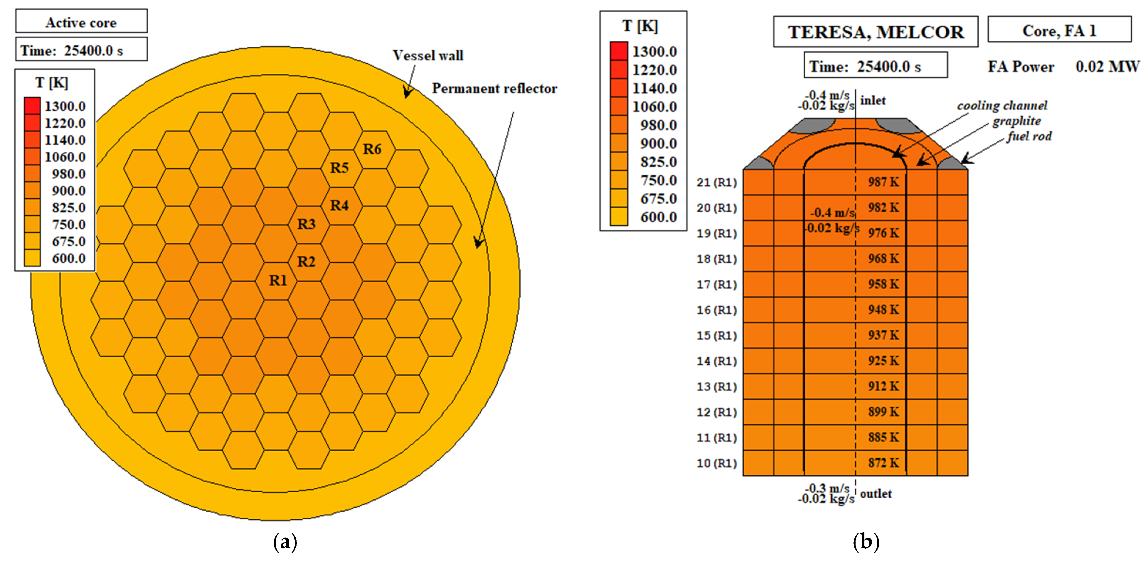
| Active core height | cm | 480 |
| Active core effective diameter | cm | 212 |
| RPV outer radius | cm | 224.4 |
| RPV material | - | SA508 |
| Primary side | ||
| Coolant type | - | helium |
| Coolant flow direction | - | downward flow pattern |
| Helium mass flow rate (at 100% power) | kg/s | 18.14 |
| Primary system pressure | MPa | 6.0 |
| Reactor vessel inlet coolant temperature | °C | 325 |
| Reactor vessel outlet coolant temperature | °C | 750 |
| Number of cooling loops | - | 1 |
| Steam generator type | once-through, helically coiled bundles | |
| Secondary side | ||
| Secondary side coolant | - | water |
| Main steam pressure (at Steam Generator (SG) outlet) | MPa | 13.8 |
| Main steam temperature (at SG outlet) | °C | 540 |
| Main steam mass flow rate (at 100% power) | kg/s | 15.9 |
| Feed water pressure (at SG inlet) | MPa | 13.97 |
| Feed water inlet temperature (at SG inlet) | °C | 210 |
| Feed water mass flow rate (at 100% power) | kg/s | 15.9 |
| CFP Layer | Material | Density [g/cm3] | Outer Radius [μm] |
|---|---|---|---|
| Fuel kernel | uranium dioxide | 10.65 | 250 |
| Buffer layer | porous carbon | 1.05 | 345 |
| Inner PyC layer | pyrolytic carbon | 1.90 | 385 |
| SiC layer | silicon carbide | 3.18 | 420 |
| Outer PyC layer | pyrolytic carbon | 1.90 | 460 |
| Field of Study | Code Name | Outline |
|---|---|---|
| Neutronics | Serpent 2 [23] | Serpent is a continuous-energy multi-purpose three-dimensional Monte Carlo particle transport code. It is in development at VTT Technical Research Centre of Finland since 2004. |
| MVP [24] | MVP (JAEA, Japan) is a general-purpose Monte Carlo code that performs neutron and photon three-dimensional transport calculations using the continuous energy method. | |
| MCB [25] | MCB—Monte Carlo continuous energy burnup code is a general-purpose code used to calculate a nuclide density time evolution, including burnup and decay. Internally, MCB comprises MCNP code, which is used for transport calculations, and is coupled with thermal-hydraulic code POKE (thermohydraulic software)( Gulf General Atomic Incorporated, USA). | |
| Thermal hydraulics | MELCOR 2.2 [26] | MELCOR is a fully integrated, engineering-level computer code developed by Sandia National Laboratories for the U.S. Nuclear Regulatory Commission, that models the progression of severe accidents in nuclear power plants. |
| CATHARE2 [27] | CATHARE (Code for Analysis of Thermal hydraulics during an Accident of Reactor and safety Evaluation) is a two-phase thermal-hydraulic system used in pressurized water reactor safety analyses, the verification post-accidental operating procedures, and in research and development. | |
| ANSYS Fluent 2020 R1 [28] | Ansys FLUENT software contains the broad physical modeling capabilities needed to model flow, turbulence, heat transfer, and reactions for industrial applications. |
| Isotope | Ai,TOT [Bq] | Ai,TeResa,f [Bq/y] |
|---|---|---|
| H-3 | 2.88× 10¹² | 4.09× 10⁸ |
| Kr-83m | 2.46× 10¹⁶ | 5.32× 10¹⁰ |
| Kr-85 | 1.48× 10¹⁵ | 1.27× 10⁶ |
| Kr-85m | 6.12× 10¹⁶ | 1.32× 10¹¹ |
| Kr-87 | 1.12× 10¹⁷ | 2.42× 10¹¹ |
| Kr-88 | 1.50× 10¹⁷ | 3.23× 10¹¹ |
| Xe-131m | 1.86× 10¹⁵ | 4.03× 10⁹ |
| Xe-133 | 3.70× 10¹⁷ | 7.98× 10¹¹ |
| Xe-133m | 1.11× 10¹⁶ | 2.39× 10¹⁰ |
| Xe-135 | 7.73× 10¹⁶ | 1.68× 10¹¹ |
| Xe-135m | 7.47× 10¹⁶ | 1.61× 10¹¹ |
| I-131 | 1.71× 10¹⁷ | 1.47× 10⁸ |
| I-132 | 2.51× 10¹⁷ | 2.17× 10⁸ |
| I-133 | 3.68× 10¹⁷ | 3.17× 10⁸ |
| I-134 | 4.18× 10¹⁷ | 3.63× 10⁸ |
| I-135 | 3.46× 10¹⁷ | 2.99× 10⁸ |
| Rb-88 | 1.51× 10¹⁷ | 3.27× 10⁸ |
| Sr-89 | 2.10× 10¹⁷ | 9.06× 10⁴ |
| Sr-90 | 9.84× 10¹⁵ | 4.25× 10³ |
| Cs-134 | 1.01× 10¹⁶ | 4.36× 10² |
| Cs-137 | 1.17× 10¹⁶ | 5.05× 10² |
| Ag-110m | 1.52× 10¹⁴ | 6.55× 10⁵ |
| Ar-41 | - | 6.57× 10¹² |
| C-14 | - | 1.02× 10⁷ |
| Parameters | Design Value | Simulation MELCOR 2.2 | Relative Error |
|---|---|---|---|
| Reactor power (MWth) | 40 | 40 | 0.000% |
| Helium pressure of primary loop (MPa) | 6 | 6 | 0.000% |
| Helium mass flow rate (kg/s) | 18.14368 | 18.1437 | 0.000% |
| Helium RPV Inlet temperature (K) | 598 | 598 | 0.000% |
| Helium RPV Outlet temperature (K) | 1023 | 1015 | −0.782% |
| Main feed-water temperature (K) | 483 | 482.5 | 0.000% |
| Main steam temperature (K) | 813 | 794 | −3.519% |
| Main steam pressure (MPa) | 13.8 | 13.8 | 0.000% |
| Feed-water flow rate for steam generator (kg/s) | 15.9 | 15.95 | 0.314% |
| Accidental Scenario | Maximum Fuel Temperature | Active Core Axial Position from the Bottom | Active Core Radial Position | Time of Occurrence |
|---|---|---|---|---|
| - | [K] | [m] | [−] | [s] |
| DLOFC | 1261.0 | ~1.0 | central column | 25,400 |
| PLOFC | 1050.0 | ~4.2 | central column | 10,000 |
Publisher’s Note: MDPI stays neutral with regard to jurisdictional claims in published maps and institutional affiliations. |
© 2022 by the authors. Licensee MDPI, Basel, Switzerland. This article is an open access article distributed under the terms and conditions of the Creative Commons Attribution (CC BY) license (https://creativecommons.org/licenses/by/4.0/).
Share and Cite
Skrzypek, E.; Muszyński, D.; Skrzypek, M.; Darnowski, P.; Malesa, J.; Boettcher, A.; Dąbrowski, M.P. Pre-Conceptual Design of the Research High-Temperature Gas-Cooled Reactor TeResa for Non-Electrical Applications. Energies 2022, 15, 2084. https://doi.org/10.3390/en15062084
Skrzypek E, Muszyński D, Skrzypek M, Darnowski P, Malesa J, Boettcher A, Dąbrowski MP. Pre-Conceptual Design of the Research High-Temperature Gas-Cooled Reactor TeResa for Non-Electrical Applications. Energies. 2022; 15(6):2084. https://doi.org/10.3390/en15062084
Chicago/Turabian StyleSkrzypek, Eleonora, Dominik Muszyński, Maciej Skrzypek, Piotr Darnowski, Janusz Malesa, Agnieszka Boettcher, and Mariusz P. Dąbrowski. 2022. "Pre-Conceptual Design of the Research High-Temperature Gas-Cooled Reactor TeResa for Non-Electrical Applications" Energies 15, no. 6: 2084. https://doi.org/10.3390/en15062084
APA StyleSkrzypek, E., Muszyński, D., Skrzypek, M., Darnowski, P., Malesa, J., Boettcher, A., & Dąbrowski, M. P. (2022). Pre-Conceptual Design of the Research High-Temperature Gas-Cooled Reactor TeResa for Non-Electrical Applications. Energies, 15(6), 2084. https://doi.org/10.3390/en15062084