Article

Highly Efficient Solar Laser Pumping Using a Solar Concentrator Combining a Fresnel Lens and Modified Parabolic Mirror

School of Optics and Photonics, Beijing Institute of Technology, No. 5, South Street, Zhongguancun, Beijing 100081, China
*
Author to whom correspondence should be addressed.
Energies 2022, 15(5), 1792; https://doi.org/10.3390/en15051792
Submission received: 5 February 2022 / Revised: 23 February 2022 / Accepted: 25 February 2022 / Published: 28 February 2022
(This article belongs to the Special Issue Challenge and Research Trends of Solar Concentrators)

Abstract

:
Solar-pumped lasers (SPLs) allow direct solar-to-laser power conversion, and hence, provide an opportunity to harness a renewable energy source. Herein, we report significant improvements in end-side-pumped solar laser collection efficiency and beam brightness using a novel 1.5-m-diameter compound solar concentrator combining a Fresnel lens and modified parabolic mirror. A key component of this scheme is the off-axis-focused parabolic mirror. An original dual-parabolic pump cavity is another feature. To determine the dependence of the SPL performance on the distance between the focus and central axis of the modified parabolic mirror, several systems with different distances were optimized using TracePro and ASLD software. It was numerically calculated that end-side pumping a 5-mm-diameter, 22-mm-long Nd:YAG crystal rod would generate 74.6 W of continuous-wave solar laser power at a collection efficiency of 42.2 W/m2, i.e., 1.1 times greater than the previous record value. Considering the laser beam quality, a brightness figure of 0.063 W was obtained, which is higher than that of other multimode SPL designs with end-side pumping. Thus, our SPL concentrator offers the possibility of achieving a beam quality as high as that obtainable via side pumping, alongside highly efficient energy conversion, which is characteristic to end-side pumping.

Graphical Abstract

1. Introduction

Solar energy, as a desirable renewable energy source, has become increasingly important because of the need to reduce fossil fuel consumption and the deterioration of the global environment. Solar-pumped lasers (SPLs) can directly convert light from the sun into laser energy without the requirement for electrically driven artificial pump light sources. The use of these lasers facilitates greater solar energy utilization and has attracted the attention of researchers in the fields of renewable energy and laser technology. Many potential opportunities for SPL use in solar hydrogen generation [1,2,3] and space laser [4,5,6] applications have been predicted.
Because of their applicability, numerous researchers have conducted studies on SPLs. Young reported the first continuous-wave Nd:YAG SPL emission with a power of 1 W in 1966 [7]. To obtain appreciable laser output power, parabolic mirrors with large collection areas, for example, 78.5 m2 [8], 50.2 m2 [9], 38.5 m2 [10], and 6.75 m2 [11], were used to concentrate solar radiation on laser media in early studies. These primary concentrators with parabolic mirrors were very large and expensive, and the mechanical supporting structures of the laser cavities inside the parabolic mirrors produced shadows that reduced the effective solar energy collection area. In the last decade, the adoption of Fresnel lens designs has accelerated the development of low-cost solar lasers with reduced weight. As a consequence, many studies focusing on obtaining higher laser collection efficiency, which is defined as the laser output power per unit area of the solar collector, have been conducted in recent years. In 2007, Yabe et al. obtained an 18.7 W/m2 laser collection efficiency by end pumping a 9-mm-diameter, 100-mm-long Cr:Nd:YAG ceramic rod using a 1.3-m2 Fresnel lens [12]. In 2011, a laser collection efficiency of 19.3 W/m2 was achieved by Liang and Almeida using a 0.64-m2 Fresnel lens to end-side pump a 4-mm-diameter, 25-mm-long Nd:YAG crystal rod [13]. In 2012, Dinh et al. reported a 30-W/m2 laser collection efficiency when end-side pumping a 6-mm-diameter, 100-mm-long Nd:YAG crystal using a 4-m2 Fresnel lens [14]. More recently, in 2018, Guan et al. achieved a 32.1-W/m2 laser collection efficiency with the use of a 1.03-m2 Fresnel lens for end-side pumping a 6-mm-diameter, 95-mm-long Nd:YAG–YAG-bonded crystal rod [15]. However, because of the defects of Fresnel lenses such as dispersion, which limits the geometric concentration ratio, Fresnel lenses have not completely replaced parabolic mirrors in SPL designs. For example, in 2018, Liang et al. reported a laser collection efficiency of 32.5 W/m2 when end pumping a 4.5-mm-diameter, 35-mm-long Cr:Nd:YAG ceramic rod using a heliostat-parabolic mirror with a 1.0-m2 effective collection area, which represents the record for highest solar laser collection efficiency [16]. In addition, sunlight is more focused when concentrated by parabolic mirrors rather than Fresnel lenses, because of the absence of dispersion. Thus, compared with SPLs with Fresnel lenses, SPLs with parabolic mirrors typically have a better brightness figure of merit [17,18], which is defined as the ratio between laser power and the product of the Mx2 and My2 factors [11]. The use of a parabolic mirror in an SPL design also makes it compatible with side pumping to produce a TEM00-mode output [19,20].
Either a Fresnel lens or a parabolic mirror is used as the primary concentrator in almost all SPLs. However, as mentioned above, a drawback of the former is dispersion, whereas when the latter is used, the laser cavity shadows the incoming solar light. Hence, neither option is the perfect choice for the primary concentrator of a SPL. Therefore, it is very important to develop new solar-energy collection and concentration systems. In recent years, many novel solar concentrators have been proposed, and numerically calculated laser performances for their use in SPLs have been reported [21,22,23,24,25]. Among these, a modified ring-array concentrator (RAC) allowed some remarkable laser performances to be achieved. When a small Fresnel lens was added to the center of the RAC, laser collection efficiencies of 38.4 and 29.18 W/m2 were obtained via end-side pumping and side pumping a Nd:YAG crystal, respectively [22,25].
A novel 1.5-m-diameter solar concentrator composed of a modified parabolic mirror and Fresnel lens mounted coaxially is proposed in this paper. To avoid shadowing in the laser cavity, a section of the parabolic mirror behind the focal point is removed. Thus, the total solar collection area, including the remaining annular parabolic mirror section and the Fresnel lens, spans 1.766 m2. As a compound structure, this solar concentrator combines the advantages of Fresnel lenses and parabolic mirrors. When compared with a parabolic mirror concentrator, the replaced part with a Fresnel lens produces a solar concentrator that is less heavy and shadowing does not occur. When compared with a typical Fresnel lens concentrator, the reduced diameter of the Fresnel lens in this compound system means that the influence of dispersion is reduced. Further, because the Fresnel lens and parabolic mirror pump the laser medium from the end and side, respectively, flexible adjustment of the solar power distribution in the laser medium is possible. It should also be mentioned that because the focus of the modified parabolic mirror is off-axis, serious heat accumulation in the laser medium is prevented.
A series of optimizations performed using the TracePro and ASLD simulation software packages ensured that, when combined with a novel dual-parabolic pump cavity, the solar radiation collected by this solar concentrator was uniformly and efficiently absorbed by a 5-mm-diameter, 22-mm-long Nd:YAG single-crystal laser rod. The continuous-wave solar laser output power was 74.6 W, and laser beam quality factors of Mx2 = 34.0 and My2 = 35.1 were obtained numerically; the corresponding laser collection efficiency was 42.2 W/m2, and the beam brightness figure of merit was 0.063 W, i.e., 1.1 and 2.6 times greater than the previous records, respectively, for an end-side pumped SPL [22]. The structure model, design principles, and optimization of the detailed parameters are explained in Section 2. The laser performance, numerically calculated by ASLD software, is explained in Section 3. A discussion of the results is presented in Section 4.

2. Method

The solar laser output power (Pout) can be analytically calculated in terms of absorbed solar power (Pab) and other quantities by Equation (1) [26],
P out = 1 R 1 + R A I S [ 2 η Q η S η B P a b ( 2 α l + L M ln R ) A I S 1 ]
which is considered as the overall theoretical design method. Here, R is the output coupler reflectivity, A is the cross-sectional area of the laser rod, IS is the saturation intensity, and ηQ, ηS, and ηB are the quantum efficiency, Stokes’ factor, and beam overlap efficiency, respectively. The factor 2αl accounts for the two-way absorption and scattering loss of the laser medium inside the laser resonator, that is, α is the scattering and absorption coefficient of the laser material, and LM represents other losses in the resonator. It is evident that the solar laser output power (Pout) has a positive correlation with the absorbed solar power (Pab), and a negative correlation with the length (l) of the laser medium. In addition, the thermal effects caused by inhomogeneous solar absorption distributions also affect the solar laser output power. Hence, this approach is aimed to achieve a homogeneous distribution and efficient solar radiation absorption in the laser rod with a shorter length.
The model of the SPL proposed in this paper (Figure 1) is composed of two major parts, the solar energy collection and concentration system and the solar laser head. The structure of these two parts and their optical principles are explained in Section 2.1 and Section 2.2, respectively. On this basis, more detailed parameters in this approach are optimized in TracePro to obtain an efficient solar radiation absorption, and this process is presented step by step in Section 2.3.

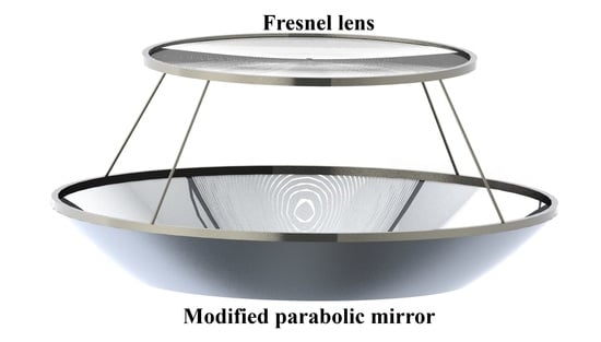
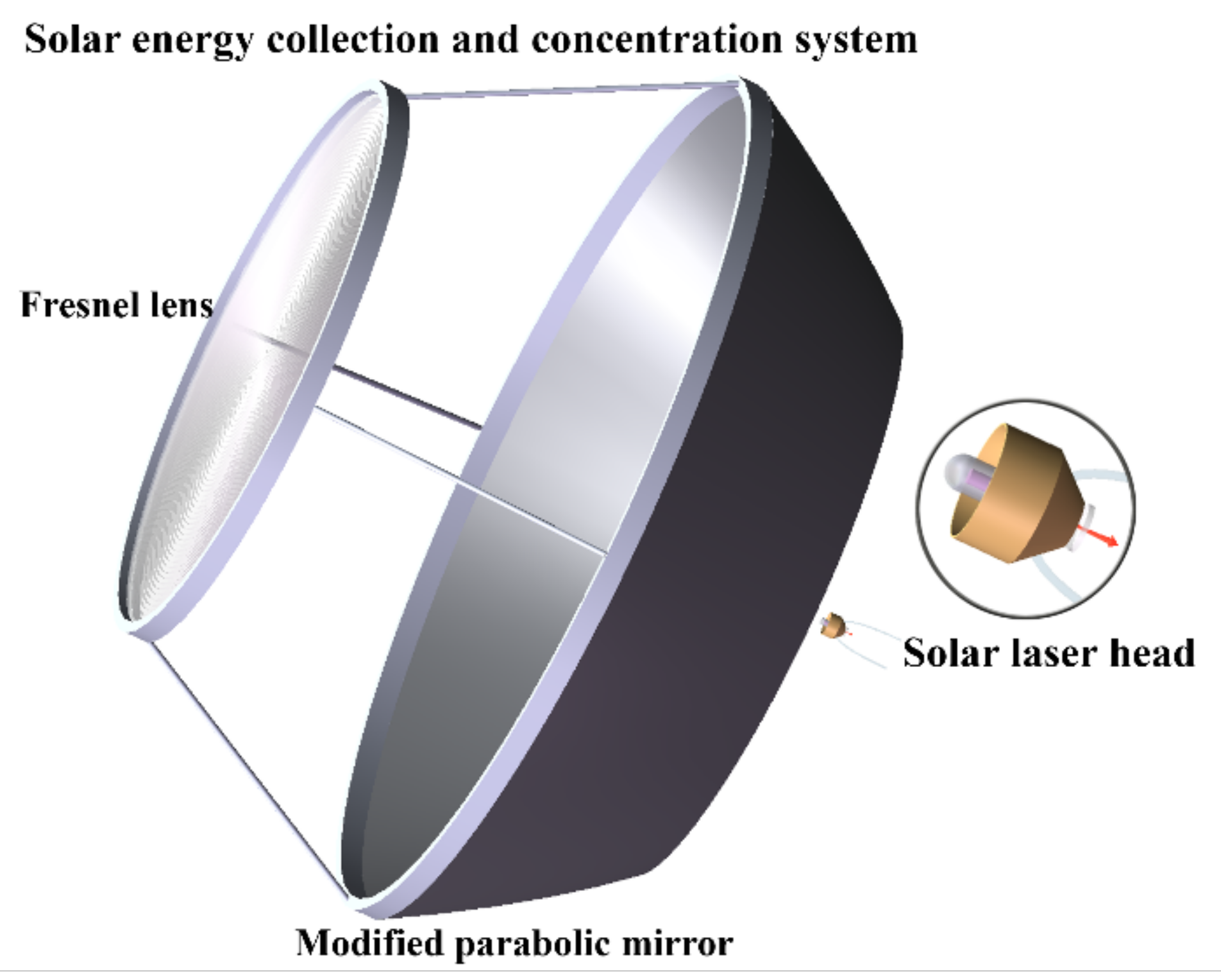
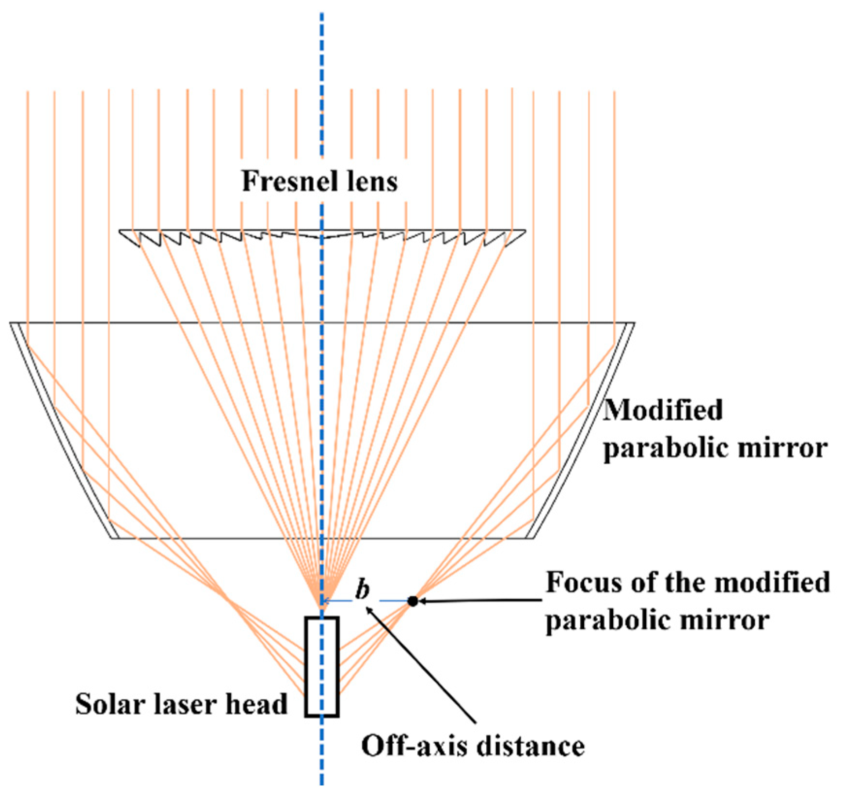
2.1. Solar Energy Collection and Concentrator System

The structure of the primary concentrator proposed in this paper (Figure 2) consists of a Fresnel lens and a modified parabolic mirror with an aperture of 1.5 m. The Fresnel lens was placed at the top of the concentrator system to concentrate the sunlight at the front end of the laser head; the diameter and focal length were both 1 m. The parabolic mirror was mounted coaxially below the Fresnel lens to concentrate sunlight onto the sides of the laser head; its parabolic surface was silver-coated (reflectivity R = 95% for sunlight). The inner and outer diameters of the modified parabolic mirror were 1.5 and 1 m, respectively, and the other parameters were numerically optimized using TracePro optical simulations based on geometric optics analysis.
The schematic diagrams in Figure 3 show a conventional parabolic mirror (Figure 3a) for comparison alongside the proposed modified parabolic mirror, for which the focus is off-axis (Figure 3b,c). In general, the reflective surface of a parabolic mirror takes the form of a parabola with the equation x2 = 2py in the XOY plane that is rotated around the Y axis (Figure 3a), and this structure concentrates light at the focal point (p/2,0). However, when the collection area of the parabolic mirror is large and most of the optical power is highly concentrated at the focal position, serious heat accumulation in the laser medium can occur. Therefore, we moved the parabola horizontally outward and inward, varying the distance b between the focus and central axis (Figure 3b,c). This design means that along the central axis, the light is slightly unfocused, being longitudinally stretched; thus, the average solar power in the concentrated area is reduced, rendering it suitable for side pumping the laser medium.
Laser media end pumped by sunlight from primary concentrators in SPLs always have inhomogeneous solar absorption distributions, with strong absorption at the top that is gradually reduced along the axial direction of the laser media [15,16,18]. The Fresnel lens in the primary concentrator is expected to produce this type of distribution in the laser medium. When sunlight is incident parallel to the central axis on the parabolic mirror, the mirror surface near the upper edge reflects the sunlight at a smaller convergence angle. Therefore, when the parabola is moved inward (Figure 3b), an absorber on the central axis sits in front of the focus, and its solar absorption distribution weakens gradually from top to bottom along the axial direction (Figure 4a). Conversely, when the parabola is moved outward (Figure 3c), the focus is in front of the absorber, and the opposite distribution occurs (Figure 4b); in this case, a laser medium on the central axis absorbs little power at the top, but this gradually increases along the axial direction toward the bottom. Thus, the parabolic mirror should be moved outward to concentrate sunlight on the side of the laser medium and produce a solar absorption distribution opposite to that of the Fresnel lens. Owing to the complementarity of the Fresnel lens and modified parabolic mirror, the compound primary concentrator can generate a uniform solar absorption distribution in the laser medium, and the reduction in heat accumulation in the laser medium means that a laser output with better beam quality factors can be expected.
The focal length p/2 and distance between the focus and central axis b, which affects the incident angle and position of the solar light concentrated on the laser head, were optimized using TracePro. After outward deviation from the central axis, the curve equation of the parabolic mirror is (xb)2 = 2py and the focus occurs at (b, p/2), on the right side of the XOY plane (Figure 3c). To avoid shadowing, p/2 should take an appropriate value such that the laser cavity can be placed behind the focal point. At the lower boundary of the parabolic mirror, the focal length should satisfy the condition (500 − b)2/2pp/2, i.e., p ≤ 500 − b. When the value of p is close to the maximum value, the longitudinal length of the parabolic mirror is small; thus, the weight of the system is reduced. Moreover, in this case, the incident angles of the sunlight concentrated by the parabolic mirror on the laser medium will be smaller, which will reduce the transmission loss of pump light on the surface of the laser medium.

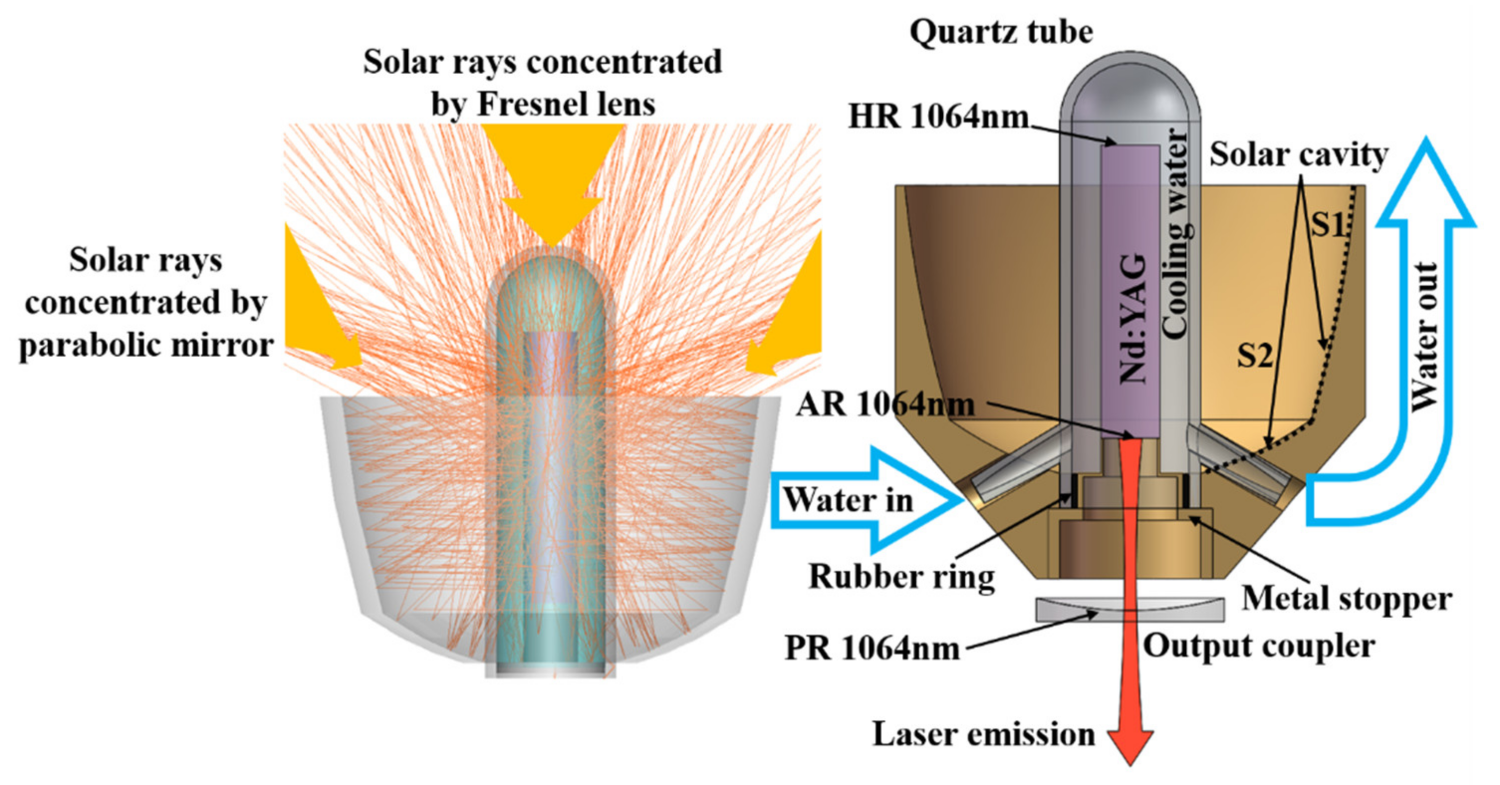
2.2. Solar Laser Head

The solar laser head of this system was composed of a dual-parabolic-surface pump cavity and a liquid light guide lens (LLGL) (Figure 5), within which was mounted a 5-mm-diameter Nd:YAG single-crystal laser rod with a high-reflection (HR) coating optimized for 1064 nm on the front face and an antireflection (AR) coating for the same wavelength on the back face. The output coupler behind the laser rod was coated for partial reflection (PR) at 1064 nm, and the laser resonator was bounded by a PR output coupler and HR-coated mirror.
The inner wall of the pump cavity was silver-coated to achieve 95% sunlight reflectivity. Homogeneous distribution and efficient solar radiation absorption in the laser rod were generated owing to the fact that the inner wall of the pump cavity consisted of two parabolic surfaces S1 and S2 (Figure 5). Sunlight that had been concentrated by the parabolic mirror but transmitted through the laser medium without being fully absorbed was mostly incident on the side surface of the pump cavity. The parabolic surface S1 had the form of a left-opening parabola with the curve equation in the XOY plane (yp/2)2 = −2m(x − (m/2 − b)) that is rotated around the Y axis (Figure 6). Because S1 was focused at the same point as the parabolic mirror of the primary concentrator, from the opposite direction, sunlight beams concentrated by the parabolic mirror (red lines in Figure 6) passing through the laser rod, were reflected in parallel by the paraboloid mn (yellow lines in Figure 6), and then passed through the laser rod for a second time; these beams were finally reflected by the paraboloid m’n’ on the other side of the central axis (green lines in Figure 6), and were incident on the laser rod for a third time. This parabolic cavity provides an isosceles triangle pathway for sunlight, which allows a short length of laser rod to fully absorb the incident sunlight. Solar light that had been concentrated by the Fresnel lens and passed through the laser medium without being fully absorbed was mostly incident on the end surface of the pump cavity, which took the form of an upward-opening parabolic surface (S2). All the parameters of S1 and S2 were optimized using TracePro.
The LLGL consisted of a quartz tube filled with water for cooling. When filled with water, the head and side of the LLGL act as spherical and cylindrical lenses, respectively, enlarging the effective absorption areas of the end and side surfaces of the laser media. The water was pumped by an external water pump to cool the laser medium. The inner wall of the quartz tube had a diameter of 10 mm, and the space around the laser rod was deemed sufficient for efficient water cooling of both the laser medium and the LLGL. The bottom opening of the quartz tube was blocked by an internal hollow metal stopper, which was connected to the end of the laser rod by a 5-mm-diameter hollow cylinder. The diameter of the inner hole was approximately 5 mm, and hence the laser resonator was hardly affected. The metal structure was partially silver-coated inside the quartz tube (R = 95% for sunlight), which allowed the laser rod length to be reduced such that the rod was shorter than the quartz tube and filled the void of the pump cavity, reflecting some of the sunlight back into the pump cavity.

2.3. Optimization of the Optical Design Parameters Using TracePro

To achieve the maximum absorbed solar pump power with the shortest laser rod length, the design parameters of the primary concentrator and laser head were optimized using the optical simulation software TracePro. For this system, several parameters were preset in TracePro, according to the actual experimental conditions. The Fresnel lens material was polymethyl methacrylate (PMMA), its diameter and focal length were both 1 m, the ring distance was 0.33 mm, and its thickness was 3 mm. The inner and outer diameters of the parabolic mirror section were 1.5 and 1 m, respectively, and the surface reflectivity was assumed to be 95%. The material of the quartz tube of the LLGL was fused silica, and the inner and outer diameters were set to 10 and 12 mm, respectively. A 5-mm-diameter Nd:YAG single-crystal laser rod was mounted coaxially in the quartz tube 8-mm away from the top of the spherical surface, and its initial length was set to 40 mm. A total of 50,000 rays distributed over a half-angle of ±0.27° were set within the 1.5-m aperture range to simulate incident sunlight, and the standard solar spectrum (air mass, AM1.5) was used in the calculations to distribute 980 W/m2 of solar irradiance over the wavelengths of the solar spectrum (ASTM G173-03 International standard) in TracePro [27]. The absorption and dispersion spectra of all the materials were also defined, and the absorption spectrum of the Nd: YAG crystal was set assuming a Nd3+ doping concentration of 1%. Subsequently, the absorbed solar power was obtained by calculating the absorption and loss in the laser rod. Four steps for optimization of the modified parabolic mirror, parabolic surface S1 in the pump cavity, laser rod length, and parabolic surface S2 in the pump cavity were sequentially considered. According to the absorbed solar energy from the flux table generated by TracePro, these steps are outlined as follows.

2.3.1. Step 1: Optimization of the Modified Parabolic Mirror

When the offset distance b between the focus and the central axis is large, a large length of laser rod is needed to absorb a sufficient amount of sunlight, and when b is small, the sunlight is too concentrated and may damage the laser rod. Through a comparative analysis, it was determined that the optimal value of b was in the range of 20–50 mm. Therefore, four typical values for the offset distances, 20, 30, 40, and 50 mm, were used in the subsequent analysis; for comparison, a conventional parabolic mirror was also simulated. To distinguish the concentrator systems, they were labeled systems 1–5 according to the value of b.
Based on the analysis in Section 2.1, when the value of b is in the range of 20–50 mm, the focal length p/2 of the paraboloid has a maximum value of 225 mm for ideal parallel light incidence. However, because of the solar divergence angle of 0.27°, the focal length should be smaller, and after gradually reducing the value of p/2 in TracePro, it was found that a value of 200 mm was appropriate. The parameters of these parabolic mirrors and the solar power absorbed by the laser rods for the different systems (1–5) are shown in Table 1.

2.3.2. Step 2: Optimization of Parabolic Surface S1 in the Pump Cavity

Ray tracing and visual analysis using TracePro allowed the positions and diameters of the input windows of the pump cavities to be rapidly determined. The surface equations of S1 can also be calculated using the expression defined in Section 2.2, (yp/2)2 = −2m(x − (m/2 − b)). As shown in Figure 7, there are clear boundaries defining the ranges over which the parabolic surface S1 receives sunlight, and this data can be used as the basis for determining the depth of S1 in the pump cavity. The position and diameter of the input windows of the pump cavities, the parameters of the parabolic surfaces S1, and the absorbed solar power in the laser rods when this structure is used with each of the different concentrators are listed in Table 2.

2.3.3. Step 3: Optimization of the Laser Rod Length

As shown in Figure 8, when the length of the laser rod is 40 mm, parts of the rod absorb little solar power. Table 3 shows the laser rod length optimization results. Although the absorbed solar power in the laser rods decreased slightly as the laser rod length was increased, the absorption and scattering losses in the resonator were greatly reduced, which would result in increased solar-to-laser power conversion efficiencies.

2.3.4. Step 4: Optimization of Parabolic Surface S2 in the Pump Cavity

The upper edge of parabolic surface S2 was bonded with the lower edge of parabolic surface S1, and the output diameter of the pump cavity was the same as that of the diameter of the quartz tube. The surface equation for S2 was completely determined by the value of the focal length n/2. As the focal length must be selected to ensure that the focus of S2 is within the laser rod, all the possible values of n were used to determine the maximum absorbed solar power in the laser rod; the results are summarized in Table 4.
The influences of the different parameter optimization steps on the absorbed solar power per unit length of laser rod are summarized in Figure 9. It is apparent that design optimization using TracePro means that these systems are able to efficiently concentrate high-power solar radiation into short lengths of the Nd: YAG laser rod. Thermal effects in the resonator laser and output parameters were further analyzed using the ASLD laser simulation software package, as outlined in Section 3.

3. Result

To perform laser output power and beam quality analyses, simulated laser resonators were set up in ASLD [28]. In the ASLD simulation, the laser resonator was bounded by a concave mirror with a PR coating and a face with an HR coating (R > 99.9%) at the right and left ends of the laser rod, respectively; the other end face of the laser rod was AR-coated (R < 0.1%) to reduce cavity losses. The length of the laser resonator was 200 mm, and the other losses in the resonator, which occurred mainly at the end faces of the laser rod, were assumed to total to 0.003 cm−1. The “pumping description” in ASLD was imported from the “absorbed–lost flux data matrix” file of the TracePro simulation, which migrated all the solar ray absorption and loss information from the optimized laser medium in TracePro to laser resonators in ASLD. The parameters of the laser medium in ASLD were also consistent with those of TracePro. Moreover, “temperature boundary conditions” of the laser medium were set as cooling with water. In the ASLD analysis, a doping density of 1.39 × 10¹⁷ ions/mm3, fluorescence lifetime of 2.3 × 10⁻⁴ s, stimulated emission cross-section of 2.8 × 10⁻¹⁹ cm2, quantum efficiency of 0.95 [26], and laser medium scattering and absorption coefficient of 3 × 10⁻³ cm−1 for the Nd:YAG medium containing 1.0 at.% Nd3+ were used as inputs. A wavelength of 660 nm was used as the mean intensity-weighted absorbed solar pump wavelength [9]. By dividing the laser medium into 169,377 discretization grids and running a finite element analysis (FEA), both thermal conditions and the laser performance could be calculated in ASLD.
Owing to the narrow range of the solar spectrum that can be utilized by the SPL [29], solar power usually contributes to severe heating of the laser medium in SPLs. Therefore, the thermal conditions of the laser rods were analyzed. Figure 10 shows the temperature and thermally induced stress distributions in the laser rods pumped by these concentrator systems, which were evaluated by FEA in ASLD. As the distance between the focus of the parabolic mirror and the central axis b increased, the thermal stress in the laser rod was significantly suppressed, and the maximum temperatures in the rods decreased, from 439.6 K (b = 0) to 389.2 K (b = 20 mm), 366.7 K (b = 30 mm), 354.9 K (b = 40 mm), and 353.8 K (b = 50 mm). Regarding stress, the maximum values of 118, 86.45, 70.56, and 68.37 N/mm2, obtained for the systems with b in the range of 20–50 mm, were far below the stress fracture limit for the Nd:YAG medium of 200 N/mm2 [26], whereas the value for the b = 0 system was 189.4 N/mm2, i.e., close to the fracture limit.
The output beam-quality performance of the laser rods is summarized in Table 5. Using the dual-parabolic-surface pump cavity, solar radiation was coupled into the short laser rods efficiently and uniformly, and high-efficiency conversion from solar power to laser power was realized. The optimized SPL based on the concentrator system with a parabolic mirror having a focal length of 200 mm and offset distance of 30 mm was shown to have the best laser output performance, with an output laser power of 74.6 W and beam quality factors of Mx2 = 34.0 and My2 = 35.1. From this result, a laser collection efficiency of 42.2 W/m2 and a beam brightness figure of merit of 0.063 W were calculated.

4. Discussion

In this study, a novel compound solar concentrator was proposed and applied to the design of a solar-pumped laser. Significant improvements in not only the solar laser collection efficiency but also the laser beam quality was numerically calculated using this structure combined with a novel dual-parabolic-surface pump cavity. Five systems distinguished by different distances between the focus and central axis of the modified parabolic mirror were modeled in TracePro, and the solar concentrator and pump cavity designs for each of these systems were optimized using TracePro and ASLD numerical analyses. Consequently, it was numerically predicted that by end-side pumping a 5-mm-diameter, 22-mm-long Nd:YAG crystal rod, 74.6 W of continuous-wave laser power with beam quality factors of Mx2 = 34.0 and My2 = 35.1 could be obtained, corresponding to a collection efficiency of 42.2 W/m2 and a beam brightness figure of merit of 0.063 W, which were 1.1 times and 2.6 times greater, respectively, than the current record values.
A comparison between the results obtained in this study and the previous records, for both end-side-pumping [22] and side-pumping [25] schemes, is presented in Table 6. Although the laser rod was end-side pumped in this work, the beam quality was nearly as high as that previously obtained via side-pumping, and the highly efficient energy conversion characteristic of end-side pumping was retained.
In this study, the most popular solid-state laser medium, Nd:YAG, was used. However, the optical structures developed are applicable for pumping other rod-shaped solar laser media. In particular, it would be interesting to investigate the use of the compound solar collector and dual-parabolic pump cavity with other laser media that absorb more strongly in the solar emission spectrum but suffer from more serious thermal effects, such as Cr:Nd:YAG ceramics, Nd:Ce:YAG, or alexandrite single crystals. The observed characteristics of the developed optical setup, i.e., homogenized pump-light absorption and the suppression of thermal effects, suggest that an SPL design incorporating these more absorbing media with the new optical elements might achieve better performance, i.e., higher laser collection efficiency or better beam quality.
In addition, the structure proposed in this paper was not complex, with only three parts coaxially mounted and, as far as we know, all the specific mechanisms and optical surfaces could be processed. Therefore, the proposed approach could be used for SPLs, which we shall investigate in future.

Author Contributions

Conceptualization, Z.C. and C.Z.; Data curation, Z.C.; formal analysis, Z.C. and Z.Z. (Ziyin Zhao); funding acquisition, C.Z.; investigation, Z.C.; methodology, Z.C. and C.Z.; project administration, C.Z.; resources, C.Z., H.Z. and Z.Z. (Zilong Zhang); software, Z.C. and Z.Z. (Ziyin Zhao); supervision, C.Z., H.Z. and Z.Z. (Zilong Zhang); validation, Z.C., Z.Z. (Ziyin Zhao) and X.Y.; visualization, Z.C.; writing—original draft, Z.C.; writing—review & editing, Z.C., C.Z., H.Z. and Z.Z. (Zilong Zhang). All authors have read and agreed to the published version of the manuscript.

Funding

This research was funded by the National Natural Science Foundation of China, grant number 61378020 and 61775018.

Data Availability Statement

Not applicable.

Conflicts of Interest

The authors declare no conflict of interest. The funders had no role in the design of the study; in the collection, analyses, or interpretation of data; in the writing of the manuscript, or in the decision to publish the results.

References

  1. Yabe, T.; Uchida, S.; Ikuta, K.; Yoshida, K.; Baasandash, C.; Mohamed, M.S.; Sakurai, Y.; Ogata, Y.; Tuji, M.; Mori, Y.; et al. Demonstrated fossil-fuel-free energy cycle using magnesium and laser. Appl. Phys. Lett. 2006, 89, 261107. [Google Scholar] [CrossRef]
  2. Ohkubo, T.; Yabe, T.; Yoshida, K.; Uchida, S.; Funatsu, T.; Bagheri, B.; Oishi, T.; Daito, K.; Ishioka, M.; Nakayama, Y.; et al. Solar-pumped 80 W laser irradiated by a Fresnel lens. Opt. Lett. 2009, 34, 175–177. [Google Scholar] [CrossRef]
  3. Yabe, T.; Bagheri, B.; Ohkubo, T.; Uchida, S.; Yoshida, K.; Funatsu, T.; Oishi, T.; Daito, K.; Ishioka, M.; Yasunaga, N.; et al. 100 W-class solar pumped laser for sustainable magnesium-hydrogen energy cycle. J. Appl. Phys. 2008, 104, 083104. [Google Scholar] [CrossRef]
  4. Mori, M.; Kagawa, H.; Saito, Y. Summary of studies on space solar power systems of Japan Aerospace Exploration Agency (JAXA). Acta Astronaut. 2006, 59, 132–138. [Google Scholar] [CrossRef]
  5. Guan, Z.; Zhao, C.M.; Yang, S.H.; Wang, Y.; Ke, J.Y.; Zhang, H.Y. Demonstration of a free-space optical communication system using a solar-pumped laser as signal transmitter. Laser Phys. Lett. 2017, 14, 055804. [Google Scholar] [CrossRef]
  6. Takeda, Y.; Iizuka, H.; Mizuno, S.; Hasegawa, K.; Ichikawa, T.; Ito, H.; Kajino, T.; Ichiki, A.; Motohiro, T. Silicon photovoltaic cells coupled with solar-pumped fiber lasers emitting at 1064 nm. J. Appl. Phys. 2014, 116, 014501. [Google Scholar] [CrossRef]
  7. Young, C.G. A Sun-Pumped cw One-Watt Laser. Appl. Opt. 1966, 5, 993–997. [Google Scholar] [CrossRef]
  8. Arashi, H.; Oka, Y.; Sasahara, N.; Kaimai, A.; Ishigame, M. A Solar-Pumped cw 18 W Nd:YAG Laser. Jpn. J. Appl. Phys. 1984, 23, 1051–1053. [Google Scholar] [CrossRef]
  9. Weksler, M.; Shwartz, J. Solar-pumped solid-state lasers. IEEE J. Quantum Electron. 1988, 24, 1222–1228. [Google Scholar] [CrossRef]
  10. Benmair, R.M.J.; Kagan, J.; Kalisky, Y.; Noter, Y.; Oron, M.; Shimony, Y.; Yogev, A. Solar-pumped Er, Tm, Ho:YAG laser. Opt. Lett. 1990, 15, 36–38. [Google Scholar] [CrossRef]
  11. Lando, M.; Kagan, J.; Linyekin, B.; Dobrusin, V. A solar-pumped Nd:YAG laser in the high collection efficiency regime. Opt. Commun. 2003, 222, 371–381. [Google Scholar] [CrossRef]
  12. Yabe, T.; Ohkubo, T.; Uchida, S.; Yoshida, M.; Nakatsuka, M.; Funatsu, T.; Mabuti, A.; Oyama, A.; Nakagawa, K.; Oishi, T.; et al. High-efficiency and economical solar-energy-pumped laser with Fresnel lens and chromium codoped laser medium. Appl. Phys. Lett. 2007, 90, 261120. [Google Scholar] [CrossRef]
  13. Liang, D.; Almeida, J. Highly efficient solar-pumped Nd:YAG laser. Opt. Express 2011, 19, 26399–26405. [Google Scholar] [CrossRef] [PubMed]
  14. Dinh, T.H.; Ohkubo, T.; Yabe, T.; Kuboyama, H. 120 watt continuous wave solar-pumped laser with a liquid light-guide lens and an Nd:YAG rod. Opt. Lett. 2012, 37, 2670–2672. [Google Scholar] [CrossRef] [PubMed]
  15. Guan, Z.; Zhao, C.; Li, J.; He, D.; Zhang, H. 32.1 W/m2 continuous wave solar-pumped laser with a bonding Nd:YAG/YAG rod and a Fresnel lens. Opt. Laser Technol. 2018, 107, 158–161. [Google Scholar] [CrossRef]
  16. Liang, D.; Vistas, C.R.; Tibúrcio, B.D.; Almeida, J. Solar-pumped Cr:Nd:YAG ceramic laser with 6.7% slope efficiency. Sol. Energy Mater. Sol. Cells 2018, 185, 75–79. [Google Scholar] [CrossRef]
  17. Vistas, C.R.; Liang, D.; Almeida, J.; Tibúrcio, B.D.; Garcia, D.; Catela, M.; Costa, H.; Guillot, E. Ce:Nd:YAG side-pumped solar laser. J. Photonics Energy 2021, 11, 018001. [Google Scholar] [CrossRef]
  18. Tibúrcio, B.; Liang, D.; Almeida, J.; Garcia, D.; Vistas, C.R.; Morais, P. Highly efficient side-pumped solar laser with enhanced tracking-error compensation capacity. Opt. Commun. 2020, 460, 125156. [Google Scholar] [CrossRef]
  19. Liang, D.; Almeida, J.; Vistas, C.R.; Guillot, E. Solar-pumped TEM00 mode Nd:YAG laser by a heliostat—Parabolic mirror system. Sol. Energy Mater. Sol. Cells 2015, 134, 305–308. [Google Scholar] [CrossRef]
  20. Mehellou, S.; Liang, D.; Almeida, J.; Bouadjemine, R.; Vistas, C.R.; Guillot, E.; Rehouma, F. Stable solar-pumped TEM00-mode 1064 nm laser emission by a monolithic fused silica twisted light guide. Sol. Energy 2017, 155, 1059–1071. [Google Scholar] [CrossRef]
  21. Xiong, S.; He, Y.; Liu, X. Parabolic ring array concentrator for solar-pumped laser. J. Appl. Opt. 2014, 35, 531–536. [Google Scholar]
  22. Matos, R.; Liang, D.; Almeida, J.; Tibúrcio, B.D.; Vistas, C.R. High-efficiency solar laser pumping by a modified ring-array concentrator. Opt. Commun. 2018, 420, 6–13. [Google Scholar] [CrossRef]
  23. Boutaka, R.; Liang, D.; Bouadjemine, R.; Traiche, M.; Kellou, A. A Compact Solar Laser Side-Pumping Scheme Using Four Off-Axis Parabolic Mirrors. J. Russ. Laser Res. 2021, 42, 453–461. [Google Scholar] [CrossRef]
  24. Catela, M.; Liang, D.; Vistas, C.R.; Garcia, D.; Tibúrcio, B.D.; Costa, H.; Almeida, J. Doughnut-Shaped and Top Hat Solar Laser Beams Numerical Analysis. Energies 2021, 14, 7102. [Google Scholar] [CrossRef]
  25. Tibúrcio, B.D.; Liang, D.; Almeida, J.; Matos, R.; Vistas, C.R. Improving solar-pumped laser efficiency by a ring-array concentrator. J. Photonics Energy 2018, 8, 018002. [Google Scholar] [CrossRef]
  26. Koechner, W. Solid-State Laser Engineering, 6th ed.; Springer: New York, NY, USA, 2006. [Google Scholar]
  27. ASTM G173-03(2012). Standard Tables for Reference Solar Spectral Irradiances: Direct Normal and Hemispherical on 37° Tilted Surface; ASTM: West Conshohocken, PA, USA, 2012. [Google Scholar]
  28. Advanced Software for Laser Design (ASLD). Multiphysics Laser Simulation Software. Available online: http://www.asldweb.com/index.html (accessed on 4 February 2022).
  29. Zhao, B.; Zhao, C.; He, J.; Yang, S. The Study of Active Medium for Solar-Pumped Solid-State Lasers. Acta Opt. Sin. 2007, 27, 1797–1801. [Google Scholar]
Figure 1. Model of the solar-pumped laser consisting of the solar energy collection and concentration system and the solar laser head.
Energies 15 01792 g001
Figure 2. Schematic of the primary concentrator consisting of a Fresnel lens and modified parabolic mirror.
Energies 15 01792 g002
Figure 3. Parabolic mirror schematics: (a) Principle of conventional parabolic mirror; (b) Parabolic mirror with inwardly deviated focus; (c) Parabolic mirror with outwardly deviated focus.
Energies 15 01792 g003
Figure 4. Solar absorption distributions of absorbers along the axial direction: (a) A absorber in front of the focus; (b) A absorber behind the focus.
Energies 15 01792 g004
Figure 5. Liquid light-guide lens (LLGL) and dual-parabolic pump cavity containing 5-mm-diameter Nd:YAG rod. The incident solar light, 1064-nm laser resonator, water cooling scheme, and locations of the two parabolic surfaces in the solar cavity are illustrated.
Energies 15 01792 g005
Figure 6. Schematic of the parabolic surface S1 showing the isosceles-triangle pathway for sunlight using different colors. Red, yellow, and green lines represent the solar rays before reflection in the cavity, after the first reflection, and after the second reflection, respectively.
Energies 15 01792 g006
Figure 7. Distributions of incident solar light intensity on the surface of the pump cavity S1 for different systems: (a) System 1; (b) System 2; (c) System 3; (d) System 4; (e) System 5.
Energies 15 01792 g007
Figure 8. Incident solar power distributions along the axial direction of laser rods for the different systems (red area indicates the higher incident light intensity and the purple areas indicate lower incident light intensity.): (a) System 1; (b) System 2; (c) System 3; (d) System 4; (e) System 5. The optimized length of rod l is shown in each panel.
Energies 15 01792 g008
Figure 9. Influence of the optimization processes on the absorbed solar power per unit length laser of rod.
Energies 15 01792 g009
Figure 10. Numerically calculated temperature and stress distributions in Nd:YAG rods in the different optimized solar-pumped laser systems: (a) System 1; (b) System 2; (c) System 3; (d) System 4; (e) System 5.
Energies 15 01792 g010
Table 1. Parameters of the modified parabolic mirror and absorbed solar power concentrated by the different primary concentrator systems and LLGL without considering the pump cavity.
System No.12345
Focal length p/2 (mm)200200200200200
Deviation distance b (mm)020304050
Distance above the laser head (mm)109.589786858
Absorbed solar power (W)177.2157.1157.2157.2157.2
Table 2. Parameters of the parabolic surface S1 and absorbed solar power for each system investigated.
System No.12345
Distance behind the laser head (mm)4.556710
Diameter of input window (mm)21.835.539.451.256.6
Focal length of the S1 parabola m/2 (mm)1138506679
Depth (mm)715182630
Absorbed solar power (W)241.2229.8226.0222.2219.7
Table 3. Lengths and reductions in the absorbed solar power and resonator losses (compared with a 40-mm-long Nd:YAG rod) for the laser rods of the different systems investigated.
System No.12345
Laser rod length (mm)918222427
Absorbed solar power (W)187.2202.5202.5200.9199.0
Reduction in resonator losses (%)77.555454032.5
Reduction in absorbed solar power (%)22.411.910.49.69.4
Table 4. Parameters of the parabolic surface S2 and absorbed solar power for the different systems investigated.
System No.12345
Focal length of S2 parabola n/2 (mm)616223242
Absorbed solar power (W)210.6228.7232.3230.7233.3
Table 5. Output laser performance parameters for different optimized SPL systems.
System No.12345
Output mirror reflectivity0.950.940.930.930.93
Laser output power (W)70.273.574.668.471.5
Laser collection efficiency (W/m2)39.841.642.238.740.5
Mx251.835.734.037.136.3
My253.336.935.139.237.1
Conversion efficiency (%)4.064.254.313.954.13
Table 6. Comparisons between results obtained in this work and previous record results for end-side pumping [22] and side pumping [25].
ParametersRef. [22]Ref. [25]Present WorkFold Change with Respect to
Ref. [22]Ref. [25]
Collection area (m2)1.761.711.76--
Pumping configurationend-side-pumpingside-pumpingend-side-pumping--
Laser output (W)67.849.8974.6--
Collection efficiency (W/m2)38.429.1842.21.11.45
Conversion efficiency (%)4.03.074.311.081.40
Average M2 factor M x 2 +   M y 2 2 55.033.034.6--
Figure of merit (W)0.0240.0460.0632.6251.370
Publisher’s Note: MDPI stays neutral with regard to jurisdictional claims in published maps and institutional affiliations.

