
Formulations, Solving Algorithms, Existing Problems and Future Challenges of Pre-Programmed PWM Techniques for High-Power AFE Converters: A Comprehensive Review


Abstract
1. Introduction
- Working at low switching frequency, which is beneficial to reduce switching losses and improve the reliability and efficiency of the high-power AFE converter;
- Allowing overmodulation, which can achieve high voltage gain as it causes an increased utilization of the DC bus;
- Reducing or even removing additional filtering components/systems, and it can further reduce total cost of power systems;
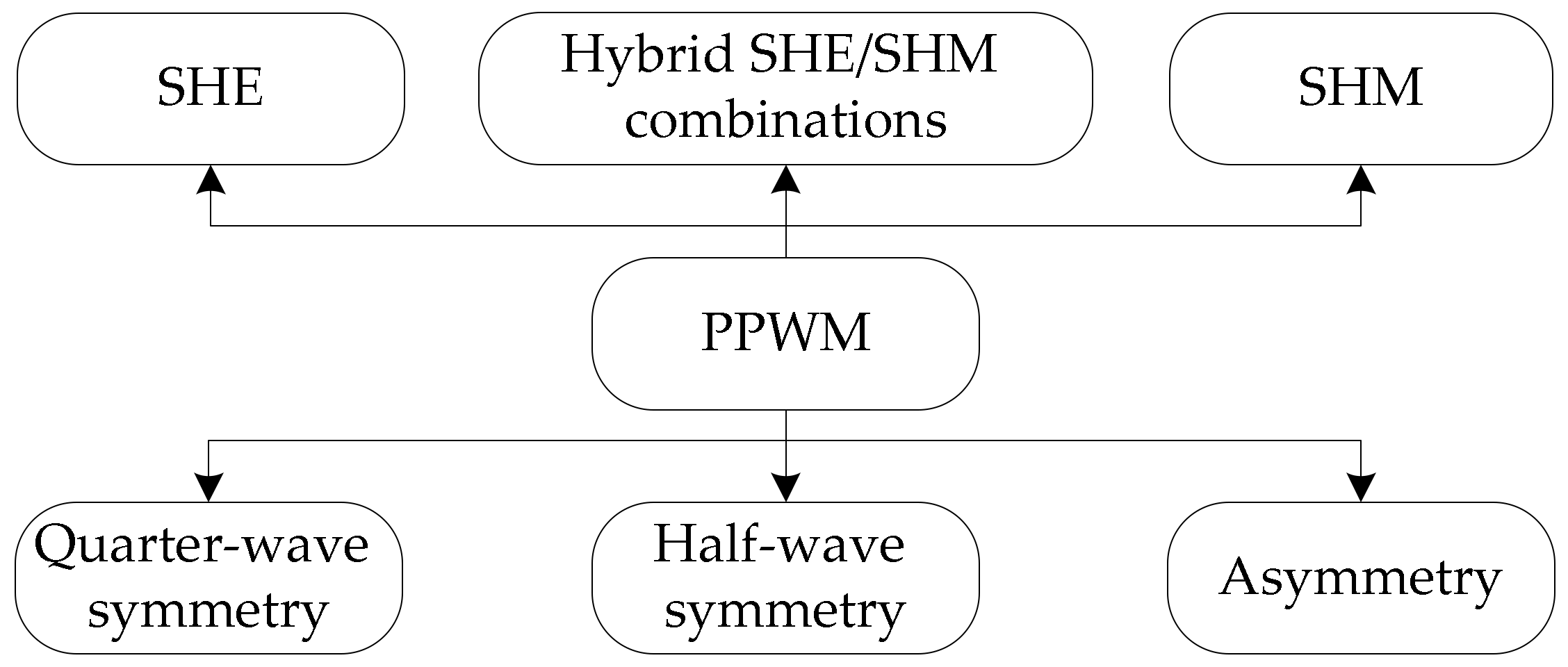
- For SHE, the specific low-order harmonics can be strictly eliminated while keeping the fundamental harmonic at a pre-determined value, which can avoid harmonic interference and resonance phenomena;
- For SHM, its idea is to keep the harmonic content below the limits imposed by the particular applied grid codes, while also considering the resulting voltage/current total harmonic distortion (THD) from the perspective of power quality.
- For hybrid SHE/SHM combinations, their performance indices can be optimized based on a given power quality aspect to a certain degree.
2. PPWM Formulations
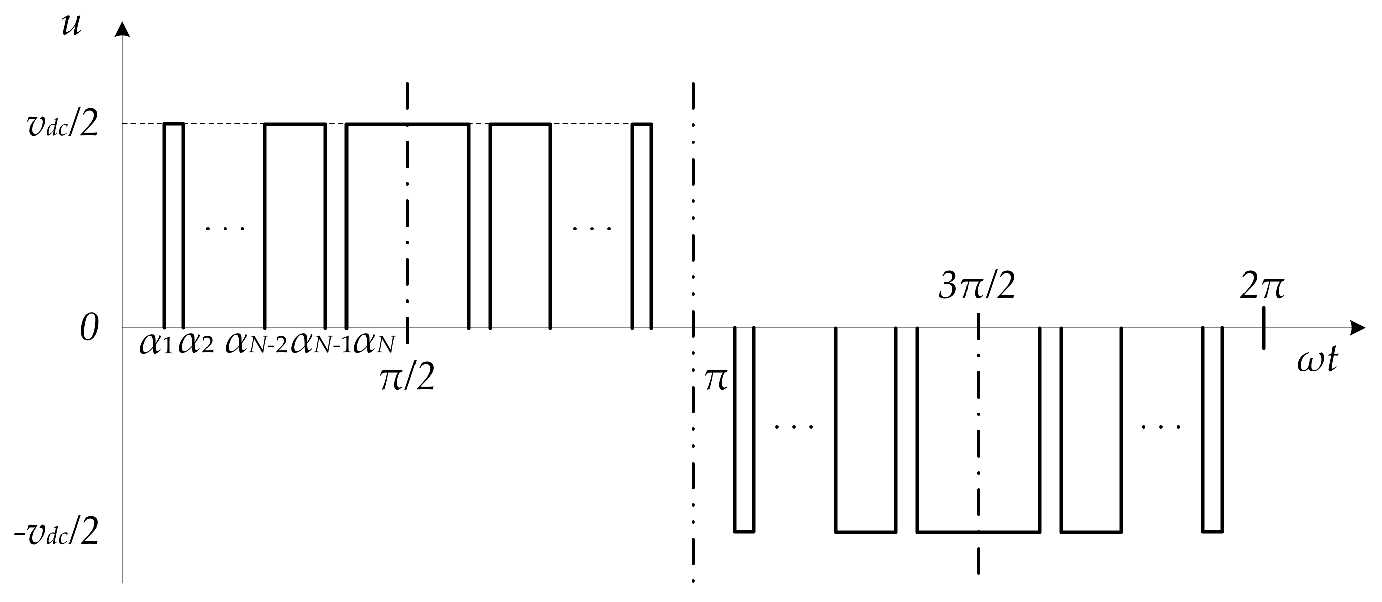
2.1. PPWM Formulation with Quarter-Wave Symmetry
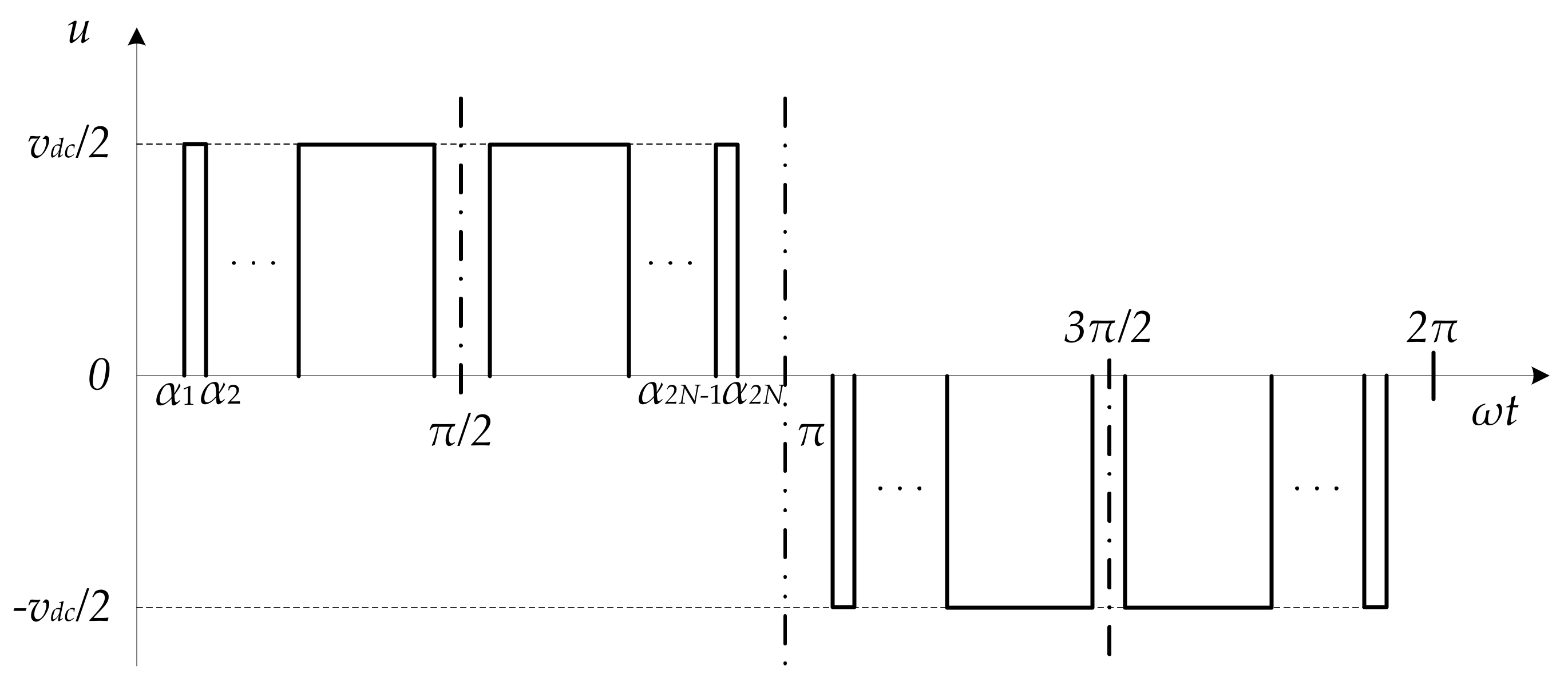
2.2. PPWM Formulation with Half-Wave Symmetry
2.3. PPWM Formulation with Asymmetry
3. Solving Algorithms for PPWM Techniques
3.1. Numerical Methods
- The iteration efficiency of algorithm;
- The determination of initial values for algorithm.
3.2. Algebraic Methods
3.3. Intelligent Optimization Methods
- They have lower requirement or are less dependent on the determination of initial values for PPWM formulations than numerical methods. This demand exists as high-power AFE converters are used in more and more applications and the methods with the need of initial values are not competent for this case;
- They are easy and clear for understanding and implementation due to the great development of the artificial intelligence techniques in the past few decades.
3.4. Other Improved Methods for Real-Time/Online Implementation
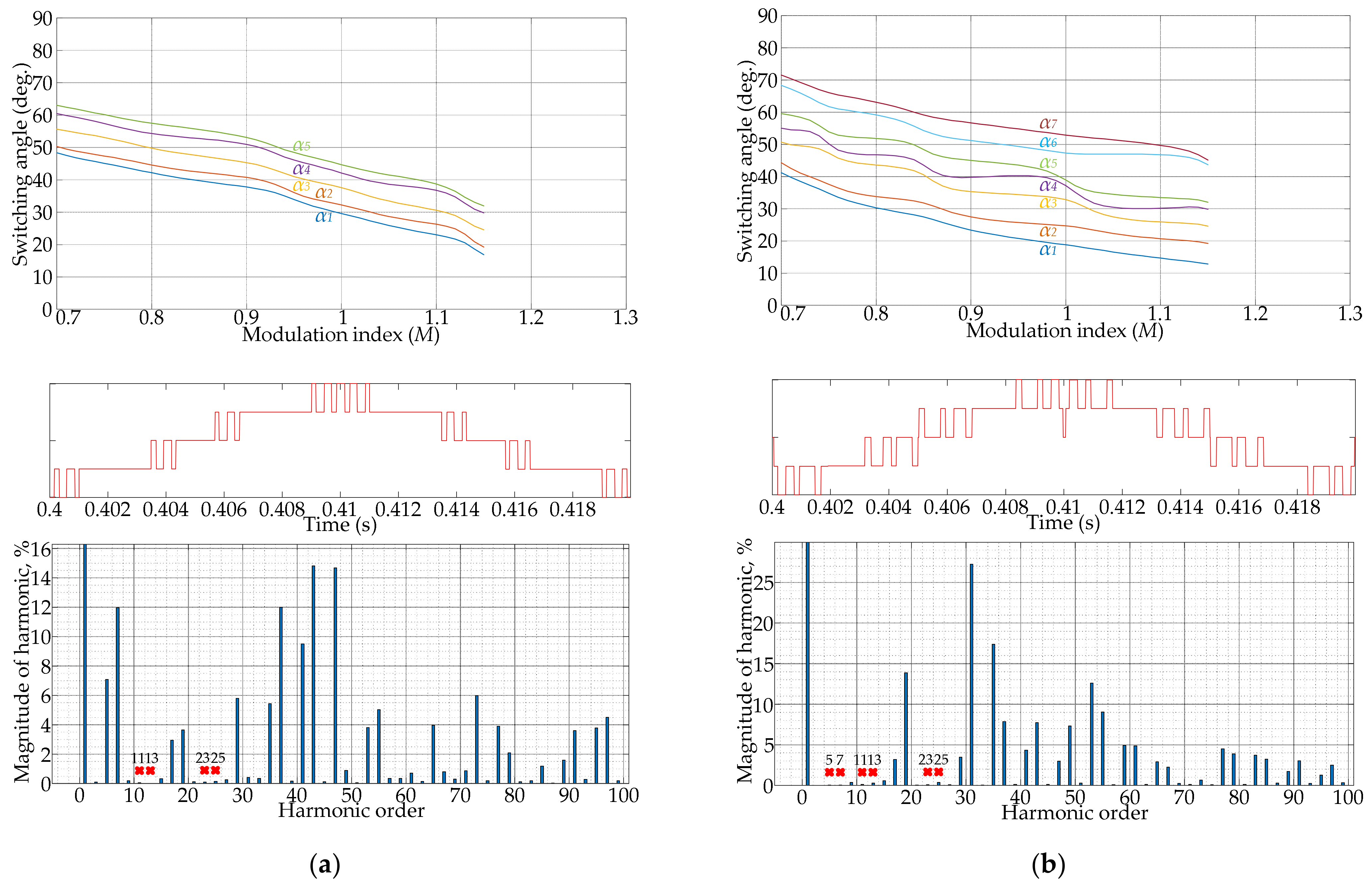
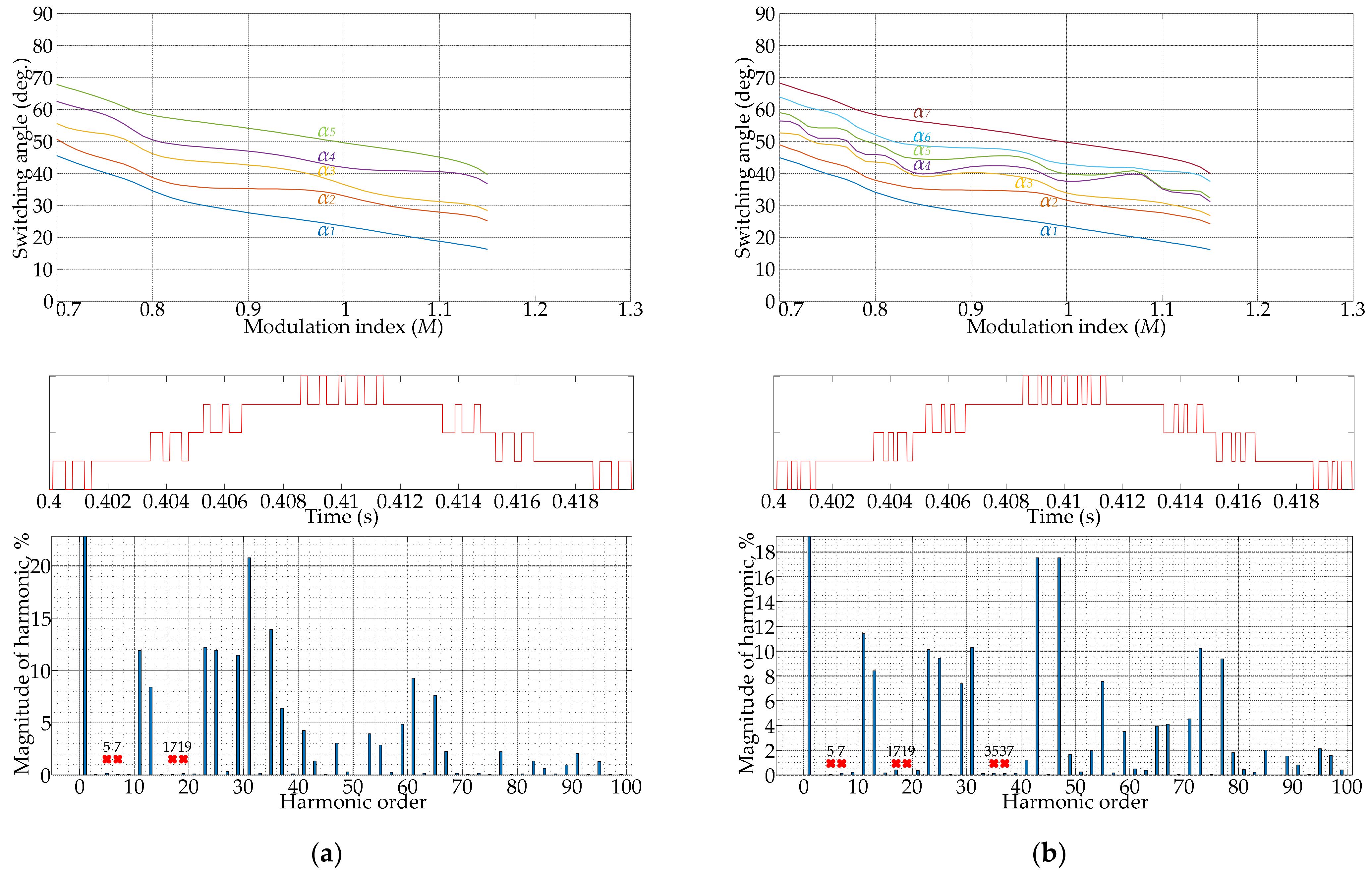
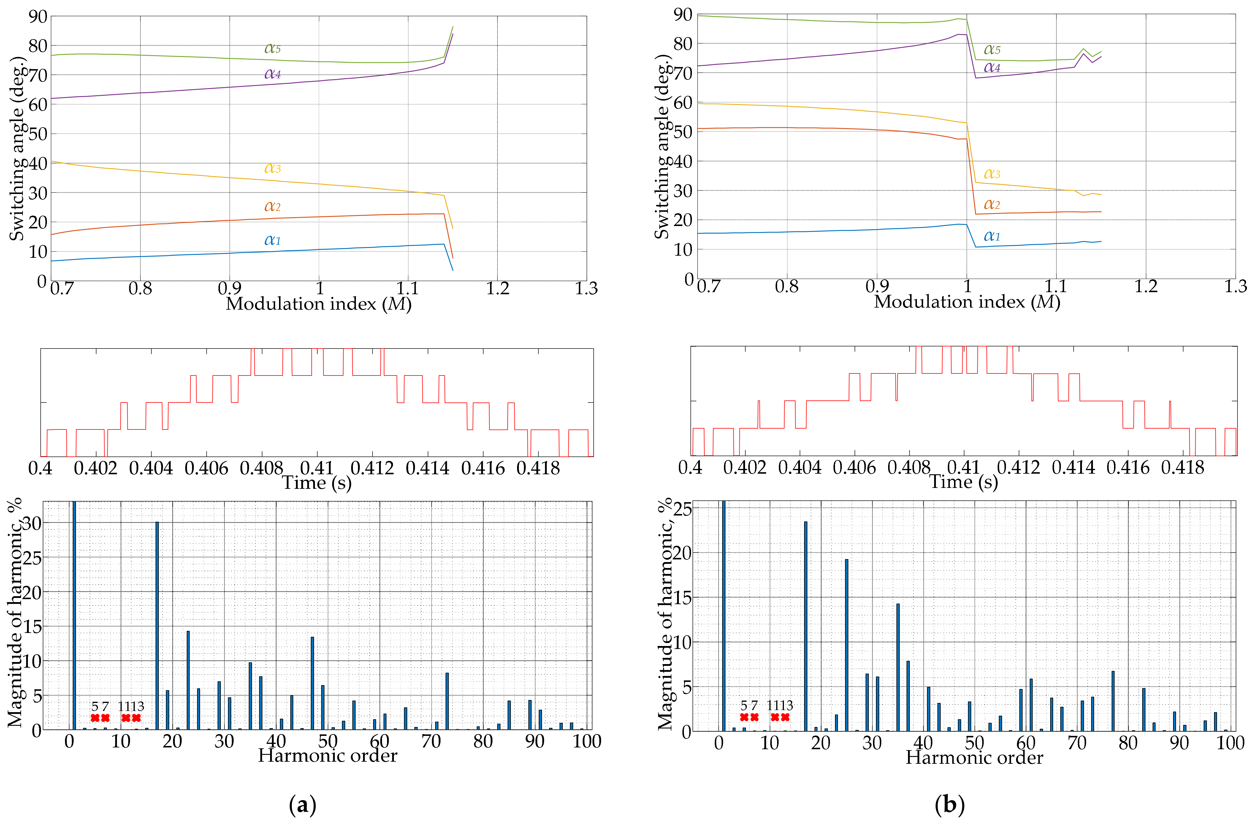
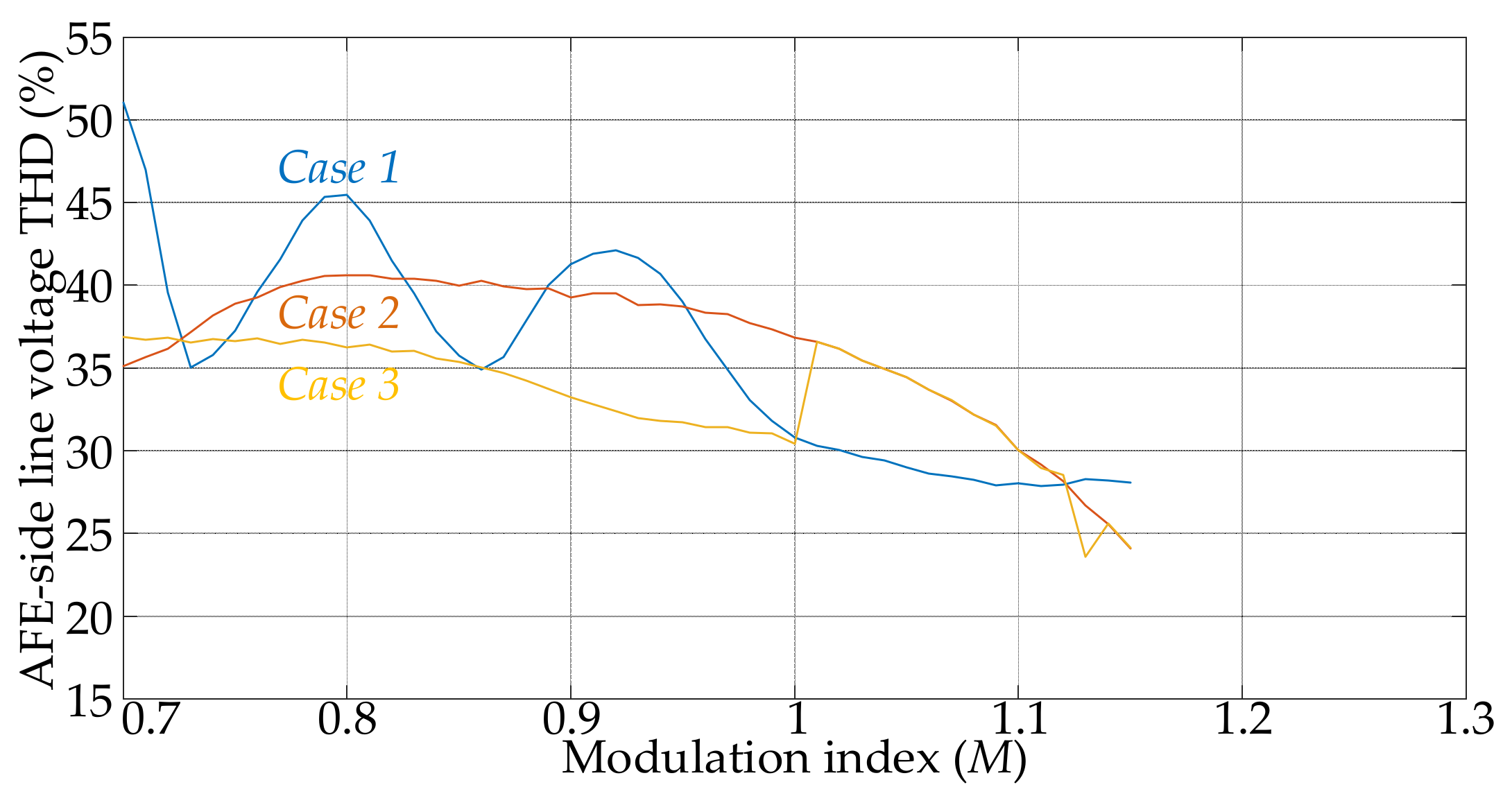
4. Illustrative Examples Based on Solution Trajectories, PPWM Waveforms, and FFT Spectra
4.1. Results of SHE Implementation
4.2. Results of SHM Implementation
5. Existing Problems and Future Challenges
- The convergence speed of intelligent optimization methods is not as fast as that of numerical methods, which should be further improved;
- The precision of the solution by intelligent optimization methods with the minimization of the objective function is limited by the development of microprocessors. Sometimes, the solutions with low accuracy can be applied for some engineering applications;
- For intelligent optimization methods, it is unknown whether there is no solution, a unique solution, or even multiple solutions, or if there is a unique solution, or even no solution, under one condition;
- Realization with dynamic response, etc.
6. Conclusions
- The PPWM formulations for different output multilevel waveforms and their respective characteristics play a significant role in determining the complexity of optimization problem in PPWM techniques and achieving feasible solutions of switching angles. The level of output voltages and the number of switching angles are other two elements that will affect the definition of PPWM equations;
- Three common PPWM output waveforms are presented based on the principle of equal voltage levels in amplitude, such as quarter-wave symmetric, half-wave symmetric, and asymmetrical waveforms, and their corresponding mathematical expressions are also proposed, among which the PPWM formulation with quarter-wave symmetry offers the simplest form and can be easier implemented. In addition, there are also output waveforms with unequal or variable voltages in amplitude;
- Determination of the solving algorithms to find the feasible solution of switching angles for PPWM techniques are the work that requires careful consideration. There are two factors that should be considered: (1) PPWM output waveforms/formulation and (2) Practical goals. A large number of solving algorithms/methods are discussed and classified into four different groups: (1) Numerical methods; (2) Algebraic methods; (3) Intelligent optimization methods; and (4) Other improved methods for real-time/online implementation, based on whether they require initial value determination, whether they can achieve multiple solutions, and they are capable of real-time/online operation, etc.;
- Determination of the objective optimization function is another significant aspect of PPWM techniques. It can either aim to eliminate selected harmonics or relax the harmonic limits that consider minimizing voltage/current THD or complying with requirements of applied grid codes;
- The existing problems of solving algorithms for PPWM techniques are brought up for discussion. The numerical methods struggle to calculate the initial values, even when they have rapid convergence speed and high precision if a suitable initial value is provided. The algebraic methods can achieve feasible solutions without the need of initial values, but they have heavy computation burden, which is not suitable for real-time/online implementation. Therefore, the intelligent optimization methods with real-time/online implementation will be the focus and hotspot in this research direction;
- Several main factors that will influence the output voltage/current spectrum on the high-power AFE converter side using PPWM techniques are listed. The situation of the EMC of many devices, designed nowadays by manufacturers only considering indicators of THD, and the individual harmonic components not exceeding the 50th harmonic, should be noted. For this reason, the more advanced and normalized power quality standards need to be specified.
Author Contributions
Funding
Institutional Review Board Statement
Informed Consent Statement
Data Availability Statement
Conflicts of Interest
References
- González-Álvarez, M.A.; Montañés, A.; Olmos, L. Towards a sustainable energy scenario? A worldwide analysis. Energy Econ. 2020, 87, 104738. [Google Scholar] [CrossRef]
- Bose, B.K. Global warming: Energy, environmental pollution and the impact of power electronics. IEEE Trans. Ind. Electron. 2010, 4, 6–17. [Google Scholar] [CrossRef]
- Keyhani, A. Design of Smart Power Grid Renewable Energy Systems, 3rd ed.; Wiley-IEEE Press: Hoboken, NJ, USA, 2019. [Google Scholar]
- Teodorescu, R.; Liserre, M.; Rodriguez, P. Grid Converters for Photovoltaic and Wind Power Systems, 1st ed.; Wiley-IEEE Press: Hoboken, NJ, USA, 2007. [Google Scholar]
- Gandoman, F.H.; Ahmadi, A.; Sharaf, A.M.; Siano, P.; Pou, J.; Hredzak, B.; Agelidis, V.G. Review of FACTS technologies and applications for power quality in smart grids with renewable energy systems. Renew. Sust. Energy Rev. 2018, 1, 502–514. [Google Scholar] [CrossRef]
- Wu, B.; Lang, Y.; Zargari, N.; Kouro, S. Power Conversion and Control of Wind Energy Systems; Wiley-IEEE Press: Hoboken, NJ, USA, 2011. [Google Scholar]
- Bernet, S. Recent developments of high power converters for industry and traction applications. IEEE Trans. Power Electron. 2000, 15, 1102–1117. [Google Scholar] [CrossRef]
- Abu-Rub, H.; Bayhan, S.; Moinoddin, S.; Malinowski, M.; Guzinski, J. Medium-Voltage Drives: Challenges and existing technology. IEEE Power Electron. Mag. 2016, 3, 29–41. [Google Scholar] [CrossRef]
- Abu-Rub, H.; Lewicki, A.; Iqbal, A.; Guzinski, J. Medium Voltage Drives-Challenges and Requirements. In Proceedings of the IEEE International Symposium on Industrial Electronics, Bari, Italy, 4–7 July 2016. [Google Scholar]
- Bahrman, H.; Johnson, B.K. The ABCs of HVDC transmission technologies. IEEE Power Energy Mag. 2007, 5, 32–44. [Google Scholar] [CrossRef]
- Okba, M.H.; Saied, M.H.; Mostafa, M.Z.; Abdel-Moneim, T.M. High Voltage Direct Current Transmission-A Review, Part I. In Proceedings of the IEEE Energytech, Cleveland, OH, USA, 1–7 May 2012. [Google Scholar]
- Okba, M.H.; Saied, M.H.; Mostafa, M.Z.; Abdel-Moneim, T.M. High Voltage Direct Current Transmission-A Review, Part II-Converter Technologies. In Proceedings of the IEEE Energytech, Cleveland, OH, USA, 1–7 May 2012. [Google Scholar]
- Yazdani, A.; Iravani, R. Voltage-Sourced Converters in Power Systems: Modeling, Control, and Applications; Wiley-IEEE Press: Piscataway, NJ, USA, 2010. [Google Scholar]
- Jing, T.; Maklakov, A.S. A Review of Voltage Source Converters for Energy Applications. In Proceedings of the International Ural Conference on Green Energy, Chelyabinsk, Russia, 4–6 October 2018. [Google Scholar]
- Bose, B.K. Modern Power Electronics and AC Drives, 1st ed.; Prentice Hall PTR: Hoboken, NJ, USA, 2002. [Google Scholar]
- Rodriguez, J.; Franquelo, L.G.; Kouro, S.; Leon, J.I.; Portillo, R.C.; Prats, M.A.M.; Perez, M.A. Multilevel converters: An enabling technology for high-power applications. Proc. IEEE 2009, 97, 1786–1817. [Google Scholar] [CrossRef]
- Wen, B.; Burgos, R.; Boroyevich, D.; Mattavelli, P.; Shen, Z. AC stability analysis and dq frame impedance specifications in power-electronics-based distributed power systems. IEEE J. Emerg. Sel. Top. Power Electron. 2017, 5, 1455–1465. [Google Scholar] [CrossRef]
- Wei, L.; Patel, Y.; Murthy, C.S.N. Active Front End Rectifier Design Trade-off between PWM and Direct Power Control Method. In Proceedings of the IEEE Energy Conversion Congress and Exposition, Pittsburgh, PE, USA, 14–18 September 2014. [Google Scholar]
- Wang, L. Modeling and Control of Sustainable Power Systems: Towards Smarter and Greener Electric Grids, 1st ed.; Springer: Hoboken, NJ, USA, 2012. [Google Scholar]
- Mittal, N.; Singh, B.; Singh, S.P.; Dixit, R.; Kumar, D. Multilevel Inverters: A Literature Survey on Topologies and Control Strategies. In Proceedings of the 2nd International Conference on Power, Control and Embedded Systems, Allahabad, India, 1–11 December 2012. [Google Scholar]
- Rodriguez, J.; Bernet, S.; Wu, B.; Pontt, J.O.; Kouro, S. Multilevel voltage-source-converter for industrial medium-voltage drives. IEEE Trans. Ind. Electron. 2007, 54, 2930–2945. [Google Scholar] [CrossRef]
- Ge, B.; Peng, F.Z.; Wu, B.; de Almeida, A.T.; Abu-Rub, H. An effective control technique for medium-voltage high-power induction motor fed by cascaded neutral-point-clamped inverter. IEEE Trans. Ind. Electron. 2010, 57, 2659–2668. [Google Scholar]
- Ewanchuk, J.; Salmon, J.; Vafakhah, B. A five-/nine-level twelve-switch neutral-point-clamped inverter for high-speed electric drives. IEEE Trans. Ind. Electron. 2011, 47, 2145–2153. [Google Scholar] [CrossRef]
- Fazel, S.S.; Bernet, S.; Krug, D.; Jalili, K. Design and comparison of 4-kV neutral-point-clamped, flying-capacitor, and series-connected H-bridge multilevel converters. IEEE Trans. Ind. Appl. 2007, 43, 1032–1040. [Google Scholar] [CrossRef]
- Attaianese, C.; Monaco, M.D.; Tomasso, G. Three-Phase Three-Level Active NPC Converters for High Power Systems. In Proceedings of the International Symposium on Power Electronics, Electrical Drives, Automation and Motion, Pisa, Italy, 14–16 June 2010. [Google Scholar]
- Li, J.; Liu, J.; Boroyevich, D.; Mattavelli, P.; Xue, Y. Three-level active neutral-point-clamped zero-current-transition converter for sustainable energy systems. IEEE Trans. Power Electron. 2011, 26, 3680–3693. [Google Scholar] [CrossRef]
- Lezana, P.; Rodríguez, J.; Oyarzún, D.A. Cascaded multilevel inverter with regeneration capability and reduced number of switches. IEEE Trans. Ind. Electron. 2008, 55, 1059–1066. [Google Scholar] [CrossRef]
- Li, Y.; Wu, B. A novel dc voltage detection technique in the CHB inverter-based STATCOM. IEEE Trans. Power Deliv. 2008, 23, 1613–1619. [Google Scholar]
- Khoucha, F.; Lagoun, M.S.; Kheloui, A.; Benbouzid, M.E.H. A comparison of symmetrical and asymmetrical three-phase H-bridge multilevel inverter for DTC induction motor drives. IEEE Trans. Energy Convers. 2011, 26, 64–72. [Google Scholar] [CrossRef]
- Sepahvand, H.; Liao, J.; Ferdowsi, M. Investigation on capacitor voltage regulation in cascaded H-bridge multilevel converters with fundamental frequency switching. IEEE Trans. Ind. Electron. 2011, 58, 5102–5111. [Google Scholar] [CrossRef]
- Corzine, K.A.; Kou, X. Capacitor voltage balancing in full binary combination schema flying capacitor multilevel inverters. IEEE Power Electron. Lett. 2003, 1, 2–5. [Google Scholar] [CrossRef]
- Kou, X.; Corzine, K.A.; Familiant, Y.L. A unique fault-tolerant design for flying capacitor multilevel inverter. IEEE Trans. Power Electron. 2004, 19, 979–987. [Google Scholar] [CrossRef]
- Shukla, A.; Ghosh, A.; Joshi, A. Hysteresis current control operation of flying capacitor multilevel inverter and its application in shunt compensation of distribution systems. IEEE Trans. Power Deliv. 2007, 22, 396–405. [Google Scholar] [CrossRef]
- Stala, R. The switch-mode flying-capacitor DC–DC converters with improved natural balancing. IEEE Trans. Ind. Electron. 2010, 57, 1369–1382. [Google Scholar] [CrossRef]
- Oudjebour, Z.; Berkouk, E.M.; Mahmoudi, M.O. Modelling, Control and Feedback Control of the Multilevel Flying Capacitors Rectifier. Application to Double Star Induction Machine. In Proceedings of the IEEE International Energy Conference, Manama, Bahrain, 18–22 December 2010. [Google Scholar]
- Bernet, S. State of the art and developments of medium voltage converters—An overview. Prz. Elektrotechniczny 2006, 82, 1–10. [Google Scholar]
- Mohammed, S.A.; Abdel-Moamen, M.A.; Hasanin, B. A review of the state-of-the-art of power electronics for power system applications. Int. J. Electron. Commun. Eng. Res. 2013, 1, 43–52. [Google Scholar]
- Pontt, J.; Rodriguez, J.; Huerta, R. Mitigation of non-eliminated harmonics of SHEPWM three-level multipulse three-phase active front end converter with low switching frequency for meeting standard IEEE519-92. IEEE Trans. Power Electron. 2004, 19, 1594–1599. [Google Scholar] [CrossRef]
- Fazel, S.S. Investigation and Comparison of Multi-Level Converters for Medium Voltage Applications. Ph.D. Thesis, Technische Universität, Berlin, Germany, 2007. [Google Scholar]
- Wells, J.R.; Nee, B.M.; Chapman, P.L.; Krein, P.T. Selective harmonic control: A general problem formulation and selected solutions. IEEE Trans. Power Electron. 2005, 20, 1337–1345. [Google Scholar] [CrossRef]
- Rodriguez, J.; Lai, J.S.; Kouro, S.; Peng, F.Z. Multilevel inverters: A survey of topologies, controls, and applications. IEEE Trans. Ind. Electron. 2002, 49, 724–738. [Google Scholar] [CrossRef]
- Abu-Rub, H.; Holtz, J.; Rodriguez, J.; Ge, B. Medium-voltage multilevel converters—State of the art, challenges, and requirements in industrial applications. IEEE Trans. Ind. Electron. 2010, 57, 2581–2596. [Google Scholar] [CrossRef]
- Wu, B.; Narimani, M. High-Power Converters and AC Drives, 2nd ed.; Wiley-IEEE Press: Hoboken, NJ, USA, 2017. [Google Scholar]
- Leon, J.I.; Vazquez, S.; Franquelo, L.G. Multilevel converters: Control and modulation techniques for their operation and industrial applications. Proc. IEEE 2017, 105, 2066–2081. [Google Scholar] [CrossRef]
- Holmes, D.G.; Lipo, T.A. Pulse Width Modulation for Power Converters: Principles and Practice, 1st ed.; Wiley-IEEE Press: Hoboken, NJ, USA, 2003. [Google Scholar]
- Enjeti, P.N.; Ziogas, P.D.; Lindsay, J.F. Programmed PWM techniques to eliminate harmonics: A critical evaluation. IEEE Trans. Ind. Appl. 1990, 26, 302–316. [Google Scholar] [CrossRef]
- Cheng, J.; Xu, T.; Chen, D.; Chen, G. Dynamic and steady state response analysis of selective harmonic elimination in high power inverters. IEEE Access 2021, 9, 75588–75598. [Google Scholar] [CrossRef]
- Aguilera, R.P.; Lezana, P.; Konstantinou, G.; Acuna, P.; Wu, B.; Bernet, S.; Agelidis, V.G. Closed-loop SHE-PWM technique for power converters through Model Predictive Control. In Proceedings of the Industrial Electronics Society (IECON), Yokohama, Japan, 9–12 November 2015. [Google Scholar]
- Napoles, J.; Leon, J.I.; Franquelo, L.G.; Portillo, R.; Aguirre, M.A. Selective Harmonic Mitigation Technique for Multilevel Cascaded H-Bridge Converters. In Proceedings of the 35th Annual Conference of IEEE Industrial Electronics, Porto, Portugal, 3–5 November 2009. [Google Scholar]
- Napoles, J.; Leon, J.I.; Portillo, R.; Franquelo, L.G.; Aguirre, M.A. Selective harmonic mitigation technique for high-power converters. IEEE Trans. Ind. Electron. 2010, 57, 2315–2323. [Google Scholar] [CrossRef]
- Steczek, M.; Chudzik, P.; Szeląg, A. Combination of SHE- and SHM-PWM techniques for VSI DC-link current harmonics control in railway applications. IEEE Trans. Ind. Electron. 2017, 64, 7666–7678. [Google Scholar] [CrossRef]
- Jing, T.; Maklakov, A.S.; Radionov, A.A.; Gasiyarov, V.R. Research of a flexible space-vector-based hybrid PWM transition algorithm between SHEPWM and SHMPWM for three-level NPC inverters. Machines 2020, 8, 57. [Google Scholar] [CrossRef]
- Jing, T.; Maklakov, A.S.; Radionov, A.A.; Gasiyarov, V.R. A Flexible Hybrid Selective Harmonic Elimination Transition Algorithm to Provide Variable Frequency of Output Voltage In 3L-NPC Inverter. In Proceedings of the IECON 2019–45th Annual Conference of the IEEE Industrial Electronics Society, Lisbon, Portugal, 14–17 October 2019. [Google Scholar]
- Tsoumas, I.P.; Schweizer, M.; Pathmanathan, M. Optimal Hybrid Modulation of the 5LANPC Converter. In Proceedings of the IECON 2017—43rd Annual Conference of the IEEE Industrial Electronics Society, Beijing, China, 29 October–1 November 2017. [Google Scholar]
- Turnbull, F.G. Selected harmonic reduction in static D-C–A-C inverters. IEEE Trans. Commun. 1964, CE-83, 374–378. [Google Scholar] [CrossRef]
- Patel, H.S.; Hoft, R.G. Generalized techniques of harmonic elimination and voltage control in thyristor inverters: Part I–harmonic elimination. IEEE Trans. Ind. Appl. 1973, IA-9, 310–317. [Google Scholar] [CrossRef]
- Patel, H.S.; Hoft, R.G. Generalized techniques of harmonic elimination and voltage control in thyristor inverters: Part II–voltage control techniques. IEEE Trans. Ind. Appl. 1973, IA-10, 666–673. [Google Scholar]
- Maswood, I.; Rashid, M.H.; Jian, L. Optimal PWM-SHE switching on NPC inverter: A winning match for high power conversion. Electr. Power Syst. Res. 1998, 48, 19–24. [Google Scholar] [CrossRef]
- Jing, T.; Maklakov, A.S.; Radionov, A.A.; Lisovskaya, T.A. Comparative Analysis of the SHEPWM and SHMPWM Techniques for the Three-Level NPC Inverter based on the THD of Voltage and Current. In Proceedings of the Russian Workshop on Power Engineering and Automation of Metallurgy Industry: Research & Practice, Magnitogorsk, Russia, 25–26 September 2020. [Google Scholar]
- Jing, T.; Maklakov, A.S.; Radionov, A.A. Two Selective Harmonic Control Techniques Applied in 10Kv Grid with Three-Level NPC Inverter. In Proceedings of the Russian Workshop on Power Engineering and Automation of Metallurgy Industry: Research & Practice, Magnitogorsk, Russia, 4–5 October 2019. [Google Scholar]
- Su, N.; Huang, W.; Zheng, S. Closed-loop dynamic control for dual-stator winding induction generator at low carrier ratio with selective harmonic elimination pulsewidth modulation. IEEE Trans. Ind. Electron. 2020, 68, 4737–4747. [Google Scholar] [CrossRef]
- Buccella, C.; Cimoroni, M.G.; Cecati, C. Simple SHE Formulation for Five-Level Cascaded H-Bridge Inverters. In Proceedings of the IEEE 15th International Conference on Compatibility, Power Electronics and Power Engineering, Florence, Italy, 1–6 July 2021. [Google Scholar]
- Buccella, C.; Cimoroni, M.G.; Cecati, C. Selective Harmonic Elimination Modulation for HVDC Modular Multilevel Converter. In Proceedings of the AEIT HVDC International Conference, Genoa, Italy, 1–6 May 2021. [Google Scholar]
- Khattak, F.A.; Rehman, H.U. Improved Selective Harmonics Elimination Strategy for Multilevel Inverters with Optimal DC Values. In Proceedings of the International Conference on Emerging Power Technologies, Topi, Pakistan, 1–6 April 2021. [Google Scholar]
- Patil, S.D.; Kadu, A.; Dhabe, P. Improved Control Strategy for Harmonic Mitigation in Multilevel Inverter. In Proceedings of the 5th International Conference on Intelligent Computing and Control Systems, Madurai, India, 6–8 May 2021. [Google Scholar]
- Cetin, A.; Ermi, M. VSC-based D-STATCOM with selective harmonic elimination. IEEE Trans. Ind. Appl. 2009, 45, 1000–1015. [Google Scholar] [CrossRef]
- Ran, L.; Holdsworth, L.; Putrus, G.A. VSC-based D-STATCOM with selective harmonic elimination. IET Gener. Transm. Distrib. 2002, 149, 83–89. [Google Scholar] [CrossRef]
- Zhou, H.; Li, Y.; Zargari, N.R.; Cheng, Z.; Ni, R.; Zhang, Y. Selective harmonic compensation (SHC) PWM for grid-interfacing high-power converters. IEEE Trans. Power Electron. 2014, 29, 1118–1127. [Google Scholar] [CrossRef]
- Zhou, Z.; Zhong, Y.; Gao, H.; Yuan, L.; Lu, T. Hybrid selective harmonic PWM for common-mode voltage reduction in three-level neutral-point-clamped inverter for variable speed induction motor. IEEE Trans. Power Electron. 2012, 27, 1152–1158. [Google Scholar] [CrossRef]
- Narimani, M.; Mochopoulos, G. Three-phase multimodule VSIs using SHE-PWM to reduce zero-sequence circulating current. IEEE Trans. Ind. Electron. 2014, 61, 1659–1668. [Google Scholar] [CrossRef]
- Li, L.; Czarkowski, D.; Liu, Y.; Pillay, P. Multilevel selective harmonic elimination PWM technique in series-connected voltage inverters. IEEE Trans. Ind. Appl. 2000, 36, 160–170. [Google Scholar] [CrossRef]
- Wang, Y.; Wen, X.; Zhao, F.; Guo, X. Selective harmonic elimination PWM technology applied in PMSMs. In Proceedings of the IEEE Vehicle Power and Propulsion Conference, Seoul, Korea, 9–12 October 2012. [Google Scholar]
- Dahidah, M.S.A.; Agelidis, V.G. Selective harmonic elimination PWM control for cascaded multilevel voltage source converters: A generalized formula. IEEE Trans. Power Electron. 2008, 23, 1620–1630. [Google Scholar] [CrossRef]
- Guan, E.; Song, P.; Ye, M.; Wu, B. Selective Harmonic Elimination Techniques for Multilevel Cascaded H-Bridge Inverters. In Proceedings of the IEEE International Conference on Power Electronics and Drives Systems, Kuala Lumpur, Malaysia, 28 November–1 December 2005. [Google Scholar]
- Du, Z.; Tolbert, L.M.; Chiasson, J.N. Active harmonic elimination for multilevel converters. IEEE Trans. Power Electron. 2006, 21, 459–469. [Google Scholar]
- Konstantinou, G.; Ciobotaru, M.; Agelidis, V. Selective harmonic elimination pulse-width modulation of modular multilevel converters. IET Power Electron. 2013, 6, 96–107. [Google Scholar] [CrossRef]
- Dahidah, M.S.A.; Konstantinou, G.; Agelidis, V.G.; Gasiyarov. A review of multilevel selective harmonic elimination PWM: Formulations, solving algorithms, implementation and applications. IEEE Trans. Power Electron. 2015, 30, 4091–4106. [Google Scholar] [CrossRef]
- Konstantinou, G.; Agelidis, V.G. Bipolar Switching Waveform: Novel Solution Sets to the Selective Harmonic Elimination Problem. In Proceedings of the IEEE International Conference on Industrial Technology, Vina del Mar, Chile, 14–17 March 2010. [Google Scholar]
- Agelidis, V.G.; Balouktsis, A.; Balouktsis, I. On applying a minimization technique to the harmonic elimination PWM control: The bipolar waveform. IEEE Trans. Power Electron. 2004, 2, 41–44. [Google Scholar] [CrossRef]
- Konstantinou, G.; Agelidis, V.G. On re-examining symmetry of two-level selective harmonic elimination PWM: Novel formulations, solutions and performance evaluation. Electr. Power Syst. Res. 2014, 108, 185–197. [Google Scholar] [CrossRef]
- Agelidis, V.G.; Balouktsis, A.; Balouktsis, I.; Cossar, C. Multiple sets of solutions for harmonic elimination PWM bipolar waveforms: Analysis and experimental verification. IEEE Trans. Power Electron. 2006, 21, 415–421. [Google Scholar] [CrossRef]
- Dahidah, M.S.A.; Konstantinou, G.; Flourentzou, N.; Agelidis, V.G. On comparing the symmetrical and non-symmetrical selective harmonic elimination pulse-width modulation technique for two-level three-phase voltage source converters. IET Power Electron. 2010, 3, 829–842. [Google Scholar] [CrossRef]
- El-Bakry, M. Selective Harmonics Minimization for Multilevel Inverters. In Proceedings of the IEEE International Conference on Computer and Electrical Engineering, Dubai, United Arab Emirates, 28–30 December 2009. [Google Scholar]
- Sahali, Y.; Fellah, M.K. Application of the Optimal Minimization of The THD Technique to The Multilevel Symmetrical Inverters and Study of Its Performance in Comparison with the Selective Harmonic Elimination Technique. In Proceedings of the IEEE International Symposium on Power Electronics, Electrical Drives, Automation and Motion, Taormina, Italy, 23–26 May 2006. [Google Scholar]
- Naderi, Y.; Hosseini, S.H.; Mahari, A.; Naderi, R. A New Strategy for Harmonic Minimization Based on Triple Switching of Multilevel Converters. In Proceedings of the Iranian Conference on Electrical Engineering, Mashhad, Iran, 1–6 December 2013. [Google Scholar]
- Liu, Y.; Hong, H.; Huang, A.Q. Real-time calculation of switching angles minimizing THD for multilevel inverters with step modulation. IEEE Trans. Ind. Electron. 2009, 56, 285–293. [Google Scholar] [CrossRef]
- Liu, Y.; Hong, H.; Huang, A.Q. Real-time algorithm for minimizing THD in multilevel inverters with unequal or varying voltage steps under staircase modulation. IEEE Trans. Ind. Electron. 2009, 56, 2249–2258. [Google Scholar] [CrossRef]
- Zhang, F.; Yan, Y. Selective harmonic elimination PWM control scheme on a three-phase four-leg voltage source inverter. IEEE Trans. Power Electron. 2009, 24, 1682–1689. [Google Scholar] [CrossRef]
- Portillo, R.; Sharifzadeh, M.; Vahedi, H.; Franquelo, L.G.; Al-Haddad, K. Improved Hybrid SHM-SHE Modulation Technique for Four-Leg Three-Level NPC Inverters. In Proceedings of the IECON 2015-41st Annual Conference of the IEEE Industrial Electronics Society, Yokohama, Japan, 9–12 November 2015. [Google Scholar]
- Sharifzadeh, M.; Vahedi, H.; Sheikholeslami, A.; Labbé, P.; Al-Haddad, K. Hybrid SHM–SHE modulation technique for a four-leg NPC inverter with DC capacitor self-voltage balancing. IEEE Trans. Ind. Electron. 2015, 62, 4890–4899. [Google Scholar] [CrossRef]
- Tolbert, L.M.; Chiasson, J.N.; Du, Z.; McKenzie, K.J. Elimination of harmonics in a multilevel converter with non-equal DC sources. IEEE Trans. Ind. Appl. 2005, 41, 75–82. [Google Scholar] [CrossRef]
- Filho, F.; Maia, H.Z.; Mateus, T.H.A.; Ozpineci, B.; Tolbert, L.M.; Pinto, J.O.P. Adaptive selective harmonic minimization based on ANNs for cascade multilevel inverters with varying DC sources. IEEE Trans. Ind. Electron. 2013, 60, 1955–1962. [Google Scholar] [CrossRef]
- Sundareswaran, K.; Chandra, M. Evolutionary approach for line current harmonic reduction in AC/DC converters. IEEE Trans. Ind. Electron. 2002, 49, 716–719. [Google Scholar] [CrossRef]
- Kavousi, A.; Vahidi, B.; Salehi, R.; Bakhshizadeh, M.; Farokhnia, N.; Fathi, S.S. Application of the bee algorithm for selective harmonic elimination strategy in multilevel inverters. IEEE Trans. Power Electron. 2012, 27, 1689–1696. [Google Scholar] [CrossRef]
- Sundareswaran, K.; Jayant, K.; Shanavas, T.N. Inverter harmonic elimination through a colony of continuously exploring ants. IEEE Trans. Ind. Electron. 2007, 54, 2558–2565. [Google Scholar] [CrossRef]
- Islam, J.; Meraj, S.T.; Masaoud, A.; Mahmud, M.A.; Nazir, A.; Kabir, M.A.; Hossain, M.M.; Mumtaz, F. Opposition-based quantum bat algorithm to eliminate lower-order harmonics of multilevel inverters. IEEE Access 2021, 9, 103610–103626. [Google Scholar] [CrossRef]
- Sadoughi, M.; Zakerian, A.; Pourdadashnia, A.; Farhadi-Kangarlu, M. Selective Harmonic Elimination PWM for Cascaded H-bridge Multilevel Inverter with Wide Output Voltage Range Using PSO Algorithm. In Proceedings of the IEEE Texas Power and Energy Conference, College Station, TX, USA, 1–6 February 2021. [Google Scholar]
- Lou, H.; Mao, C.; Lu, J.; Wang, D.; Lee, W.-J. Pulse width modulation AC/DC converters with line current harmonics minimisation and high power factor using hybrid particle swarm optimisation. IET Power Electron. 2009, 2, 686–696. [Google Scholar] [CrossRef]
- Ray, R.N.; Chatterjee, D.; Goswami, S.K. Harmonics elimination in a multilevel inverter using the particle swarm optimisation technique. IET Power Electron. 2009, 2, 646–652. [Google Scholar] [CrossRef]
- Pulikanti, S.R.; Agelidis, V.G. Hybrid flying-capacitor-based active-neutral-point-clamped five-level converter operated with SHE-PWM. IEEE Trans. Ind. Electron. 2011, 58, 4643–4653. [Google Scholar] [CrossRef]
- Pulikanti, S.R.; Konstantinou, G.; Agelidis, V.G. DC-link voltage ripple compensation for multilevel active-neutral-point-clamped converters operated with SHE-PWM. IEEE Trans. Power Del. 2012, 27, 2176–2184. [Google Scholar] [CrossRef]
- Maklakov, A.S.; Jing, T.; Radionov, A.A.; Gasiyarov, V.R.; Lisovskaya, T.A. Finding the best programmable PWM pattern for three-level active front-ends at 18-pulse connection. Machines 2021, 9, 127. [Google Scholar] [CrossRef]
- Chen, J.; Liang, T.; Wang, S. A Novel Design and Implementation of Programmed PWM to Eliminate Harmonics. In Proceedings of the IEEE International Conference on Industrial Electronics, Control, Instrumentation, and Automation, Raleigh, NC, USA, 6–10 November 2005. [Google Scholar]
- Aguilera, R.P.; Acuña, P.; Lezana, P.; Konstantinou, G.; Wu, B.; Bernet, S.; Agelidis, V.G. Selective harmonic elimination model predictive control for multilevel power converters. IEEE Trans. Power Electron. 2017, 32, 2416–2426. [Google Scholar] [CrossRef]
- Watson, J.; Wheeler, P.W.; Clare, J.C. A complete harmonic elimination approach to DC link voltage balancing for a cascaded multilevel rectifier. IEEE Trans. Ind. Electron. 2007, 54, 2946–2953. [Google Scholar] [CrossRef]
- Guzman, J.I.; Melin, P.E.; Espinoza, J.R.; Moran, L.A.; Baier, C.R.; Munoz, J.A.; Guinez, G.A. Digital implementation of selective harmonic elimination techniques in modular current source rectifier. IEEE Trans. Ind. Inform. 2013, 9, 1167–1177. [Google Scholar] [CrossRef]
- Ahmadi, D.; Wang, J. Online selective harmonic compensation and power generation with distributed energy resources. IEEE Trans. Power Electron. 2014, 29, 3738–3746. [Google Scholar] [CrossRef]
- Marzoughi, A.; Imaneini, H. An Optimal Selective Harmonic Mitigation for Cascaded H-Bridge Converters. In Proceedings of the 11th International Conference on Environment and Electrical Engineering, Venice, Italy, 18–25 May 2012. [Google Scholar]
- Moeini, A.; Zhao, H.; Wang, S. A current-reference-based selective harmonic current mitigation PWM technique to improve the performance of cascaded H-bridge multilevel active rectifiers. IEEE Trans. Ind. Electron. 2018, 65, 727–737. [Google Scholar] [CrossRef]
- Cao, J.; Xie, S.; Xu, J. Research on A High Power Inverter with Low Frequency Modulation Index by Selective Harmonic Mitigation Technique. In Proceedings of the 9th International Conference on Power Electronics and ECCE Asia, Seoul, Korea, 1–5 June 2015. [Google Scholar]
- Sharifzadeh, M.; Vahedi, H.; Portillo, R.; Franquelo, L.G.; Al-Haddad, K. Selective harmonic mitigation based self-elimination of triplen harmonics for single-phase five-level inverters. IEEE Trans. Power Electron. 2019, 34, 86–96. [Google Scholar] [CrossRef]
- González, F.J.; Marquez, A.; Leon, J.I.; Vazquez, S.; Franquelo, L.G.; Yin, J. Flexible Harmonic Control for Three-Level Selective Harmonic Modulation Using the Exchange Market Algorithm. In Proceedings of the IECON 2018-44th Annual Conference of the IEEE Industrial Electronics Society, Washington, DC, USA, 20–23 October 2018. [Google Scholar]
- Semedyarov, A.; Ruderman, A. Selective Harmonic Mitigation by Time Domain Constrained Optimization. In Proceedings of the 9th IEEE International Symposium on Power Electronics for Distributed Generation Systems, Charlotte, NC, USA, 1–6 June 2018. [Google Scholar]
- Moeini, A.; Dabbaghjamanesh, M.; Kimball, J.W. Q-Learning-Based Smart Selective Harmonic Current Mitigation-PWM (S2HCM-PWM) for Grid-Connected Converters. In Proceedings of the IEEE Energy Conversion Congress and Exposition, Detroit, MI, USA, 11–15 October 2020. [Google Scholar]
- Moeini, A.; Dabbaghjamanesh, M.; Kimball, J.W.; Zhang, J. Artificial neural networks for asymmetric selective harmonic current mitigation-PWM in active power filters to meet power quality standards. IEEE Trans. Ind. Appl. 2020. [Google Scholar] [CrossRef]
- Dabbaghjamanesh, M.; Moeini, A.; Kimball, J.W.; Zhang, J. Using gated recurrent units for selective harmonic current mitigation-PWM in grid-tied cascaded H-bridge converters. IEEE Trans. Ind. Appl. 2020. [Google Scholar] [CrossRef]
- Moeini, A.; Wang, S. A DC link sensor-less voltage balancing technique for cascaded H-bridge multi-level converters with asymmetric selective harmonic current mitigation-PWM. IEEE Trans. Power Electron. 2018, 33, 7571–7581. [Google Scholar] [CrossRef]
- Buccella, C.; Cecati, C.; Cimoroni, M.G.; Razi, K. A Deterministic Harmonics Mitigation Technique for Five-Level Inverters. In Proceedings of the IECON 2014-40th Annual Conference of the IEEE Industrial Electronics Society, Dallas, TX, USA, 29 October–1 November 2014. [Google Scholar]
- Moeini, A.; Wang, S. Analyzing and Reducing Current Harmonics of AC and DC Sides of Cascaded H-Bridge Converters for Electric Vehicle Charging Stations. In Proceedings of the IEEE Energy Conversion Congress and Exposition, Baltimore, MA, USA, 29 September–3 October 2019. [Google Scholar]
- Beheshtaein, S. Multi-Objective Selective Harmonic Mitigation for Cascaded H-Bridge Multilevel Inverters Connected to Photovoltaic Systems Using Hierarchical Multi-Output Support Vector Regression. In Proceedings of the IECON 2013-39th Annual Conference of the IEEE Industrial Electronics Society, Vienna, Austria, 10–13 November 2013. [Google Scholar]
- Campos-Gaona, D.; Peña-Alzola, R.; Monroy-Morales, J.L.; Ordonez, M.; Anaya-Lara, O.; Leithead, W.E. Fast selective harmonic mitigation in multifunctional inverters using internal model controllers and synchronous reference frames. IEEE Trans. Ind. Electron. 2017, 64, 6338–6349. [Google Scholar] [CrossRef]
- Zhou, K.; Yang, Y.; Blaabjerg, F.; Wang, D. Optimal selective harmonic control for power harmonics mitigation. IEEE Trans. Ind. Electron. 2015, 62, 1220–1230. [Google Scholar] [CrossRef]
- Schettino, G.; Colak, I.; Tommaso, A.O.D.; Miceli, R.; Viola, F. Innovative Computational Approach to Harmonic Mitigation for Seven-Level Cascaded H-Bridge Inverters. In Proceedings of the 15th International Conference on Ecological Vehicles and Renewable Energies, Monte-Carlo, Monaco, 1–7 September 2020. [Google Scholar]
- Moeini, A.; Iman-Eini, H.; Bakhshizade, M. Selective harmonic mitigation-pulse-width modulation technique with variable DC-link voltages in single and three-phase cascaded H-bridge inverters. IET Power Electron. 2014, 7, 924–932. [Google Scholar] [CrossRef]
- Aggrawal, H.; Leon, J.I.; Franquelo, L.G.; Kouro, S.; Garg, P.; Rodriguez, J. Innovative Computational Approach to Harmonic Mitigation for Seven-Level Cascaded H-Bridge Inverters. In Proceedings of the IECON 2011-37th Annual Conference of the IEEE Industrial Electronics Society, Melbourne, Australia, 7–10 November 2021. [Google Scholar]
- Wu, C.; Jiang, Q.; Zhang, C. An Optimization Method for Three-Level Selective Harmonic Eliminated Pulse Width Modulation (SHEPWM). In Proceedings of the International Conference on Electrical Machines and Systems, Nanjing, China, 27–29 September 2005. [Google Scholar]
- Sun, J.; Grotstollen, H. Solving Nonlinear Equations for Selective Harmonic Eliminated PWM Using Predicted Initial Values. In Proceedings of the IEEE International Conference on Industrial Electronics, Control, Instrumentation, and Automation, San Diego, CA, USA, 13 November 1992. [Google Scholar]
- Sun, J.; Beineke, S.; Grotstollen, H. Optimal PWM based on real-time solution of harmonic elimination equations. IEEE Trans. Ind. Electron. 1996, 11, 612–621. [Google Scholar]
- Fei, W.; Zhang, Y.; Ruan, X. Solving the SHEPWM Nonlinear Equations for Three-Level Voltage Inverter Based on Computed Initial Values. In Proceedings of the IEEE Applied Power Electronics Conference and Exposition, Anaheim, CA, USA, 25 February–1 March 2007. [Google Scholar]
- Fei, W.; Ruan, X.; Wu, B. A generalized formulation of quarter-wave symmetry SHE-PWM problems for multilevel inverters. IEEE Trans. Power Electron. 2009, 24, 1758–1766. [Google Scholar] [CrossRef]
- Fei, W.; Du, X.; Wu, B. A generalized half-wave symmetry SHE-PWM formulation for multilevel voltage inverters. IEEE Trans. Ind. Electron. 2010, 57, 3030–3038. [Google Scholar]
- Fei, W.; Lv, Z.; Yao, W. Research on selected harmonic elimination PWM technique applicable to three-level voltage inverters. Proc. Chin. Soc. Electron. Eng. 2003, 23, 11–15. [Google Scholar]
- Ye, M.; Song, P.; Zhang, C. Study of Harmonic Elimination Technology for Multi-Level Inverters. In Proceedings of the 3rd IEEE Conference on Industrial Electronics and Applications, Singapore, 3–5 June 2008. [Google Scholar]
- Liang, T.; O’Connell, R.M.; Hoft, R.G. Inverter harmonic reduction using Walsh function harmonic elimination method. IEEE Trans. Power Electron. 1997, 12, 971–982. [Google Scholar] [CrossRef]
- Ahmad, S.; Iqbal, A.; Ali, M.; Rahman, K.; Ahmed, A.S. A fast convergent homotopy perturbation method for solving selective harmonics elimination PWM problem in multi level inverter. IEEE Access 2021, 9, 113040–113051. [Google Scholar] [CrossRef]
- Aghdam, G.H. Optimised active harmonic elimination technique for three-level T-type inverters. IET Power Electron. 2013, 6, 425–433. [Google Scholar] [CrossRef]
- Chiasson, J.N.; Tolbert, L.M.; McKenzie, K.J.; Du, Z. A complete solution to the harmonic elimination problem. IEEE Trans. Power Electron. 2004, 19, 491–499. [Google Scholar] [CrossRef]
- Chiasson, J.N.; Tolbert, L.M.; McKenzie, K.J.; Du, Z. Control of a multilevel converter using resultant theory. IEEE Trans. Control Syst. Technol. 2003, 11, 345–354. [Google Scholar] [CrossRef]
- Pindado, R.; Jaen, C.; Pou, J. Robust Method for Optimal PWM Harmonic Elimination Based on the Chebyshev Functions. In Proceedings of the International Conference on Harmonics and Quality of Power, Athens, Greece, 14–18 October 1998. [Google Scholar]
- Chiasson, J.N.; Tolbert, L.M.; McKenzie, K.J.; Du, Z. Elimination of harmonics in a multilevel converter using the theory of symmetric polynomials and resultants. IEEE Trans. Control Syst. Technol. 2005, 13, 216–223. [Google Scholar] [CrossRef]
- Chiasson, J.N.; Tolbert, L.M.; Du, Z.; McKenzie, K.J. The use of power sums to solve the harmonic elimination equations for multilevel converters. Eur. Power Electron. Drives J. 2005, 15, 19–27. [Google Scholar] [CrossRef]
- Aziz, J.A.; Salam, Z. A New Pulse-Width Modulation (PWM) Scheme for Modular Structured Multilevel Voltage Source Inverter. Int. J. Electron. 2004, 9, 211–226. [Google Scholar] [CrossRef][Green Version]
- Zheng, C.; Zhang, B. Application of Wu method to harmonic elimination techniques. Proc. Chin. Soc. Electron. Eng. 2005, 40–45. [Google Scholar]
- Yang, K.; Yuan, Z.; Yuan, R.; Yu, W.; Yuan, J.; Wang, J. A Groebner bases theory-based method for selective harmonic elimination. IEEE Trans. Power Electron. 2015, 30, 6581–6592. [Google Scholar] [CrossRef]
- Konstantinou, G.; Agelidis, V.G. Optimal HE-PWM Inverter Switching Patterns Using Differential Evolution Algorithm. In Proceedings of the IEEE International Conference on Power and Energy, Kota Kinabalu, Malaysia, 2–5 December 2012. [Google Scholar]
- Salam, Z.; Bahari, N. Selective Harmonics Elimination PWM (SHEPWM) Using Differential Evolution Approach. In Proceedings of the 2010 Joint International Conference on Power Electronics, Drives and Energy Systems & 2010 Power India, New Delhi, India, 1–5 December 2010. [Google Scholar]
- Gabour, N.E.H.; Habbi, F.; Bounekhla, M.; Boudissa, E.G. Enhanced Harmonic Elimination Using Genetic Algorithm Optimization in Multilevel Inverters. In Proceedings of the 18th International Multi-Conference on Systems, Signals & Devices, Monastir, Tunisia, 22–25 March 2021. [Google Scholar]
- Memon, M.A.; Siddique, M.D.; Saad, M.; Mubin, M. Asynchronous particle swarm optimization-genetic algorithm (APSO-GA) based selective harmonic elimination in a cascaded H-bridge multilevel inverter. IEEE Trans. Ind. Electron. 2022, 69, 1477–1487. [Google Scholar] [CrossRef]
- Dahidah, M.S.A.; Agelidis, V.G.; Rao, M.V.C. Hybrid genetic algorithm approach for selective harmonic control. Energy Conv. Manag. 2008, 49, 131–142. [Google Scholar] [CrossRef]
- Jing, T.; Maklakov, A.S.; Gasiyarova, O.A. Research on Selective Harmonic Elimination Technique Based on Particle Swarm Optimization. In Proceedings of the IEEE Conference of Russian Young Researchers in Electrical and Electronic Engineering, Saint Petersburg, Russia, 28–31 January 2019. [Google Scholar]
- Jiang, Y.; Li, X.; Qin, C.; Xing, X.; Chen, Z. Improved particle swarm optimization based selective harmonic elimination and neutral point balance control for three-level inverter in low-voltage ride-through operation. IEEE Trans. Ind. Inform. 2022, 18, 642–652. [Google Scholar] [CrossRef]
- Hagh, M.T.; Taghizadeh, H.; Razi, K. Harmonic minimization in multilevel inverters using modified species-based particle swarm optimization. IEEE Trans. Power Electron. 2009, 24, 2259–2267. [Google Scholar] [CrossRef]
- Janabi, A.; Wang, B. Real-Time Implementation of Selective Harmonic Elimination with Seamless Dynamic Performance. In Proceedings of the IEEE Energy Conversion Congress and Exposition, Portland, OR, USA, 23–27 September 2018. [Google Scholar]
- Janabi, A.; Wang, B.; Czarkowski, D. Generalized Chudnovsky algorithm for real-time PWM selective harmonic elimination/modulation: Two-Level VSI example. IEEE Trans. Power Electron. 2020, 35, 5437–5446. [Google Scholar] [CrossRef]
- Azli, N.A.; Yatim, A.H.M. Curve Fitting Technique for Optimal Pulse Width Modulation (PWM) Online Control of a Voltage Source Inverter (VSI). In Proceedings of the TENCON Proceedings. Intelligent Systems and Technologies for the New Millennium, Kuala Lumpur, Malaysia, 24–27 September 2000. [Google Scholar]
- Buccella, C.; Cecati, C.; Cimoroni, M.G.; Raz, K. Analytical method for pattern generation in five-level cascaded H-bridge inverter using selective harmonic elimination. IEEE Trans. Ind. Electron. 2014, 61, 5811–5819. [Google Scholar] [CrossRef]
- Alakkad, M.M.A..; Rasin, Z.; Rasheed, M.; Omar, R. Harmonic Minimization Using Artificial Neural Network Technique For CHB-ML Inverter. In Proceedings of the IEEE International Conference in Power Engineering Application, Shah Alam, Malaysia, 8–9 March 2021. [Google Scholar]
- Filho, F.; Tolbert, L.M.; Yue, C.; Ozpineci, B. Real-time selective harmonic minimization for multilevel inverters connected to solar panels using artificial neural network angle generation. IEEE Trans. Ind. Appl. 2011, 47, 2117–2124. [Google Scholar] [CrossRef]
- Padmanaban, S.; Dhanamjayulu, C.; Khan, B. Artificial neural network and Newton Raphson (ANN-NR) algorithm based selective harmonic elimination in cascaded multilevel inverter for PV applications. IEEE Access 2021, 9, 75058–75070. [Google Scholar] [CrossRef]
- Kouro, S.; Rocca, B.L.; Cortes, P.; Alepuz, S.; Bin, W.; Rodriguez, J. Predictive Control Based Selective Harmonic Elimination with Low Switching Frequency for Multilevel Converters. In Proceedings of the IEEE Energy Conversion Congress and Exposition, San Jose, CA, USA, 20–24 September 2009. [Google Scholar]
- Aggrawal, H.; Leon, J.I.; Franquelo, L.G.; Kouro, S.; Garg, P.; Rodriguez, J. Model Predictive Control Based Selective Harmonic Mitigation Technique for Multilevel Cascaded H-Bridge Converters. In Proceedings of the IECON 2011-37th Annual Conference of the IEEE Industrial Electronics Society, Melbourne, Australia, 7–10 November 2011. [Google Scholar]
- Bowes, S.R.; Clark, P.R. Simple microprocessor implementation of new regular-sampled harmonic elimination PWM techniques. IEEE Trans. Ind. Appl. 1992, 28, 89–95. [Google Scholar] [CrossRef]
- Bowes, S.R.; Clark, P.R. Regular-sampled harmonic-elimination PWM control of inverter drives. IEEE Trans. Power Electron. 2002, 10, 521–531. [Google Scholar] [CrossRef]
- Bowes, S.R.; Grewal, S.; Holliday, D. Single-phase three-level regular-sampled selective harmonic elimination PWM. IEE Proc. Electr. Power Appl. 2002, 148, 155–161. [Google Scholar] [CrossRef]
- CENELEC. Voltage Characteristics of Electricity Supplied by Public Distribution Systems, EN 50160; CENELEC: Brussels, Belgium, 2001. [Google Scholar]
- CIGRE. Harmonics, Characteristic Parameters, Methods of Study, Estimates of Existing Values in the Network, Electra no. 77; CIGRE WG 36–05; CIGRE: Paris, France, 1981. [Google Scholar]
- Jing, T.; Maklakov, A.S.; Radionov, A.A.; Gasiyarov, V.R. A Modified SHMPWM Algorithm Based on the 3L-NPC Converter Connected with the 10 kV Grid. In Proceedings of the International Ural Conference on Electrical Power Engineering, Magnitogorsk, Russia, 24–26 September 2021. [Google Scholar]
- De Carvalho Alves, M.D.; Leão e Silva Aquino, R.N.A. Digital implementation of SHE-PWM modulation on FPGA for a multilevel inverter. In Proceedings of the Simposio Brasileiro de Sistemas Eletricos (SBSE), Niteroi, Brazil, 1–6 May 2018. [Google Scholar]
- Napoles, J.; Portillo, R.; Leon, J.I.; Aguirre, M.A.; Franquelo, L.G. Implementation of A Closed Loop SHMPWM Technique for Three Level Converters. In Proceedings of the 34th Annual Conference of IEEE Industrial Electronics, Orlando, FL, USA, 10–13 November 2008. [Google Scholar]
- Hoevenaars, A.; Farbis, M.; McGraw, M. Active harmonic mitigation: What the manufacturers don’t tell you. IEEE Ind. Appl. Mag. 2020, 62, 41–51. [Google Scholar] [CrossRef]
- Nikolaev, A.A.; Gilemov, I.G.; Denisevich, A.S. Analysis of Influence of Frequency Converters with Active Rectifiers on the Power Quality in Internal Power Supply Systems of Industrial Enterprises. In Proceedings of the International Conference on Industrial Engineering, Applications and Manufacturing, Moscow, Russia, 1–4 May 2018. [Google Scholar]
- Nikolaev, A.A.; Gilemov, I.G.; Bulanov, M.V.; Kosmatov, V.I. Providing Electromagnetic Compatibility of High-Power Frequency Converters with Active Rectifiers at Internal Power Supply System of Cherepovets Steel Mill. In Proceedings of the International Scientific Technical Conference Alternating Current Electric Drives, Ekaterinburg, Russia, 1–8 May 2021. [Google Scholar]


| Industry Branch | Specific Application | Power Range (MW) | Rated Voltage (kV) |
|---|---|---|---|
| Power | Power converters for solar panels/wind turbines, HVDC/FACTS links, coal mills. | 1–40 | 2.3, 3.3, 4.0, 4.16, 4.2, 5.2, 6.6, 8.2, 10 |
| Mining | Bucket wheel excavators, conveyor belts, ore mills. | 2–15 | 2.3, 3.1, 3.3, 4.0, 4.1, 4.16 |
| Metals | Sectional steel mill cold rolling mill, hot rolling mill drives. | 2–25 | 2.4–13.8 |
| Marine | Booster-generators, propulsion drives, Thrusters. | 2–20 | 2.3, 3.3, 4.16, 4.2, 6, 6.6, 6.9 |
Publisher’s Note: MDPI stays neutral with regard to jurisdictional claims in published maps and institutional affiliations. |
© 2022 by the authors. Licensee MDPI, Basel, Switzerland. This article is an open access article distributed under the terms and conditions of the Creative Commons Attribution (CC BY) license (https://creativecommons.org/licenses/by/4.0/).
Share and Cite
Jing, T.; Maklakov, A.; Radionov, A.; Gasiyarov, V.; Liang, Y. Formulations, Solving Algorithms, Existing Problems and Future Challenges of Pre-Programmed PWM Techniques for High-Power AFE Converters: A Comprehensive Review. Energies 2022, 15, 1696. https://doi.org/10.3390/en15051696
Jing T, Maklakov A, Radionov A, Gasiyarov V, Liang Y. Formulations, Solving Algorithms, Existing Problems and Future Challenges of Pre-Programmed PWM Techniques for High-Power AFE Converters: A Comprehensive Review. Energies. 2022; 15(5):1696. https://doi.org/10.3390/en15051696
Chicago/Turabian StyleJing, Tao, Alexander Maklakov, Andrey Radionov, Vadim Gasiyarov, and Yuehua Liang. 2022. "Formulations, Solving Algorithms, Existing Problems and Future Challenges of Pre-Programmed PWM Techniques for High-Power AFE Converters: A Comprehensive Review" Energies 15, no. 5: 1696. https://doi.org/10.3390/en15051696
APA StyleJing, T., Maklakov, A., Radionov, A., Gasiyarov, V., & Liang, Y. (2022). Formulations, Solving Algorithms, Existing Problems and Future Challenges of Pre-Programmed PWM Techniques for High-Power AFE Converters: A Comprehensive Review. Energies, 15(5), 1696. https://doi.org/10.3390/en15051696