
Improvement of PMSG-Based Wind Energy Conversion System Using Developed Sliding Mode Control


 ,
,  ,
,  and
and 
Abstract
:1. Introduction
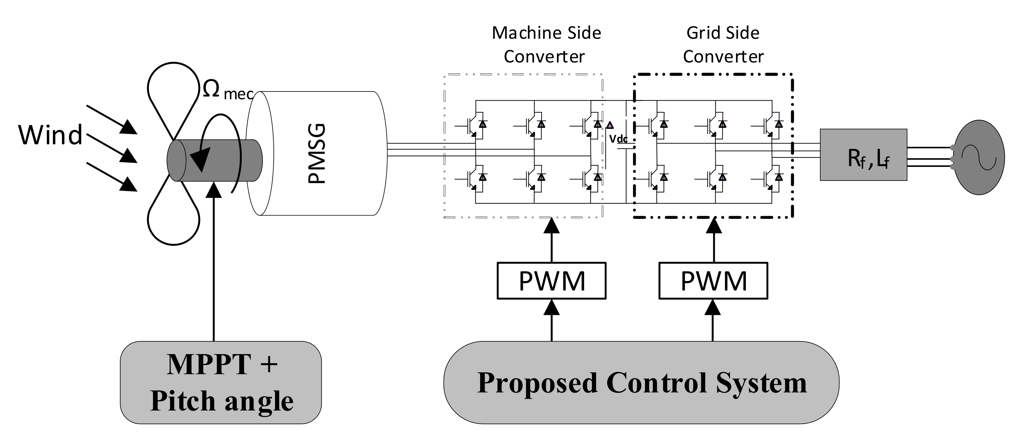
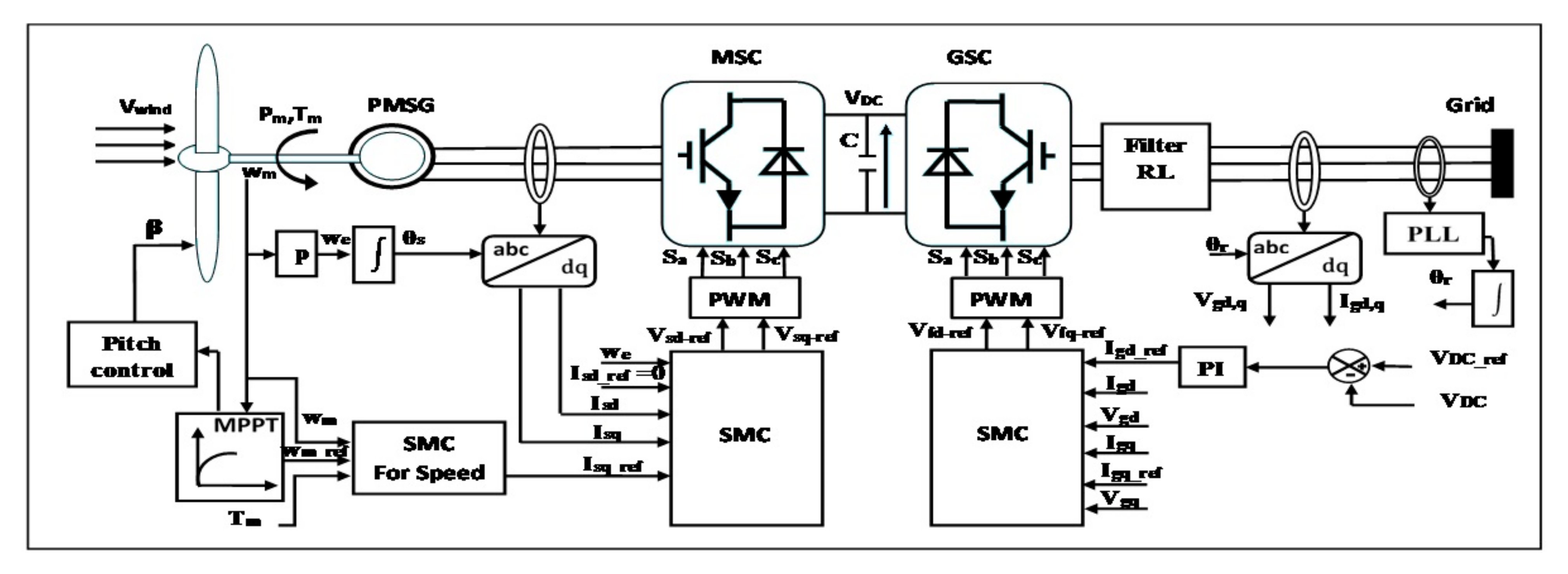
2. Wind Power System Model
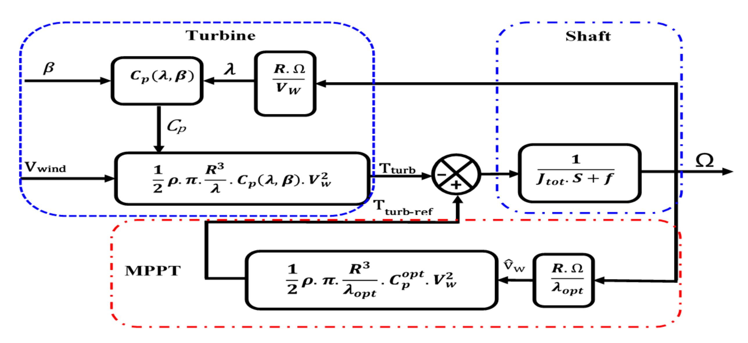
2.1. Wind Turbine Model
2.2. Maximum Power Extraction
2.3. Permanent Magnet Synchronous Generator Model
2.4. Filter (R, L) and Grid Model
3. Synthesis of Control
3.1. Description Model
- is the state vector.
- is the control variable.
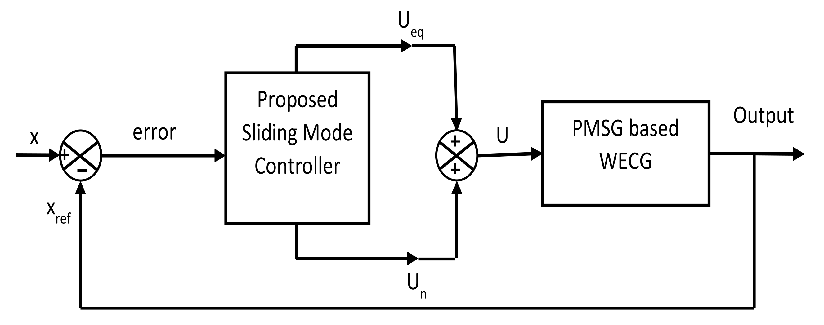
3.2. Sliding Mode Controller Design
3.2.1. Machine Side Converter Control MSC
3.2.2. Grid Side Converter Control
3.3. Stability Analysis of the Proposed SMC
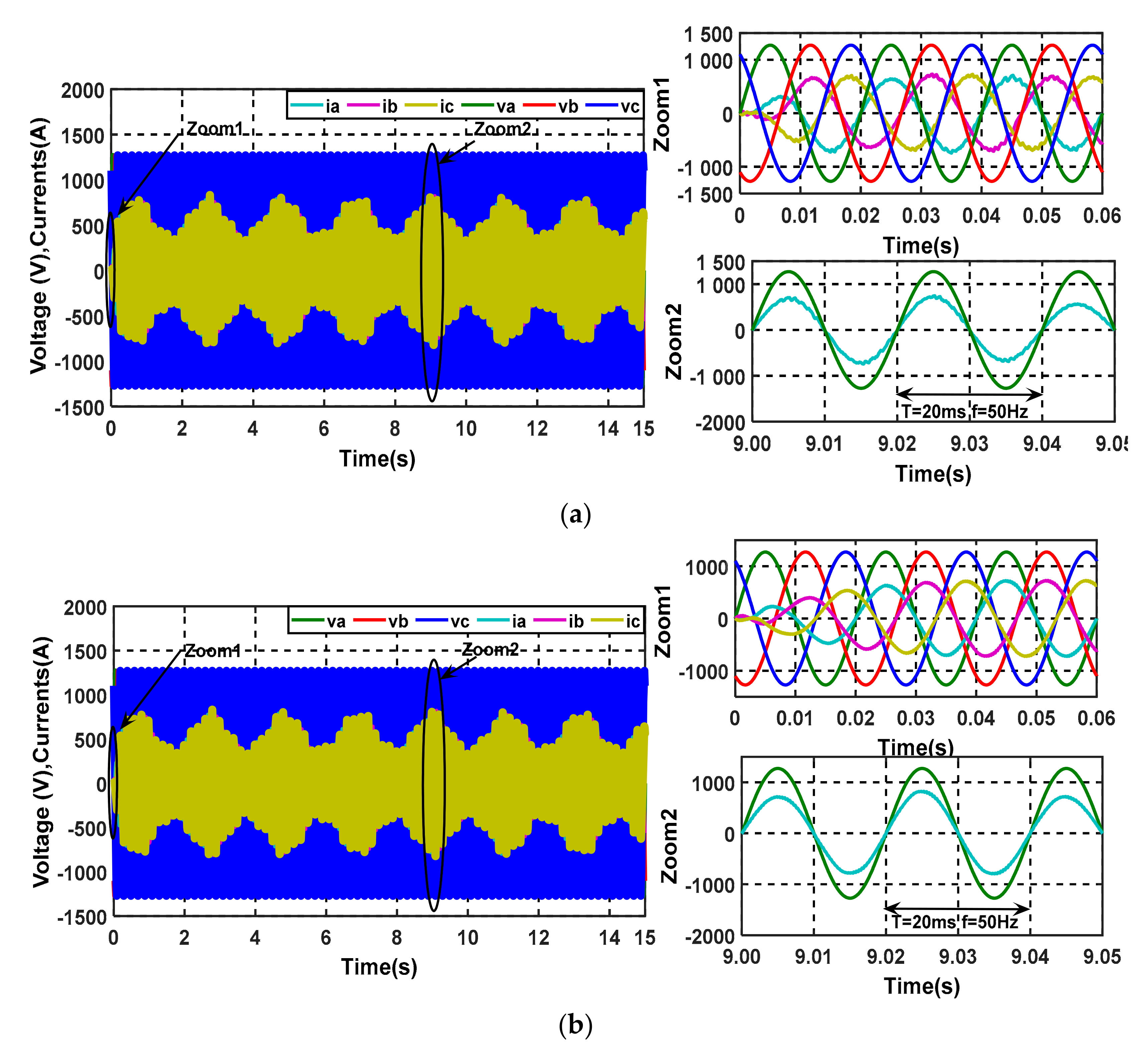
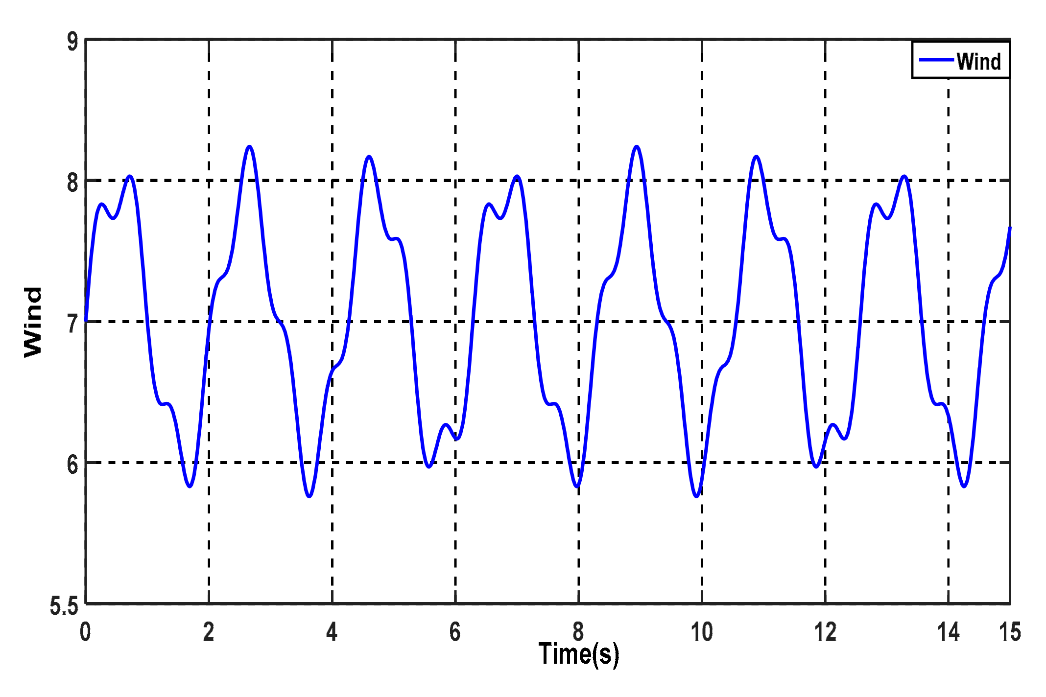
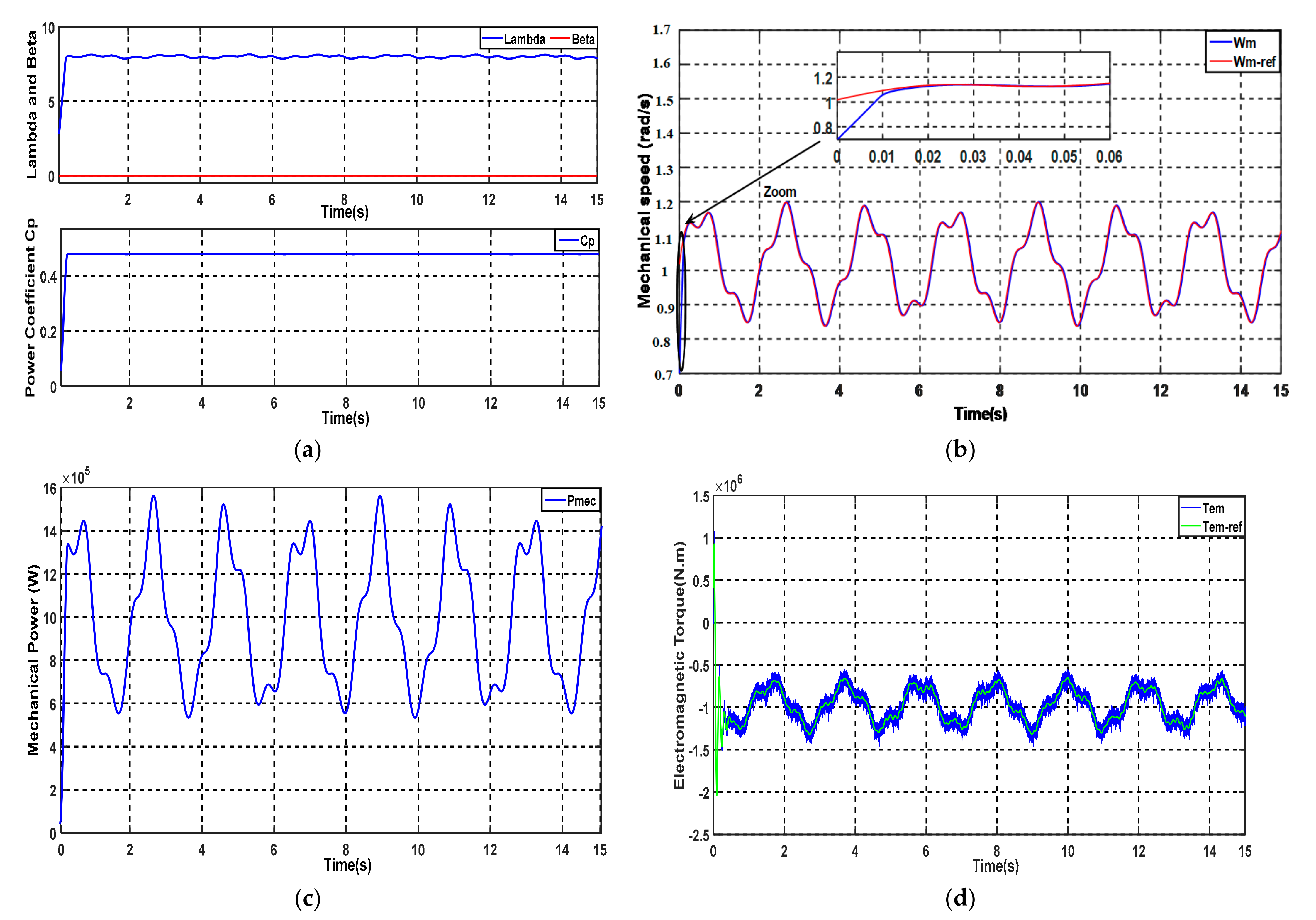
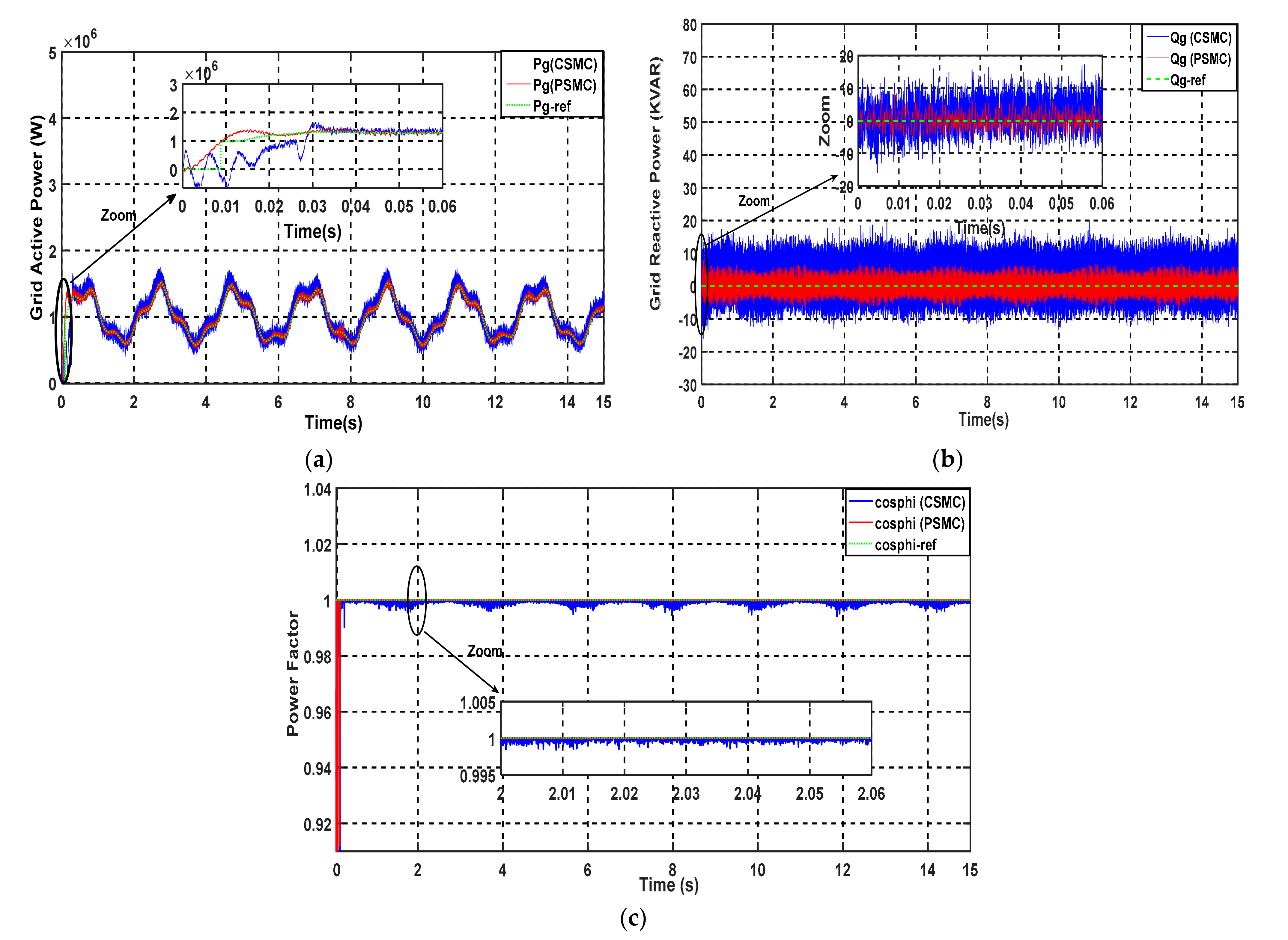
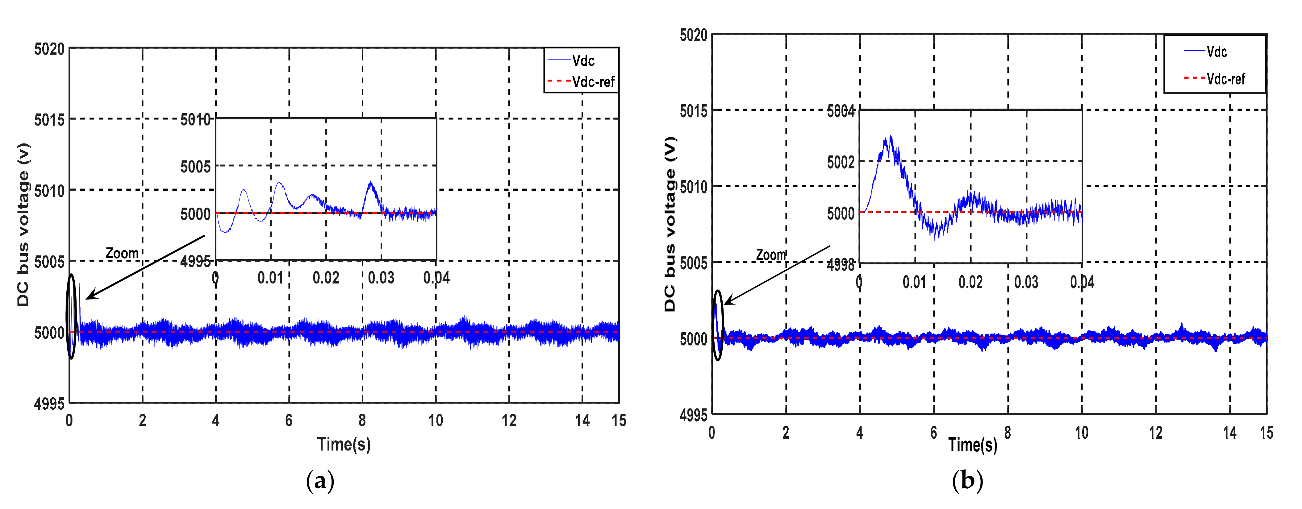
4. Simulation Results & Analysis
5. Conclusions
Author Contributions
Funding
Institutional Review Board Statement
Informed Consent Statement
Data Availability Statement
Acknowledgments
Conflicts of Interest
Nomenclature
| Ωt | Turbine speed |
| β | Pitch angle |
| ρ | Air density |
| S | Surface |
| Rs | Resistances of the stator |
| Ld, Lq, | d,q-axisInductances |
| Tem, Cem | Electromagnetic torque |
| Cr | Load torque available at a motor shaft |
| (vsd, vsq), (isd, isq), (ψsd,ψsq,) | d/q stator voltages, currents, and fluxes |
| (vgd, vgq), (igd, igq) | d/q grid voltages and currents |
| (vfd, vfq), (ifd, ifq) | Voltages and currents at the RL filter |
| Vdc | DC link voltage |
| Pgen, Pg | Generator and grid Active power |
| Qgen, Qg | Generator and grid reactive power |
Appendix A

| PMSG Parameters | Wind Turbine Parameters | ||
|---|---|---|---|
| Power Generator P | P = 2 MW | Radius of the turbine blade | R = 55 m |
| Number of pole | p = 75 | Turbine and generator inertia moment | J = 1000 N.m |
| Stator Resistance | Rs = 0.00625 Ω | Density of air | ρ = 1.22 Kg/m3 |
| d-axis inductance | Ld = 0.004229 h | Tip speed Ratio | λ = 8 |
| q-axis inductance | Lq = 0.004229 h | Optimal Power Coefficient | Cp = 0.5 |
| Generator flux | Øf = 11.1464 wb | ||
| Controller Parameters | |
|---|---|
| Kd | 10 |
| Kq | 30 |
| Kfd | 500 |
| Kfq | 100 |
References
- Bossoufi, B.; Karim, M.; Taoussi, M.; Aroussi, H.A.; Bouderbala, M.; Motahhir, S.; Camara, M.B. DSPACE-based implementation for observer backstepping power control of DFIG wind turbine. IET Electr. Power Appl. 2020, 14, 2395–2403. [Google Scholar] [CrossRef]
- Youness, E.M.; Aziz, D.; Abdelaziz, E.G.; Jamal, B.; Najib, E.O.; Othmane, Z.; Khalid, M.; Bossoufi, B. Implementation and validation of backstepping control for PMSG wind turbine using dSPACE controller board. Energy Rep. 2019, 5, 807–821. [Google Scholar] [CrossRef]
- Hong, C.M.; Chen, C.H.; Tu, C.S. Maximum power point tracking-based control algorithm for PMSG wind generation system without mechanical sensors. Energy Convers. Manag. 2013, 69, 58–67. [Google Scholar] [CrossRef]
- Benamor, A.; Benchouia, M.T.; Srairi, K.; Benbouzid, M.E.H. A novel rooted tree optimization apply in the high order sliding mode control using super-twisting algorithm based on DTC scheme for DFIG. Int. J. Electr. Power Energy Syst. 2019, 108, 293–302. [Google Scholar] [CrossRef]
- Pan, C.; Shao, L. Wind energy conversion systems analysis of PMSG on offshore wind turbine using improved SMC and Extended State Observer. Renew. Energy 2020, 161, 149–161. [Google Scholar] [CrossRef]
- Bounar, N.; Labdai, S.; Boulkroune, A. PSO–GSA based fuzzy sliding mode controller for DFIG-based wind turbine. ISA Trans. 2019, 85, 177–188. [Google Scholar] [CrossRef] [PubMed]
- Liu, J.; Zhou, F.; Zhao, C.; Wang, Z.; Aguirre-Hernandez, B. A PI-type sliding mode controller design for PMSG-based wind turbine. Complexity 2019, 2019, 2538206. [Google Scholar] [CrossRef] [Green Version]
- Soliman, M.A.; Hasanien, H.M.; Azazi, H.Z.; El-Kholy, E.E.; Mahmoud, S.A. An adaptive fuzzy logic control strategy for performance enhancement of a grid-connected PMSG-Based wind turbine. IEEE Trans. Ind. Inform. 2019, 15, 3163–3173. [Google Scholar] [CrossRef]
- Beddar, A.; Bouzekri, H.; Babes, B.; Afghoul, H. Experimental enhancement of fuzzy fractional order PI+I controller of grid connected variable speed wind energy conversion system. Energy Convers. Manag. 2016, 123, 569–580. [Google Scholar] [CrossRef]
- Aounallah, T.; Essounbouli, N.; Hamzaoui, A.; Bouchafaa, F. Algorithm on fuzzy adaptive backstepping control of fractional order for doubly-fed induction generators. IET Renew. Power Gener. 2018, 12, 962–967. [Google Scholar] [CrossRef]
- Yin, W.; Wu, X.; Rui, X. Adaptive robust backstepping control of the speed regulating differential mechanism for wind turbines. IEEE Trans. Sustain. Energy 2019, 10, 1311–1318. [Google Scholar] [CrossRef]
- Beniysa, M.; Idrissi, A.E.J.E.; Bouajaj, A.; Britel, M.R.; Ariwa, E. Neural network adaptive backstepping control via uncertainty compensation for PMSG-based variable-speed wind turbine: Controller design and stability analysis. Wind Eng. 2021. [Google Scholar] [CrossRef]
- Matraji, I.; Al-Durra, A.; Errouissi, R. Design and experimental validation of enhanced adaptive second-order SMC for PMSG-based wind energy conversion system. Int. J. Electr. Power Energy Syst. 2018, 103, 21–30. [Google Scholar] [CrossRef]
- Xiong, L.; Li, P.; Ma, M.; Wang, Z.; Wang, J. Output power quality enhancement of PMSG with fractional order sliding mode control. Int. J. Electr. Power Energy Syst. 2020, 115, 105402. [Google Scholar] [CrossRef]
- Hostettler, J.; Wang, X. Sliding mode control of a permanent magnet synchronous generator for variable speed wind energy conversion systems. Syst. Sci. Control Eng. 2015, 3, 453–459. [Google Scholar] [CrossRef]
- Gautam, K.K.; Sankaranarayanan, V. Sliding mode control of surface mounted permanent magnet synchronous generator. IFAC Proc. Vol. 2014, 47, 1034–1038. [Google Scholar] [CrossRef]
- Ayadi, M.; Ben Salem, F.; Derbel, N. Sliding mode approach for blade pitch angle control wind turbine using PMSG under DTC. In Proceedings of the 2015 16th International Conference on Sciences and Techniques of Automatic Control and Computer Engineering (STA), Monastir, Tunisia, 21–23 December 2015; pp. 758–762. [Google Scholar] [CrossRef]
- Haq, I.U.; Khan, M.I.; Zeb, K. Siding Mode Control for PMSG based Wind Energy Conversion System connected to the grid. In Proceedings of the 2016 International Conference on Computing, Electronic and Electrical Engineering (ICE Cube), Quetta, Pakistan, 11–12 April 2016; pp. 277–282. [Google Scholar] [CrossRef]
- Benelghali, S.; Benbouzid, M.E.H.; Charpentier, J.F.; Ahmed-Ali, T.; Munteanu, I. Experimental validation of a marine current turbine simulator: Application sliding mode control. IEEE Trans. Ind. Electron. 2011, 58, 118–126. [Google Scholar] [CrossRef] [Green Version]
- Errouissi, R.; Al-Durra, A. A Novel PI-Type Sliding Surface for PMSG-Based Wind Turbine with Improved Transient Performance. IEEE Trans. Energy Convers. 2018, 33, 834–844. [Google Scholar] [CrossRef]
- Phan, D.H.; Huang, S.D. Super-twisting sliding mode control design for cascaded control system of pmsg wind turbine. J. Power Electron. 2015, 15, 1358–1366. [Google Scholar] [CrossRef]
- Jaramillo-Lopez, F.; Kenne, G.; Lamnabhi-Lagarrigue, F. A novel online training neural network-based algorithm for wind speed estimation and adaptive control of PMSG wind turbine system for maximum power extraction. Renew. Energy 2016, 86, 38–48. [Google Scholar] [CrossRef]
- El Mourabit, Y.; Derouich, A.; Allouhi, A.; El Ghzizal, A.; El Ouanjli, N.; Zamzoumyes, O. Sustainable production of wind energy in the main Morocco’s sites using permanent magnet synchronous generators. Int. Trans. Electr. Energ. Syst. 2020, 30, e12390. [Google Scholar] [CrossRef]
- Yin, X.-X.; Lin, Y.-G.; Li, W.; Gu, Y.-J.; Liu, H.-W.; Lei, P.-F. A novel fuzzy integral sliding mode current control strategy for maximizing wind power extraction and eliminating voltage harmonics. Energy Elsevier 2015, 85, 677–686. [Google Scholar] [CrossRef]
- Meghni, B.; Dib, D.; Azar, A.T. A second-order sliding mode and fuzzy logic control to optimal energy management in wind turbine with battery storage. Neural Comput. Appl. 2017, 28, 1417–1434. [Google Scholar] [CrossRef]
- Beltran, B.; Benbouzid, M.E.H.; Ahmed-Ali, T. Second-Order Sliding Mode Control of a Doubly Fed Induction Generator Driven Wind Turbine. IEEE Trans. Energy Convers. 2012, 27, 261–269. [Google Scholar] [CrossRef] [Green Version]
- Yang, B.; Yu, T.; Shu, H.; Dong, J.; Jiang, L. Robust Sliding-mode Control of Wind Energy Conversion Systems for Optimal Power Extraction via Nonlinear Perturbation Observers. Appl. Energy 2018, 210, 711–723. [Google Scholar] [CrossRef]
- Benamor, A.; Benchouia, M.T.; Srairi, K.; Benbouzid, M.E.H. A new rooted tree optimization algorithm for indirect power control a wind turbine based on a powered double induction generator. ISA Trans. 2019, 88, 296–306. [Google Scholar] [CrossRef]
- Freire, N.; Estima, J.; Cardoso, A. A Comparative Analysis of PMSG Drives Based on Vector Control and Direct Control Techniques for Wind Turbine Applications. Electr. Rev. 2012, 88, 184–187. [Google Scholar]
- Zribi, M.; Alrifai, M.; Rayan, M. Sliding Mode Control of a Variable—Speed Wind Energy Conversion System Using a Squirrel Cage Induction Generator. Energies 2017, 10, 604. [Google Scholar] [CrossRef] [Green Version]
- Gonzalez, L.; Figueres, E.; Garcera, G.; Carranza, O. Maximum-power-point tracking with reduced mechanical stress applied to wind energy conversion systems. Appl. Energy 2010, 87, 2304–2312. [Google Scholar] [CrossRef] [Green Version]
- Mousa, H.H.; Youssef, A.R.; Mohamed, E.E. Model predictive speed control of five-phase permanent magnet synchronous generator-based wind generation system via wind-speed estimation. Int. Trans. Electr. Energy Syst. 2019, 29, e2826. [Google Scholar] [CrossRef]
- Jena, N.K.; Mohanty, K.B.; Pradhan, H.; Sanyal, S. A comparison between PI SMC used for decoupled control of PMSG in a variable speed wind energy system. In Proceedings of the 2015 International Conference on Energy, Power and Environment: Towards Sustainable Growth (ICEPE), Shillong, India, 12–13 June 2015; pp. 1–6. [Google Scholar]
- Jin, N.; Wang, X.; Wu, X. Current Sliding Mode Control with a Load Sliding Mode Observer for Permanent Magnet Synchronous Machines. J. Power Electron. 2014, 14, 105–114. [Google Scholar] [CrossRef] [Green Version]
- Bossoufi, B.; Karim, M.; Lagrioui, A.; Taoussi, M.; Derouich, A. Observer Backstepping control of DFIG-Generators for Wind Turbines Variable-Speed: FPGA-Based Implementation. Renew. Energy J. 2015, 81, 903–917. [Google Scholar] [CrossRef]
- Rhaili, S.E.; Abbou, A.; Marhraoui, S.; Moutchou, R.; El Hichami, N. Robust Sliding Mode Control with Five Sliding Surfaces of Five-Phase PMSG Based Variable Speed Wind Energy Conversion System. Int. J. Intell. Eng. Syst. 2020, 13, 346–357. [Google Scholar] [CrossRef]
- Mousa, H.H.H.; Youssef, A.R.; Mohamed, E.E.M. Optimal Power Extraction Control Schemes for Five-Phase PMSG Based Wind Generation Systems. Eng. Sci. Technol. Int. J. 2020, 23, 144–155. [Google Scholar] [CrossRef]
- Rhaili, S.E.; Abbou, A.; Hichami, N.E.; Marhraoui, S.; Chojaa, H. Mawimum power extraction of five-phase PMSG WECS by adopting and improved fractional order sliding mode strategy. Jilin DaxueXuebao 2021, 55–74. [Google Scholar] [CrossRef]
- Bouderbala, M.; Bossoufi, B.; Deblecker, O.; AlamiAroussi, H.; Taoussi, M.; Lagrioui, A.; Motahhir, S.; Masud, M.; Alraddady, F.A. Experimental Validation of Predictive Current Control for DFIG: FPGA Implementation. Electronics 2021, 10, 2670. [Google Scholar] [CrossRef]
- Bossoufi, B.; Karim, M.; Taoussi, M.; AlamiAroussi, H.; Bouderbala, M.; Debleckler, O.; Motahhir, S.; Nayyar, A.; Massud, M. Rooted Tree Optimization for Backstepping Power Control of DFIG Wind Turbine: dSPACE Implementation. IEEE Access 2021, 9, 26512–26522. [Google Scholar] [CrossRef]
- AlamiAroussi, H.; El Ziani, M.; Bouderbala, M.; Bossoufi, B. Enhancement of the direct power control applied to DFIG-WECS. Int. J. Electr. Comput. Eng. 2020, 10, 1511–1520. [Google Scholar]
- Hammoumi, D.; Bakkali, C.E.L.; Karim, M.; Taoussi, M.; Ouanjli, N.E.L.; Bossoufi, B. Direct controls for wind turbine with PMSG used on the real wind profile of Essaouira-Morocco city. Indones. J. Electr. Eng. Comput. Sci. 2019, 16, 1229–1239. [Google Scholar] [CrossRef]
- Aroussi, H.A.; El Ziani, M.; Bouderbala, M.; Bossoufi, B. Improvement of Direct Torque Control Applied To Doubly Fed Induction Motor under Variable Speed. IJPEDS Int. J. Power Electron. Drive Syst. 2020, 11, 1511–1520. [Google Scholar] [CrossRef] [Green Version]
- El Mahfoud, M.; Bossoufi, B.; ElOunjli, N.; Mahfoud, S.; Taoussi, M. Improved Direct Torque Control of Doubly Fed Induction Motor Using Space Vector Modulation. Int. J. Intell. Eng. Syst. 2021, 14, 177–188. [Google Scholar] [CrossRef]
- El Karaoui, I.; Maaroufu, M.; Bossoufi, B. Fuzzy Sliding Mode Power Control for Wind Power Generation System Connected to the Grid. IJPEDS Int. J. Power Electron. Drive Syst. 2021, 11, 11–25. [Google Scholar]
- Majout, B.; Abrahimi, D.; Ihedrane, Y.; El Bakkali, C.; Karim, M.; Bossoufi, B. Improvement of Sliding Mode Power Control Applied to Wind Power Generation system based on DFIG. IJPEDS Int. J. Power Electron. Drive Syst. 2021, 12, 441–452. [Google Scholar]
- Zine Laabidine, N.; Errahout, A.; Bakkali, C.E.L.; Karim, M.; Bossoufi, B. Sliding Mode Control Design of Wind Power Generation system based on PMSG. IJPEDS Int. J. Power Electron. Drive Syst. 2021, 12, 393–403. [Google Scholar]


| Performance | CSMC Technique | PSMC Technique |
|---|---|---|
| Set-point tracking % | 80 | 99 |
| Error % | 0.31 | 0.15 |
| Response time Vdc (ms) | 32 | 22 |
| Overshoot of Vdc % | 0.096 | 0.05 |
| Variation band of Qr (KVAR) | 25 | 15 |
| Power efficiency (Pr/Pmec) % | 99.60 | 99.75 |
| Power Factor | 1 | 1 |
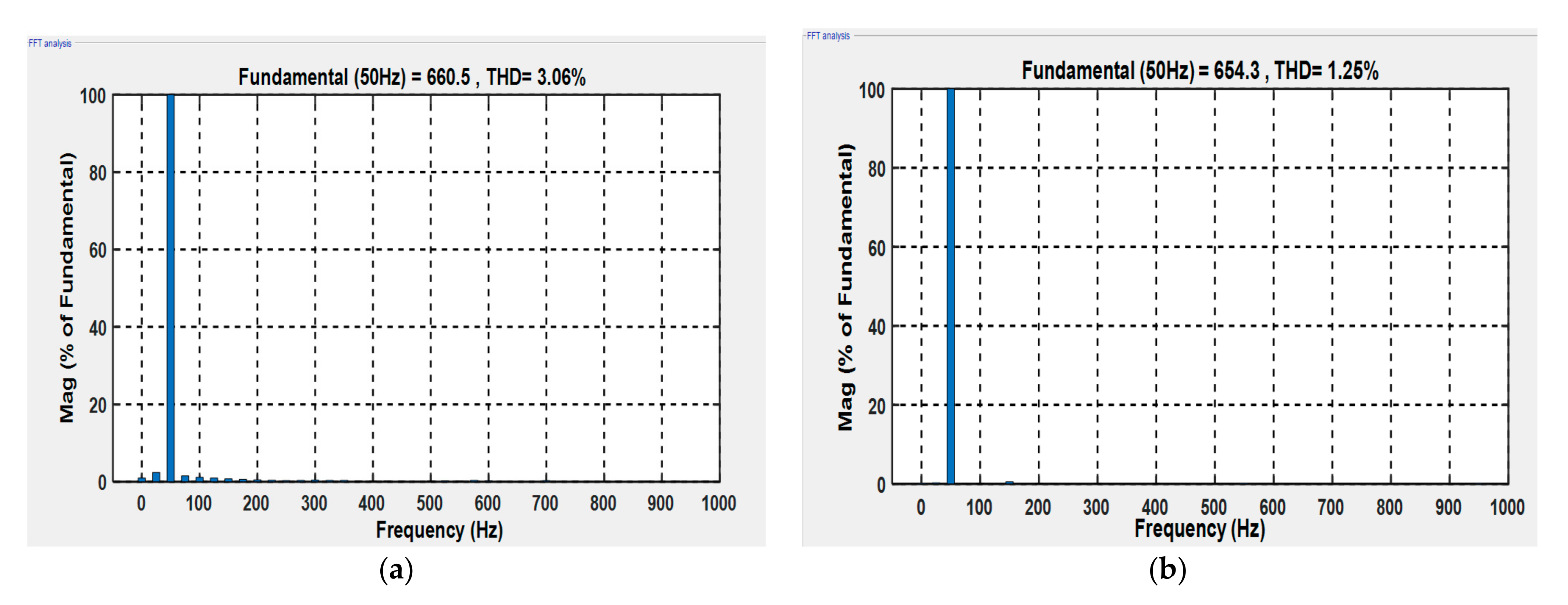
| THD of injected current (%) | 3.06 | 1.25 |
| Publication | Technic methods | Efficiency | Error | Overshot | Cosφ | Robustness |
|---|---|---|---|---|---|---|
| [34] | PI neural controller | 93.5 | 0.15% | 0% | 0.997 | Moderate-high |
| PI Fuzzy controller | 93.99 | 0.14% | 0% | 0.974 | Moderate-high | |
| [28] | DTC-classical | 92.13 | 0.32% | 5% | 0.983 | Moderate-high |
| DTC-GA-based PI | 92.07 | 0.12% | 1% | 0.978 | Moderate-high | |
| [36] | SMC | 91.14% | 0.3% | - | - | Medium |
| [37] | Integral SMC | 92.45% | 0.2% | - | - | High |
| [38] | Fractionalorder SMC | 98.6% | 0.3% | - | - | High |
| Proposal technique | PSMC | 98.99 | 0.12% | 0% | 0.995 | High |
Publisher’s Note: MDPI stays neutral with regard to jurisdictional claims in published maps and institutional affiliations. |
© 2022 by the authors. Licensee MDPI, Basel, Switzerland. This article is an open access article distributed under the terms and conditions of the Creative Commons Attribution (CC BY) license (https://creativecommons.org/licenses/by/4.0/).
Share and Cite
Majout, B.; Bossoufi, B.; Bouderbala, M.; Masud, M.; Al-Amri, J.F.; Taoussi, M.; El Mahfoud, M.; Motahhir, S.; Karim, M. Improvement of PMSG-Based Wind Energy Conversion System Using Developed Sliding Mode Control. Energies 2022, 15, 1625. https://doi.org/10.3390/en15051625
Majout B, Bossoufi B, Bouderbala M, Masud M, Al-Amri JF, Taoussi M, El Mahfoud M, Motahhir S, Karim M. Improvement of PMSG-Based Wind Energy Conversion System Using Developed Sliding Mode Control. Energies. 2022; 15(5):1625. https://doi.org/10.3390/en15051625
Chicago/Turabian StyleMajout, Btissam, Badre Bossoufi, Manale Bouderbala, Mehedi Masud, Jehad F. Al-Amri, Mohammed Taoussi, Mohammed El Mahfoud, Saad Motahhir, and Mohammed Karim. 2022. "Improvement of PMSG-Based Wind Energy Conversion System Using Developed Sliding Mode Control" Energies 15, no. 5: 1625. https://doi.org/10.3390/en15051625
APA StyleMajout, B., Bossoufi, B., Bouderbala, M., Masud, M., Al-Amri, J. F., Taoussi, M., El Mahfoud, M., Motahhir, S., & Karim, M. (2022). Improvement of PMSG-Based Wind Energy Conversion System Using Developed Sliding Mode Control. Energies, 15(5), 1625. https://doi.org/10.3390/en15051625