Article

Comprehensive Analysis for Electromagnetic Shielding Method Based on Mesh Aluminium Plate for Electric Vehicle Wireless Charging Systems

1
State Grid Electric Power Research Institute, Nanjing 211100, China
2
College of Automation, Chongqing University, Chongqing 400045, China
*
Author to whom correspondence should be addressed.
Energies 2022, 15(4), 1546; https://doi.org/10.3390/en15041546
Submission received: 28 December 2021 / Revised: 8 February 2022 / Accepted: 14 February 2022 / Published: 19 February 2022
(This article belongs to the Special Issue Advances in Electric Vehicle Wireless Charging Systems)

Abstract

:
As an epoch-making technique, wireless power transfer (WPT) technology has been used in electric vehicle charging devices in recent years, but the electromagnetic leakage problem has always plagued numerous researchers. The traditional wireless charging systems use a solid metal aluminium plate to shield electromagnetic leakage generally. Although it has a good shielding performance, it will seriously reduce the transmission efficiency of wireless charging systems. In this paper, an aluminium plate with a series of mesh holes of different sizes is proposed to weaken the eddy current in partial areas on the plane. Therefore, without changing the maximum magnetic induction intensity of the shielded magnetic field, the influence of the aluminium plate on the electrical parameters of the wireless power transfer system is minimized, and the transmission efficiency of the system is improved. The Ansys Maxwell software has been adopted to simulate the transfer and shielding performance. Finally, the experimental results have verified that the optimized mesh aluminium plate can reduce the interference to the transmission performance of electric vehicle wireless charging system and further improve the electromagnetic environment of the system effectively at the same time.

1. Introduction

Wireless Power Transfer (WPT) technology is an ideal charging method for Electric Vehicles (EVs) in the future [1]. With the rapid development of informatization, intelligence and network connection of EVs, the demand for wireless charging is particularly urgent [2]. EVs wireless charging realizes contactless transmission of power energy through strong coupling resonance of transmitter and receiver. Electromagnetic noise will inevitably be generated in non-working areas. It is critical to study the electromagnetic compatibility of EVs’ wireless charging systems to eliminate the public doubts about electromagnetic noise [3,4,5].
Generally speaking, EVs’ wireless charging systems include static charging and dynamic charging. For EVs, static wireless charging system, passive shielding is widely used to shielding EM leakage at present, that is, ferromagnetic materials and conductive materials are placed around the coupling system for EM shielding. This shielding method is simple, effective and low cost. It is also widely used in EM compatibility problems of other electrical systems. At the same time, ferrite and aluminium plates are often used as magnetic shielding materials to reduce EM leakage in EVs’ wireless charging systems. Campi et al. proposed a novel design of active coil shielding to reduce the magnetic field generated by the currents flowing into the coils of WPT systems for charging the batteries of an electric vehicle [6]. Zhang et al. [7] proposed a novel ferrite shielding design to meet the demands of definitions in SAE J2954. The experimental results showed a great reduction was achieved from the scale-down test. In [8], an aluminium ring vertically surrounding the coil was proposed to cooperate with the aluminium plate to shield the leaked electromagnetic fields, which can more effectively reduce the magnetic field leakage between the WPT coils. this will increase the thickness of the coil, which is equivalent to reducing the transmission distance. In [9], magnetic shielding material for wireless charging was introduced to reduce the EM noise. Compared with metal materials, ferrite can better enhance the coupling between wireless charging coils and improve transmission efficiency [10]. Nevertheless, ferrite is dense and very fragile, so it is not suitable for use as a shield in the wireless charging device of electric vehicles.
In addition, grooves of different shapes can be added to the metal plate to suppress eddy currents on the plate to improve system efficiency, but the most effective groove shape remains to be studied. In [11], a genetic algorithm was adopted for shielding promotion and efficiency improvement in EV wireless charging applications via the optimization of IPT systems. Cui et al. [12] studied the shield structure of the coupling mechanism of electric vehicle wireless transmission systems. The paper has compared and analyzed the coupling coil loss model and transmission efficiency before and after shielding of different shield structures (plate or strip). Hariri [13] studied the influence of changing various parameters of the shielding body on transmission performance and shielding effect and proposed the use of iterative methods to design the size and thickness of shielding material. The current electromagnetic shielding method is to add a shielding material near the coil to shield the magnetic field, but it is necessary to analyze the influence of the materials on the WPT system [14,15].
Considering the respective advantages of metal and ferrites, sometimes they are used in combination [16]. This will obviously increase the weight and cost of the wireless charging device. In fact, for the clear majority of EVs’ wireless charging systems, ferrite is an essential part of the coupling mechanism design, which can not only shield the magnetic leakage in the working area, but also improve the coupling strength between the transmitter and receiver, further improving the transmission performance of the systems. From the perspective of economy and energy consumption, the compact design of the coupling mechanism (especially the vehicle-mounted coil) is particularly important, which requires the volume and weight of the receiving coil [17]. However, the effect of ferrite on the non-working area of EM shielding is more general, ferrite density is high, and the cost is very high. The Metallic aluminium plate has a good shielding effect on the electromagnetic field in the non-working area, with a small density and relatively cheap price. Therefore, the optimal design and reasonable placement of the shielding aluminium plate become key to the EM compatibility of EVs’ wireless charging systems.
Firstly, the EM field action mechanism and equivalent circuit modelling of aluminium plate loaded by resonant coil are analyzed in this paper, and the shielding effect of the aluminium plate on the resonant coil is briefly summarized theoretically. Then, the simulation results have been compared to the wireless charging system with a solid aluminium plate or the mesh aluminium plate and explore the influence of the hole size and shape on the electromagnetic shielding ability of the aluminium plate and the wireless charging efficiency. In addition, emphasis is put on the simulation analysis of changing the aperture shape and size of the mesh aluminium plate, and the influence of different structure mesh aluminium plates on the impedance change, transmission characteristics and shielding effect of the system is studied. Finally, an aluminium plate with holes of different diameters was proposed as a shielding material for leaking electromagnetic fields. By adding a series of mesh holes of different sizes on the board, it can reduce its impact on the efficiency of the wireless charging system without affecting its original electromagnetic shielding ability and reduce the overall weight and cost. The main contributions of this paper are as follows.
(1)
The EM shielding of the EV wireless charging system by the solid aluminium plate will have a great impact on the transmission performance of the system. The mesh aluminium plate can effectively weaken the performance changes brought by the introduction of the shielding body to the transmission system, and can effectively carry out EM shielding of EV wireless charging systems.
(2)
The results show that the denser the mesh, the greater the influence on the system and the better the shielding effect. Unequal and non-uniform structures and arrangements can be used to achieve the best balance between the shielding effect and transmission performance.

2. Theoretical Analysis and Simulation

2.1. Influence of Metal Plate on Coil Parameters

The metal shielding plate will generate induced eddy currents under the action of the alternating magnetic field of the WPT system. The magnetic field generated by the eddy current is 180° out of phase with the original magnetic field, so it can weaken the original magnetic field. Therefore, the metal plate can shield the electromagnetic field. At the same time, there is a coupling between the eddy current loop and the shielded coil, which will change the parameters of the latter. As shown in Figure 1, the metal shielding plate is equivalent to a series circuit of resistance and inductance, and the Kirchhoff voltage equation is listed according to the coupling relationship between the metal plate and the shielded coil, where Rc, Lc and Cc are the resistance, inductance and compensation capacitance of the coil, Rp and Lp are the equivalent resistance and inductance of the metal plate, and Mcp is the mutual inductance between the equivalent circuit of the coil and the metal plate.
{ I C ( R C + j ω L C + 1 j ω C C ) + j ω M C P I P = V S j ω M C P I C + I P ( R P + j ω L C ) = 0
Thus, the circuit parameter expression of the wireless charging coil in the presence of the metal shielding plate can be solved as follows:
{ R C = R C + ω 2 M C a 2 R a 2 + ω 2 L a 2 R a = R C + R L C = L C ω 2 M C a 2 R a 2 + ω 2 L a 2 ω L a = L C + L
It can be seen that the resistance of the coil has increased compared to the original condition, which leads to increased losses during the WPT process and reduced system efficiency. In addition, the equivalent inductance of the coil is reduced, which means that the resonant frequency of the coil is offset from the original operating frequency fS.
f S = 1 2 π L C C C 1 2 π L C C C

2.2. WPT System with Shield Plates on Both Receiving and Sending Sides

At present, the research on EM compatibility and safety issues of EVs’ wireless charging systems is still in its infancy. The field circuit structure of a typical two-coil WPT system is shown in Figure 2. Among them, the DC power supply generates high-frequency alternating current through a full-bridge inverter, and then flows through the transmitting end compensation capacitor Cs to drive the transmitter, and its current generates high frequency The EM field is coupled to the receiver by magnetic induction, and the coupled induction current flows through the receiving end compensation capacitor Cr, and supplies power to the load after being rectified and filtered. Shielding aluminium plates are placed on both sides of the resonant coil to suppress EM leakage.
Then, the wireless charging system with a transmitter coil (TX Coil) and receiver coil (RX Coil) both equipped with metal shielding plate is further equivalent to the four-coil system as shown in Figure 3. R1, L1 and C1 are the resistance, inductance and compensation capacitance of the TX coil, R2, L2 and C2 are the resistance, inductance and compensation capacitance of the RX coil, R0 and L0 are the equivalent resistance and equivalent inductance of the shielding aluminium plate, and RL is the load resistance of the receiving end. M01 and M02 are the mutual inductance between the TX coil and the aluminium plate on the transmitting side, and the mutual inductance between the RX coil and the aluminium plate on the receiving side. M12’ is the mutual inductance between the two coils after adding the shielding material. Due to the distance, the mutual inductance between the RX coil and the plate on the sending side is ignored. Similarly, the mutual inductance between the TX coil and the plate on the receiving side and the mutual inductance between the two plates are also ignored. The parametric equation is listed according to the above equivalent circuit diagram:
[ R 0 + j ω L 0 j ω M 10 0 0 j ω M 10 R 1 + j ω L 1 + 1 j ω C 1 j ω M 12 0 0 j ω M 12 R 2 + R L + j ω L 2 + 1 j ω C 2 j ω M 20 0 0 j ω M 20 R 0 + j ω L 0 ] [ I P 1 I 1 I 2 I P 2 ] = [ 0 U 0 0 ]
where I1, I2, IP1 and IP2 are the current flowing through each circuit respectively. When the shielded aluminium plate is added to the WPT systems, the resistance of the coil will increase, the inductance will decrease, and the influence on the capacitance can be ignored, resulting in the deviation of the natural resonance frequency, that is, when the frequency aluminium plate is added, the resonance frequency is
f = 1 2 π ( L + L ) C
Finally, the transmission efficiency expression of the wireless charging system with shielding board can be obtained:
η = ( ω 0 M 12 ) 2 R L ( R 2 + R L ) [ R 1 ( R 2 + R L ) + ( ω 0 M 12 ) 2 ]
In combination with Equations (2) and (5), it can be seen that the electric vehicle wireless charging system loaded with shielding materials has a complex model and various parameters. In particular, it is difficult to analyse the nonlinear effect of shielding material on the coil parameters numerically, so it can only be analysed qualitatively. Therefore, three-dimensional finite element simulation software is mostly used to model and analyse the wireless charging system of electric vehicles.

3. Simulation and Experiment

3.1. Effect of Mesh Shape on System

For the EVs wireless charging system with shielding materials, in the process of simulation modelling, the model can be carried out according to the size and geometric parameters of the actual charging system, and then the impedance variation and transmission parameters of the system are analyzed. However, the EV wireless transmission systems work in the magnetic quasi-static field and can ignore the displacement current density. In the finite element simulation model, the correlation vectors all satisfy the Maxwell equation. Through the finite element simulation software, the electrical parameters of the coil after loading the shielded aluminium plate and the magnetic field intensity at any point in space can be obtained, which provides theoretical guidance for subsequent experiments. In this paper, Ansys Maxwell was used to simulate the wireless charging system without a shielding plate and the wireless charging system with a mesh plate.
Thanks to the inspiration of the electrostatic shielding of the metal mesh cover and the honeycomb shielding ventilation plate of the desktop computer, electromagnetic shielding can be achieved by drilling holes in the metal aluminium plate. It can not only achieve the EM shielding effect and reduce the impact on the transmission performance of the system, but it can also reduce the weight of the aluminium plate, avoid material waste, and has obvious advantages such as rebuilding, easy ventilation and heat dissipation. Therefore, this section is mainly based on the 3D electromagnetic simulation software, aiming at the electric vehicle wireless power transmission system model, and elaborates on the influence of the shape, size, thickness and loading position of the mesh aluminium plate on the charging system.
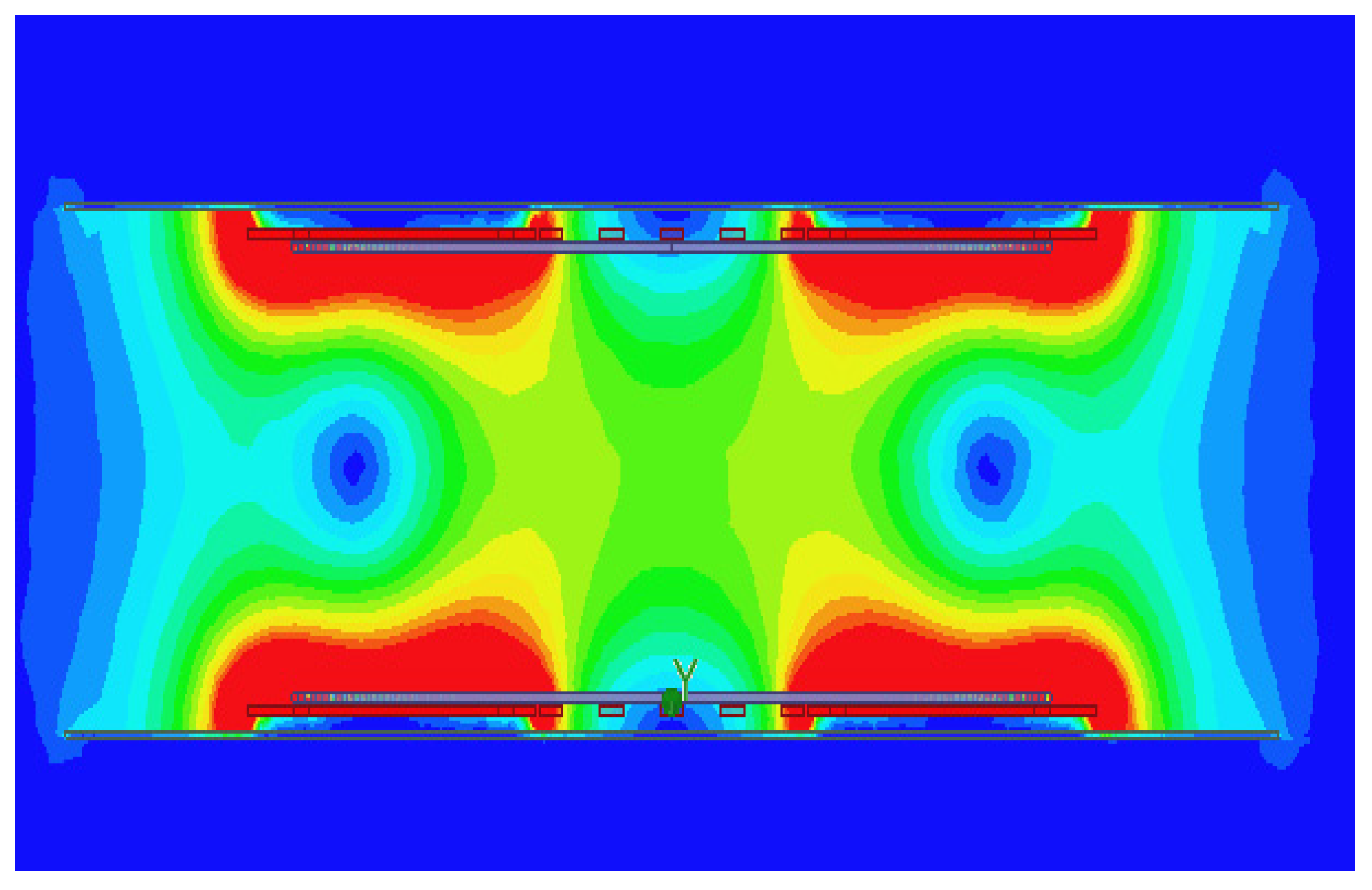
The magnetic induction intensity of the non-meshed aluminium plate electromagnetic shielding is shown in 
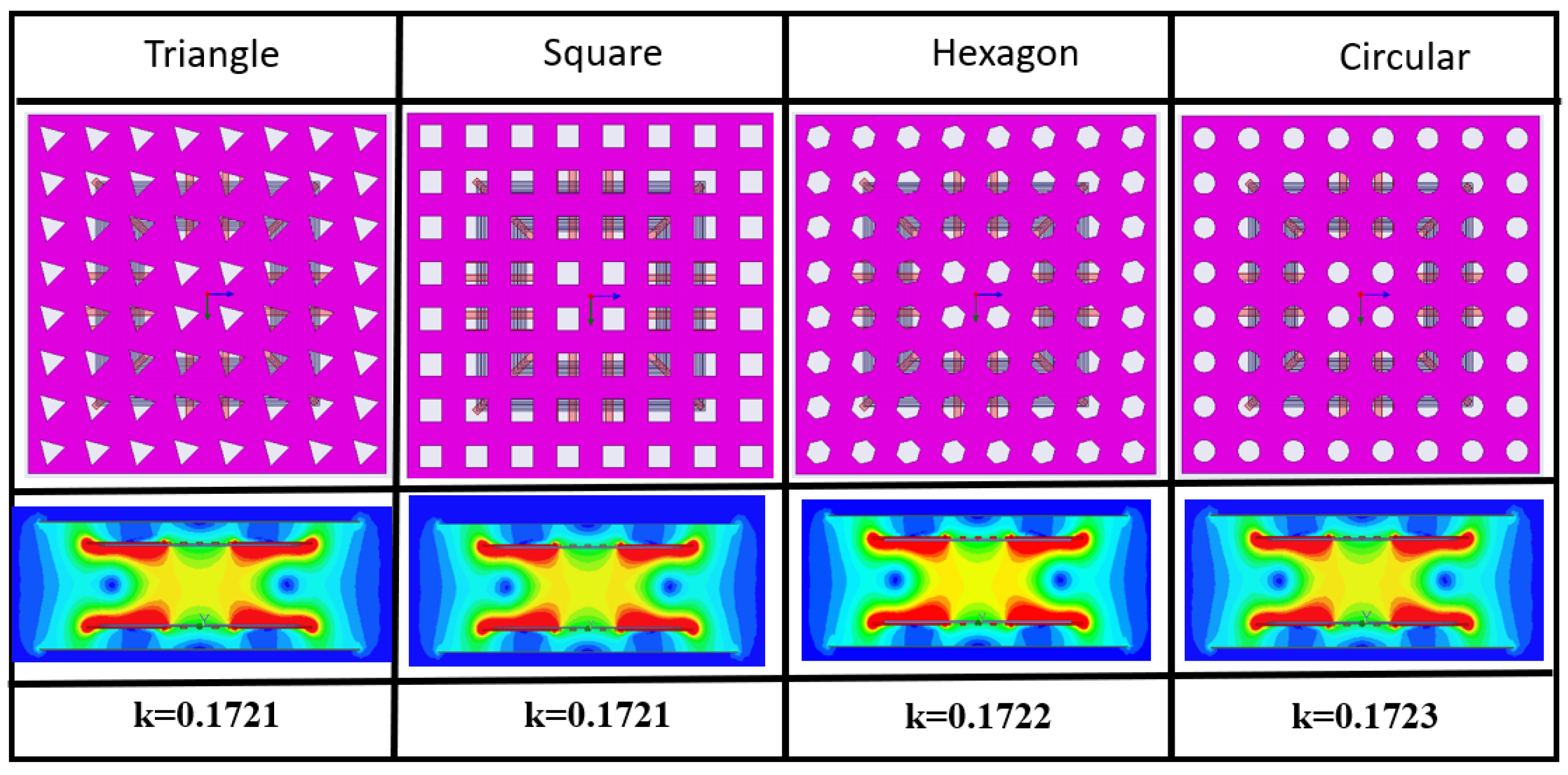
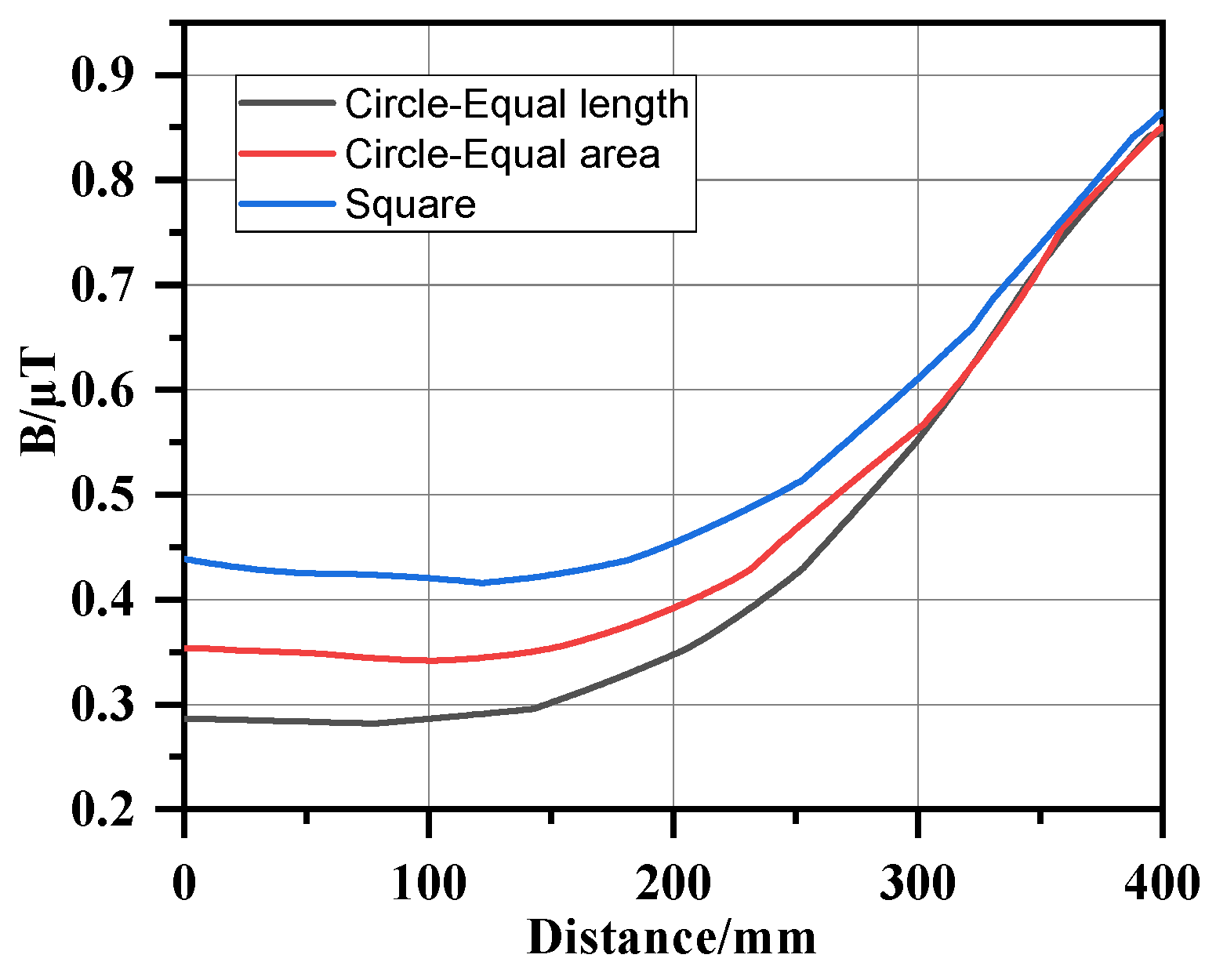
Figure 4. The coils are square spiral coils with a side length L = 50 cm. The primary coil has 13 turns and the secondary coil has 11 turns, respectively. The coil is inlaid with magnetic core material PC40 to enhance the coupling strength of the coil. The two coils are perfectly aligned, and the original charging height is H = 20 cm. It can be found the solid aluminium plane has a great shielding effect. In addition, the coupling coefficient is 0.1645 in that case. Then, different forms of mesh aluminium plates are established, and their shapes and spatial magnetic field distribution diagrams are shown in Figure 5. Taking the four shapes of triangle, square, hexagon and circle, respectively, all of which are distributed in an 8 × 8 array. It can be seen from the magnetic field distribution diagram that the magnetic field distribution is basically the same. The mesh shape of the aluminium plate has less effect on the electromagnetic distribution. Through further comparison of the electrical parameters of the coils, it can be found that the self-inductance and resistance are basically the same in the four cases, and almost the same results can be obtained. This conclusion is also demonstrated by the small differences in the coupling coefficients under the four forms. Because the circular mesh structure is easy to process, the structure is simple, and it has the characteristics of full symmetry, this paper selects the circular structure of the mesh aluminium plate to analyze and discuss the electromagnetic shielding of the electric vehicle wireless transmission system.
Figure 6 represents different mesh aluminium plates near the receiver array structure side shielding surface magnetic field distribution of the figure shows that due to the eddy current effect, the structure of various magnetic fields are present on the surface of the aluminium ring distribution of more uniform solid aluminium plate distributions, and in 4 × 4 mesh aluminium plates, due to large aperture the hole edge part of the magnetic field through the mesh forms a magnetic field with larger leakage. When the aperture of the aluminium plate is denser, the magnetic field distribution is closer to the aluminium plate. Therefore, it can be seen from the simulation diagram that when an aluminium plate of the same volume is used, a solid aluminium plate has the best shielding effect because it can reduce the transmission of the magnetic leakage field. However, from the perspective of the weight of the shielding body and its influence on transmission efficiency, a detailed analysis of the aluminium plate’s mesh array structure is still needed.

3.2. Effect of Mesh Aluminium Plate Size on System

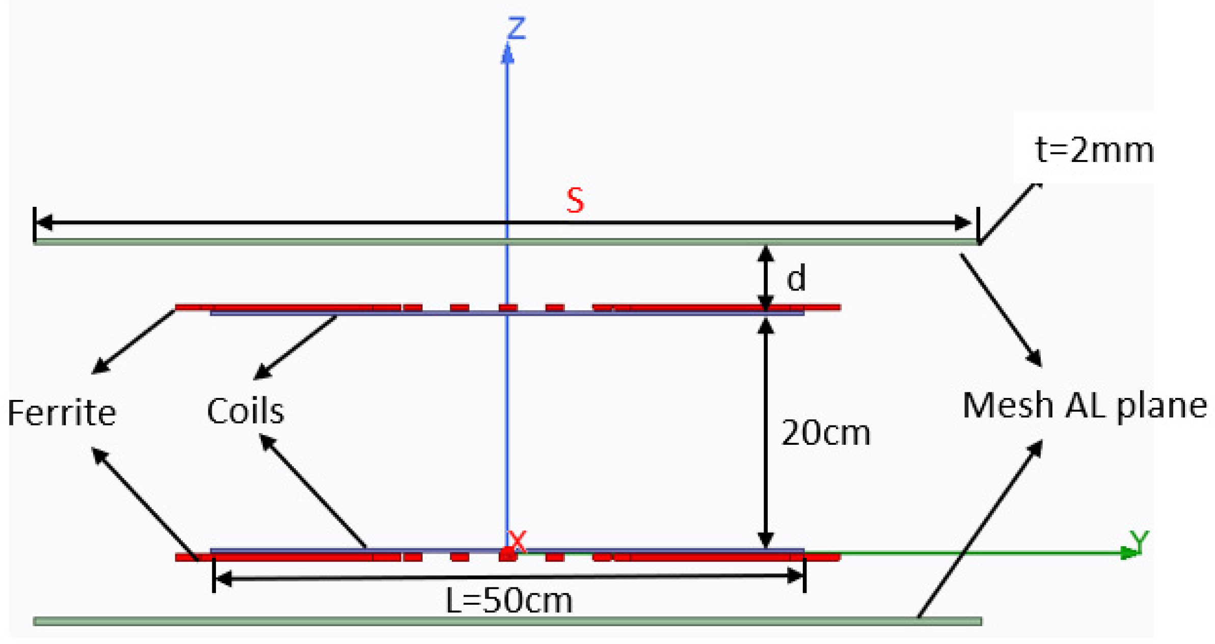
Firstly, the influence of different sizes of mesh aluminium plates is analysed. The schematic diagram of the structure is shown in Figure 7. It is assumed that the thickness of the mesh aluminium plate is t = 2 mm and the distance from the coil is d = 50 mm. Assuming that the coupling coils are all in a resonance state, when the size of the aluminium plate S increases from 50 cm to 100 cm, the changing relationship of the self-induction, resistance, coupling coefficient and transmission efficiency of the coupling coil is shown in Figure 8. k represents the coupling coefficient between the coils (the ratio of the mutual inductance between two coils to the product of their self-inductance). It can be seen from the figure that with the increase of the size of the aluminium plate, the influences of the transmitting coil and receiving coil of the reticulated aluminium plate with different array structures tend to be the same, that is, the inductance shows a downward trend, while the resistance changes slightly. The coupling coefficient and transmission efficiency of the system also decreases gradually with the increase of the size, mainly because the larger the mesh size of the aluminium plate, the obstruction effect on the coupling coil magnetic field will increase, thus affecting the mutual coupling between the transmitting coil and the receiving coil. However, when the size of the aluminium plate increases to 1.6 times of coil size (80 cm), the decreasing trend of transmission efficiency of the system gradually slows down. Compared with the 8 × 8 and 16 × 16 array mesh aluminium plate structures, the 4 × 4 mesh structure has the least influence on the transmission efficiency of the system. In conclusion, the size of the mesh of the aluminium plate has a significant influence on transmission performance, and the denser the mesh, the greater the influence on transmission efficiency, but when the size increases to a certain extent, the size of mesh has little influence on transmission efficiency.
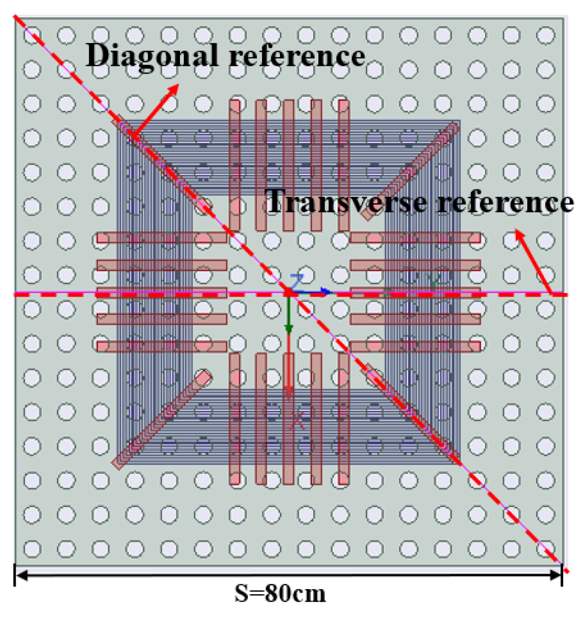
To further study the electromagnetic shielding effect of different array meshed aluminium plates on WPT systems, the magnetic field intensity of the receiver is simulated and analysed. Considering the symmetry of the coupling mechanism and the mesh aluminium plate, two reference lines are selected here: transverse and diagonal reference lines, as shown in Figure 9. The electromagnetic field intensity of transverse and diagonal reference lines can be obtained by simulation, which can be used to characterize the electromagnetic shielding effect of the meshed aluminium plate.
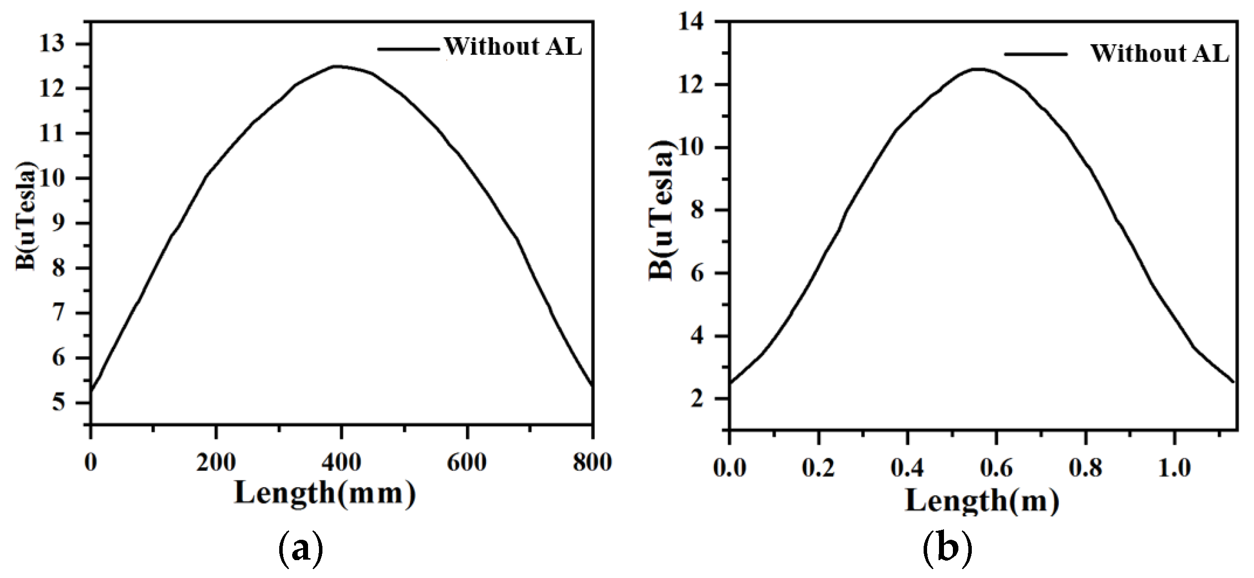
When the EVs’ wireless charging system is not loaded with mesh aluminium plate for electromagnetic shielding, simulation and comparative analysis are conducted on the magnetic fields of the transverse and diagonal reference lines at different heights. Here, S = 80 cm, and the magnetic induction intensity of the reference line at the receiving end varies with the length, as shown in Figure 10. If the current flowing into the coupling coil is 1 A, it can be found when the distance between the reference line and the coil is from 10 cm to 50 cm, the magnetic field intensity decreases sharply with the increase of the distance. When the height is 50 cm, the magnetic induction intensity on the reference line changes little with the length. In general, for the WPT systems without shielding, the magnetic induction intensity changes in a “peak shape”, the magnetic field in the middle is the largest, and the magnetic field on both sides is relatively small, because the coupling coil can be equivalent to a multi-turn coil, and according to the magnetic field superposition theorem, the magnetic field in the middle is the strongest.
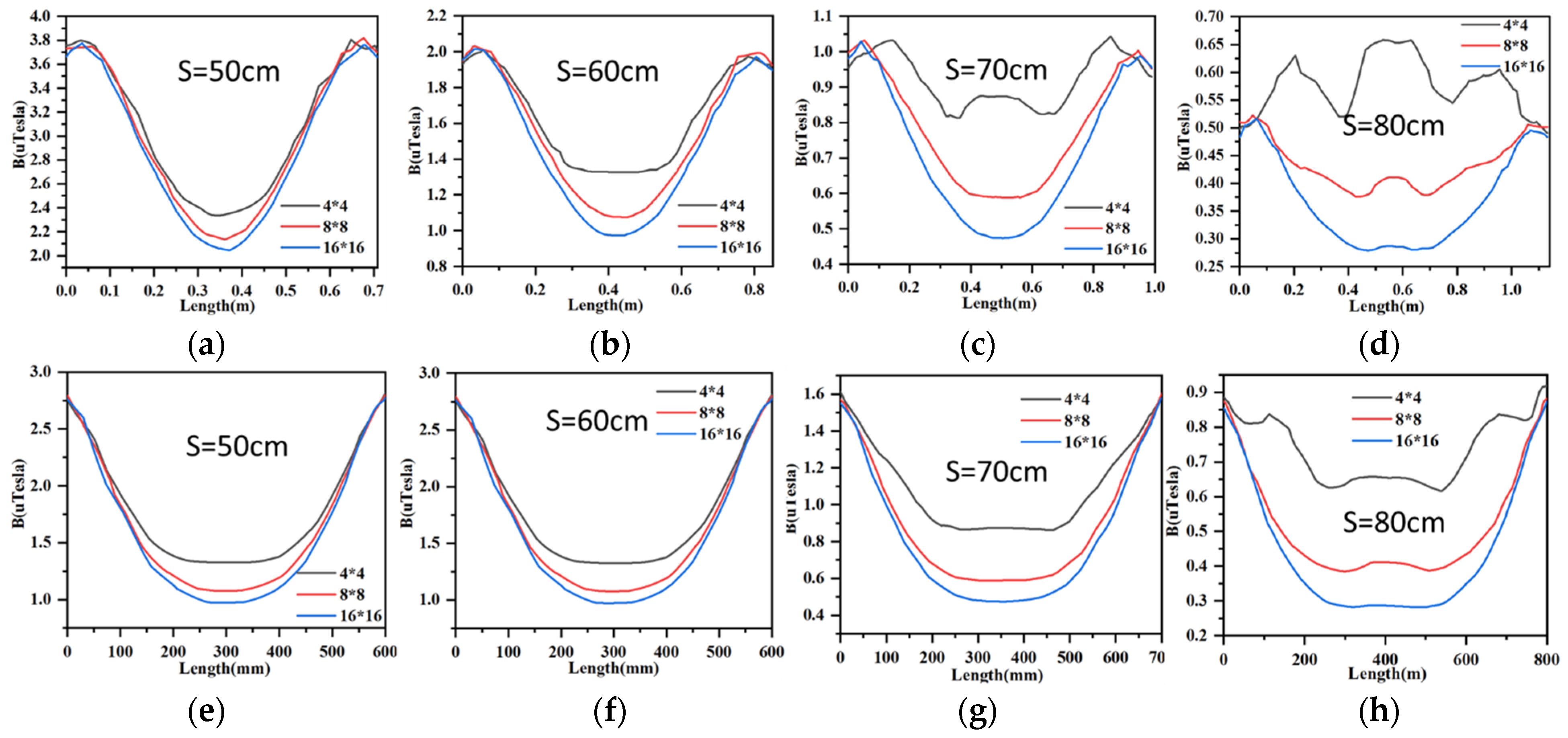
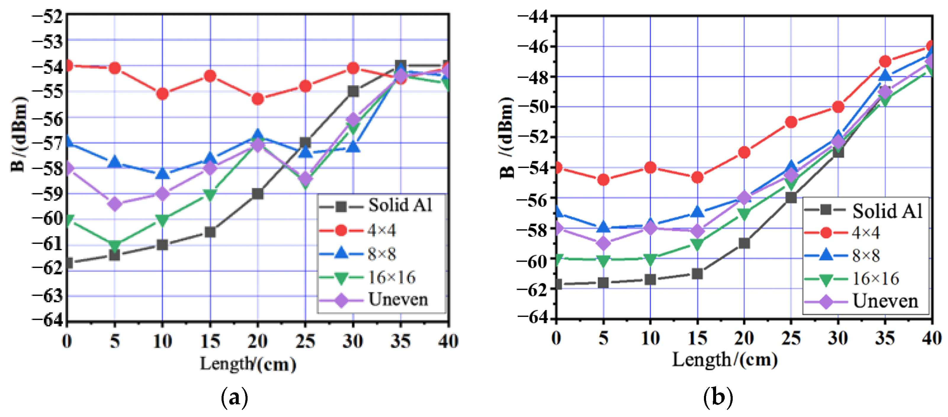
Figure 11 shows the variation of magnetic induction intensity of transverse and diagonal reference direction lines with the size of the meshed aluminium plate. It is assumed that the distance between the meshed aluminium plate and the coil is D = 50 mm, and the distance between the two reference lines and the meshed aluminium plate is 10 cm. In the actual electric vehicle wireless transmission system, the practicality and feasibility of the shielding body should be considered, and the size of the aluminium plate should not be too large. Therefore, when S changes from 50 cm to 80 cm, the change of magnetic field strength of the reference line is selected. As can be seen from the figure, compared with the unshielded body, the mesh aluminium plate can effectively reduce electromagnetic leakage. It is worth noting that the electromagnetic leakage at the centre of the reference line is effectively suppressed, and the surrounding magnetic field is also greatly reduced. The magnetic induction intensity is “sagging”, and the general trend is small in the middle and large on both sides. This is because of the presence of mesh aluminium plate, there will be an edge effect; that is, magnetic field lines will gather at the edge of the shielding layer, generating a strong electromagnetic field. With the increase of mesh aluminium plate size, the shielding effect is gradually better, and the edge effect is gradually weakened. When the mesh aluminium plate size is small, compared with the 4 × 4 mesh array structure, the electromagnetic shielding effect of 8 × 8 and 16 × 16 mesh structure tends to be the same. However, when the size of the meshed aluminium plate increases, due to the large mesh aperture of the 4 × 4 array structure, more magnetic field lines emanate from the mesh, resulting in the slow enhancement of the magnetic field at the centre. Compared with the 4 × 4, 8 × 8 structure, the 16 × 16 array structure has more dense mesh, the most serious reduction in efficiency, and the effect is like the aluminium plate. Therefore, the transmission performance of electric vehicle wireless transmission systems is also affected the most.
In conclusion, the size of the mesh aluminium plate has a great influence on the transmission performance of the wireless transmission system, but when the size of the mesh aluminium plate increases to a certain value, it almost has no influence on the transmission efficiency. Moreover, the larger the mesh aluminium plate size, the better the electromagnetic shielding effect, but at the same time, there is an edge effect, resulting in a strong magnetic field around the aluminium plate. For aluminium plates with different mesh structures, the denser the mesh, the better the shielding effect, but the greater the influence on the transmission performance of the system. In practical application, the large size of the aluminium plate not only affects the transmission performance of the system, but also increases the volume and weight of the shield, which brings challenges to the practical application of electric vehicle wireless transmission system. From the above analysis, it can be seen that the mesh aluminium plate with side length S = 80 cm can meet the demand of transmission efficiency. When the size continues to increase, the performance of the system remains basically unchanged, and it has a good shielding effect on electromagnetic leakage. Therefore, the mesh aluminium plate with a side length of 80 cm can be selected to better meet the needs of practical applications.
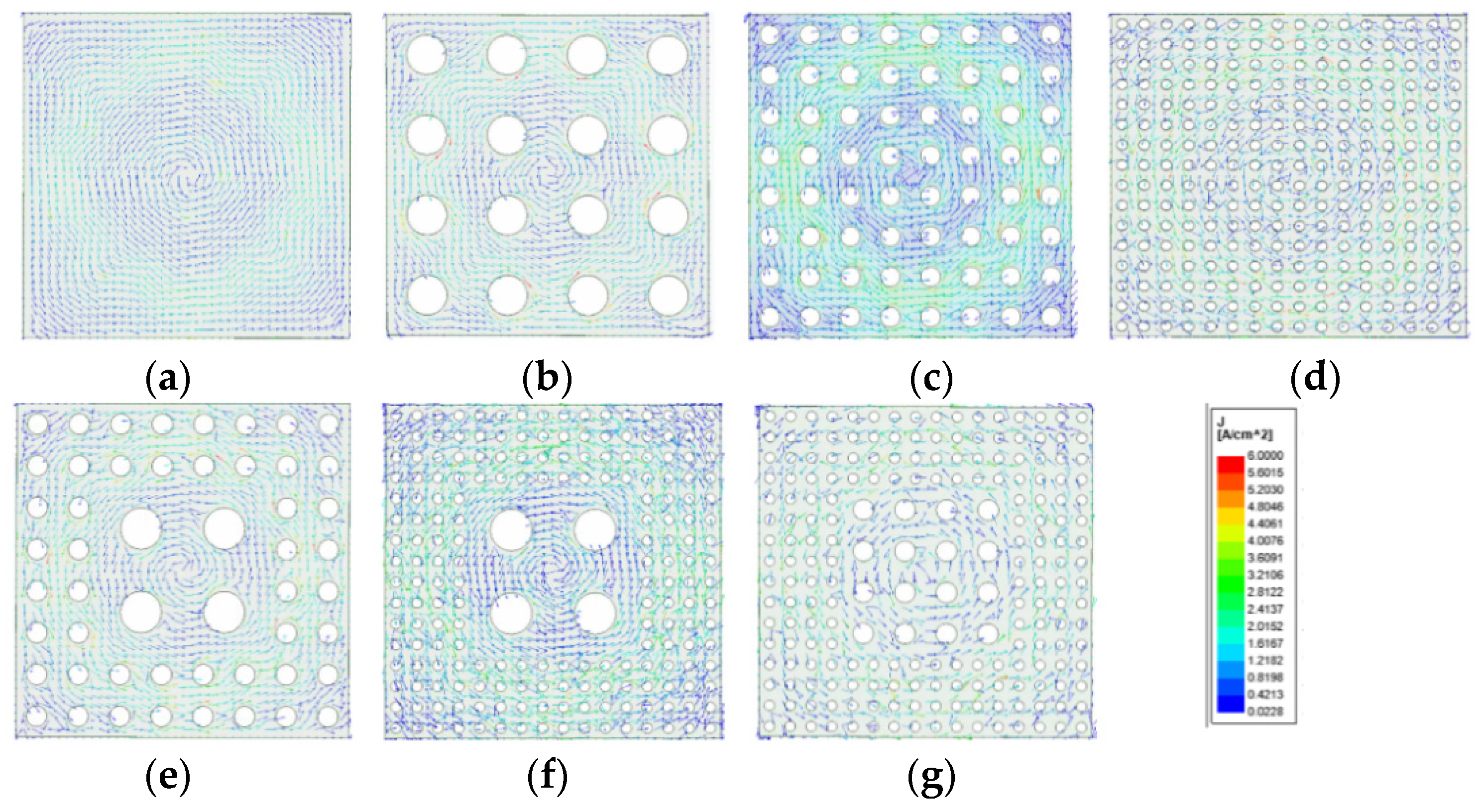
Figure 12 shows the current vector diagrams of different shielded aluminium plates. According to the above theoretical analysis, the changing magnetic field will induce the eddy current on the shielding aluminium plate, and the magnetic field generated by the eddy current lags 180° behind the original magnetic field, so it can inhibit the original magnetic field. It can be seen from the simulation current vector diagram of solid aluminium plate and mesh aluminium plate that the eddy current is mainly concentrated in an annular region. In this region, due to the presence of the mesh, the cross-sectional area of the loop is reduced, which leads to the increase of loop resistance and the decrease of induced current, and relatively weakens the shielding effect of the aluminium plate. By comparing the induced current vector diagrams of 4 × 4, 8 × 8 and 16 × 16, it can be found that the 4 × 4 mesh almost completely cuts off the main loop of the induced current, so the shielding effect of the aluminium plate with a 4 × 4 mesh structure is the least ideal. The 8 × 8 and 16 × 16 mesh structures weaken the eddy current in turn, and the shielding effect is gradually enhanced. The same phenomenon also exists for the non-uniform mesh aluminium plate. The magnetic field near the coil axis and away from the axis is affected by the central and peripheral mesh conditions of the aluminium plate, respectively. In terms of shielding effect, 4 × 4/8 × 8 (centre 4 × 4 edge 8 × 8 perforation) < 4 × 4/16 × 16 < 8 × 8/16 × 16, and all three are weaker than solid aluminium plate and 16 × 16 mesh structure.
A series of simulation studies were also carried out to analyze the impedance changes and transmission characteristics of different mesh arrays, as shown in Table 1. According to the results, the influence of composite mesh on electrical parameters and transmission characteristics is between the uniform mesh, and the change is small, which will not be described in detail here. Compared with the aluminium plate with a uniform mesh array structure, the aluminium plate with non-uniform mesh can achieve a good shielding effect of the electromagnetic field in the target area through mesh density design. In a word, the denser the mesh, the better the shielding effect of the aluminium plate. Through the unequal design of the mesh array, the electromagnetic shielding effect of the aluminium plate can be flexibly adjusted.
The guidelines issued and updated by the International Commission for Non-Ionizing Radiation Protection (ICNIRP) to limit exposure to time-varying electric and magnetic fields are aimed at the maximum magnetic induction intensity within a space. Therefore, the leakage field in the central area of the shield plate is far less than the standard if the leakage field around the shield meets the standard. Based on this situation, this article considers using a large mesh in the middle and a small mesh around it to weaken the eddy current in the central area of the aluminium plate without changing the maximum leakage magnetic induction. This design can reduce the impact on efficiency while taking into account shielding performance.

3.3. Effect of Plane Shape on System

The shape of the mesh is also one of the influencing factors. This paper simulates one square mesh and two circular meshes. One type of circular hole has the same area as the square hole, and the other type of circular hole has the same diameter as the side length of the square hole. The simulated magnetic induction intensity distribution curve is shown in Figure 13. The result shows that the equal diameter circle has the strongest shielding performance against the central magnetic field due to its smaller area. In the case of equal area, the effect of the square mesh is more in line with the design concept proposed in the previous section. Furthermore, compared to the area of the circular mesh, which cannot exceed 78.54% of the area of the aluminium plate (otherwise the aluminium plate will be broken into many small pieces), the area of the square mesh can reach close to 100%, which means the square mesh has a larger adjustment range.

3.4. The Final Design and Experiment

Figure 14 shows the mesh aluminium plates of four different array structures used in the experiment, whose sizes are the same as the simulation Settings. The side length of the mesh aluminium plate is set as S = 80 cm, and the thickness is set as t = 2 mm when aluminium plates with different structures are placed in the wireless transmission system of electric vehicles and the distance from the transmission coil is 5 cm. Figure 15 shows the EVs wireless charging experimental platform. The whole system is composed of the transmitting side (DC power supply, full-bridge inverter, signal generator), the resonant coupling mechanism (transmitting coil, receiving coil, primary and secondary side compensation capacitor) and the receiving side (rectifier, equivalent resistance load). The size of the coupling mechanism is consistent with the simulation settings. The transmission coils are square spiral structures, and the outermost edge length of the coils is 50 cm. The transmitting coil has 14 turns, the receiving coil has 13 turns, and the distance between the two coils is 20 cm. Ferrite material (PC40) is attached to the outside of the transmission coil to enhance the coupling strength between the two coils. Table 2 shows the experimental parameters of the charging system without an aluminium plate. These electrical parameters are measured by the benefit and impedance analyser (MICROTEST 6379). When the shielding aluminium plate is not added, the working frequency of the electric vehicle wireless transmission system is 85 kHz. It can be seen that the experimental results are basically consistent with the simulation results, and the resonant compensation capacitance is 21.3 nF.
When aluminium plates of different structures are loaded into the wireless transmission system of electric vehicles, the resonant frequency of the coil will change due to the change of inductance. By tuning the wireless transmission system, the system will always be in a resonant state. Figure 16 shows the comparison of measured and calculated transmission efficiency of electric vehicle wireless transmission systems under different aluminium plate structures. When the wireless transmission system is not shielded with an aluminium plate, the transmission efficiency is about 97.54%. It can be seen from the experimental results that when the system is loaded with a solid aluminium plate, the transmission efficiency of the system is less than 90%, while the mesh aluminium plate can reduce the impact on the transmission efficiency of the system, the efficiency is more than 90%. Among them, the 4 × 4 mesh aluminium plate has the least influence on the system. It should be noted that the influence of aluminium plate with non-uniform mesh on the transmission efficiency of the system is between uniform mesh, which is also consistent with the simulation analysis.
The transverse/diagonal magnetic field of the electric vehicle wireless transmission system is analyzed experimentally. It is assumed that the current of the receiving coil is always 1 A. Since the coupling mechanism is symmetrical, the magnetic fields on both sides of the coupling mechanism are equal to each other from the centre. Therefore, only measuring the magnetic field at one end can reflect the magnetic field suppression of the whole reference line. The magnetic field strength was measured by a spectrum analyzer and a near-field probe, which was 10 cm away from the receiving coil. The magnetic field distribution diagram is shown in Figure 17 when the system is not equipped with a shielded aluminium plate. It can be seen from the figure that when the system is not equipped with the shielding material, the magnetic field at the centre is the strongest, and the magnetic field weakens rapidly as the test point moves outward, which is also consistent with the magnetic field size trend of the simulation of the unshielded aluminium plate in the preceding chapter.
Figure 18 is the receiving end of lateral/diagonal direction magnetic field size change curve for loading different structural aluminium electric vehicle wireless power transmission system, in which the near-field probe distance shield aluminium plate is 5 cm. The figure shows that when the charging system load shielding aluminium plate and the test point moves outward, different structures of the aluminium plate’s magnetic field are increasing overall. This is because the current generated by the eddy current effect on the aluminium plate is mainly concentrated in the outer annular region, which is consistent with the simulation law of the upper magnetic field, and the magnetic field reaches the highest at the outermost part of the aluminium plate due to the edge effect. In general, a solid aluminium plate has the best electromagnetic suppression effect, but the advantage is not obvious compared with other mesh aluminium plates. Compared with the case without an aluminium plate, the maximum attenuation of the magnetic field at the centre point is 26 dB when the mesh aluminium plate is loaded. When the test point is close to the outside, the screen effect of the mesh aluminium plate is better than that of the solid aluminium plate. Compared with the mesh aluminium plate of different structures, it can be seen that the denser the mesh, the better the shielding effect, while the aluminium plate of the non-uniform mesh structure is between the uniform aluminium plate, which can be flexibly adjusted by changing the distribution of the mesh. It is worth mentioning that, as can be seen from Figure 18b, the diagonal direction reference line will pass through part of the mesh aluminium plate. Due to the influence of magnetic leakage, some magnetic fields will have high intensity and show a fluctuation state. The experimental results are also well demonstrated and consistent with the simulation analysis.

4. Conclusions

This paper analyses the influence of the metal shielding plate on the wireless charging system of electric vehicles through the equivalent coupling circuit theory. Then, the software was used to simulate the influence of meshes of different sizes and shapes on the performance of the shielding aluminium plate, and whether it can reduce the change of system parameters. Finally, a shielded aluminium plate with non-equal large square meshes was designed, and simulations and experiments were carried out. The results show that compared with the solid plate, the designed mesh plate increases the system efficiency by 1.3% while the maximum leakage magnetic field does not change, and the perforated form also greatly reduces the weight of the shielding plate. The design method of the non-equal large mesh aluminium plate proposed in this paper has a certain guiding significance for the electromagnetic shielding design of the electric vehicle wireless charging system.

Author Contributions

Conceptualization, K.W. and Z.Z.; formal analysis, K.W. and L.S.; investigation, Z.Z. and X.Z.; methodology, K.W.; supervision, L.S. and X.Z.; validation, K.W. and Z.Z.; writing—original draft, K.W. All authors have read and agreed to the published version of the manuscript.

Funding

This paper was supported by the science and technology project of State Grid Corporation of China. The Project name is research on accurate alignment and test technology of electric vehicle wireless power transfer systems based on intelligent perception. The project number is 5418-202040214A-0-0-00.

Conflicts of Interest

The authors declare no conflict of interest.

References

  1. Wang, Y.; Luan, T.H.; Su, Z.; Zhang, N.; Benslimane, A. A Secure and Efficient Wireless Charging Scheme for Electric Vehicles in Vehicular Energy Networks. IEEE Trans. Veh. Technol. 2022, 71, 1491–1508. [Google Scholar] [CrossRef]
  2. Nezamuddin, O.N.; Nicholas, C.L.; dos Santos, E.C. The Problem of Electric Vehicle Charging: State-of-the-Art and an Innovative Solution. IEEE Trans. Intell. Transp. Syst. 2021, 1–11. [Google Scholar] [CrossRef]
  3. Kadem, K.; Le Bihan, Y.; Bensetti, M.; Laboure, É.; Diet, A.; Debbou, M. Reduction of the shielding effect on the coupling factor of an EV WPT system. In Proceedings of the 2019 IEEE PELS Workshop on Emerging Technologies: Wireless Power Transfer (WoW), London, UK, 18–21 June 2019; Institute of Electrical and Electronics Engineers (IEEE): Piscataway, NJ, USA, 2019; pp. 21–24. [Google Scholar]
  4. Cruciani, S.; Campi, T.; Maradei, F.; Feliziani, M. Active Shielding Design for a Dynamic Wireless Power Transfer System. In Proceedings of the 2020 International Symposium on Electromagnetic Compatibility—EMC EUROPE, Rome, Italy, 23–25 September 2020; Institute of Electrical and Electronics Engineers (IEEE): Piscataway, NJ, USA, 2020. [Google Scholar]
  5. Li, J.; Yin, F.; Wang, L. Transmission efficiency of different shielding structures in wireless power transfer systems for electric vehicles. CSEE J. Power Energy Syst. 2021, 7, 1247–1255. [Google Scholar]
  6. Campi, T.; Cruciani, S.; Maradei, F.; Feliziani, M. Magnetic Field Mitigation by Multicoil Active Shielding in Electric Vehicles Equipped With Wireless Power Charging System. IEEE Trans. Electromagn. Compat. 2020, 62, 1398–1405. [Google Scholar] [CrossRef]
  7. Zhang, B.; Carlson, R.B.; Galigekere, V.P.; Onar, O.C.; Pries, J.L. Electromagnetic Shielding Design for 200 kW Stationary Wireless Charging of Light-Duty EV. In Proceedings of the IEEE Energy Conversion Congress and Exposition (ECCE), Detroit, MI, USA, 11–15 October 2020; pp. 5185–5192. [Google Scholar] [CrossRef]
  8. Xu, C.; Wang, S.; Guo, W. Research on Metal Material Shield Structure Applied to Wireless Charging System of Electric Vehicle. Electr. Autom. 2020. (In Chinese) [Google Scholar]
  9. Zhou, L.B.; Liang, D.F.; Wei-Jia, L.I.; Wang, Y.; Yuan, Y.L.; Wu, P. Magnetic Shielding Material for Wireless Charging. Magn. Mater. Devices 2019, 50, 57–63. [Google Scholar]
  10. Zhang, X.; Zhang, P.; Yang, Q.; Yuan, Z.; Su, H. Design and Analysis of Magnetic Shielding of Electric Vehicle Wireless Charging Coupling Mechanism Based on Finite Element Method. Trans. China Electrotechnol. Soc. 2016, 31, 71–79. [Google Scholar] [CrossRef]
  11. Zhao, H.; Liu, K.; Li, S.; Yang, F.; Cheng, S.; Eldeeb, H.H.; Kang, J.; Xu, G. Shielding Optimization of IPT System Based on Genetic Algorithm for Efficiency Promotion in EV Wireless Charging Applications. IEEE Trans. Ind. Appl. 2021, 58, 1190–1200. [Google Scholar] [CrossRef]
  12. Cui, H.; Zhong, W.; Li, H.; He, F.; Chen, M.; Xu, D. A study on the shielding for wireless charging systems of electric vehicles. In Proceedings of the 2018 IEEE Applied Power Electronics Conference and Exposition (APEC), San Antonio, TX, USA, 4–8 March 2018; Institute of Electrical and Electronics Engineers (IEEE): Piscataway, NJ, USA, 2018; pp. 1336–1343. [Google Scholar]
  13. Hariri, A.; El Hariri, M.; El Sayyed, A.; Mohammed, O.A. An Iterative Design Approach for Shielding of WPT Systems in Electric Vehicle Charging Applications. In Proceedings of the 2016 Vehicle Power & Propulsion Conference, Hangzhou, China, 17–20 October 2016; Institute of Electrical and Electronics Engineers (IEEE): Piscataway, NJ, USA, 2016. [Google Scholar]
  14. Kim, S.; Kim, H.; Kim, J.J.; Bae, B.; Kong, S.; Kim, J. Electromagnetic interference shielding effects in wireless power transfer using magnetic resonance coupling for board-to-board level interconnection. In Proceedings of the IEEE International Symposium on Electromagnetic Compatibility, Denver, CO, USA, 5–9 August 2013; Institute of Electrical and Electronics Engineers (IEEE): Piscataway, NJ, USA, 2013. [Google Scholar]
  15. Kim, S.; Jung, D.H.; Kim, J.J.; Kong, S.; Song, C.; Kim, J. Modeling of electromagnetic interference shielding materials in wireless power transfer for board-to-board level interconnections. In Proceedings of the 2014 IEEE Wireless Power Transfer Conference, Jeju, Korea, 8–9 May 2014; Institute of Electrical and Electronics Engineers (IEEE): Piscataway, NJ, USA, 2014. [Google Scholar]
  16. Kim, H.; Song, C.; Kim, J.; Jung, D.H.; Song, E.; Kim, S.; Kim, J. Design of Magnetic Shielding for Reduction of Magnetic Near Field from Wireless Battery Charging System for Electric Vehicle. In Proceedings of the IEEE International Symposium on Electromagnetic Compatibility, Gothenburg, Sweden, 1–4 September 2014; Institute of Electrical and Electronics Engineers (IEEE): Piscataway, NJ, USA, 2015; pp. 53–58. [Google Scholar]
  17. Miao, J.; Chang, H.; Zeng, H.; Tang, G. Research on Radiation and Shielding of Electric Vehicle Wireless Charging System. Electr. Appl. 2020, 39, 16–21. [Google Scholar]
Figure 1. Equivalent circuit of single coil with aluminium plate.
Energies 15 01546 g001
Figure 2. Schematic diagram of field circuit structure of electric vehicle wireless power transmission system loaded with shielded aluminium plates.
Energies 15 01546 g002
Figure 3. Equivalent circuit of wireless charging system with shielding plate.
Energies 15 01546 g003
Figure 4. The magnetic induction intensity of the non-meshed aluminium plate electromagnetic shielding.
Energies 15 01546 g004
Figure 5. Comparison of electromagnetic field distribution of wireless transmission systems with different mesh aluminium plates.
Energies 15 01546 g005
Figure 6. Magnetic field distribution of aluminium plate with different mesh array structure: (a) solid aluminium plate; (b) 4 × 4; (c) 8 × 8; (d) 16 × 16.
Energies 15 01546 g006
Figure 7. Schematic diagram of wireless transmission system for changing mesh aluminium plate size.
Energies 15 01546 g007
Figure 8. Influence of mesh aluminium plate size on impedance and transmission performance: (a) transmitting coil inductance; (b) transmitting coil resistance; (c) receiving coil inductance; (d) receiving coil resistance; (e) coupling coefficient; (f) transmission efficiency.
Energies 15 01546 g008
Figure 9. Schematic diagram of transverse and diagonal reference lines of the mesh aluminium plate in the wireless transmission system.
Energies 15 01546 g009
Figure 10. Magnetic induction intensity of shielding without aluminium plate: (a) transverse direction; (b) diagonal direction.
Energies 15 01546 g010
Figure 11. Magnetic induction intensity of mesh aluminium plate electromagnetic shielding: (a) 50 cm in transverse direction; (b) 60 cm in transverse direction; (c) 70 cm in transverse direction; (d) 80 cm in transverse direction; (e) 50 cm in diagonal direction; (f) 60 cm in diagonal direction; (g) 70 cm in diagonal direction; (h) The diagonal direction 80 cm.
Energies 15 01546 g011
Figure 12. Eddy current vector distribution on an aluminium plat: (a) Solid aluminium plate; (b) Aluminium plate with 4 × 4 mesh, (c) Aluminium plate with 8 × 8 mesh, (d) Aluminium plate with 16 × 16 mesh, (e) Center 4 × 4 edge 8 × 8 mesh, (f) Center 4 × 4 edge 16 × 16 mesh, (g) Center 8 × 8 edge 16 × 16 mesh.
Energies 15 01546 g012
Figure 13. Simulation of the magnetic induction intensity distribution curve in the case of circular and square meshes.
Energies 15 01546 g013
Figure 14. Physical picture of meshed aluminium plate, (a) 4 × 4, (b) 8 × 8, (c) 16 × 16, (d) non-uniform.
Energies 15 01546 g014
Figure 15. EVs wireless charging experimental platform.
Energies 15 01546 g015
Figure 16. Comparison of transmission efficiency of the system loaded with aluminium plates of different structures.
Energies 15 01546 g016
Figure 17. Magnetic field size without loading shielding aluminium plate, (a) transverse magnetic field, (b) diagonal magnetic field.
Energies 15 01546 g017
Figure 18. Magnetic field size without loading shielding aluminium plate, (a) transverse magnetic field, (b) diagonal magnetic field.
Energies 15 01546 g018
Table 1. System parameters without shielding plate and using four shielding plates.
Without4 × 4 Mesh8 × 8 Mesh16 × 16 MeshSolid
L1/μH185.94171.06170.08170.07169.55
R1/mΩ59.2760.43766.92867.17571.01
L2/μH169.87155.51154.67154.68153.95
R2/mΩ53.2754.95758.76958.16159.27
M12/μH39.2728.4427.9727.9227.70
Table 2. System electrical parameters.
Ls/μHLr/μHM/μHRs/mΩRr/mΩ
Simulation185.94169.8737.52170.58161.15
Measured180.44165.5536.29176.12165.24
Publisher’s Note: MDPI stays neutral with regard to jurisdictional claims in published maps and institutional affiliations.

