Abstract
Due to the effects of splitting frequency and cross coupling, the resonant frequency of the WPT system usually deviates from the given frequency band, and the system operating at the given frequency band suffers a very low output power. Ensuring that electric vehicle wireless power transfer (EV-WPT) systems operate at a resonant state is the prerequisite for efficient energy transfer. For this purpose, a novel design method by manipulating the eigenstate parameters is proposed in this paper. The proposed system can make a EV-WPT system with arbitrary coil successfully to resonate at any given bands, not just a single band. Therefore, the method designed in this article cannot only eliminate the problem of low power caused by frequency deviation, but also realize the application requirements of multiple frequency bands. Firstly, this article establishes an accurate state space model of an n-coil fully coupled EV-WPT system, and after that, the analytical current response on each circuit is derived. Based on that, a detailed frequency spectrum analysis is presented, along with several essential spectrum parameters’ derivations, including center frequencies and bandwidths. Then, with the center frequency and bandwidth as the design indexes, a novel methodology of designing to make EV-WPT systems achieve resonant-state at arbitrary given bands is derived. Finally, simulation and experimental verification are carried out. Simulation and experimental results show that whether it is a single-band or multi-band system, the accuracy of the value under designed resonant frequency is less than 0.01, which can effectively eliminate the frequency deviation phenomenon and obtain the maximum power output at the given frequency band.
1. Introduction
Magnetic coupling wireless power transfer (MC-WPT) system transfer energy from power sources to electric loads by coupled magnetic field. Due to the electric isolation between the sources and loads, this technology has advantages such as enough flexibility, full reliability, and high security. New research hotspots have emerged since the inspiring work in which researchers transferred 60 W power to a lamp over a distance of 2 m in 2007 [1,2]. Considerable research of this technology developed over the past decades has paved the way towards practical applications of this technology, such as electric vehicles (EV) [3,4], consumer electronics [5,6], and so on. With the development of MC-WPT technology and the expansion of the application field, more complicated multi-coils MC-WPT systems, such as multi-transmitter systems [7,8], multi-receiver systems [8,9], and multi-repeater systems [10,11,12], has received great attention in recent years.
For an electric vehicle wireless power transfer (EV-WPT) system, multiple industry consortia are developing corresponding standards for the components of EV-WPT systems, including the standard for operating frequency [13,14,15]. It is well known that the overwhelming majority of EV-WPT system designs are on the basis of the “resonant coupling principle” proposed in paper [1], which aims to make the natural frequency of each oscillating circuit in the system and the operating frequency of the system equal to the given frequency for the maximum power transfer [16,17,18]. However, since the phenomenon termed as “frequency splitting”, there are multiple resonant points deviated from the designed circuits’ natural frequency. Hence, the system operating at the given frequency suffers a much lower energy efficiency [19,20,21]. This ensures that the system operating at resonant state is a key point to efficient power transfer [22].
At present, frequency tracking [23], adding impedance matching network [24,25] and adjusting the coupling strength [19,20] are the most common methods used to compensate the energy efficiency against the frequency splitting. However, frequency tracking makes the system capable of operating at a varying optimal frequency, but not a given frequency. The essence of adding an impedance matching network and adjusting the coupling strength is adjusting some inner parameters to eliminate frequency splitting phenomenon. Since the number and position of the resonant points are determined by several parameters such as self-inductances, capacitors and resistances, the specific impedance matching network or adjusting method of coupling strength is different from system to system, and then they are difficult to apply in multi-coil EV-WPT systems. So far, there are no systematic design methods for the EV-WPT system to achieve resonant-state at a given band, which is a bottleneck problem that needs to be solved.
In addition, the multi-band EV-WPT systems have been receiving greater attention in recent years. The multi-band EV-WPT systems can not only satisfy multiple frequency standards, but also can transfer power and data simultaneously. The traditional multi-band EV-WPT systems are usually achieved by subjoining extra LC circuits [26,27] or extra coils [28,29,30]. The LC circuits or coils must increase with the increase of bands, which will make the system become complicated. Since the traditional design process of multi-band EV-WPT systems is based on the actual characteristic equation of maximum power transfer points versus the operating frequency, it is only suitable for simple EV-WPT systems with a few bands, but not for complicated multi-coil or multi-band EV-WPT systems.
In this paper, a novel design method by manipulating the eigen parameters is proposed in this paper. The proposed system can design an arbitrary coil EV-WPT system to resonate at arbitrary given bands, thereby not only eliminating the problem of low power caused by frequency deviation, but also realizing the application requirements of multiple frequency bands. The proposed method in this paper does not have to add any extra LC circuits or coils, and it suits arbitrary coil EV-WPT systems with arbitrary given bands (no more than the coils). Moreover, unlike the traditional design method of EV-WPT systems, in which the design indexes usually only consider the center positions of bands, here, the indexes of the proposed method include center frequency and bandwidth. Since the purpose of this paper is to design lumped parameters, not geometric parameters, there is no in-depth discussion on coil geometric parameters, voltage and load characteristic.
The arrangement of this paper is as follows: In Section 2, the state-space model of a general n-coil fully-coupled EV-WPT system with any number of transmitters, repeaters and receivers is established, and the current response on each circuit is derived at the same time. Based on that, the analytical expression of frequency spectrum parameters, including center frequencies and corresponding bandwidths, is deduced. In Section 3, the detailed design process with the center frequencies and bandwidths as the design indexes is presented, and then a systematic design criterion which suits designing arbitrary coil EV-WPT systems to resonate at arbitrary given bands is derived. According to the derived design criteria, a practical two-coil EV-WPT system with dual-band and single band is designed in Section 4. Finally, in Section 5, this article validates the proposed design method by building prototypes and tested it.
2. Theoretical Analysis
2.1. The Necessary Concepts
Before the theoretical analysis, several essential concepts related to the frequency spectrum of EV-WPT systems need to be clarified:
- Frequency spectrum curve: Frequency spectrum curve is the curve of output power versus the operating frequency, which usually is a multi-peak curve.
- Band: The frequency range when the current amplitude is reduced to 0.707 times the maximum current amplitude (the power is reduced to the half of the maximum output power), referred to as the band.
- Center frequency: The frequency of the peak is termed as the center frequency of the band.
- Multi-band system: Multi-band system means that the frequency spectrum of the system is a multi-peak curve. The number of peaks equal to the number of bands. Single-band system indicates that the frequency spectrum curve is a single-peak curve, dual-band system indicates that the frequency spectrum curve is a dual-peak curve, and tri-band system indicates that the frequency spectrum curve is a tri-peak curve.
- Cut-off frequencies: the frequencies at which the current amplitudes equal to 0.707 times the maximum current amplitude in a band term as the cut-off frequencies of the band. In a band, there are usually two half-power frequencies, one of which is greater than the center frequency, and the other is less than the center frequency.
- Bandwidth: the frequency range of the two cut-off frequencies is termed as the bandwidth of the band.
2.2. System Modeling
Figure 1 shows the equivalent circuit diagram of an n-coil fully coupled EV-WPT system with arbitrary number of transmitters, repeaters and receivers. The system consists of n coils and each of these is connected with a capacitor in series, resulting in forming an oscillating circuit.
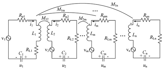
Figure 1.
The equivalent circuit diagram of a general n-coil fully coupled EV-WPT system.
In Figure 1, the subscript m represents the parameters in the m-th oscillating circuit (m = 1, 2, …, n). Rpm and Lm represent the equivalent series internal resistance (ESR) and self-inductance of the m-th coil respectively, Mmr is defined as the mutual inductance between the m-th coil and r-th coil (m ≠ r and Mmr = Mrm). Cm and um stand for the compensating capacitor and corresponding capacitor voltage of the m-th circuit. vm is the supply voltage and RLm is the load’s resistance of the m-th oscillating circuit, respectively. It must be noticed that vm and RLm cannot exist simultaneously. The role of the coil varies with the values of vm and RLm. The role of the coil varies with the values vm and RLm, as shown in Table 1.

Table 1.
The role of coils.
For mathematic analysis, assume that the power is a sinusoidal power supply voltage with an angular frequency of ω. Based on the Kirchhoff’s voltage law (KVL), the mathematic model of the system in Figure 1 can be established as
where Rm = Rpm + RLm (m ≠ n) and Rm = Rpm + RLm (m = n).
Let , and be the supply voltage vector, current vector and voltage vector for capacitor in the system illustrated above, respectively. Moreover, and are defined as the state vector and input vector of the system respectively; the model established in Equation (1) can be equivalent to the new formula as
where
stands for order zero matrix and is expressed as a unit matrix. L, C and R are the inductance matrix, capacitor matrix and resistance matrix of the system, which are given by
Equation (2) refers to a state space model. From Equation (2), the system matrix (S) can be derived as
2.3. Frequency Spectrum Analysis
According to [21], we can find out that there are at most n bands in an n-coil EV-WPT systems. If the number of bands is less than the number of coils in a EV-WPT system, it indicates that in the system exists a band overlap phenomenon. In general, for an actual physical system, even if the center frequencies are very close, the overlapping bands do not completely coincide because the bandwidths and peak heights are difficult to be equal completely at the same time. In other words, the system matrix of an actual physical system usually does not have the exact same eigenvalues and it can be normalized to a diagonal matrix. In this case, the current response im in the overlapping bands is superimposed by multiple vectors with different amplitudes and phases [21], and then the bandwidths of the overlapping bands are difficult to determine.
Aiming to quickly and accurately determine the bandwidths of bands and simplify the design process, in this paper, the overlapping bands are designed to be coincident completely and the non-overlapping bands are designed to be separated from each other. The existence of completely overlapping bands indicates that the system matrix has identical eigenvalues. In this case, the system matrix cannot be normalized to a diagonal matrix but to a Jordan matrix. Supposing that there are k different eigenvalues labeled as , and the multiplicity of eigenvalue is , then we can get that . On the basis of the practical system’s physical properties, the real part of eigenvalue is a negative number with a small absolute value [31]. Then and can be written as two conjugate complex numbers and , where and are positive number, moreover, is ordinarily pretty small.
Under this circumstance, according to the matrix theory, we can get that there are two non-singular matrixes and , which makes . The operator represents the generation of an diagonal matrix with the elements in the parentheses as the diagonal elements, and are conjugate complex matrix and is a Jordan matrix as shown in Equation (6).
According to , the state space model in Equation (2) can be equivalent to the new formula as
where and . According to , and the relationship between current vector and capacitor voltage current (), the current response on the m-th circuit (im) can be derived as
where
The derivation process of im in Equation (8) is given in Appendix A. The operator represent the imaginary part of the variable value, and is a plural as shown in Equation (A11) in the Appendix A. Equation (8) revealed that the amplitude of current is equal to the modulus of plural , that is . Meanwhile, from Equation (9) we can know that plural is superimposed by the k vectors and the amplitude of can be deduced as
will achieve the maximum value while the operating angular frequency ω equals to (), i.e.,
Since is generally pretty small, will be pretty large. In addition, since the overlapping bands are designed to be coincident completely and non-overlapping bands are designed to be separated from each other, that is, the k different eigenvalues () are far apart from each other, hence will be much larger than other items (j = 1, 2, …, k and j ≠ q) when the operating angular frequency ω is close to . In this case, can be approximate as
The analysis indicates that there are k bands in the system, whose center angular frequencies are , , …, . The plural in the q-th band can be approximated as . From Equation (10) we can obtain that the amplitude of versus the operating angular frequency ω is an unimodal curve, which can be roughly plotted as
In Figure 2, the points a and b are half-power points. On the basis of the definition of half-power point as elucidated in Section 2.1, we have
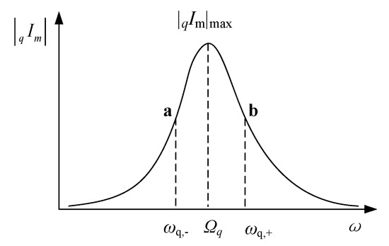
Figure 2.
versus the operating angular frequency ω.
According to Equations (10), (11) and (13), the frequencies of the two half-power points can be derived as shown in Equation (14). The derivation process is given in Appendix B.
Then the bandwidth Bq can be deduced as
Then we can get that, for a EV-WPT system with k different and separate eigenvalues , there are k-bands in the system, whose center angular frequency and corresponding bandwidth of the q-th band can be expressed as
3. Method to Design of Multi-Band EV-WPT Systems
It is well known that the center angular frequency and the bandwidth are two key indexes of frequency band. On the basis of the analysis in Section 2, we can know that the number of bands as well as the corresponding center frequencies and bandwidths of a EV-WPT system are determined by the values under eigenstate of the system matrix. Therefore, in turn, suitable eigenvalues can be determined according to the given center frequencies and bandwidths.
Supposing that k-band is required in an n-coil EV-WPT system and the required center frequencies and corresponding bandwidths are and respectively (k ≤ n). On the basis of the analysis in Section 2 we can be aware of that k bands indicate that there are k different eigenvalues of the system matrix (). Supposing that the multiplicity of the eigenvalue is , which can be determined by the designer on the premise of . In this case, according to the given center angular frequency (ωo,q) and it’s homologous bandwidth (Bq) of the q-th band, the suitable eigenvalues and can be quickly obtained as shown in Equation (17) by using Equation (16).
By using Equation (17), all eigenvalues satisfying the performance requirements can be quickly and accurately determined. Then the next step is to design the system parameters so that the eigenvalues of the system matrix equals to the expected values as shown in Equation (17).
According to the derived k different eigenvalues that are as shown in Equation (17), the expected characteristic formula which satisfy the performance requirements can be obtained as
In addition, on the basis of the definition of eigenvalues, we have
Substituting Equation (5) into Equation (19), we can get that
Evaluating Equation (20) by block matrices, we can get
Replacing the inductance matrix L, capacitor matrix C and resistance matrix R into Equation (21), the characteristic formula of the system can be deduced as
By comparing Equation (18) with Equation (22), we have
From Equation (23), the suitable system parameters that satisfy the performance requirements can be quickly and accurately determined.
According to the analysis referred above, the design criteria of multi-band EV-WPT systems can be summarized as
- S1.
- Determining the number of coils (n), inductance matrix L, capacitor matrix C and resistance matrix R according to the practical application, where the parameters need to be designed are represented by corresponding symbols as shown in Figure 1.
- S2.
- According to the application requirement, determining the number of bands (k) and corresponding center frequencies and bandwidths .
- S3.
- Determining the multiplicity of the q-th band. The value of rq is freely determined by the designer, but it need to satisfy .
- S4.
- Determining the expected eigenvalues ( and ) of the q-th band by using
- S5.
- Calculating the expected characteristic equation by using
- S6.
- Substituting matrix L, C and R into , the actual characteristic formula of the system can be calculated as
- S7.
- Then the parameters in expected system can be defined by using
4. Practical System Design
In Section 3, the design method for EV-WPT systems to achieve the state of resonance at given frequencies is proposed, which is suitable for arbitrary numbers of coils EV-WPT systems with arbitrary number of resonant points (no more than the coils). Aiming to verify the method proposed above, designing examples of tri-coil EV-WPT systems are illustrated in this Section.
4.1. The Nonlinear Programming Model of Tri-Coil EV-WPT Systems
According to the above analysis, we can obtain that a tri-coil EV-WPT system can be designed as the system with a single given resonant point, two given resonant points, or three given resonant points. No matter the system with how many resonant points, the design steps are the same expected for seeking the expected eigenvalues.
Supposing that the expected eigenvalues of system matrix of the tri-coil EV-WPT systems which determined by practical performance requirements are , , and , , . Substituting the expected eigenvalues into Equation (18), the characteristic equation of the system can be derived as
where
For tri-coil EV-WPT systems, the inductance matrix L, capacitor matrix C and resistance matrix R can be expressed as
Substituting Equation (30) into , the practical characteristic equation of two-coil EV-WPT systems can be established as
where
According to Equations (29) and (32), the nonlinear equation of tri-coil EV-WPT systems can be established by
The nonlinear equation of tri-coil EV-WPT systems in Equation (33) is too complex to be solved precisely. Then, the nonlinear equation of the tri-coil EV-WPT systems can be converted into
The self-inductances L1, L2, L3 and corresponding inner resistance Rp1, Rp2, Rp3 are coil dependent and can be predetermined. In the set of examples, the self-inductance L1, L2 and L3 are fixed at 57 μH and the inner resistance Rp1, Rp2 and Rp3 are fixed at 0.13 Ω. In addition, for tri-coil EV-WPT system with given coils, if the mutual inductance M12 and M23 are determined, then the mutual inductance M13 is fixed. All compensation capacitors are usually set to be equal in the actual systems, that is C1 = C2 = C3 = C. Then, the nonlinear programming model of the EV-WPT system with tri-coil can be established as
There are also four parameters waiting for the setting of the system: compensating capacitor C, mutual inductance M12, M23 and load resistance RL, which are able to be determined accurately by using Equations (32) and (35).
4.2. Parameter Design
In the set of examples, the self-inductance L1, L2 and L3 are fixed at 57 μH, and the inner resistance Rp1, Rp2 and Rp3 are fixed at 0.13 Ω. A tri-coil EV-WPT system can be designed as a single-band system, a dual-band system, or a tri-band system. This is providing that, on the basis of the actual requirement, the given center frequency and its corresponding bandwidth of the three systems are given, as shown in Table 2.
Table 2.
The given spectrum parameters.
Substituting the given parameters and given spectrum parameters shown in Table 2 into Equation (17) to Equation (35), the nonlinear model of the single-band system, dual-band system and tri-band system can be obtained. Solving these nonlinear models with the help of the genetic algorithm in Matlab software, the expected electric parameters of the systems can be determined as shown in Equation (36).
5. Experimental Verification
5.1. Experimental Setup
A practical EV-WPT system with three coils is established as shown in Figure 3 to verify the design method proposed in this article. The schematic diagram of the circuit of the system is shown in Figure 4, where an H-bridge consisting of four MOSFETs is used as the voltage source. Meanwhile, it acts as the transmitter which is coupled to the intermediate coil. The intermediate coil serves as a repeater, and the right coil is the receiver with a load. The geometric parameters of the three coils are set to be equal to the value listed in Table 3. In addition, the coils are aligned to the coil centers r = 0 along the z-axis. The measured self-inductances of the three coils are 57 μH and the inner resistances of the three coils are 0.13 Ω depending on a LCR digital electric bridge.
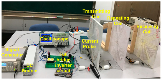
Figure 3.
The layout of the experimental setup.
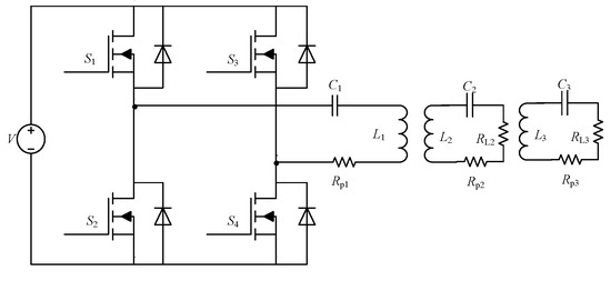
Figure 4.
Circuit schematic of the practical system.
Table 3.
The Geometric Parameters of the Practical Coils.
5.2. Practical Measurements
In the first set of experiments, the compensating capacitor C1, C2 and C3 are fixed at 22 nF and the load resistance RL = 20 Ω. The transfer distance d12 = 0.29 m and d23 = 0.16 m. For the given transmission distance, the mutual inductance M12, M23 and M13 are 3.34, 9.94 and 1.28 µH, which are pretty close to the optimal values of the single-band system as calculated in Equation (36). Meanwhile, simulation with the measured electric parameters are conducted. The supply voltage is adjusted at 8 V. And the operating frequency changes from 100 kHz to 200 kHz with a interval of 1 kHz. The power simulated and measured versus the operating frequency is plotted as shown in Figure 5a.
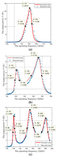
Figure 5.
The simulated and measured power versus the operating frequency of the tri-coil systems. (a) single-band system (k = 1). (b) dual-band system (k = 2). (c) Three-band system (k = 3).
In the second set of experiments, the compensating capacitor C1, C2 and C3 are fixed at 33 nF and the load resistance RL = 20 Ω. The transfer distance d12 = 0.1 m and d23 = 0.09 m. For the given transmission distance, the mutual inductance M12, M23 and M13 are 18.39, 20.42 and 7.56 µH, which are pretty close to the optimal values of the dual-band system as calculated in Equation (36). Similarly, simulations with the measured electric parameters are conducted. The supply voltage is fixed at 8 V. And the operating frequency changes from 100 kHz to 200 kHz with a interval of 1 kHz. The power simulated and measured versus the operating frequency is plotted as shown in Figure 5b.
In the third set of experiments, the compensating capacitors C1, C2 and C3 are fixed at 27 nF, and the load resistance RL = 10 Ω. The transfer distance d12 = 0.08 m and d23 = 0.07 m. For the given distance of energy transmission, the mutual inductance M12, M23 and M13 are 22.7, 25.3 and 10.9 µH, which closes the optimal values of the three-band system as calculated in Equation (36). Meanwhile, simulations with the measured electric parameters are conducted. The supply voltage is fixed at 8 V. And the operating frequency changes from 100 kHz to 200 kHz with a interval of 1 kHz. The power simulated and measured versus the operating frequency is plotted as shown in Figure 5c.
As indicated in Figure 5a, only one band emerges in the system, whose measured center frequency is 150 kHz and its corresponding bandwidth is about 10 kHz. The measured results fully satisfy the required performance indexes, illustrating that the design method proposed in this article is effective and accurate. In Figure 5b, there are two bands, whose measured center frequencies are about 101 kHz and 151 kHz, and the corresponding measured bandwidth are about 10 kHz and 24 kHz, respectively. In Figure 5c, there are three bands, whose measured center frequencies are about 100 kHz, 150 kHz and 200 kHz, and the respective corresponding measured bandwidth are about 5 kHz, 20 kHz and 15 kHz. The performance indexes are pretty close to the given values, which indicates that the proposed method is effective and accurate. In Figure 5, there are some deviations between the simulated value and measured value, which mainly caused by the deviation between the practical value and optimal value of the electrical parameters.
6. Conclusions
Multi-band EV-WPT technology is one of the important research trends of EV-WPT technology. In this paper, a novel generalized design method of multi-band EV-WPT systems is proposed by employing and utilizing frequency splitting. The design theory and design criteria of multi-band multi-coil EV-WPT systems are presented and explained, and have been verified by practical prototypes. Compared to the traditional design methods, the method proposed in this paper has the following advantages:
- The design indexes of the method proposed in this article include not only the center frequencies of the bands, but also the bandwidths.
- The proposed method does not have to add any extra LC branch circuits or extra coils.
- The proposed method suits for arbitrary coil EV-WPT systems with an arbitrary number of bands (no more than the coils), including a multi-coil EV-WPT system with a single given band (without frequency splitting phenomenon).
Author Contributions
Conceptualization, Q.Y.; Data curation, Y.X. and C.W.; Formal analysis, Y.X.; Methodology, Y.Y., C.W., Y.J. and Z.L.; Software, Y.Y.; Validation, Q.Y.; Writing—original draft, Y.Y., Y.J. and Z.L.; Writing—review & editing, Y.J. and Z.L. All authors have read and agreed to the published version of the manuscript.
Funding
This research received no external funding.
Conflicts of Interest
The authors declare no conflict of interest.
Appendix A
Derivation of the Current Response Is Shown in Equation (8). For mathematic analysis, assuming that the power is a sinusoidal power supply voltage with an angular frequency of ω. Then, the supply voltage can be rewritten as , where the operator represents the amplitude of the variable and stand for the imaginary part of the variable, i.e., . Under these circumstances, the supply voltage vector and the capacitor voltage vector of the system can be expressed as and respectively, where , and , (m = 1, 2, …, n). According to , , and , the vectors and can be obtained as and , where and . Substituting and into , yields
Substituting into Equation (A1), we have
Matrixes , and can be rewritten as block matrixes as shown in Equations (A3)–(A5), respectively.
Evaluating (A2) in terms of block matrixes as shown in Equations (A3)–(A5), the vector can be derived as
According to the definition of Jordan matrix , can be calculated as
By simultaneously solving Equations (A6) and (A7) and , the current vector of the system can be defined as , where
where . Then the current response on the m-th circuit can be derived as , where
Substituting and into Equation (A9) we can get that
where
Appendix B
The Derivation of the Half Power Point Frequency Shown in Equation (14). According to Equations (10) and (12), we can get the current amplitude of im in the q-th band to be deduced as
Then, according to , we have
Generally speaking, the angular frequencies of the half-power points of the q-th band are close to the center angular frequency . In this case, on the basis of Equation (A11), we can get that . Substituting into Equation (A13), we have
References
- Kurs, A.; Karalis, A.; Moffatt, R.; Joannopoulos, J.D.; Fisher, P.; Soljacic, M. Wireless power transfer via strongly coupled magnetic resonances. Science 2007, 317, 83–86. [Google Scholar] [CrossRef] [PubMed] [Green Version]
- Zhang, Z.; Pang, H.; Georgiadis, A.; Cecati, C. Wireless power transfer—An overview. IEEE Trans. Ind. Electron. 2019, 66, 1044–1058. [Google Scholar] [CrossRef]
- Mahesh, A.; Chokkalingam, B.; Mihet-Popa, L. Inductive wireless power transfer charging for electric vehicles—A review. IEEE Access 2021, 9, 137667–137713. [Google Scholar] [CrossRef]
- Jiang, Y.; Wang, L.; Wang, Y.; Liu, J.; Wu, M.; Ning, G. Analysis, design, and implementation of WPT system for EV’s battery charging based on optimal operation frequency range. IEEE Trans. Power Electron. 2019, 34, 6890–6905. [Google Scholar] [CrossRef]
- Chen, J.; Li, S.; Chen, S.; He, S.; Shi, Z. Q-Charge: A quadcopter-based wireless charging platform for large-scale sensing applications. IEEE Netw. 2017, 31, 56–61. [Google Scholar] [CrossRef]
- Zhou, J.; Zhang, B.; Xiao, W.; Qiu, D.; Chen, Y. Nonlinear Parity-Time-Symmetric model for constant efficiency wireless power transfer: Application to a Drone-in-Flight wireless charging platform. IEEE Trans. Ind. Electron. 2019, 66, 4097–4107. [Google Scholar] [CrossRef]
- Johari, R.; Krogmeier, J.V.; Love, D.J. Analysis and practical considerations in implementing multiple transmitters for wireless power transfer via coupled magnetic resonance. IEEE Trans. Ind. Electron. 2014, 61, 1774–1783. [Google Scholar] [CrossRef]
- Ahn, D.; Hong, S. Effect of coupling between multiple transmitters or multiple receivers on wireless power transfer. IEEE Trans. Ind. Electron. 2013, 60, 2602–2613. [Google Scholar] [CrossRef]
- Minh, Q.N.; Chou, Y.; Plesa, D.; Rao, S.; Chiao, J. Multiple-inputs and multiple-outputs wireless power combining and delivering systems. IEEE Trans. Power Electron. 2015, 30, 6254–6263. [Google Scholar] [CrossRef]
- Fu, M.; Zhang, T.; Zhu, X.; Luk, P.C.; Ma, C. Compensation of cross coupling in multiple-receiver wireless power transfer systems. IEEE Trans. Ind. Inform. 2016, 12, 474–482. [Google Scholar] [CrossRef]
- Yue, S.; Xia, J.; Tang, C.; Xiang, L. Path optimization for wireless power transfer networks with cellular genetic algorithm. J. Xi’an Jiao Tong Univ. 2017, 51, 30–36. [Google Scholar] [CrossRef]
- Zhao, Z.; Sun, Y.; Hu, A.; Dai, X.; Tang, C. Energy link optimization in a wireless power transfer grid under energy autonomy based on the improved genetic algorithm. Energies 2016, 9, 682. [Google Scholar] [CrossRef] [Green Version]
- BSS Standard A4WP-S-0001 v1.2; A4WP Wireless Power Transfer System Baseline System Specification. A4WP: Fremont, CA, USA, 2014.
- Wireless Power Consortium. System Description Wireless Power Transfer Volume 1: Low Power, Wireless Power Consortium Specification; Wireless Power Consortium: Piscataway, NJ, USA, 2013. [Google Scholar]
- Standard PMA-TS-003–0 v1.00; PMA Inductive Wireless Power and Charging Transmitter Specification-System Release 1. PMA: Cincinnati, OH, USA, 2014.
- Zhong, W.X.; Zhang, C.; Liu, X.; Hui, S.Y.R. A methodology for making a three-coil wireless power transfer system more energy efficient than a two-coil counterpart for extended transfer distance. IEEE Trans. Power Electron. 2015, 30, 933–942. [Google Scholar] [CrossRef]
- Ye, Z.; Sun, Y.; Dai, X.; Tang, C.; Wang, Z.; Su, Y. Energy efficiency analysis of u-coil wireless power transfer system. IEEE Trans. Power Electron. 2016, 31, 4809–4817. [Google Scholar] [CrossRef]
- Zhang, W.; Wong, S.; Tse, C.K.; Chen, Q. Design for efficiency optimization and voltage controllability of series–series compensated inductive power transfer systems. IEEE Trans. Power Electron. 2014, 29, 191–200. [Google Scholar] [CrossRef]
- Huang, X.; Xie, H.; Lin, S. A Novel Adjustable Coupling Method of Four-Coil WPT System. Proc. CSEE 2018, 38, 1440–1447. [Google Scholar] [CrossRef]
- Zhang, Y.; Zhao, Z.; Chen, K. Frequency-splitting analysis of four-coil resonant wireless power transfer. IEEE Trans. Ind. Appl. 2014, 50, 2436–2445. [Google Scholar] [CrossRef]
- Wang, C.S.; Covic, G.A.; Stielau, O.H. Power transfer capability and bifurcation phenomena of loosely coupled inductive power transfer systems. IEEE Trans. Ind. Electron. 2004, 51, 148–157. [Google Scholar] [CrossRef]
- Sun, Y.; Liao, Z.; Ye, Z.; Tang, C.; Wang, P. Determining the maximum power transfer points for MC-WPT systems with arbitrary number of coils. IEEE Trans. Power Electron. 2018, 33, 9734–9743. [Google Scholar] [CrossRef]
- Cirimele, V.; Torchio, R.; Villa, J.L.; Freschi, F.; Alotto, P.; Codecasa, L.; Di Rienzo, L. Uncertainty quantification for SAE j2954 compliant static wireless charge components. IEEE Access 2020, 8, 171489–171501. [Google Scholar] [CrossRef]
- Sinha, S.; Kumar, A.; Regensburger, B.; Afridi, K.K. Active variable reactance rectifier—a new approach to compensating for coupling variations in wireless power transfer systems. IEEE J. Emerg. Sel. Top. Power Electron. 2020, 8, 2022–2040. [Google Scholar] [CrossRef]
- Jiang, Y.; Wang, L.; Wang, Y.; Wu, M.; Zeng, Z.; Liu, Y.; Sun, J. Phase-Locked loop combined with chained trigger mode used for impedance matching in wireless high power transfer. IEEE Trans. Power Electron. 2020, 35, 4272–4285. [Google Scholar] [CrossRef]
- Sun, Y.; Yan, P.; Wang, Z.; Luan, Y. The parallel transmission of power and data with the shared channel for an inductive power transfer system. IEEE Trans. Power Electron. 2016, 31, 5495–5502. [Google Scholar] [CrossRef]
- Kung, M.; Lin, K. Enhanced analysis and design method of dual-band coil module for near-field wireless power transfer systems. IEEE Trans. Microw. Theory Tech. 2015, 63, 821–832. [Google Scholar] [CrossRef]
- Ahn, D.; Mercier, P. Wireless power transfer with concurrent 200 kHz and 6.78 MHz operation in a single transmitter device. IEEE Trans. Power Electron. 2015, 31, 5018–5029. [Google Scholar] [CrossRef]
- Riehl, P.S.; Satyamoorthy, A.; Akram, H.; Yen, Y.; Yang, J.C.; Juan, B.; Lee, C.; Lin, F.; Muratov, V.; Plumb, W.; et al. Wireless power systems for mobile devices supporting inductive and resonant operating modes. IEEE Trans. Microw. Theory Tech. 2015, 63, 780–790. [Google Scholar] [CrossRef]
- Wang, G.; Wang, P.; Tang, Y.; Liu, W. Analysis of dual band power and data telemetry for biomedical implants. IEEE Trans. Biomed. Circuits Syst. 2012, 6, 208–215. [Google Scholar] [CrossRef]
- Hu, S. Time domain analysis of linear systems. In Principle of Automatic Control, 6th ed.; CSPM: Beijing, China, 2013; pp. 72–73. [Google Scholar]
Publisher’s Note: MDPI stays neutral with regard to jurisdictional claims in published maps and institutional affiliations. |
© 2021 by the authors. Licensee MDPI, Basel, Switzerland. This article is an open access article distributed under the terms and conditions of the Creative Commons Attribution (CC BY) license (https://creativecommons.org/licenses/by/4.0/).