Article

Complex Fluid Flow in Microchannels and Heat Pipes with Enhanced Surfaces for Advanced Heat Conversion and Recovery Systems

1
CINAMIL-Centro de Investigação Desenvolvimento e Inovação da Academia Militar, Academia Militar, Instituto Universitário Militar, Rua Gomes Freire, 1169-203 Lisboa, Portugal
2
IN+-Center for Innovation, Technology and Policy Research, Instituto Superior Técnico, Universidade de Lisboa, Av. Rovisco Pais, 1049-001 Lisboa, Portugal
3
CMEMS, Campus Azurem, University of Minho, 4800-058 Guimaraes, Portugal
4
TEMA, DEM, Campus Universitário de Santiago, University of Aveiro, 3810-193 Aveiro, Portugal
5
MEtRICs, Campus Azurem, University of Minho, 4800-058 Guimaraes, Portugal
*
Author to whom correspondence should be addressed.
Energies 2022, 15(4), 1478; https://doi.org/10.3390/en15041478
Submission received: 4 January 2022 / Revised: 7 February 2022 / Accepted: 8 February 2022 / Published: 17 February 2022

Abstract

:
This paper addresses a multiscale approach for heat recovery systems, used in two distinct applications. In both applications, a microscale approach is used (microchannel heat sinks and heat pipes) for macroscale applications (cooling of a photovoltaic—PV cell), and the thermal energy of exhaust gases of an internal combustion engine is used for thermoelectric generators with variable conductance heat pipes. Several experimental techniques are combined such as visualization, thermography with high spatial and temporal resolution, and the characterization of the flow hydrodynamics, such as the friction losses. The analysis performed evidences the relevance of looking at the physics of the observed phenomena to optimize the heat sink geometry. For instance, the results based on the dissipated heat flux and the convective heat transfer coefficients obtained in the tests of the microchannel-based heat sinks for cooling applications in PV cells show an improvement in the dissipated power at the expense of controlled pumping power, for the best performing geometries. Simple geometries based on these results were then used as inputs in a genetic algorithm to produce the optimized geometries. In both applications, the analysis performed evidences the potential of using two-phase flows. However, instabilities at the microscale must be accurately addressed to take advantage of liquid phase change. In this context, the use of enhanced interfaces may significantly contribute to the resolution of the instability issues as they are able to control bubble dynamics. Such an approach is also addressed here.

1. Introduction

The concept of heat recovery systems is emerging in the design of internal combustion engines (ICE), particularly for heavy-duty vehicles, where different waste heat recovery techniques have been explored [1,2,3,4,5]. Thermoelectric generators (TEGs) are also clean, robust, modular, and a low-maintenance to maintenance-free solution if carefully designed, allowing for considerable heat recovery from internal combustion engines, namely from exhaust gases [5,6]. Currently, commercial TEGs present some limitations such as low efficiency (around 5% for the automotive temperature range [6]) and high cost per unit power, as well as output sensitivity to the temperature level [7,8]. Cost and efficiency issues are steadily being overcome with novel materials based on abundant raw resources and nanostructured materials exploring promising technologies such as quantum confinement [8]. The output of a TEG depends on the Seebeck effect, where the voltage is proportional to the temperature difference across the device, that is, the temperature difference between the hot face (the face attached to the heat source) and the cold face (the face attached to the heat sink). The electric power resulting from this voltage is thus dependent on the square of the temperature difference between the hot and cold faces of the TEG. The sensitivity of the TEG output to the temperature level is thus related to this quadratic dependence of power from the temperature differential because it is a challenge to maximize this differential under the highly variable thermal load conditions found in real driving. On the one hand, temperatures as close as possible to their limit must be achieved at the hot face to ensure the highest efficiency [5,7,8]. Working in such conditions under the highly variable thermal loads of real driving requires some kind of thermal level control over the heat supplied to TEGs. On the other hand, effective cooling strategies to ensure TEG integrity and minimize the cold face temperature, and thus maximize performance, are also needed.
In the present work, the temperature stability of variable conductance heat pipes—VCHPs was used to apply it to the TEGs heated by engine exhaust. Both theoretical and experimental studies were performed, firstly, with variable conductance thermsiphons VCTSs), and later with VCHPs. VCHPs and VCTSs are used for the heat transfer between a heat source and a heat sink via phase change, and thus with minimal thermal resistance. Conventional (Constant Conductance—CC) TSs and HPs are basically sealed tubes containing a small amount of phase change working fluid such as water. The fluid vaporizes in the region connected to the heat source, condenses in the region connected to the heat sink, and may have an adiabatic region between the two. Finally, the condensates return to the evaporator through capillary pumping (Heat Pipes—HPs) or through gravity (Thermosyphons—TSs), completing the cycle. Unlike the Constant Conduction (CC) devices, VC devices incorporate a non-condensable gas (NCG) in their interior in addition to the phase-changing working fluid. Consequently, instead of being permanently under saturation conditions as in the case of conventional TSs and HPs, they will only reach saturation conditions and start transferring heat once a certain temperature threshold is overcome, that is, when saturation conditions are met inside the pipe. These conditions depend mostly on the pressure existing inside of the device, which affects the boiling temperature of the working fluid [9,10,11]. Naturally, the operating pressure will depend heavily on the pressure at which the NCG was pre-charged into the system prior to operation. The pressure range during operation will be affected by the masses of NCG and working fluid present inside the HP, as well as the thermal load history, which affects the rates of vaporization and condensation. Moreover, the higher the system volume, the more stable the pressure will be; consequently, so will the saturation temperature at which the heat transfer occurs inside the HP. An advantage of VCs is their temperature stability. Here, we will show proof-of-concept VC TS and HP devices and will illustrate their application in heat recovery systems for engine applications. An interesting review of the use of HPs in automotive thermoelectric waste heat recovery was made by [10]. However, most studies are performed using CC HPs, which are not able to provide thermal control.
In a different context, heat recovery systems can also be used to further enhance the efficiency of energy conversion systems, even those based on renewable sources.
For instance, the conversion efficiency of PV cells is known to decrease drastically as their temperature rises [12,13]. Furthermore, cells heating can be highly heterogeneous, leading to large temperature gradients, which drastically increase the probability of failure and permanent damage in PV panels. This problem has been known for many years [13], but there has not yet been any implemented solution. Liquid cooling systems have proven to be able to attain high efficiency in dissipating high heat loads, with promising results in cooling PV and high concentration (HCPV) systems [13]. As mentioned above, the use of high-performance cooling would also be most valuable for TEGs, because keeping the cold face temperature of TEGs as low as possible in order to maximize output requires minimizing the thermal resistance of the heat sink, hence making this study also useful for the TEG application. From the various solutions investigated, microchannel-based heat sinks have shown encouraging results, with a noteworthy decrease in thermal resistance by up to five times when compared with air-based cooling systems, which allows for a significant improvement in PV cell performance [13,14,15]; however, in this case, there is still no implemented and proven efficient solution. The occurrence of liquid phase change is pointed out to potentially maximize cooling, but difficulties in controlling flow instabilities due to the presence of bubbles are a well-known problem [16]. Naturally, geometry and flow conditions are also factors of paramount importance [17]. Enhanced surfaces can have a high potential in overcoming this obstacle; artificial cavities should be implemented to boost nucleation, creating a bigger contact angle for the bubble with the heated surface that would lead to more nucleation sites, and conceiving a surface where the cross-sectional area of the channel would tend to increase along the flow might all be an option.
In this context, this second case study addresses an optimization study of a heat sink based on microchannels to cool small PV cells. The rejected heat is further used in a secondary desalinization process, which will generally increase the efficiency of the entire system.
After a basic experimental approach to study the effect of main geometric parameters of straight-line microchannel heat sinks, main geometric parameters are introduced in a genetic algorithm to achieve the optimized geometry for the specific working conditions of the used PV cells. Stochastic methods such as the genetic algorithms are pointed to have several advantages when compared to the so-called deterministic methods [18,19,20], namely that they depict a degree of randomness that allows for a full domain search, escaping local peaks. Furthermore, they can search efficiently through multi-parameter problems. They are also suitable for problems such as those in this case, which cannot be easily described by a theoretical model.
These two working cases are based on an innovative multiscale approach for macro-scale applications, which is based on the phenomenological governing processes for determining the numerical optimization of the heat sinks and makes use of a genetic algorithm. The approach followed and the results obtained are extensively described and discussed in an extended version of a previous publication [21].

2. Case Study I—Microchannel Heat Sink Conversion Systems

This first case study addresses a systematic work that optimizes the geometry of microchannels in a heat sink to cool a small PV cell. Single-phase and phase-change conditions are both explored. Heat is recovered to be used in a secondary (desalination) process.

2.1. Experimental Setup

The experimental setup was rather simple: the fluid was injected into the microchannel heat sink using a syringe pump. The syringe was heated by a system composed of a sleeve of electrical resistances, which allowed for the control of the fluid temperature. A type K thermocouple was placed at the entrance of the microchannel heat sink, connected to a DT9828 acquisition system to further control queue flow conditions at the entrance of the heat sink. Pressure sensors (Wika A-10) were placed at the entrance and exit of the heat sink to evaluate pressure drops. The microchannel heat sinks were made with PDMS—Polydimethylsiloxane using a 3D printed mold. A systematic study was performed to optimize the microchannel geometry. Hence, three different dimensions of the wall and channel width were considered, namely 250 μm, 500 μm, and 750 μm, resulting in a combination of nine testing geometries. The height of the heat sinks was kept constant and equal to 1 mm. In this work, the heat exchanger had to cool a 2 cm2 photovoltaic cell, so each geometry was limited to this area. Therefore, geometries with wider channels and walls have a smaller number of fluid passage channels. This number increases when the dimensions of the heat sink are narrowed.
The microchannels were glued to a stainless-steel foil (AISI 304), 20 μm thick, which was heated by Joule effect using a DC power source—Model HP 6274B A.D. The heated foil simulated the heating phenomenon that occurred with photovoltaic cells subjected to solar radiation.
The heat transfer from the foil to the flowing fluid in the heat sinks was evaluated from the post-processed images taken with an infrared high-speed camera, Onca MWIR-InSb-320, which was placed beneath the stainless-steel foil. To facilitate the calibration and post-processing procedures of the thermal data, the back side of the stainless-steel foil was coated with a high-emissivity black paint (emissivity ε = 0.96, according to the manufacturer). Calibration and post-processing procedures were performed as in Pontes et al. [22].
A high-speed camera—Phantom v4.2 Vision Research was placed perpendicularly to the upper face of the microchannel system to capture the various flow boiling regimes.

2.2. Surface Preparation and Characterization

The steel foil and the PDMS heat sink surfaces were characterized in terms of wettability; as in the microscale, it is a parameter with significant relevance.
Wettability was determined by measuring the static contact angle, θc, using an optical tensiometer, THETA from Attension. When measuring this variable, a drop of distilled water was deposited on the surface under analysis, and then a 10 s video was captured at a speed of 12 frames/second. This video was analyzed with the OneAttension software of the tensiometer, which uses an algorithm capable of detecting the drop and measuring the contact angles using the Young–Laplace equation. The software analyzes each frame of the video and evaluates the value of the right and left contact angles in the droplet profile, and then makes an average of the two. The final value of the static contact angle obtained for each liquid–surface pair results from the average of the values of the average contact angle, obtained in at least five measurements distributed along the surfaces to be characterized in order to obtain representative values.
The obtained values show that the steel foil presented a hydrophilic behavior (θc < 90°), while the PDMS had a hydrophobic behavior (90° < θc < 150°). HFE 7100 had very high wettability at all tested surfaces, depicting a contact angle close to zero, both for the steel foil and for the PDMS. The surface topography was determined using a Dektak3-Veeco profilometer, with a vertical resolution of 20 nm. The stainless-steel surface was observed to be perfectly smooth within the resolution of the equipment used.

2.3. Experimental Procedure and Working Condition

After fabricating and characterizing the microchannel heat sinks, several experimental tests were carried out according to the following procedure:
(1)
The power supply was connected, with a fixed current of 5 A, providing a constant heat flux in all tests of 1386.83 W/m2;
(2)
The syringe was filled with the cooling fluid with the aid of a tube connected to another syringe so that the process would be as fast as possible;
(3)
The temperature of the syringe heating sleeve was adjusted, thus adjusting the temperature of the necessary fluid for the various planned tests;
(4)
The desired flow rate for the test at the syringe pump was adjusted;
(5)
Before running the experiment, the temperature of the steel should be stabilized. This usually occurs at 4200 ADU, corresponding to 67.7 °C by the calibration, a value that served as a reference for all tests;
(6)
The reading of the pressure data at the entrance and exit of the microchannel system and the temperature at the entrance of the system began using the code prepared in the LABVIEW software;
(7)
The recording of a thermographic video of the cooling process started using the thermographic camera, in xvi format;
(8)
The syringe pump that injected the pre-established flow rate for each test was turned on;
(9)
After the foil temperature stabilized, thus fulfilling the desired cooling, the reading of the pressure and temperature data and the recording of the thermographic video were interrupted.
In the first phase, and in order to study the effect of the microchannel geometry, all these steps were repeated for the five flowrates that were considered here, namely: 5 mL/min; 7 mL/min; 10 mL/min; 15 mL/min; 20 mL/min, always using water at room temperature. After obtaining the best geometry, HFE 7100 was used to test the effect of boiling on cooling. For that, three geometries were used, and all the steps above were repeated for the same volumetric flow values, testing and observing the cooling potential of a heated surface through boiling. For statistical purposes, each test was repeated five times.
The high-speed camera Phantom V4.2 was only used in the tests in which the HFE 7100 boiled, allowing for the observation of the different flow regimes and some flow phenomena due to the change of phase of the fluid. High-speed videos were recorded at 1000 frames/second, with a resolution of 512 px × 512 px, and thermographic videos were recorded at 60 frames/second, with a resolution of 320 px × 256 px.
An uncertainty analysis was also performed. Table 1 summarizes the main uncertainties of the equipment in this work.

2.4. Numerical Approach

2.4.1. Genetic Algorithm Methodology

The PV cell is heated by solar radiation, which is related to an imposed heat flux q0. The heat sink has a solid base, inner and outer walls, and a solid top. The model depends on the following dimensions: W—total width of the heat sink and L—total length of the heat sink. These quantities are inputs of the algorithm, but not parameters. The mass flow rate and the heat flux are also pre-established. Hence, the parameters to optimize are the number and width of the channels. The variables used in this problem are:
  • Wwall—wall width;
  • Wchannel—channel width;
  • Hbase—height of the base of the heat sink;
  • Hchannel—height of the channels.
Regarding the constraints considered for the problem, they can be defined as:
  • MPWwall ≤ 1 mm;
  • MPWchannel ≤ 1 mm;
  • MPHbase ≤ 1 mm;
  • MPHchannel ≤ 1 mm;
  • MPHtop ≤ 1 mm.
These values were taken based on the literature and on the preliminary experimental tests performed.
MP is the precision associated to the manufacturing process of the microchannels, which was taken to be at most of the order or 200 μm. The fitness of the geometry is calculated using OpenFOAM’s chtMultiRegion solver. Its value is the energy balance between the inlet and the outlet of the geometry. The fitness function is given by:
ΔE = f (Wwall; Wchannel; Hbase; Hchannel; Htop) = f (geometry)
in other words, the final problem formulation addresses the maximization of the total energy balance (in order to optimize the heat transferred from the back of the HCPV cell to the heat sink) by optimizing the geometrical dimensions (and the number) of microchannels in the heat sink.
The algorithm was implemented in Python and has a stopping criteria dependent on the maximum number of generations the user establishes. A convergence study should take place here to infer the number of generations that is good enough. The code will generate a random initial population of the desired size and then proceed to generate blockMeshDict and topoSetDict files that create an appropriate geometry mesh for OpenFOAM. It will then run the model for each case and return the fitness. The cycle begins by sorting the geometries by their fitness and then goes into a process of selection for the mating pool. Afterwards, the “children” of these individual geometry pairings will be calculated by random crossover and have a small likelihood of mutating. The “children” become the new population, and the process is repeated. Due to the nature of the algorithm developed, other geometries that can be efficiently described by blockMesh can also be tested.

2.4.2. Computation Domain, Boundary Conditions, and Mesh Characteristics

Given the nature of the genetic algorithm, the model should be as efficient as possible; therefore, the domain was shrunk to half a microchannel based on symmetry assumptions. It was also assumed that the flow would be the same in all channels, which is close to the actual condition that must be assured during the real operation of the heat sink. In the end, the fitness (energy balance) was multiplied by the number of channels to get the total geometry fitness.
The chosen boundary conditions included a given flow with a constant velocity, and temperature was fixed at the inlet. The pressure outlet was set in the other end. Both the walls parallel to the yz plane were symmetry planes. On the bottom plane, a constant heat flux was set (by applying a constant temperature gradient). An adiabatic condition was chosen on the top of the plane. Both solid faces parallel to the xy plane were also assumed to be adiabatic. Finally, in the fluid and solid interface, there was a no-slip condition for the velocity.
The mesh chosen for the calculation was a simple structured mesh. In the yx plane, the mesh was composed of squares with a given size, which was an input to the algorithm. In the z direction, there are fewer elements that increase mesh efficiency. A cell size of 2.5 × 10⁻⁵ m was used as it was close enough to the fine mesh without compromising the algorithm runtime.

2.4.3. Model Description

The OpenFOAM solver used for this model was chtMultiRegionFoam. This solver follows a segregated solution strategy and applies conjugate heat transfer between regions. The flow is considered to be steady and in the laminar flow regime. This solver solves mass, momentum, and energy conservation equations, plus the pressure equation for the fluid phases. For the solid phase, it only solves the energy equation, and then couples the fluid and solid temperatures and the heat flux at the interface. Details on the procedure and governing equations are found in [23].

3. Results and Discussion

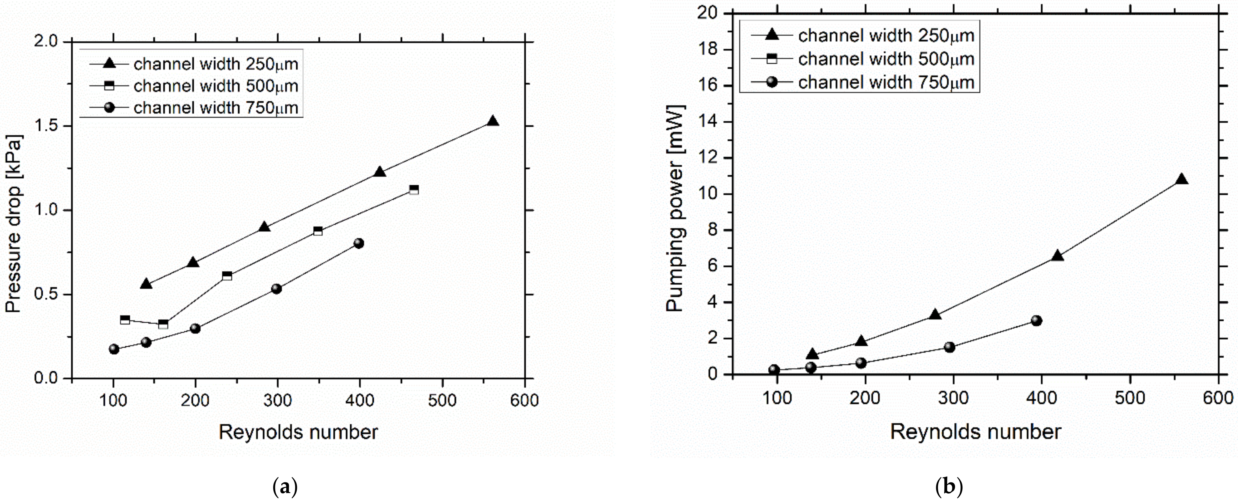
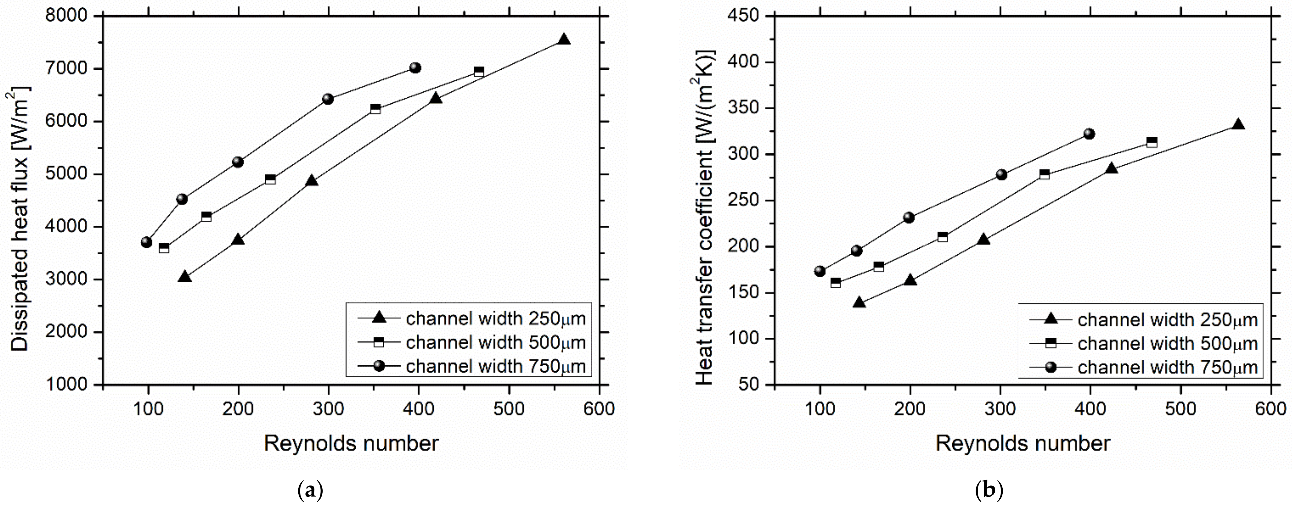
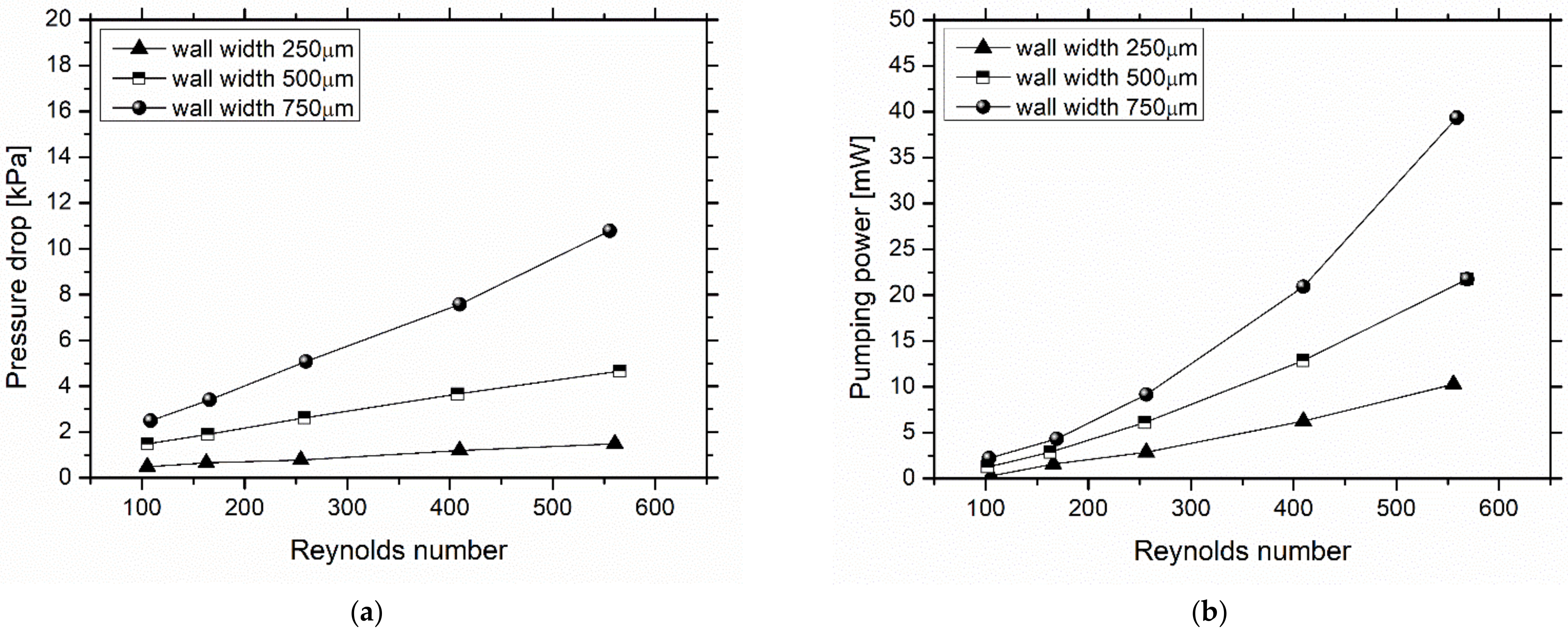
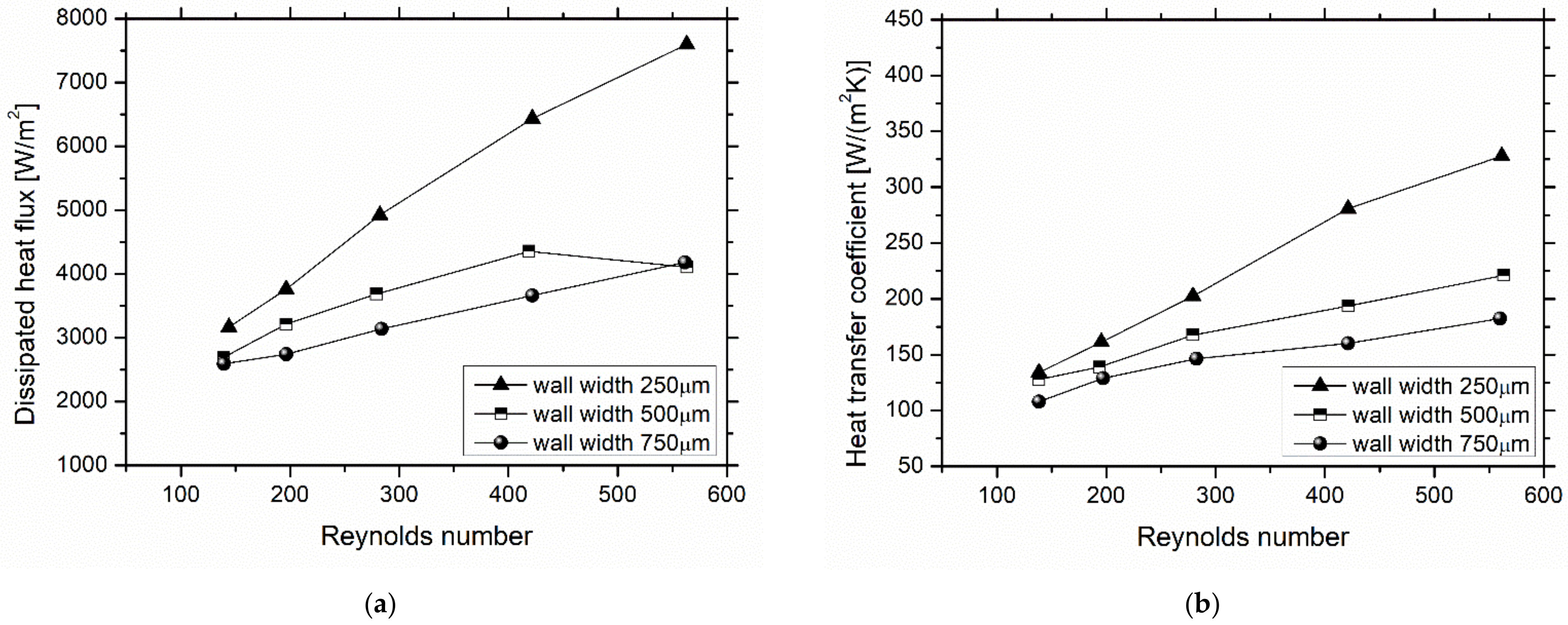
3.1. Effect of Heat Sink Geometry

Figure 1 and Figure 2 show the effect of varying the width of the microchannels, while keeping all the other geometric parameters fixed. While Figure 1 focuses on the pressure drop in consequent required pumping power, Figure 2 shows the heat transfer characteristics (dissipated heat flux and heat transfer coefficient). The width of the channels varied between 250 μm and 750 μm. This range was based on literature review and on our previous preliminary tests, which allowed us to narrow the working ranges. Figure 1 shows that, as expected, with the widening of the channel, the pressure drops in the exchanger are smaller. The pumping power is augmented with the increase in the flow of fluid drained, while also being larger for the narrower channels.
As for the values of the dissipated heat flux (Figure 2), the results show that more heat is removed from the heated surface, and its value is consistently larger the wider the channel. Figure 2 also shows an increasing linear trend for the heat transfer coefficient with the Reynolds number. This value also increases with the widening of the channel, which is attributed to an increase in the wetting/contact area. For lower Reynolds number values, a higher heat transfer coefficient is observed when the channel is wider.
Figure 3 shows the values of pressure drop and pumping power for geometries with the same channel width, but now varying the wall width between 250 μm and 750 μm. Analyzing the data in the figure, an increasing linear trend for the pressure drop can be observed, with an increasing widening of the wall, which consistently leads to larger values of the pumping power. As for the heat transfer, Figure 4 shows that for narrower walls, the flux dissipated is larger, as the thermal resistance of the wall material (which is a low conductor) is smaller. Consequently, one observes an increasing linear trend for the heat transfer coefficient with the narrowing of the wall. As expected, in all the cases analyzed up to this point of the discussion, the heat transfer and pressure drops increase with the flow rate (higher Reynolds number). For lower Reynolds number values, a higher heat transfer coefficient is observed when the wall is narrower.
After evaluating the effect of the geometry on cooling, one may conclude that in terms of maximizing heat transfer vs. dealing with the pumping requirements, wider channels with thinner walls lead to better performances of the heat sink. Naturally, as mentioned above, wider channels allow lower pressure drops in operation, increasing the wetted area, which in turn improves the heat transfer. A geometry with thinner walls allows for a wider number of channels, so there is a more effective heat transfer area to exchange heat. The results obtained for the effect of the channel width are inconsistent with the literature [24,25]. This can be so since the material used for the heat sink (PDMS) has low thermal properties, especially when compared to the base (stainless steel), so there are possibly more heat exchanges with the base than with the heat sink. In terms of fabrication, there are multiple advantages in using an inexpensive polymer such as PDMS, which is very easy to work with. The low thermal properties can be overcome by doping the PDMS with metallic nanoparticles, a technique that is currently in development.
These main dimensions and characteristics were introduced in the genetic algorithm. Although the final version of the algorithm has not yet been completed, preliminary results point to a maximization of the number of channels and width of the walls, in agreement with the results reported in [25]. Channels with an “optimum” diameter of the order of 300 μm result in optimum heat transfer, with temperature differences of the order of 40 °C and a minimal pressure drop of the order of 103 Pa.

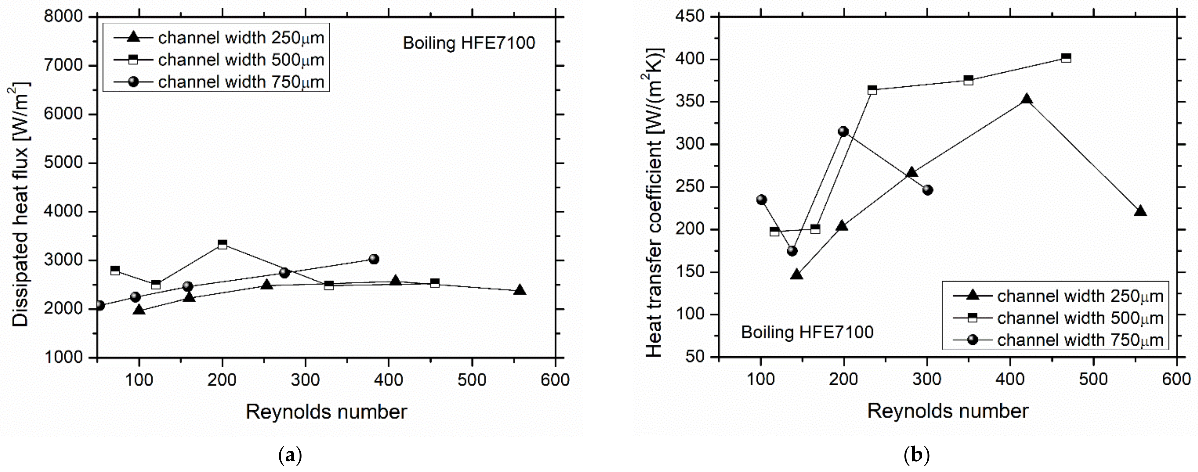
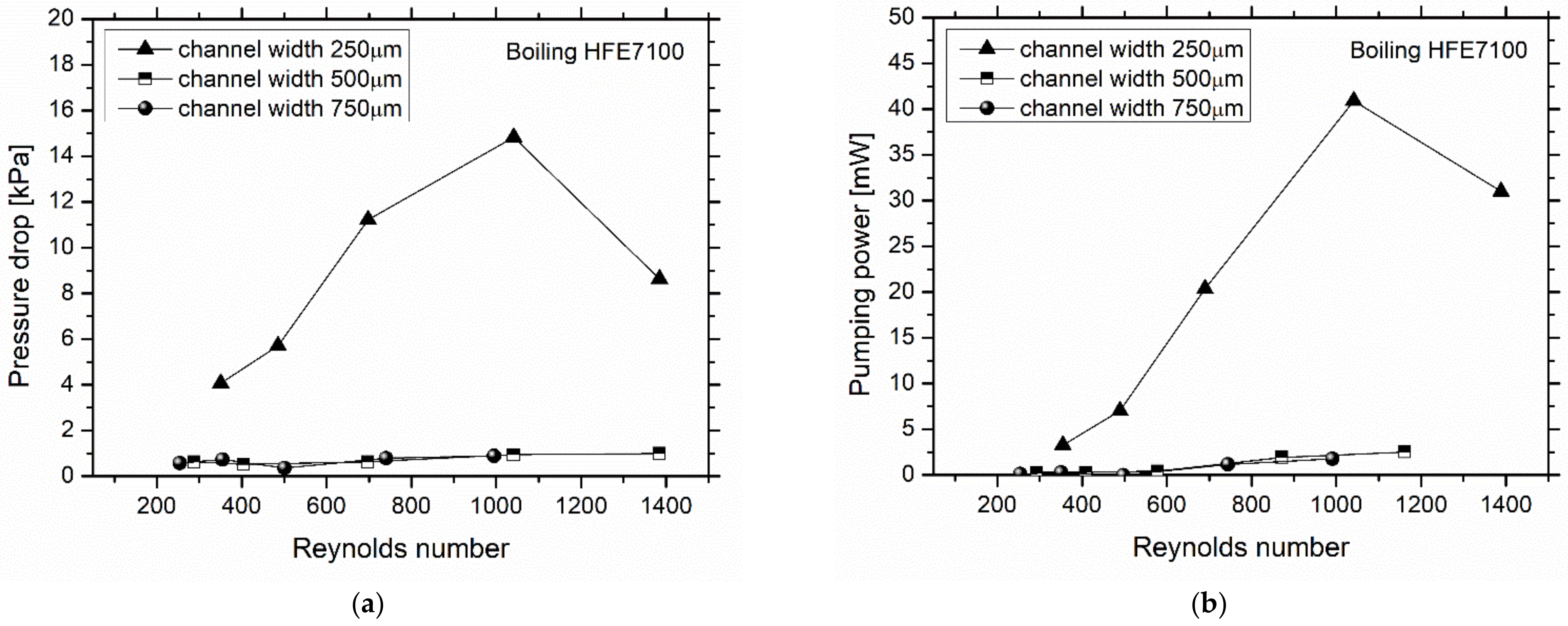
3.2. Potential of Using Flow Boiling Heat Transfer

The results discussed so far did not consider liquid phase change, although phase change may potentiate higher heat transfer rates due to the additional term associated with the latent heat of evaporation. However, higher penalties may arise in terms of pumping power if large bubbles are formed. In this context, Figure 5 confirms our previous results, i.e., narrowing the channel leads to higher pressure drops and consequently to higher pumping power; this further confirms our concerns regarding the use of working conditions that lead to flow boiling. In this case, the fluid used has a lower saturation temperature when compared to water (near to 64 °C at atmospheric pressure), such that liquid phase change can be observed. According to Manetti et al. [26], the starting diameter of the HFE 7100 bubble at the nucleation sites can be as large as 500 μm. Since the diameter of the bubble is larger than the hydraulic diameter of the thinnest channel, the channel may have become clogged, hence leading to the large pressure drop observed for the narrower channel geometry. Figure 6 shows the values of the heat transfer coefficient and the dissipated flow. Analyzing the heat transfer data in the boiling tests, it is possible to observe a large fluctuation of the values with a large standard deviation. Thus, one cannot infer the effect of the geometric parameters in this cooling method. However, it is possible to observe a tendency of the dissipated heat flux to be approximately constant when increasing the Reynolds number. To better understand these fluctuations, a detailed high-speed thermal analysis was performed. In Figure 7, it is possible to observe the evolution of temperature over time, during the cooling of the steel foil. This figure also shows the distinct phases of cooling through thermographic images. Some reddish flow lines can also be seen, which correspond to the coldest zones of the selected area. These red lines correspond to the channels through which the fluid flows. Although the method of cooling through the latent heat of vaporizing a fluid has great potential to dissipate large amounts of heat, it is a method that requires a more substantial control of the operating conditions of the system due to the aforementioned clogging issues. High-speed images, which are not shown here due to paper length constraints, clearly show the presence of vapor bubbles in the channel. As the flow develops, the presence of bubbles can be observed in all the channels of the exchanger. Since all flow rates used in the tests were low, it was only possible to identify the biphasic flow regime with bubbles (bubbly flow). High-speed images also depict a reversal of the flow of steam in some channels, which leads to high fluctuations in the measurements of the flow rate, pressure, and temperature. The reversal of the flow in a few channels in the heat sink is enough to cause a poor distribution of the fluid through the channels, making the cooling less homogeneous on the surface, while possibly obstructing the channels and generating a large pressure drop, as previously discussed.
Temperature differences of the coolant are of the order of 30–40 °C, which, despite the microscale addressed here, are useful for a secondary process. In this case, the energy is used for a desalination process using a superhydrophobic modified membrane (whose details cannot be revealed as they are under patent).
Despite the of the possibilities that come with the use of phase change, its potential is limited due to flow instabilities occurring that result from bubble formation and detachment. To cope with that, enhanced surfaces can be used to further promote heat transfer while keeping bubble dynamics under control. These features are now detailed in the following paragraphs.

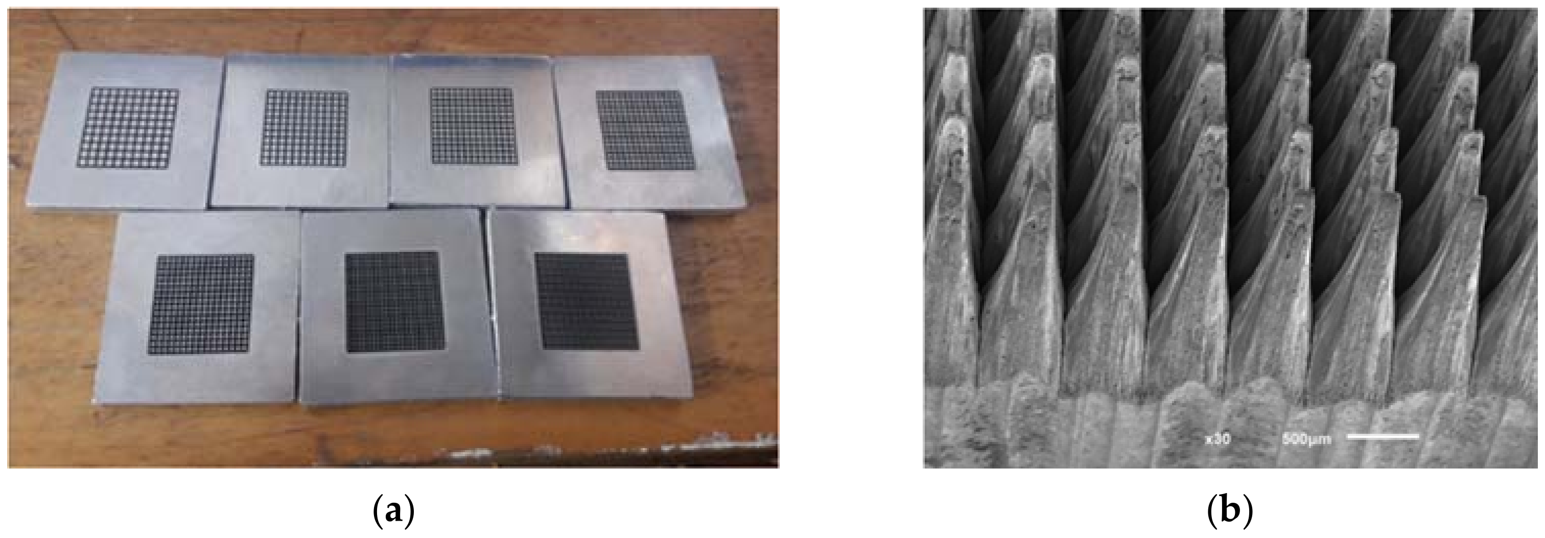
3.3. Potential of Using Enhanced Surfaces

There are several studies that present instabilities in bubble formation and even reverse flow in phase change flow boiling [27,28,29,30,31,32,33]. This issue causes a rise in pressure drop, and consequently in the pumping power, and significant oscillations can also be noticed in the inlet and outlet temperatures. Although the use of flow restrictors, acting as a pressure drop element can be a helpful tool for preventing reverse flow, these components increase the pumping power. Furthermore, their value in increasing the heat transfer performance for mass flow rates has not yet been proven [34].
Enhanced surfaces can have a high potential for these applications. By introducing artificial cavities to promote nucleation, bubbles can form much earlier instead of nucleating in a saturated or superheated bulk liquid, where the bubble growth rate is extremely high due to the sudden release of the liquid superheat at the liquid–vapor interface, resulting in a rapid expansion where bubbles coalesce and occupy a significant part of the channel, pushing the liquid in both the upstream and downstream directions. The ideal size of the nucleation cavities are functions of the local wall and bulk fluid temperatures, heat transfer coefficient, and heat flux [35].
Another important key element in the dynamic behavior of a bubble is the wettability characteristics of the surface, given the fact that it changes the bubble contact area and posteriorly affects the boiling performance. It has been found that as the contact angle of bubble increases, the nucleation site density increases, which consequently means that bubble diameter and the wall superheat temperature decrease, preventing coalescence from happening so fast [36].
Reverse flow occurs mainly because of the pressure increase caused by the rapid growth of the bubbles. In order to create a constant downstream flow inside the channel, build-up pressure must be relieved and vapor plug acceleration prevented. For this pressure relief, geometry plays a preponderant role. Another case study would be the creation of a deceleration along the heated surface, forcing the flow to move downstream by allowing the vapor plugs to grow with a constant interface velocity [37,38]. The idea is to decrease velocity along the pipe, as the cross-section area of the channel tends to increase in the direction of the fluid flow. Figure 8a,b represent an idea of enhanced surface for flow boiling in plane plate and heatsink.

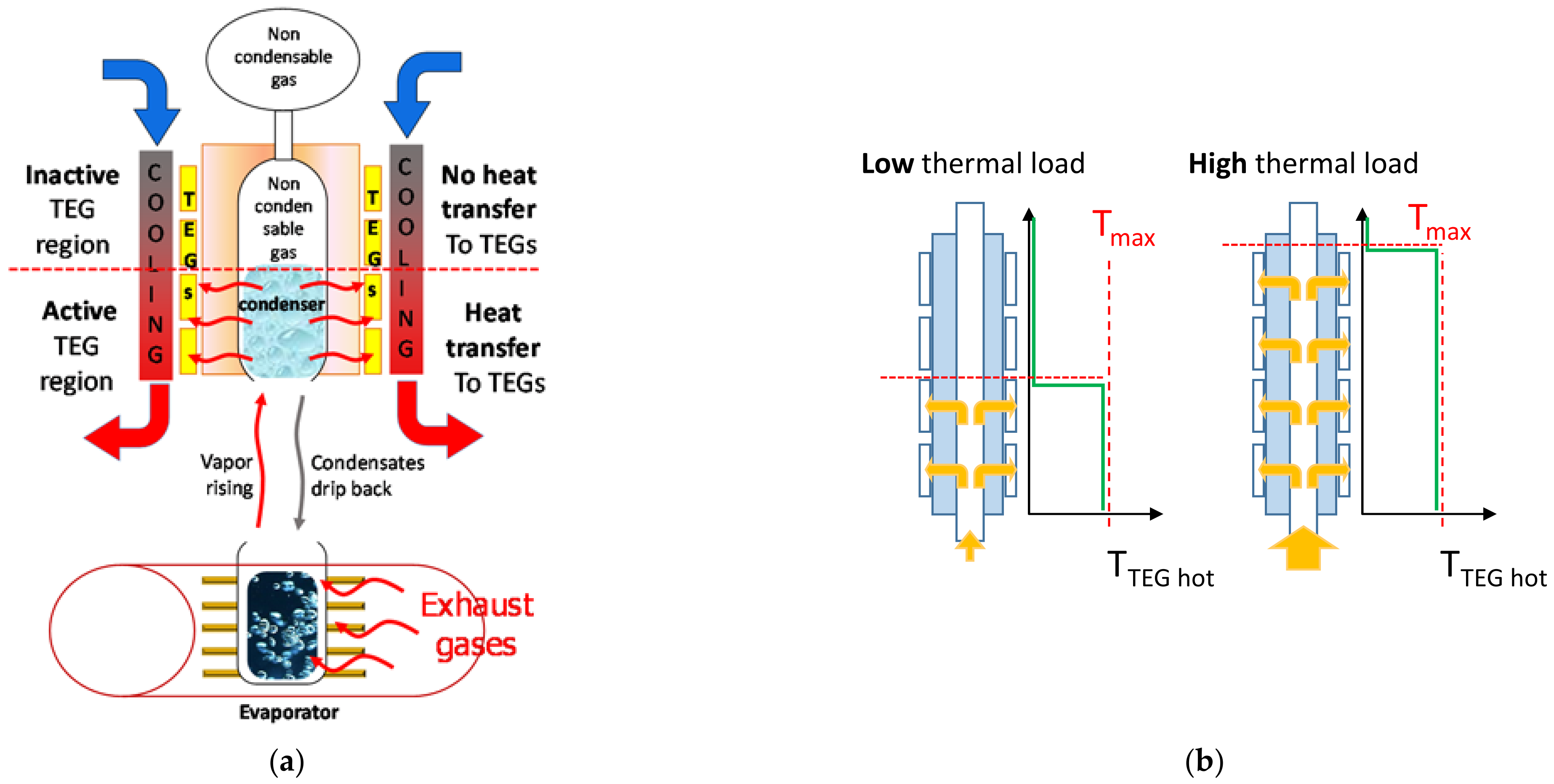
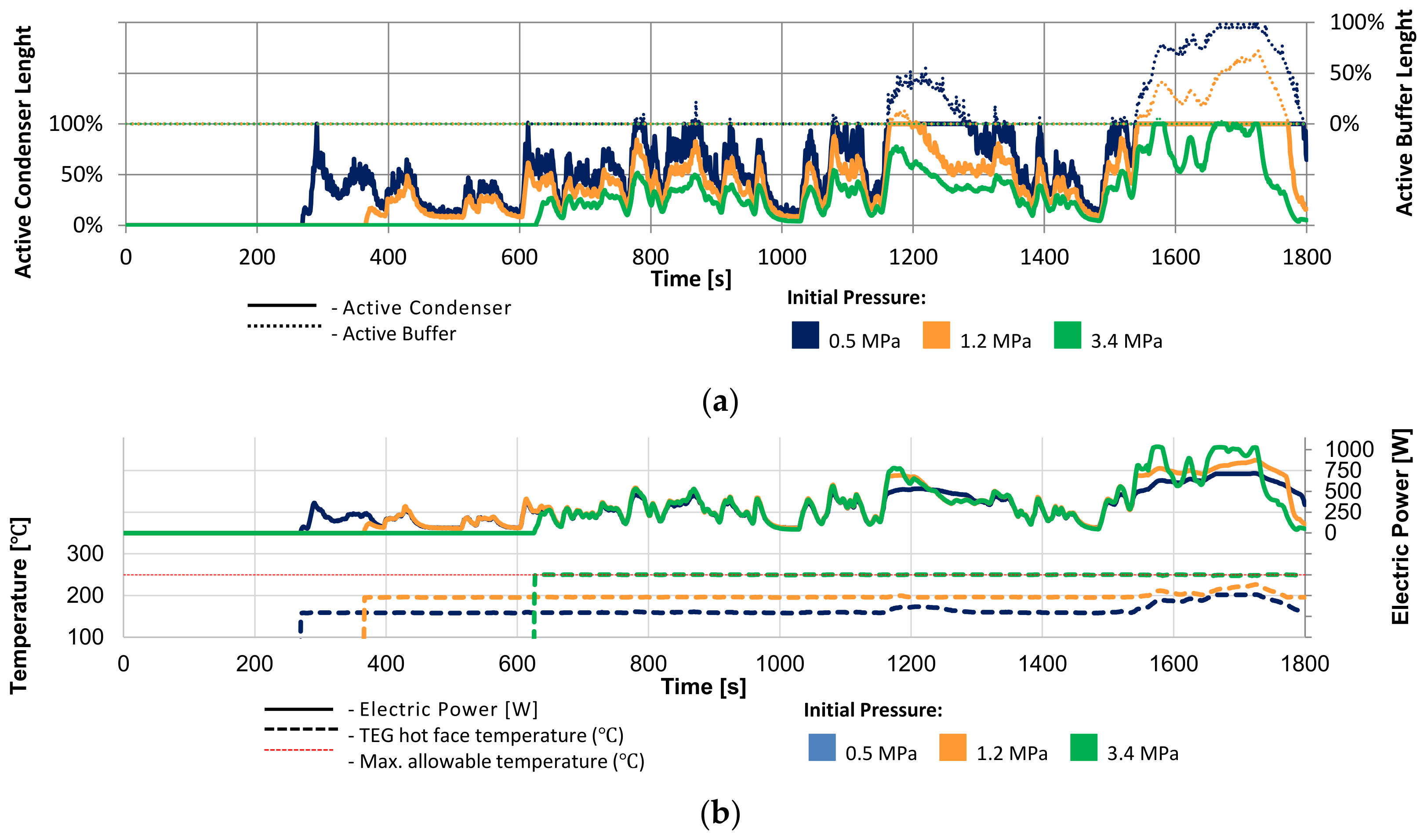
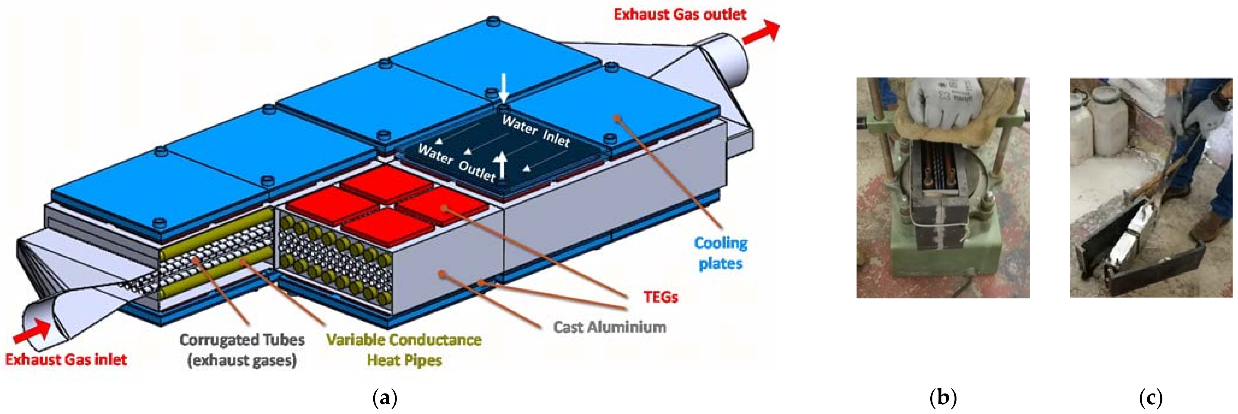
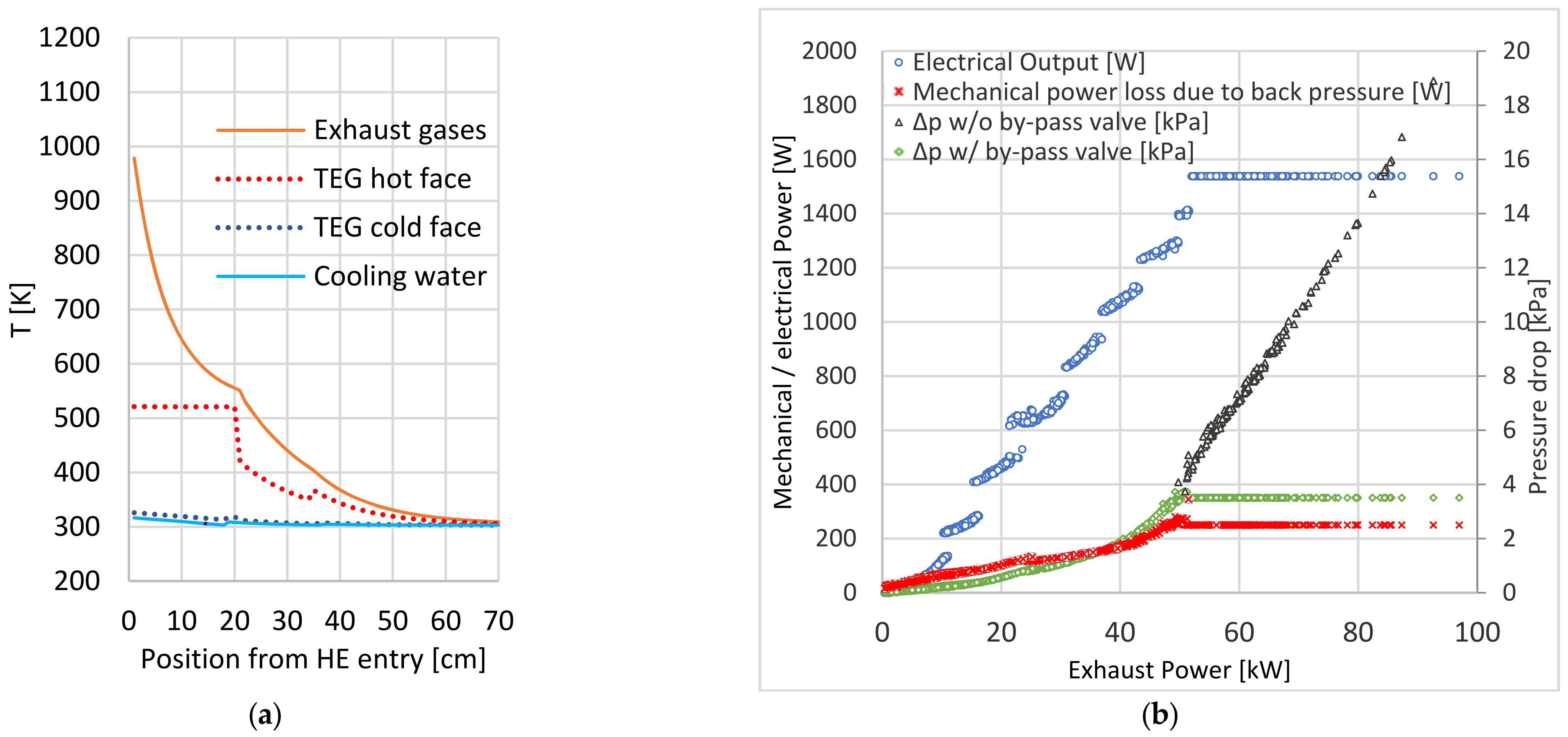
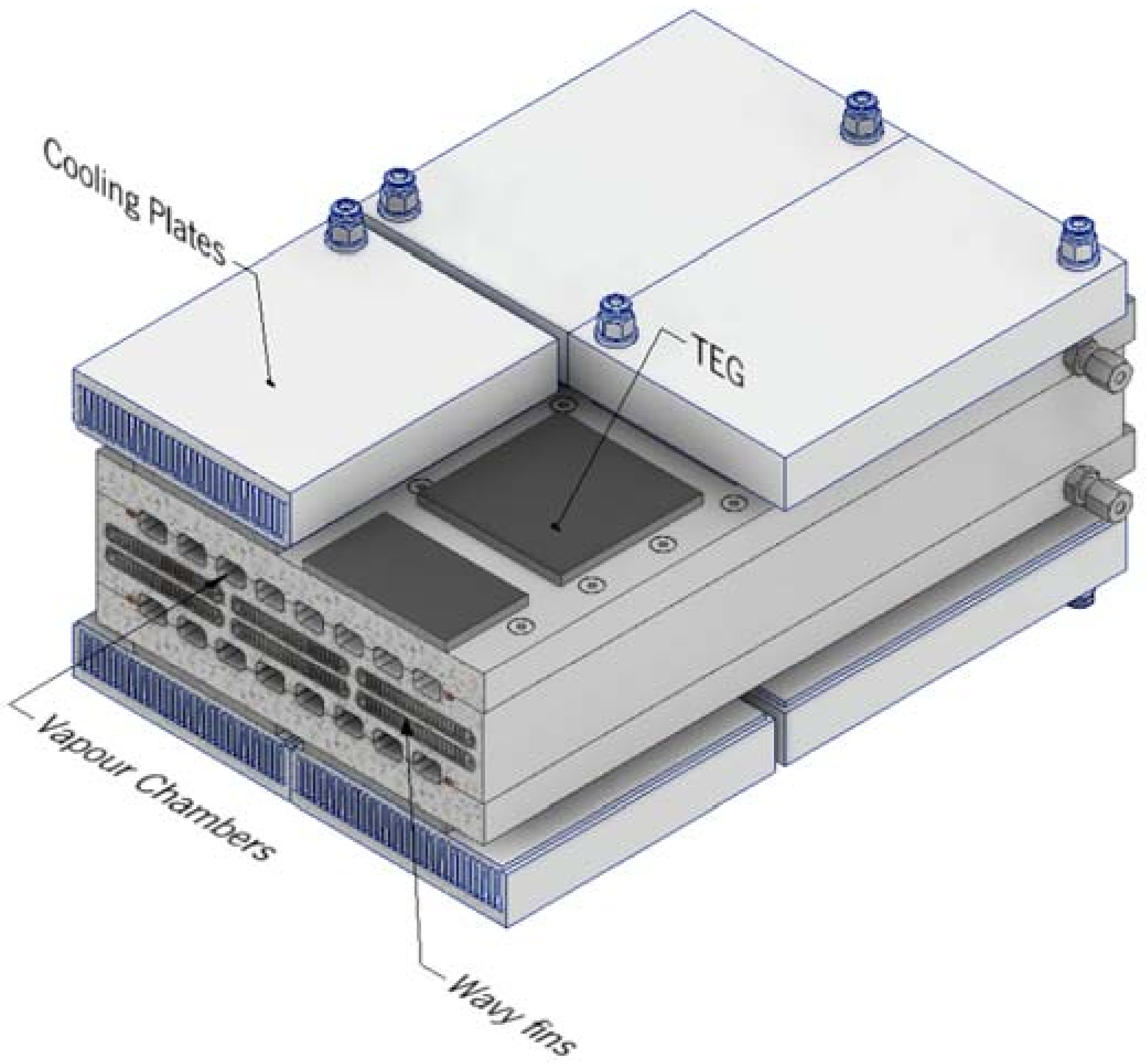
3.4. Potential of Using Variable Conductance Thermosiphons/Heat Pipes

The stable operating temperature characteristic of variable conductance heat pipes and thermosiphons is highly advantageous for heat supply and cooling applications that require some degree of thermal control or thermal stability. In particular, VC devices can be used in applications where heat from a thermally unstable source must be thermally stabilized so that it may be supplied to a sensitive target application. This has been accomplished by the authors in automotive thermoelectric generators in several ways, as detailed further ahead. These devices can also be used in cooling applications requiring temperature stability: the saturation temperature of the device may be set to the value intended for the cooling process as long as the heat transfer limits are not overcome at the heat source and heat sink sections of the device.
In the TS concept proposed by the authors [4,39,40,41], as seen schematically in Figure 9, the hot face of the TEG modules is not directly attached to an exhaust heat exchanger. Instead, it is rather the TS evaporator that is attached to the exhaust heat exchanger. The hot faces of the modules are attached along the TS condenser length and thus only receive the exhaust heat indirectly via the TS. This way, the variable temperature exhaust heat is only supplied to the modules after being “rectified” to an ideal, fairly uniform temperature by the TS. Finally, the cold faces of the modules are attached to a water-cooled heat sink to keep them as cool as possible.
As said before, in these systems, the variation of the thermal load will not significantly affect the temperature of the modules but only the number of active modules. In other words, the available heat will be downgraded in its temperature to a certain value close to the saturation temperature and distributed along a proportional length of the TS condenser. Under these conditions, only a fraction of the modules (the ones located within the region reached by vapor) will receive this heat coming from the TS, while the modules located within the NCG region will be nearly inactive. The main advantages of this approach are that the active modules will always operate near top efficiency and are protected against overheating. In a conventional system, top efficiency would only be attained for narrow design conditions, with thermal dilution occurring under low thermal loads and overheating occurring under high thermal loads.
The concept of Figure 9 was assessed both theoretically and experimentally by the authors with several proof-of-concept models [39]. The concept was fully modelled and explored for realistic driving cycles [4,40]. The computation of the unsteady heat transfer process from the exhaust gases to the VC TS was performed using an implicit finite difference approach. The estimation of the rates of vaporization and condensation was complemented with the calculation of the liquid, vapor, and NCG masses and specific volumes, which enabled the prediction of the pressure and temperature evolutions inside the VC TS along the driving cycle, as shown in Figure 10 for the WLTC-3 driving cycle and different expansion tank volumes.
According to the computed volumes of the liquid, vapor, and NCG domains, a determination of the number of active TEGs was completed. A cold system start-up, including transient heat transfer calculations in fluids and solids, was implemented.
Note that the total volume of the system deeply affects the pressure range experienced during the operation. Despite the differences in pressure, the average generated power (~260 W) did not vary significantly for this driving cycle.
The effect of the pre-charge pressure on the active condenser length percentage was also assessed, as seen in Figure 11a. Note that there is also a buffer length, which is an extra volume that accumulates excess vapor. The inner temperature and the electric power are displayed in Figure 11b. In this work, average powers around 560 W and 280 W were predicted for a custom highway cycle and the WLTC cycle, respectively. It was estimated that roughly up to 6% savings in fuel and CO2 emissions could be achieved due to the chain of inefficiencies avoided with the reduction of alternator operation [4].
While the TS configuration applied to the absorption of heat from engine exhaust gases is effective in terms of the return of the condensates to the evaporator by gravity assistance, it requires a vertical or at least an inclined geometry. On the contrary, HPs are able to operate horizontally or even slightly against gravity. Likewise, in the TS thermoelectric concepts mentioned above, the heat is supplied to the thermoelectric systems exclusively through the phase change process. This raises two challenges. On the one hand, the phase change device must be designed for the highest thermal load intended to be absorbed, which may be a lot. Moreover, exhaust heat can never be fully utilized, as the lowest temperature that can be attained for the waste heat leaving the system is the saturation temperature of the system (in the present case, around 250 °C). This might be a problem in cold starts and in Diesel engines, which typically display lower exhaust temperatures than petrol ones (Diesel engines always operate with a substantial excess of air).
An alternative way of implementing thermal control would be to also use a variable conductance (VC) device, this time a VC HP, but now in a parallel configuration; this means that the heat will reach the TEGs both through the conduction across the heat exchanger and the phase change in parallel, as proposed by the authors in a recently published patent application [41,42,43]. The HPs would be embedded along the exhaust heat exchanger, between the heat source (exhaust gases) and the modules, as seen in Figure 8. The main function of HPs and the phase change would be solely to absorb local excess heat in case it existed, thus avoiding excess temperature. More specifically, the HPs would only be active under high thermal load events, once saturation conditions appear in hot spots, with the working fluid absorbing the excess heat by vaporization and spreading it from the overheated upstream regions to the under-heated downstream regions by condensation.
The clever part of this latter concept seems to be that, unlike the control of excess heat through the bypassing and wasting of a part of the exhaust flow, this excess heat is not wasted but is spread over the downstream regions of the heat exchanger that are below the optimal temperature, as illustrated in the upper part of Figure 8a. This process is performed automatically, as boiling would automatically start occurring at hot spots once saturation conditions are met, thus cooling them. Then, the vapor produced with this excess energy would condense at the cooler spots reached by the vapor raising their temperature. Such a process would have the effect of inducing an optimal TEG operating temperature along the region of the heat exchanger reached by the vapor. In the remaining length of the system not reached by vapor, the heat transfer would continue to occur by simple conduction. This means that theoretically, the whole available exhaust heat could be utilized by the system, unlike the TS concept, in which the exhaust gases would only be cooled, at best, down to the TS temperature.
One application of such concept was proposed [3] using corrugated pipes for the exhaust flow and VC HPs, all embedded in a cast aluminum matrix to which the TE modules were attached, as depicted in Figure 12a.
The concept was modelled in the same publication. It consisted of a longitudinal discretization of the heat exchanger, with heat transfer and thermoelectric calculations being performed in each longitudinal section. Without the existence of excess heat, the HP would be considered adiabatic. In the event of the existence of excess heat, the condition of an active HP would be applied, with an estimation of vapor production and accumulation. Energy and vapor balances would then be performed between the longitudinal sections. In the region immediately downstream of the excess heat region, the vapor produced from the excess heat would be consumed (condensed), until a longitudinal position is reached where this vapor would be eventually depleted.
Some of the results predicted by the model are presented in Figure 13. The temperature profile of the exhaust gases, cooling water, and TEG faces along the longitudinal direction of the heat exchanger are shown in Figure 13a for one of the time steps of the custom HW cycle. It is worth noting the following: The flat region of the TEG hot face temperature corresponds to the length where the HP is active (vapor region). In this region (until 20 cm from the entry), the TEGs display the optimal temperature (250 °C), which is the saturation temperature of the VC HPs. This means that in this region, the HPs are active, that is, vapor is being produced at the hotter region upstream, preventing the TEG from overheating and condensing this vapor at the contiguous downstream region.
Figure 13b displays the electric power produced, the pressure drop, and the corresponding engine power loss due to the back pressure caused by the generator, for each time step of the custom HW driving cycle, as a function of the exhaust power [3]. There is a fairly linear increasing tendency for the electric power, up to around a 50 kW exhaust power, after which it stabilizes around a maximum value of 1.5 kW. This means that above 50 kW, the system is at full capacity, so the power could only be further increased if a larger system (more TEG modules) was implemented.
A solution to avoid excess pressure drop was considered here: the idea was to implement a bypass valve that would open above 2.5 kPa, avoiding an unnecessary additional pressure drop. This way, the pressure drop of the system would correspond to the yellow ones, topping at a maximum 2.5 kPa/350 W pressure drop/mechanical power loss.
Both the maximum power (~1.5 kW) and the average power (~570 W HW, ~250 W WLTC3) predicted for the system of such a small vehicle (light vehicle with 1.4 L naturally aspirated petrol engine) seem to be unparalleled in the literature [6].
Recently, a downsized proof-of-concept was successfully built (Figure 12b,c) and tested, confirming the effect of the excess heat spreading and the temperature limitation of the concept [44]. Unfortunately, the use of copper HPs was problematic due to the aluminum casting process, which degraded the material structure and made the HPs prone to leaks under pressure. A new prototype incorporating stainless steel HPs was subsequently built, allowing for the system to be tested under pressures capable of providing saturation pressures that enable heat spreading near the temperature limit of the modules (~250 °C).
Possible future improvements in the concept may include the elimination of the HPs, substituting them for vapor chambers machined within the aluminum matrix of the heat exchanger, as illustrated in Figure 14.
Flow instabilities are expected to be solved by following the approach suggested in [42]. This approach promises to enable the use of phase change thermal control without the need for high pressure fluids such as water and using lower pressure fluids such as DowTherm-A.
These vapor chambers, which may be considered as flat HPs, can have their surfaces texturized to enhance their boiling and condensation performance by using suitable laser texturing. The Vapor Chambers that would machine in lieu of the HPs could be fabricated based on the microchannel approach described in Case study I.
Textures can be created at the milli/microscale. One of the most recent ways to produce these textures is by removing material through the incidence of a laser beam. The generation of textures using laser is possible through numerous approaches, ranging from geometry, slot depth, and slot topology to the creation of dimples. Figure 15 shows some surfaces textured with a diode-pumped solid-state laser (DPSSL), Neodymium Doped Yttrium Orthvanadate (Nd:YVO4).
The idea would be to texturize the vapor chamber inner walls with textures optimized either for condensation or vaporization.
It seems clear that if it is possible to have systems with the characteristics of the concepts described, then this would boost the potential of automotive TEGs. Moreover, advances have recently been made in affordable TE materials, which could make these devices viable in the midterm [6,7,8]. More specifically, the authors were involved in the development of affordable silicide and tetrahedrite TE materials for automotive and industrial TEGs [42,43].

4. Conclusions

The present paper addresses two heat recovery system cases, for two macro-applications: the cooling of a PV cell where heat is recovered for a desalination. In the second case, heat recovered from exhaust gases is used in an innovative heat pipe, with variable conductance to be associated with a thermoelectric generator. This system can also be adapted for the use of laser textured vapor chambers machined into the heat exchanger body, further enhancing the concept. Both cases show the potential of using two-phase flows. However, instabilities at the microscale must be accurately addressed to take advantage of liquid phase change. In this context, micro-structured biphilic patterns, as those developed within our research group, may help to control such instabilities as they control the nucleation sites. This work also presents a detailed and innovative flow analysis that combines high-speed visualization with time-resolved thermography to optimize the geometry of the channels. The results obtained from the tests with the microchannel-based heat sink evidence an improvement in the dissipated power at the expense of controlled pumping power, for the best performing geometries.
The use of variable conductance thermal control strategies for exhaust thermoelectric generators was illustrated, with promising results, when compared with existing systems. The operation of the TEG modules near their top efficiency under highly variable thermal loads present in driving cycles may be explained by the ability of the available exhaust heat to have a high usability while still avoiding overheating and favoring an optimal module temperature irrespective of thermal load.

Author Contributions

Conceptualization, A.S.M., A.L.N.M., F.P.B. and O.C.; methodology, A.S.M., L.M., P.P., M.C., O.C., F.P.B. and A.L.N.M.; validation, A.S.M., P.P., L.M., M.C., O.C. and F.P.B.; formal analysis, A.S.M., A.L.N.M., F.P.B., O.C., M.C., F.P.B. and L.M.; investigation, A.S.M., P.P., L.M., O.C., F.P.B. and M.C.; resources, A.S.M., A.L.N.M. and F.P.B.; data curation, L.M., P.P., M.C., F.P.B. and O.C.; writing—original draft preparation, A.S.M., L.M., M.C. and F.P.B.; writing—review and editing, A.S.M., A.L.N.M., P.P., M.C., O.C. and F.P.B.; supervision, A.S.M., A.L.N.M., F.P.B. and O.C.; project administration, A.S.M., A.L.N.M. and F.P.B.; funding acquisition, A.S.M., A.L.N.M. and F.P.B. All authors have read and agreed to the published version of the manuscript.

Funding

Authors acknowledge to Fundação para a Ciência e a Tecnologia¸ FCT and PORTUGAL 2020 Partnership Agreement, through the European Regional Development Fund, for partially financing this project through projects PTDC/EME-TED/7801/2020, JICAM/0003/2017, UIDB/00481/2020, UIDP/00481/2020, and CENTRO-01-0145-FEDER-022083 (Centro2020) and for funding the scholarship of Pedro Pontes, ref. SFRH/BD/149286/2019.

Institutional Review Board Statement

Not applicable.

Informed Consent Statement

Not applicable.

Conflicts of Interest

The authors declare no conflict of interest.

References

  1. Seher, D.; Lengenfelder, T.; Gerhardt, J.; Eisenmenger, N. Waste Heat Recovery for Commercial Vehicles with a Rankine Process. In Proceedings of the 21st Aachen Colloquium Automobile and Engine Technology 2012, Aachen, Germany, 8–10 October 2012. [Google Scholar]
  2. Santos, H.; Morgado, J.; Martinho, N.; Pereira, J.; Moita, A. Selecting and Optimizing a Heat Exchanger for Automotive Vehicle Rankine Cycle Waste Heat Recovery Systems. Energy Procedia 2017, 107, 390–397. [Google Scholar] [CrossRef]
  3. Pacheco, N.; Brito, F.; Vieira, R.; Martins, J.; Barbosa, H.; Goncalves, L. Compact automotive thermoelectric generator with embedded heat pipes for thermal control. Energy 2020, 197, 117154. [Google Scholar] [CrossRef]
  4. Brito, F.; Pacheco, N.; Vieira, R.; Martins, J.; Teixeira, J.; Goncalves, L.; Oliveira, J.; Hall, M. Efficiency improvement of vehicles using temperature controlled exhaust thermoelectric generators. Energy Convers. Manag. 2019, 203, 112255. [Google Scholar] [CrossRef]
  5. Shen, Z.-G.; Tian, L.-L.; Liu, X. Automotive exhaust thermoelectric generators: Current status, challenges and future prospects. Energy Convers. Manag. 2019, 195, 1138–1173. [Google Scholar] [CrossRef]
  6. Pourkiaei, S.M.; Ahmadi, M.H.; Sadeghzadeh, M.; Moosavi, S.; Pourfayaz, F.; Chen, L.; Pour Yazdi, M.A.; Kumar, R. Thermoelectric cooler and thermoelectric generator devices: A review of present and potential applications, modeling and materials. Energy 2019, 186, 115849. [Google Scholar] [CrossRef]
  7. Liu, W.; Jie, Q.; Kim, H.S.; Ren, Z. Current progress and future challenges in thermoelectric power generation: From materials to devices. Acta Mater. 2015, 87, 357–376. [Google Scholar] [CrossRef] [Green Version]
  8. Finn, P.A.; Asker, C.; Wan, K.; Bilotti, E.; Fenwick, O.; Nielsen, C.B. Thermoelectric Materials: Current Status and Future Challenges. Front. Electron. Mater. 2021, 1, 677845. [Google Scholar] [CrossRef]
  9. Faghri, A. Heat Pipe Science and Technology, 2nd ed.; Global Digital Press: Columbia, SC, USA, 2016. [Google Scholar]
  10. Orr, B.; Akbarzadeh, A.; Mochizuki, M.; Singh, R. A review of car waste heat recovery systems utilising thermoelectric generators and heat pipes. Appl. Therm. Eng. 2016, 101, 490–495. [Google Scholar] [CrossRef]
  11. Reay, D.A.; Kew, P.A.; McGlen, R.J. Heat Pipes Theory Design and Applications; Elsevier: Oxford, UK, 2006. [Google Scholar]
  12. Royne, A.; Dey, C.; Mills, D. Cooling of photovoltaic cells under concentrated illumination: A critical review. Sol. Energy Mater. Sol. Cells 2005, 86, 451–483. [Google Scholar] [CrossRef]
  13. Bahaidarah, H.M.; Baloch, A.A.B.; Gandhidasan, P. Uniform cooling of photovoltaic panels: A review. Renew. Sustain. Energy Rev. 2016, 57, 1520–1544. [Google Scholar] [CrossRef]
  14. Akbarzadeh, A.; Wadowski, T. Heat pipe-based cooling systems for photovoltaic cells under concentrated solar radiation. Appl. Therm. Eng. 1996, 16, 81–87. [Google Scholar] [CrossRef]
  15. Escher, W.; Brunschwiler, T.; Michel, B.; Poulikakos, D. Experimental Investigation of an Ultrathin Manifold Microchannel Heat Sink for Liquid-Cooled Chips. J. Heat Transf. 2010, 132, 081402. [Google Scholar] [CrossRef]
  16. Guerrieri, D.C.; Naveira-Cotta, C.P. Numerical Analysis of Micro Heat Exchangers for Cooling of High Concentration Photovoltaic Panels. In Proceedings of the 3rd International Conference Computational Methods for Thermal Problems—ThermaComp2014, Lake Bled, Slovenia, 2–4 June 2014. [Google Scholar]
  17. Gogolin, A.; Wasilewski, M.; Ligus, G.; Wojciechowski, S.; Gapinski, B.; Krolczyk, J.; Zajac, D.; Krolczyk, G. Influence of geometry and surface morphology of the U-tube on the fluid flow in the range of various velocities. Measurement 2020, 164, 108094. [Google Scholar] [CrossRef]
  18. Guerrieri, D.C.; Naveira-Cotta, C.P. Experimental and theoretical analysis of a microchannel heat exchanger for high concentration photovoltaic cells. In Proceedings of the CONV-14: International Symposium on Convective Heat and Mass Transfer, Kusadasi, Turkey, 8–13 June 2014. [Google Scholar]
  19. Adham, A.M.; Mohd-Ghazali, N.; Ahmad, R. Optimization of an ammonia-cooled rectangular microchannel heat sink using multi-objective non-dominated sorting genetic algorithm (NSGA2). Heat Mass Transf. 2012, 48, 1723–1733. [Google Scholar] [CrossRef]
  20. Rao, R.; More, K.; Taler, J.; Ocłoń, P. Dimensional optimization of a micro-channel heat sink using Jaya algorithm. Appl. Therm. Eng. 2016, 103, 572–582. [Google Scholar] [CrossRef]
  21. Moita ASMoita Brito, F.; Pontes, P.; Martins, L.; Moreira, A.L.N. Complex fluid flows in mini and microchannels with micro and nano enhanced surfaces for advanced heat recovery systems. In Proceedings of the 16th Conference on Sustainable Development of Energy, Water and Environment Systems, 16th SEWES 2021, Dubrovnic, Croatia, 10–15 October 2021. [Google Scholar]
  22. Teodori, E.; Pontes, P.; Moita, A.S.; Moreira, A.L.N. Thermographic analysis of interfacial heat transfer mechanisms on droplet/wall interactions with high temporal and spatial resolution. Exp. Therm. Fluid Sci. 2018, 96, 284–294. [Google Scholar] [CrossRef]
  23. OpenFoamWiki. Chtmultiregionfoam 2019. Available online: https://openfoamwiki.net/index.php/ChtMultiRegionFoam (accessed on 10 April 2020).
  24. Upadhye, H.R.; Kandlikar, S.G. Optimization of Microchannel Geometry for Direct Chip Cooling Using Single Phase Heat Transfer. In Proceedings of the ASME 2nd International Conference on Microchannels and Minichannels, Rochester, NY, USA, 17–19 June 2004; pp. 679–685. [Google Scholar]
  25. Xie, X.L.; Liu, Z.J.; He, Y.L.; Tao, W.Q. Numerical Study of Laminar Heat Transfer and Pressure Drop Characteristics in a Water-Cooled Minichannel Heat Sink. Appl. Therm. Eng. 2009, 29, 64–74. [Google Scholar] [CrossRef]
  26. Manetti, L.; Ribatski, G.; de Souza, R.R.; Cardoso, E.M. Pool boiling heat transfer of HFE-7100 on metal foams. Exp. Therm. Fluid Sci. 2019, 113, 110025. [Google Scholar] [CrossRef]
  27. Kandlikar, S.G.; Steinke, M.E.; Tian, S.; Campbell, L.A. High Speed Photographic Observation of Flow Boiling of Water in Parallel Minichannels. In Proceedings of the 35th National Heat Transfer Conference, ASME, Anaheim, CA, USA, 10–12 June 2001. [Google Scholar]
  28. Li, H.Y.; Lee, P.C.; Tseng, F.G.; Pan, C. Two-Phase Flow Instability of Boiling in a Double Microchannel System at High Heating Powers. In Proceedings of the First International Conference on Microchannels and Minichannels, ASME, Rochester, NY, USA, 24–25 April 2003; pp. 615–621. [Google Scholar]
  29. Peles, Y. Two-Phase Flow in Microchannels—Instabilities Issues and Flow Regime Mapping. In Proceedings of the First International Conference on Microchannels and Minichannels, ASME, Rochester, NY, USA, 24–25 April 2003; pp. 559–566. [Google Scholar]
  30. Brutin, D.; Topin, F.; Tadrist, L. Experiment Study of Unsteady Convective Boiling in Heated Minichannels. Int. J. Heat Mass Transf. 2003, 46, 2957–2965. [Google Scholar] [CrossRef]
  31. Hetsroni, G.; Klein, D.; Mosyak, A.; Segal, Z.; Pogrebnyak, E. Convective Boiling in Parallel Micro-channels. In Proceedings of the First International Conference on Microchannels and Minichannels, ASME, Rochester, NY, USA, 24–25 April 2003; pp. 59–67. [Google Scholar]
  32. Steinke, M.E.; Kandlikar, S.G. An Experimental Investigation of Flow Boiling Characteristics of Water in Parallel Microchannels. J. Heat Transf. 2004, 126, 518–526. [Google Scholar] [CrossRef] [Green Version]
  33. Balasubramanian, P.; Kandlikar, S.G. Experimental Study of Flow Patterns, Pressure Drop and Flow Instabilities in Parallel Rectangular Minichannels. Heat Transf. Eng. 2005, 26, 20–27. [Google Scholar] [CrossRef]
  34. Kuan, W.K.; Kandlikar, S.G. Experimental Study on the Effect of Stabilization on Flow Boiling Heat Transfer in Microchannels. Heat Transf. Eng. 2007, 28, 746–752. [Google Scholar] [CrossRef] [Green Version]
  35. Kandlikar, S.G. High Flux Heat Removal with Microchannels—A Roadmap of Challenges and Opportunities. Heat Transf. Eng. 2005, 26, 5–14. [Google Scholar] [CrossRef]
  36. Ahmadi R, Okawa T Influence of surface wettability on bubble behavior and void evolution in subcooled flow boiling. Int. J. Therm. Sci. 2015, 97, 114–125. [CrossRef]
  37. Mukherjee, A.; Kandlikar, S.G. Numerical Study of the Effect of Inlet Constriction on Bubble Growth During Flow Boiling in Microchannels. Int. J. Heat Mass Transf. 2005, 73–80. [Google Scholar] [CrossRef]
  38. Lee, P.C.; Pan, C. Boiling heat transfer and two-phase flow of water in a single shallow microchannel with a uniform or diverging cross section. J. Micromech. Microeng. 2007, 18. [Google Scholar] [CrossRef]
  39. Brito, F.P.; Martins, J.; Hançer, E.; Antunes, N.; Gonçalves, L.M. Thermoelectric Exhaust Heat Recovery with Heat Pipe-Based Thermal Control. J. Electron. Mater. 2015, 44, 1984–1997. [Google Scholar] [CrossRef]
  40. Brito, F.P.; Alves, A.; Pires, J.M.; Martins, L.B.; Martins, J.; Oliveira, J.; Teixeira, J.; Goncalves, L.M.; Hall, M. Analysis of a Temperature-Controlled Exhaust Thermoelectric Generator During a Driving Cycle. J. Electron. Mater. 2015, 45, 1846–1870. [Google Scholar] [CrossRef]
  41. Brito, F.P.; Martins, J.; Goncalves, L.M.; Teixeira, J.; Pacheco, N.; Vieira, R. System for Efficient Heat Recovery. EU Patent application EP19190903.5, 8 August 2019. [Google Scholar]
  42. Brito, F.P.; Vieira, R.; Martins, J.; Goncalves, L.M.; Goncalves, A.P.; Coelho, R.; Lopes, E.B.; Symeou, E.; Kyratsi, T. Analysis of thermoelectric generator incorporating n-magnesium silicide and p-tetrahedrite materials. Energy Convers. Manag. 2021, 236, 114003. [Google Scholar] [CrossRef]
  43. Brito, F.P.; Peixoto, J.S.; Martins, J.; Gonçalves, A.P.; Louca, L.; Vlachos, N.; Kyratsi, T. Analysis and Design of a Silicide-Tetrahedrite Thermoelectric Generator Concept Suitable for Large-Scale Industrial Waste Heat Recovery. Energies 2021, 14, 5655. [Google Scholar] [CrossRef]
  44. Carvalho, R.; Pacheco, N.; Vieira, R.; Martins, J.; Gonçalves, L.; Brito, F.P. Experimental Validation of a Temperature-controlled Thermoelectric Generator Concept Developed for Recovering the Exhaust Heat of a Vehicle. In Proceedings of the Virtual Conference on Thermoelectrics, ITS, Online, 20–22 July 2021. [Google Scholar]
Figure 1. Effect of varying channel width on: (a) pressure drop and (b) pumping power for single-phase water flow in the heat sink.
Energies 15 01478 g001
Figure 2. Effect of the channel width on: (a) dissipated heat flux and (b) heat transfer coefficient for single-phase water flow in the heat sink.
Energies 15 01478 g002
Figure 3. Effect of the wall width on: (a) pressure drop and (b) pumping power for single-phase water flow in the heat sink.
Energies 15 01478 g003
Figure 4. Effect of the wall width on: (a) dissipated heat flux and (b) heat transfer coefficient for single-phase water flow in the heat sink.
Energies 15 01478 g004
Figure 5. (a) Pressure drop and (b) pumping power of the boiling HFE7100 flow in the heat sinks with varying wall width.
Energies 15 01478 g005
Figure 6. (a) Dissipated heat flux and (b) heat transfer coefficient of the boiling HFE7100 flow in the heat sinks with varying wall width.
Energies 15 01478 g006
Figure 7. Temperature variation during the cooling process taken with the thermographic high-speed camera for HFE7100 in the heat sink with a 500 μm channel width.
Energies 15 01478 g007
Figure 8. (a) Concept model of an enhanced surface with increasing cross-sectional area for a plane plate (b) and for a heat sink.
Energies 15 01478 g008
Figure 9. Outline of the temperature-controlled thermoelectric generator using a thermosiphon to supply the exhaust heat to the TE modules at a constant temperature: (a) full concept and (b) detail of the TS condenser with modules attached along its length for a low and a high thermal load.
Energies 15 01478 g009
Figure 10. Predicted pressure evolution inside the VC TS along the WLTC type 3 driving cycle, for several expansion tank volumes. For each condition, initial (pre-charge) pressure was adjusted for a 250 °C hot face temperature.
Energies 15 01478 g010
Figure 11. Effect of the pre-charge pressure on: (a) active condenser length percentage, (b) inner temperature and electric power (adapted from [4]).
Energies 15 01478 g011
Figure 12. (a) Global CAD drawing of the TEG generator concept incorporating helically corrugated pipes for the exhaust flow and heat and VC HPs in gold, with the cooling water plates in blue, the TEG modules in red; partial prototype under construction (b) prior and (c) after casting process.
Energies 15 01478 g012
Figure 13. (a) Temperature profile of the exhaust, cooling water, and TEG faces for an average exhaust power setting (instant 219 s of the HW driving cycle); (b) Electric power produced, pressure drop, and engine power loss due to back pressure caused by the generator (HW cycle). Adapted from [3].
Energies 15 01478 g013
Figure 14. Exhaust TEG generator concept evolution based on vapor chambers instead of HPs and wavy fins instead of corrugated pipes.
Energies 15 01478 g014
Figure 15. Textured surfaces made with diode-pumped solid-state laser (DPSSL), Neodymium Doped Yttrium Orthvanadate (Nd:YVO4) (a) Photos of the surfaces, (b) Detail of the topography obtained by SEM.
Energies 15 01478 g015
Table 1. Main uncertainties associated with the equipment used in this work.
EquipmentUncertainty
Syringe pump±0.035%
Thermal camera Onca MWIR-InSb-320±0.5
Absolute pressure sensor (250 kPa)±1.25 kPa
Absolute pressure sensor (160 kPa)±0.8 kPa
Type K thermocouple±0.5 °C
Publisher’s Note: MDPI stays neutral with regard to jurisdictional claims in published maps and institutional affiliations.

