Review

A Review on Plasma Gasification of Solid Residues: Recent Advances and Developments

1
Department of Mechanical Engineering, University of Trás-os-Montes and Alto Douro, Quinta de Prados, 5000-801 Vila Real, Portugal
2
LAETA-INEGI, Associated Laboratory for Energy and Aeronautics, Institute of Science and Innovation in Mechanical and Industrial Engineering, Rua Dr. Roberto Frias 400, 4200-465 Porto, Portugal
3
Mechanical Engineering Department, Suez Canal University, 4.5 Km the Ring Road, Ismailia 41611, Egypt
4
Faculty of Engineering, University of Porto, Rua Dr. Roberto Frias 400, 4200-465 Porto, Portugal
*
Author to whom correspondence should be addressed.
Energies 2022, 15(4), 1475; https://doi.org/10.3390/en15041475
Submission received: 29 December 2021 / Revised: 14 February 2022 / Accepted: 15 February 2022 / Published: 17 February 2022
(This article belongs to the Special Issue Renewable Energy from Solid Waste)

Abstract

:
The increase in production and consumption of goods has generated a surplus of waste, which destination is commonly the landfilling sites. This represents a major bottleneck in the production chain and creates new challenges for sustainable development. Due to the environmental and economic benefits, the use of renewable and ecological fuels derived from waste has received global attention. Plasma is one of the techniques that enable achieving renewable energy from solid residues, contributing to landfill avoidance and resource reutilization in line with the circular economy principles and supporting United Nations Sustainable Development Goals 7 (affordable and clean energy), 12 (responsible consumption and production), and 13 (climate action). This article presents a review and analysis of literature related to the use of plasma gasification of solid waste as a method of waste recovery. This article portrays the efforts that have been made in this direction and the barriers to the dissemination of technology for commercial applications. The focus of this article comprises (a) extracting valuable aspects from various studies, including laboratory and field studies, (b) summarizing the work done so far, and (c) compiling studies and findings on plasma gasifiers and recent developments.

1. Introduction

Waste should be a priority of European and national policy, municipal policies, and citizens’ concerns. The efficient management of these resources and the reduction of the associated environmental impacts can promote business opportunities and job creation [1,2]. Furthermore, a circular economy has been proposed by the European Commission and other regulatory agencies as a tool to enhance sustainability. Its main ambitions include the attainment of carbon neutrality through the promotion of the efficient use of resources while keeping them in the economy at their highest value for the longest time [3,4,5,6]. According to Nichols and Smith [7] over 2.1 billion tons of municipal solid waste (MSW) are generated worldwide each year. With such a high quantity of MSW, it has become essential to reintegrate it into the value chain, reducing the impacts caused to the environment, and ensuring human and animal health [8].
Currently, the most common methods for disposing of solid residues are landfills and incineration. However, due to their environmental, economic, and social impacts, such means of waste management are no longer favored. Thermochemical techniques, such as gasification, may be employed as strategies for converting waste into energy, providing a promising double benefit approach. They can be used not only to solve waste management problems but also to generate energy, playing a crucial role in addressing future global energy demands [9,10,11]. It is worth mentioning that, among all waste management techniques, gasification may be considered a carbon dioxide neutral method [12,13], being also environment-friendly by meeting legal emission limits [14,15]. Gasification leads to a mass reduction of 70–80% and a volume reduction of 80–90% of solid waste [16]. Gasification generally requires a lower temperature and produces fewer volatile pollutants when compared to other thermochemical techniques, such as combustion and pyrolysis, showing greater efficiency in terms of energy production and cost/benefit [13]. Nevertheless, despite its numerous advantages, biomass and waste gasification still constitute a small percentage (<1%) of the existing gasification market [17].
The abundance and composition of MSW, mainly the hydrocarbon fraction, increases its potential to be used as a feedstock for integrated plasma gasification cycles (IPGC) or integrated gasification cycles (IGC), with the dual-purpose of waste treatment and recovery of syngas and energy. This was verified in recent years, where the use of thermal plasma in gasification has gained increasing interest [15,18,19]. Using plasma gasification, the solid raw material can be decomposed into two products: a combustible synthesis gas and an inert glassy slag. Plasma gasification has been declared to have notable environmental advantages, both for atmospheric emission and for the control of slag toxicity [20,21,22,23]. However, as plasma gasification is a relatively new technology, knowledge on the performance and characteristics is still lacking [23].
Due to the operational sophistication and the involvement of numerous chemical reactions, together with complex phenomena of heat, mass, and moment transfer, a gasifier is a very intricate system. Gasification experiments are time-consuming and expensive, therefore syngas composition’s dependence on the operational variables is difficult to assess experimentally. Modeling based on computational mathematical models is considered a resourceful approach to investigate such a problematic and complex process. Using a model, one can get an adequate view of the process quickly and accurately. With the contribution of a simulation, sensitivity analysis, and optimization assessments are easily carried out, leading to considerable savings in time and resources. Literature shows several approaches to this, such as computational fluid dynamics (CFD), kinetic models, and thermodynamic equilibrium models, in association with gasification modeling [24,25,26,27].
Tungalag et al. [11] assessed MSW gasification by developing an equilibrium model using Aspen Plus and observed the waste decomposition into various gaseous species, such as synthetic gases, hydrocarbons, and tar in the pyrolysis phase. No dioxin formation was seen. Mazzoni et al. [28] studied the plasma gasification of MSW and hazardous waste from the oil and gas industry, developing a thermochemical model with Aspen Plus for the process simulation. The results obtained showed an efficiency of 24.3% for a mixture of 50% MSW and 50% petroleum hazardous waste (PHW). Munir et al. [8] reviewed the status of plasma gasification for waste processing. The results allow for concluding that plasma gasification has high financial costs and there is a great difficulty in reducing the expenses, despite the products generated during the process. Indrawan et al. [29] studied a plasma gasification model at low temperatures to convert solid waste into syngas. The results showed higher concentrations of hydrogen and carbon monoxide, however with lower energy efficiency than conventional gasification. Neves [30] studied the reduction of tar content using the plasma and observed that the tar collection was 52% lower when compared to conventional gasification. Ismail et al. [25,26] developed an Eulerian plasma gasification model to understand the effects of physical and chemical factors, such as the equivalence ratio, steam-to-fuel ratio, and plasma power. The model can simulate the temperature and velocity fields, as well as variations in the composition of gases and solids within the reactor. This brief review shows that the current research on biomass and wastes plasma gasification is scarce, therefore there is a need to deepen the knowledge in this field and try to explain the contribution of the technique for the waste-to-energy panorama, in the view of circular economy and sustainability principles. Plasma has shown to be beneficial for the revalorisation of plastic streams that are hard to recycle, such as polyvinyl chloride (PVC) or polypropylene (PP) [31,32].
This review presents a systematic documentary analysis based on the identification of the main works that deal with the use of plasma in the gasification of solid residues to produce syngas. Considering that plasma gasification is an emerging field, the literature mainly suggests a great evaluation of the technology taking into account parameters, such as operating conditions, plant efficiency, and other performance measures. The present works aim to bridge this gap by presenting a comparative analysis of IPGC plant modeling, with the objective of evaluating performance appraisal for a co-gasification study. The remainder of the article is organized as follows: Section 2 discusses the main objectives of SDGs 7, 9 and 13 considered in this plasma gasification review study. Section 3 provides an overview of the plasma gasification process. Section 4 discusses the numerical models used in the study, followed by the conclusion of the study.

2. Relation to Sustainable Development Goals (SDGs)

The study focuses on the SDGs related to the global environment and energy efficiency, i.e., SDGs 7, 9 and 13, which are directly or indirectly related to renewable energy and the environment. Hopefully, the development of research, such as the herein presented offers an opportunity to develop action plans that can build more environmentally concerned strategies to foster sustainability.
SDG 7 aims to ensure access to affordable, reliable, sustainable and modern energy for all [33]. The popularization of waste gasification systems over the last decade has made remarkable progress, providing access to electricity, increasing energy efficiency and expanding the use of renewable energy in the electricity sector [34]. Although many efforts to improve the energy system have shown some improvements, there is still a long way to go, as there is a huge gap to be achieved in terms of reducing the costs associated with implementing gasification plants in order to supply these demands; stagnant progress being seen in providing incentives [35]. Waste gasification can provide the production of renewable fuels and clean technologies for the co-generation and supply of energy, gas, and heat. Residential gasification is being underused and can be framed as a real solution to inequalities in access to reliable energy, especially in rural and peri-urban areas of the world [36].
SDG 9 focuses on building resilient infrastructure, promoting inclusive and sustainable industrialization and fostering innovation for the successful development of societies [33]. Industries and infrastructure need to be sustainable and updated to deal with future challenges, to unleash competitive and dynamic economic forces. Gasification works through the principles of a circular economy, that is, it assigns value to waste and keeps it in the economy for longer [8]. There is a great opportunity in the implementation of gasification plants, especially in developing countries, where they are forced to advance their manufacturing industries and increase investment in research and innovation [37]. The implementation of a structured network of small-scale gasification industries would not only solve logistical problems but would also provide the creation of new jobs.
SDG 13 preconizes urgent action to combat climate change and its impacts [33]. The levels of emissions of CO2 and other greenhouse gases in the environment have reached new records, and it is increasingly necessary to implement strategies that abate these emissions. Plasma gasification is a good example as it presents a higher-standard performance when compared to other waste management options, originating cleaner syngas from which several other commodities (usually produced from fossil fuel-based sources) may be achieved [38,39,40].

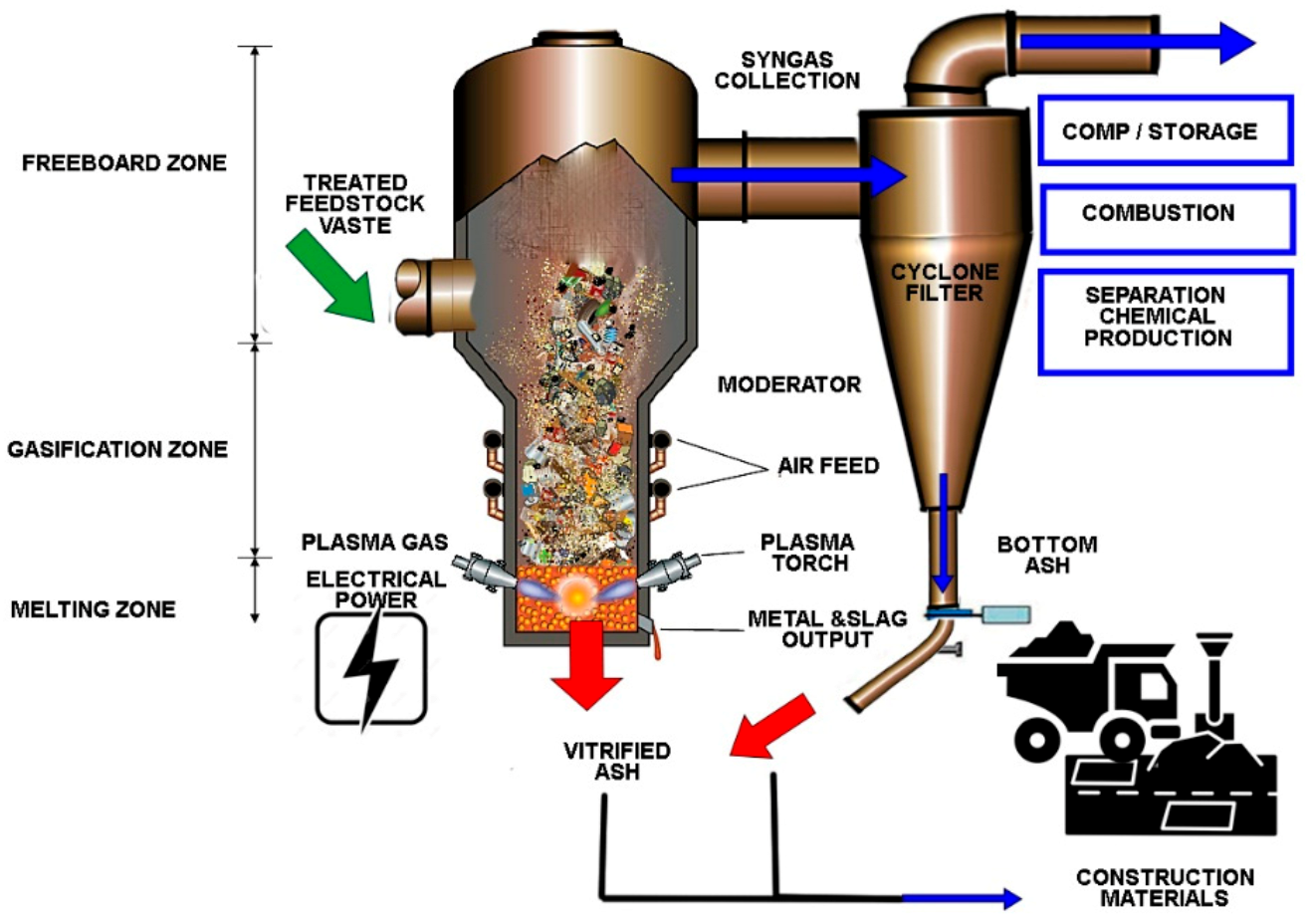
3. Overview of the Plasma Gasification Process

Gasification is defined as a method in which the raw material molecules are broken down into their elements at elevated temperature and atmospheric or elevated pressures [41]. The complex process mentioned must be carried out in the presence of a gasifying agent as steam, air, O2, CO2 or even mixtures of these [14,42,43]. Exposure of the raw material to the substoichiometric oxygen level leads to the production of synthesis gas that mainly involves hydrogen, carbon monoxide, methane, carbon dioxide, branched hydrocarbons, tars, and a negligible amount of nitrogen [44]. This gas has applications, such as combustion in engines to produce electric energy, heat generation, and as a raw material in chemical synthesis, among others [30]. Tars are condensable organic compounds formed in the gasification process. Tar species is a wide range of hydrocarbons that are mainly comprised of single-ring to five-ring aromatic hydrocarbons [45]. Figure 1 shows more information on the plasma gasification technical aspects.
Plasma is composed of high-temperature ionized gases that provide fast and efficient heat transfer. Plasma’s ability to transfer calories to incoming organic raw materials allows it to simultaneously pyrolyze them and provide thermal energy to conduct endothermic vapor reform reactions. This double benefit has been implemented with great success in systems such as US Patent No. 5.666.891, showing a variety of particularly useful configurations for arc electrodes. Here, the organic compounds contained in waste are destroyed by pyrolysis, caused by the high temperatures of the plasma breaking bonds in the organic molecules. When introducing steam into the process chamber, these constituents are converted into synthesis gas, a clean-burning fuel that consists mainly of CO, CO2, and H2, through the steam reforming reaction. Other constituents of waste, which do not volatize, are transformed into a molten state, which then cools to form a stable vitrified glass. Controlling the vitrification process, the resulting vitrified glass has stability against chemical and environmental components, with high resistance to leaching of the dangerous components bonded to the glass, showing interesting downstream utilizations [47].

3.1. Plasma Gasification

Plasma is the fourth state of matter and constitutes more than 99% of the universe [30]. It is composed of electrons, ions, and neutrals that are in fundamental and excited states. From a macroscopic point of view, plasma is electrically neutral. However, it does contain free charge carriers and is electrically conductive. Plasma is created by applying power to a gas to reorganize the electronic structure of species (atoms, molecules) and produce excited species and ions [17]. This energy can be thermal or carried by an electric current or by electromagnetic radiation. The most common plasmas generated from electrical discharge and their typical parameters are shown in Table 1.
Tendero et al. [48] detail the use of plasma under atmospheric conditions generated from an electrical energy source. The electric field transfers energy to the electrons in the gas (the electrons with the greatest mobility), the electronic energy being transferred to neutral species by collisions that obey the law of probability and can be divided into elastic and inelastic collisions. Most excited species are very short-lived and reach their fundamental state, while others have longer lifetimes since the energy transfer only occurs through collisions.
According to Baratelli [49] and Boulos et al. [50], plasma can be divided into two broad categories: thermal and non-thermal plasma. Thermal plasma, which is also classified as hot plasma, is thus defined as having a local thermodynamic balance, that is, all plasma components (electrons, ions, and neutrons) have a similar temperature, and this condition prevails throughout the column of the electric arc [49]. These are also known as local thermodynamic equilibrium plasma (LTEP). Chemical transitions and reactions must be governed by collisions, not radiation processes in LTEP. Furthermore, collision phenomena must be micro-reversible. This means that each type of collision must have its inverse equilibrium (kinetic equilibrium; excitation/disexcitation; ionization/recombination) [51]. Other requirements necessary for LTEP are that the local gradients of plasma properties (temperature, density, thermal conductivity) are small enough to allow a particle in the plasma to reach equilibrium: the diffusion time must be equal to or greater than the necessary for the particle to reach equilibrium [48]. Non-thermal plasma, which is also known as cold plasma or non-local thermodynamic equilibrium plasma (non-LTEP), is thus classified by the temperature of electrons being higher than the temperature of heavy components, such as ions and neutral particles [50]. In view of the huge difference in mass between electrons and heavy particles, the plasma temperature (or gas temperature) is fixed as described in [48]. The higher the LTEP output, the greater the temperature difference. The power density of the supply greatly influences the state of the plasma (LTEP or not). In general, a high-power density induces LTEP (e.g., arc plasmas), while non-LTEP are favored by a low power supply density or a pulsed power supply (e.g., microwave plasmas). In the latter case, the short pulse duration prevents the establishment of a steady state.

3.1.1. Types of Torches

A plasma generator, plasma torch, or plasmatron is both an electrotechnical and thermal equipment. It is a highly flexible instrument in its application. Plasma torches are used today in cutting, welding, melting, and refining metals, in alloys and ceramics, in extractive metallurgy, continuous casting of steel, deposition (plasma spray) of ceramic layers and surface protective metals, inertization of toxic chemicals, and hospital and industrial waste [52,53,54,55,56,57]. In addition, it is applied in the thermal decomposition of materials (for example, methane, ethanol, and other fuels to produce hydrogen), synthesis of chemicals (acetylene, calcium carbide, among others) and new ceramic materials (oxides, nitrides, carbides, among others). Furthermore, also notable is the use of plasma torches in spheroidization and ceramic phase change, heat treatment of surfaces, the recovery of metals from metallurgical fines [30,58], biomass gasification [59], waste treatment [60], and in reforming contaminant gases [61]. Recently, applications related to the environmental issue have gained more and more relevance [62].
Depending on the type of energy supply and the amounts of energy transferred to the plasma, the properties of the plasma change in terms of electronic density or temperature. These two parameters distinguish plasmas in different categories. The atmospheric plasma sources described in this article are closer to the luminescent discharges and the arcs. The excitation frequency is also important because it influences the behavior of electrons and ions. Atmospheric plasma sources can be classified according to their excitation mode. Three groups are highlighted:
  • DC (direct current) and low-frequency discharges;
  • ignited by radio frequency waves;
  • ignited by microwave discharges.
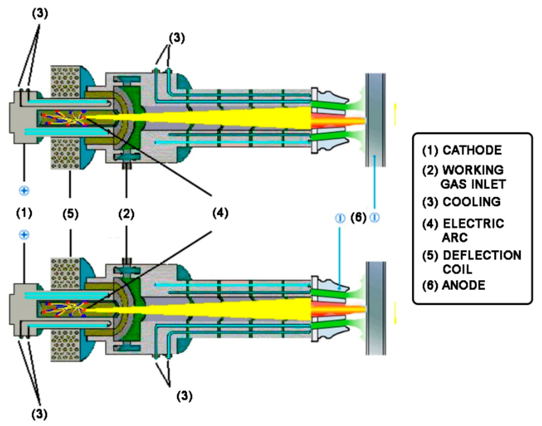
According to Paredez Angeles [58], the classification of plasma torches can be done under some basic aspects. The most widespread is the form of plasma production, such as electric arc torches with a direct current, an electric arc with alternating current, radiofrequency plasma, high-frequency plasma, and ultra-high frequency plasma. Normally, for conversion, the electric arc torch with direct current is used. There is a wide variety of shapes and configurations of types of torches that plasma gasification sets can adopt. Depending on the characteristics of the feedstock and equipment, one can have a plasma torch, consisting of one or more non-transferred AC (alternating current) or DC plasma torches, or a plasma torch with two non-transferred reverse polarity DC plasma torches.
It is known that induced coupled plasma (ICP) torches have some weaknesses. First, it is difficult to ignite a plasma at low frequencies (<150 kHz). For this reason, most ICP torches use an inert and easily ionizable gas in combination with a high-temperature hollow susceptor in which the waste material is introduced. In fact, many ICP torches use a much higher frequency than 150 kHz to ignite the inductively coupled plasma [30]. Second, it is quite difficult to sustain the plasma within an ICP torch when waste material is introduced directly into the ICP torch. Moreover, if the material contains volatiles, then this adds to the volume of gas within the torch itself. Consequently, the use of ICP torches to process waste inside the torch vessel is limited.
Non-transferred arc plasma torches using this technique include non-transferred AC and DC arc plasma torches. A variety of gases have been used with plasma torches, including but not limited to O2, N2, Ar, CH4, C2H2, and C3H6. Classical arc torches can be classified as LTE discharges. They are characterized by quite high temperatures and are used for applications where heat is required (welding, cutting, spraying, etc.), while low power pencil torches involve a non-LTE discharge—they create a “chemically rich environment” that is used for low-temperature applications.
Plasma torches can also be differentiated by the orientation they take in each set of equipment. Another important aspect is the operating power. There are sets of torches that operate at 300 kW but have the capacity to adjust the functioning power. We can also consider as relevant the presence of a gas reforming device, which can also be DC with copper electrodes cooled by water. In recent years, publications have sought to clarify these issues, seeking to correlate the types of torches, and understanding how to adapt these characteristics to those emitted. Regarding the constituent elements of the plasma torch, we can mention the basic components, such as electrodes (cathode and anode), a gas passage tube, a gas inlet chamber or vortex chamber, an arc stabilization system and electrode cooling [63]. The scientific production of articles reporting the gasification of biomass and MSW by plasma in the last two decades is sparse and sometimes lacks technical details about the torch and about the experimental conditions or the quality of the synthesized gas. In addition, there are more publications investigating the pyrolysis or kinetic behavior of the fuel counterparts and their mixtures, so this research will contribute to the body of knowledge in the field.

3.1.2. Electric Arc

The electric arc is an electronic structure formed by the cathode and anode assembly inside an evacuated chamber. When the cathode is heated, some electrons can leave the cathode surface towards the anode, forming an electrical discharge known as the thermionic effect. When a gas is introduced into this chamber, the electrons emitted by the cathode will collide with molecules of the gas and, thus, ionize and generate more free electrons to continue the bombardment process [49]. According to Godoy [62], the voltage drop in the electrodes is a function of the material and the type of gas used to generate the plasma, regardless of the length of the arc and the current. The voltage in the arc formed is dependent on the nature, temperature, and pressure of the atmosphere in which the arc is operating.
There are two types of electric arcs: the free electric arc in which the heat exchange process between the arc and the ambient gas takes place by natural convection; and the confined electric arc in which the process of heat exchange and the ambient gas take place by forced convection. The plasma torch is commonly used with a confined arc [63], and has greater efficiency when compared to the free arc because its temperature is approximately six times higher [58].
Plasma torches can be classified according to their dependence on the electrical arc used as non-transferred, transferred, and overlapped or mixed arc. In the non-transferred arc, the equipment operates with the cathode and anode in the same body [62], commonly presenting tubular and concentric geometry and its durability is directly affected by cathode erosion [49]. Usually, this type of arc is used for melting, refining, reduction, decomposition, and pyrolysis [64]. In the case of transferred arc, the equipment operates with one electrode on the torch (usually the cathode) and the other electrode on the material to be worked [64] and, generally, this type of electric arc is used for cutting metals [63]. Figure 2 shows torches with non-transferred and transferred arc.
Depending on the type of project, DC, and low frequency discharges can operate in continuous or pulsed mode. A pulsed working mode allows the injection of large amounts of energy into the discharge while heating the system is limited. On the other hand, a pulsed power supply is technically more complex than a DC power supply and compromises the reproducibility of the process [30].
The efficiency of a gasification process is evaluated based on several parameters, such as syngas composition, lower heating value (LHV), higher heating value (HHV), cold gas efficiency (CGE), carbon conversion efficiency (CCE) and tar and coal content [65,66,67]. The performance indicators listed above are set out below ( χ is the molar fraction of each component):
L H V M J N m 3 = 10.79   χ H 2 + 12.63     χ C O + 35.8     χ C H 4 100
C C E % = C a r b o n   c o n t e n t   i n   t h e   s y n g a s × s y n g a s   f l o w   r a t e C a r b o n   c o n t e n t   i n   t h e   f e e d s t o c k × f e e d s t o c k   f l o w   r a t e × 100
C G E % = L H V   o f   t h e   s y n g a s × s y n g a s   f l o w   r a t e L H V   o f   t h e   f e e d s t o c k × f e e d s t o c k   f l o w   r a t e × 100
H H V k J k g = 874.08   1 / 3     χ C O + χ H
The quality of the producing gas and the efficiency of the process directly depend on a wide spectrum of variables, from the properties of the raw material to the operating conditions and types of gasifiers used [12,18,68]. Among all the effective parameters, temperature, and the equivalence ratio (ER) play a crucial role in which the quality of the synthesis gas is strictly dependent. Regarding the impacts of temperature, it is noticed that high temperature favors H2 yield, as well as the general gas yield, promoting greater calorific value, in addition to intense thermal cracking reactions [69,70]. The equivalence ratio, a ratio between the actual concentration and the stoichiometric oxygen concentration, plays a key role in the gasification process [18]. Increasing ER increases the likelihood of oxygen/volatile reactions causing significant changes in syngas composition and tar proportion [70]. In addition, higher ER results in a reduction in syngas heating value [71]. The optimal ER is proposed in the range of 0.2 to 0.4 for an efficient gasification process [17,72].

3.1.3. Microwave Induced Plasma (MIPs)

Microwave plasma gasification has been discussed as a promising technology, according to [11], due to a relevant increase in gasification efficiency while eliminating the use of catalysts. The microwave signal is created by a magnetron and travels through the waveguide to form plasma. The system uses no electrode and requires less energy consumption compared to arc plasmas. Most studies in the field of microwave plasma gasification are related to the gasification of biomass, MSW, and coal for electricity or heat generation as a power plant. Another promising advantage of microwave plasma power plant technology is dispatch flexibility due to its fast start-up and shutdown capabilities. Thus, the plant can operate both in an isolated system and in parallel with the integrated energy system. In this sense, the plasma-enhanced gasification plant can be considered one of the most flexible renewable energy resource systems.
All microwave systems, without electrodes, operate on the same principle. Microwaves are guided through the system and energize the electrons in the plasma gas. An elastic collision occurs between an electron and a heavy particle. Due to the large mass of the heavy particles, electrons collide and the heavier particles become stationary. The electrons are thus gradually accelerated (increasing kinetic energy) and the heavy particles are slightly heated. After several elastic collisions (which follow probabilistic laws), the electrons obtain enough energy to produce exciting or even ionizing inelastic collisions. The gas is partially ionized and becomes plasma that supports microwave propagation. A microwave torch is a set that can be subdivided into four large groups: the microwave power source (power supply, magnetron, and circulator to protect the magnetron from reflected energy); the microwave equipment (waveguides, tuning system); an ignition system; and gas injections.
The great differential of microwave gasification is its ignition by discharge. The self-ignition of the discharge guarantees flexible operating conditions and enables the industrialization of the process. The energy imparted to the electrons in the gas must be high enough to start the plasma. In the literature, several methods are suggested to concentrate microwave energy. These atmospheric MIPs can be classified into three categories [48], as seen in Table 2: (1) resonant cavity plasmas; (2) free expansion torches; (3) microplasmas.
Tungalag et al. [11] used experimental apparatus of the microwave plasma system used for MSW pyrolysis and emission gas reform. The main experimental setup consists of a pyrolysis reactor, a microwave generator, a reactor equipped with a microwave plasma torch, gas filter, and gas analysis systems, including a data acquisition system.

3.2. Plasma Gasifying Agent

In high-temperature plasma gasification, the most common gasification agents used are air, steam, oxygen, and their mixtures [73,74]. Gil et al. [75] compared the performance of air, steam, and steam-oxygen mixtures in biomass gasification. Pure steam performed better in relation to operating conditions and syngas composition (higher H2 yields and higher LHV), being suggested by several other authors as the most adequate gasifying agent for higher hydrogen production [73,74,76]. Air is also commonly applied as a gasifying agent. Although the synthesis gas produced is highly diluted by nitrogen (with LHV usually between 3.5–7 MJ/Nm3), it has the potential to be used for electricity production or heat generation [75,76,77]. Ong et al. [78] tested different air flow rates in the co-gasification of sewage sludge and wood chips and reported higher temperatures inside the reactor to increase flow rates. This was due to the promotion of exothermic combustion reactions, which released more energy. They also studied the effect of the air flow rate on syngas composition and found that when this parameter was increased, CO concentration was improved and H2 concentration decreased slightly with the increase in air flow rates, possibly due to the promotion of the reverse reaction of water-gas displacement. These results were confirmed by Hernandez et al. [79], which also showed that the addition of steam to the air portion increases syngas quality, improving the levels of H2 and CH4. This was also reviewed in [69]. The use of steam for biomass gasification promotes synthesis gas with a higher heating value (11–20 MJ/Nm3) and H2 content [74,80,81,82,83], although more energy is needed to increase the temperature, however, reduced by endothermic reactions [84]. Compared to steam gasification alone, steam-oxygen promotes the conversion of biomass, accompanied by an increase in the CO2 content simultaneously with a decrease in the CO and H2 content [69,84]. O2-enriched air provides synthesis gas with a moderate heating value (usually 9–15 MJ/Nm3), with the disadvantage of being more expensive since oxygen generators are required. Zhou et al. [85] used oxygen as a gasification agent for biomass treatment and witnessed high gasification efficiency as well as improved carbon conversion, confirming a lower LHV for the produced gas. Guo et al. [86] examined the kinetic behavior of biomass under different oxygen concentrations and saw significant differences in the composition and distribution of the products, and an increase in reaction rates and activation energies for CO and CO2, when the oxygen concentration was high. In general, higher activation energies were found for oxygen. Besides ER, also plasma energy ratio (PER) and steam air mass ratio (SAMR) have a significant effect on the lower heating value (LHV) and the efficiency of cold gas [87]. When the range of ER is between 0.04 and 0.065 the positive effect on the LHV can be observed and an optimal value of LHV can be acquired at SAMR = 0.8, PER = 0.118 and ER = 0.055.
Plasma co-gasification of municipal solid waste and petroleum hazardous waste by air is proposed in [88]. The results show that approximately 81 MW can be produced from 1338 tons of mixed waste (90% MSW:10% PHW). The efficiency of the plant is around 24.3%, but if pure oxygen is used instead of air, the efficiency can reach 41.1%. Another co-gasification that includes MSW (70%) and solid plastic waste (30%) is considered for the input material of the combined plasma gasification cycle (IPGCC) [89]. In this model, air is used as the primary gas and oxygen as an auxiliary flow. The efficiency of the plant reaches 38%. Indrawan et al. [29] examined low-temperature and high-temperature plasma gasification, observing energy inputs of 2358 kW per kg/s, 2775 kW per kg/s and 3245 kW per kg/s when plasma temperature is set to 1500, 2000 and 2500 °C, respectively. Then, efficiencies of 49.7%, 49.2% and 48.9% are attained.
To increase the molar fraction of CO, O2 is used as a gasifying agent. In order to produce high hydrogen content, some methods have been proposed over the past few years. Dolomite [90] or NiO in modified dolomite (NiO/MD) [91] are sometimes used as catalysts for higher H2 generation; temperature also plays a significant role in H2 yield. Byun et al. [92] present the thermal processing of MSW with high H2-purity (99.99%) due to the water-gas-shift reaction and the pressure swing adsorption (PSA), which influence the conversion of CO to H2 and H2 separation, respectively. The PSA method is also used in another small-scale gasification plant, which can produce heat, hydrogen, and electricity with high efficiency [93].
The combination of MSW gasification and CO2 capture by CaO is seen in [94]. The results show that the maximum volumetric concentration of H2 can be obtained at 750 °C and the Ca/C ratio of 0.7 is equal to 49.4%. Zheng et al. [95] also suggest combining MSW gasification and CO2 capture for the high production of hydrogen. The results illustrate that when the fraction of CO2 to steam is in the range of 0.5 to 2.5, not only the molar yield of H2 and CO but also the efficiency of CO2 conversion increases significantly at 1000 °C. Gibbs free energy method is also successfully used for H2 production from gasification [19,96].
Tendero et al. [48] show the characteristics of the various atmospheric plasma sources in terms of plasma properties (temperature and electron density, gas temperature) and working conditions (power supply, gas flow). The nature of the plasma gas is important as it influences the temperature of the plasma. Temperature is not altered if the working gas is argon, argon/hydrogen, nitrogen, air, oxygen, argon/helium because the ionization energies are very close (between 13.5 and 16 eV). On the other hand, in a helium plasma, the ionization energy is much higher (24 eV), resulting in a gap temperature of 4000 or 5000 K.
Regarding the development of excitation sources for the gasification process, inductive arcs by plasma are still the most deployed in several domains of the industry. However, microwave sources, despite being known for a long time, can now be adapted to treatment increasingly efficiently and economically. Table 3 clarifies the strengths and limitations of the plasma technologies [11,48].

4. Plasma Gasification Modeling

4.1. Mathematical Models

The choice of a mathematical model for studying the behavior of reactions that take place during gasification varies depending on the objectives and the existing experimental information. Various types of models can be developed, such as non-isothermal models, three-dimensional models (when considering the dynamic fluid and thermal compartment of the fluidized bed), zero-dimension models (where to predict the composition of the produced gas, mass, and heat balances are performed throughout the aerator) and finally, when more detailed results are needed, CFD models are used [97]. Materazzi et al. [98] used a non-stoichiometric model to study the thermodynamic assets of a two-stage process instead of a conventional single-stage approach. The authors were able to prove that a two-stage gasification system improves the system’s gas yield and carbon conversion, which are crucial in other single-stage systems, while maintaining high-energy performance. Hooshmand et al. [99] used a stoichiometric model to evaluate the effect of residual moisture content on syngas composition and to analyze the gasifier’s equilibrium temperature and syngas heating value in a downdraft fixed bed gasifier. In the study, the percentage of hydrogen increased up to 18% of humidity in the feedstock. For higher moistures, the H2 percentage starts to decrease. Khalilarya et al. [100] studied the performance of the power generation system and points of view of the hot water flow rate were evaluated in relation to the MSW flow rate, gasification temperature, pressure ratio, and turbine inlet temperature. To study the gasification process, they used a non-stoichiometric model on a downdraft fixed bed reactor. Air, steam, and oxygen were used as gasifying agents; steam promoted higher H2 yields and lower moisture contents at all temperatures. However, when using oxygen, higher H2 shares were obtained for improved moisture percentages. Ismail et al. [26] adapted an Euler-Euler model, using a two-phase pyrolysis model considering the pyrolysis mechanism of cellulose and plastic components. The authors used this mathematical model to understand the effects of physical and chemical factors (equivalence ratio, steam-to-fuel ratio, and plasma power) over syngas quality.
Due to the global pandemic crisis that we are experiencing, one of the biggest problems we face today is related to hospital waste. Incineration facilities must be at the limit of their capacity, as well as the storage areas for hospital waste. Through current gasification technologies, these residues can also be used to produce synthesis gas. Thus Erdogan et al. [101] performed numerical simulations with plasma reactions for three different types of hospital waste chosen according to the carbon content and five different equivalence ratios. The simulations carried out were compared, and different compositions and residue rates of non-hydrogen content and synthesis gas production were seen.
Thermal models which are based on realistic, variable conditions have greater sophistication. This includes the non-conservation of magnetic quantity models such as, the departure from thermal equilibrium, various plasma flow models (laminar or turbulent [102,103,104,105,106,107] and radiative models [108,109], the non-conservation of magnetic quantity [110,111,112], the net emission coefficient, partiality, and various excitation theories) [113,114], the magnetic section and the line-by-part model (arc attachment [115,116,117] either by absorption or by other concepts) and thermodynamic adjustment (though not necessarily by line-edge modeling: electrode, theory [118,119,120]).
Many studies have been held on two-dimensional configurations using free burning arc or plasma torches, and those are available to be examined and replicated. Nonetheless, some physical aspects of vortex injection (welding) and arc attachment must be researched in a three-dimensional (3D) setting. The 3D plasma literature is sadly sparse. For most of the 3D images, a symmetric axis, or a flat plane of symmetry was used, due to the symmetry of the electrode and the injections [121,122,123]. The work of Schlitz et al. [122,123] explores the relationship between an external magnetic field and an arc-based plasma confined to a closed chamber. While the computational domain isolates mass transfer from the rest of the universe, it does not affect the bulk movement of mass. In this computational domain, three dimensions are described in a symmetric plane. The experimentally obtained equatorial temperature is compared with an imaginary axis temperature axis generated by the model, varying along the current intensity. Both comparisons and validation are lacking because the authors only use the predicted centerline temperature.
Electric arc fluid modeling in three dimensions (the fluid simulator) is provided as an add-on feature for the creative common edition of Creative Toolkit (a toolkit for electric arcs). Argon was studied as a candidate for applications as a transfer arc reactor [124,125]. A common assumption in 3D projects is that the axis is symmetric [126]. The authors also examined the regularity of open-box arcs, located at two separate horizontal heights. Kaddani et al. [127] present three-dimensional modeling of an argon arc in a high-pressure furnace, and results are compared with the ones obtained using a cathode tip in a reactor by Hsu et al. [128]. For the understanding, growth, improvement, and optimization of the process of plasma-fusion models, a numerically sound and reliable simulation model is critical. Magnetohydrodynamic (MHD) models were then constructed. These MHD codes use the SATUR volume and temperature code, which is based on point-specific CFD analysis. Model (estimation) fluctuates because the 3D model is generated in an uncontrolled fashion and unpredictable manner. This methodology facilitates better characterizing of the influence of operational parameters (current, flow, frequency, and spacing electrodes) on temperature fields. The influence of the current at the electrodes on the arc characteristics is investigated by conducting an examination of temperature, the flow of nitrogen on the arc, as well as the flow of electricity, arc environment, and arc behaviors (position and movement). The results presented in this study can only be applied to the influence of the jets on the electrodes, frequency, and radiation on the plasma, and types of gases. A four-phase magnetic arc system, which includes an arc model, was the primary objective of the research reported in [128,129,130].
Ravary [129] showed that the laws governing the displacement of arcs are linked to the Lorentz forces induced by the current circulating in the electrodes and in the other two arches. These interactions were calculated from the Biot Savart formula with the main hypotheses of the existence of three arcs at the same time and the assimilation of the arcs to solid conductors with low displacement. Lorentz forces generated have a centrifugal component at the inter-electrode space and another directed down at the reactor. The forces with the centrifugal component turn for the half-period of the current. The visualization of the arcs with a fast camera allowed validation of this model and to introduce it, by an original approach, into a hydrodynamic model of the reactor. The terms of the Lorentz forces averaged in time and in space, in the form of volumetric source terms of movement and quantities, have been introduced into the model.
Other studies on three-phase arc systems relate to the technology used in steel for furnace heating. These systems are composed of three vertical graphite electrodes above or immersed in a metal bath with electric powers up to 10 MW. To improve understanding, especially about the origin of the inherent problems, such as flicker currents and phase imbalance, and optimize the process, electromagnetic models have been developed [131,132,133]. These studies have been targeted on the electromagnetic modeling of the currents induced in the bath and the effects related to the proximity of the electrodes between them. This effect of proximity produces strong asymmetries on the density of currents flowing in the electrodes giving arcs directed towards the walls and centrifugal at the inter-electrode space, as demonstrated by Bermudez et al. [134].
As the 3D simulation has improved, electric arc systems have been redesigned and operated to meet these requirements. These models can contribute to cutting plasma [135,136], arc welding [137], the treatment of waste [138], the arc heating in steel bath [139], powder deposit [140,141,142], the synthesis of nanoparticles by gaseous phase synthesis [143], the arcs of disjunction [144] and free arcs [131]. Differences in studies stem from whether steam was produced by the erosion of the electrodes [145] or if the flow of the arc had been subject to a magnetic or convective force. Nevertheless, the laminar flow regime is applied to the arc region, and a few studies reveal that k-ε noted applying the laminar flow model have looked at the region.
A novel code for the plasma gasification was recently established, which was then customarily adopted and imported into the COMMENT (Combustion Mathematics and Energy Transport) code [25,26]. These code applications within the areas of thermal, fluid mechanics, as well as those of gaseous, are included in the COMMENT definition. Phenomena, such as the continuity of the process, the transport of species, heat transfer, and chemical reactions were calculated. With established conditions and assumptions, plasma gasification of forest residues was tested. The model had a high degree of correlation between experimental and theoretical values, suggesting that it is suitable for the goal. This new model allows a broad range of reactor types for gasification. Three sets of parametric studies were conducted to determine some of the variables that affect gasification concentrations. The main advantage of this model is its lower computational requirements, which can make it suitable for different types of reactors [146,147].
Generally, the differences between the models concern the choice of the assumptions, particularly the influence of the radiation model [148], steam produced by the erosion of the electrodes [136], the arc column subjected to an external magnetic or convective force [149], from the behavior of the low current arc [150,151] and the flow regime, laminar or turbulent [152]. Table 4 depicts a summary of some studies resourcing different mathematical approaches.
Table 4 compares the syngas composition and efficiency obtained with different plasma technologies, temperatures, and gasifying agents for feedstocks containing mainly MSW. It is possible to verify that the efficiency of the process decreases with the temperature increase irrespective of the plasma technology and gasifying agent used.
Regarding the syngas composition, it can be concluded that the H2 and CO contents increase with the temperature when using air as the gasifying agent. A higher amount of H2 is obtained for a plasma temperature of 4000 °C using oxygen as the gasifying agent. However, if one uses steam as the gasifying agent, it is possible to decrease the gasification temperature (increasing the process efficiency) with a higher percentage of H2 in the syngas than the obtained using air as gasifying agent (and higher temperatures). The amount of CH4 in the syngas is residual for the temperatures generally used on plasma gasification.

4.2. Tar Evolution under Plasma Effect

Tars are complex mixtures of single and multiple ring aromatic compounds and other hydrocarbons that originate from the breakdown of the complex polymers constituting biomass (cellulose, hemicellulose, and lignin) through a mechanism composed of three parallel reactions [42]. According to their properties and typical components, tars can be classified into different categories that further help to interpret their subsequent behavior and decomposition, such as the ability to condense in the lines and equipment components compromising gasifier operability and syngas quality. This can cause severe damages to equipment and installations, as well as implicate the performance of the overall process and compromise the expected results.
Materazzi et al. [156] assessed the main individual gas cracking products achieved from plasma gasification at different operating temperatures, observing a suitable quality index regarding the degree of tar conversion and product distribution. The authors verified that few cracks occur at 700 °C, and the species concentrations remain stable, except for CH4, which has a slight increase. With temperature increase, hydrocarbon conversions rapidly increased with predominance in the alkenes, and in a smaller percentage, C6H6 and C2H2. The maximum conversion rate was reached at 800 °C, decreasing until 1200 °C; the main products being CO and H2. At 750 °C there is an exponential decrease in the content of benzene in the plasma converter. This is due to the destabilization of the aromatic system by thermal activation, which determines the tar conversion rate in both pyrolysis and gasification [156,157,158]. However, at temperatures above 800 °C, a significant proportion of tar molecules is converted into non-condensable permanent gases, as a function of temperature. Most of the thermally labile constituents made up mostly of aliphatics were broken down at 1000 °C, leaving essentially a more refractory alkaline residue. For this component to be subsequently converted, higher temperatures were required. This trend is seen to change downwards, possibly due to the beginning of soot formation [156,159]. In this temperature range, the results of the yield and tar compositions are consistent with several other studies describing the evolution of tar under thermal effects as mainly driven by thermal cracking mechanisms [156,159,160,161,162]. This trend is also similar for larger aromatics, such as toluene, naphthalene, and pyridine, as can be seen in the literature [156,157,158]. However, the conversion and structures of hydrocarbon intermediates achieved in the plasma converter are relatively less affected by thermal cracking reactions than those originating in a generic high-temperature reactor. Decreasing temperatures affect the distribution of organic products (C2H6, C2H4, and CH4) with a change in C2 species, especially acetylene. Thus, a complete conversion of hydrocarbons to H2 and CO can be achieved [156].

5. Conclusions

This article presents a review and analysis of literature related to the use of plasma gasification as a method of waste recovery. To support the implementation of plasma gasification facilities, numerical modeling is necessary, as a way to optimize the experimental conditions beforehand, aiming to accomplish higher efficiency. This review identified that the syngas quality is mainly influenced by parameters, such as the plasma torch type, its energy, and the gasifying agent. It is especially important to control the experimental conditions that contribute to avoiding or reducing tar production once this enables a higher quality syngas, extending its scope of application. Several works have been carried out in this regard aiming to produce high-quality syngas from the waste treatment by plasma gasification, enabling ensuing applications, such as the production of chemicals, energy, or fuels, as well as the replacement of fossil-based products, promoting circular economy principles.
At the end of this review, it became evident that the technological process of plasma gasification has undergone a trace of progress in the last 35 years, particularly in the last 5 years. Currently, three main trends should be observed: (1) When compared to conventional technologies in the recovery of waste for energy, electric energy is produced with greater efficiency through plasma gasification (51% vs. 20% of the RDF incineration plant) and the low emission of pollutants (i.e., no dioxins and furans are produced); (2) It has also become clear throughout this study that microwave plasmas have the widest range of applications (both at low and high temperatures), even though their role in surface coating has yet to be explored; (3) In general, for gasification, high gas temperatures can only be obtained with high working power and inductive or microwave plasmas, despite being the most suitable, thus, technological leaps are still necessary to reduce their limitations/costs. Therefore, a broader application of the technology is needed, namely by considering its evolution to new fields and sectors, expanding its benefits and scope.

Author Contributions

Conceptualization, M.O. and A.R. (Ana Ramos); methodology, M.O. and A.R. (Ana Ramos); formal analysis, A.R. (Abel Rouboa), E.M. and T.M.I.; investigation, M.O.; writing—original draft preparation, M.O.; writing—review and editing, A.R. (Ana Ramos), E.M. and T.M.I.; supervision, A.R. (Abel Rouboa), E.M. and T.M.I.; project administration, A.R. (Abel Rouboa) and E.M.; funding acquisition, A.R. (Abel Rouboa) and E.M. All authors have read and agreed to the published version of the manuscript.

Funding

This research was funded by FCT—the Portuguese Foundation for Science and Technology, grant number PCIF/GBV/0169/2019 and co-financed by FITEC, Programa Interface.

Institutional Review Board Statement

Not applicable.

Informed Consent Statement

Not applicable.

Conflicts of Interest

The authors declare no conflict of interest.

References

  1. Wijkman, A.; Skånberg, K. The Circular Economy and Benefits for Society; The Club of Rome: Rome, Italy, 2015; pp. 3–59. [Google Scholar]
  2. Jensen-Cormier, S.; Smith, R.; Vaughan, S. Estimating Employment Effects of the Circular Economy; International Institute for Sustainable Development: Manitoba, Canada, 2018; pp. 2–10. [Google Scholar]
  3. Ekins, P.; Gupta, J.; Boileau, P. Global Environment Outlook–GEO-6: Healthy Planet, Healthy People; Cambridge University Press: Cambridge, UK, 2019; pp. 12–745. [Google Scholar]
  4. Oberle, B.; Bringezu, S.; Hatfield-Dodds, S.; Hellweg, S.; Schandl, H.; Clement, J. Global Resources Outlook: 2019; United Nations Envionmental Programme: Paris, France, 2019; pp. 5–162. [Google Scholar]
  5. OECD. Global Material Resources Outlook to 2060 Economic Drivers and Environmental Consequences; OECD Publishing: Paris, France, 2019; pp. 15–214. [Google Scholar]
  6. European Commission. A New Circular Economy Action Plan: For a Cleaner and More Competitive Europe; European Commission: Brussels, Belgium, 2020; pp. 3–20. [Google Scholar]
  7. Nichols, W.; Smith, N. Waste Generation and Recycling Indices 2019: Overview and Findings; Verisk Maplecroft: London, UK, 2019; pp. 3–18. [Google Scholar]
  8. Munir, M.T.; Mardon, I.; Al-Zuhair, S.; Shawabkeh, A.; Saqib, N.U. Plasma gasification of municipal solid waste for waste-to-value processing. Renew. Sustain. Energy Rev. 2019, 116, 109461. [Google Scholar] [CrossRef]
  9. Hantoko, D.; Yan, M.; Prabowo, B.; Susanto, H.; Li, X.; Chen, C. Aspen plus modeling approach in solid waste gasification. In Current Developments in Biotechnology and Bioengineering, 1st ed.; Kumar, S., Kumar, R., Pandey, A., Eds.; Elsevier: Amsterdam, The Netherlands, 2019; pp. 259–278. [Google Scholar]
  10. Mukherjee, C.; Denney, J.; Mbonimpa, E.G.; Slagley, J.; Bhowmik, R. A review on municipal solid waste-to-energy trends in the USA. Renew. Sustain. Energy Rev. 2020, 119, 109512. [Google Scholar] [CrossRef]
  11. Tungalag, A.; Lee, B.; Yadav, M.; Akande, O. Yield prediction of MSW gasification including minor species through ASPEN plus simulation. Energy 2020, 198, 117296. [Google Scholar] [CrossRef]
  12. Puig-Arnavat, M.; Bruno, J.C.; Coronas, A. Modified Thermodynamic Equilibrium Model for Biomass Gasification: A Study of the Influence of Operating Conditions. Energy Fuels 2012, 26, 1385–1394. [Google Scholar] [CrossRef]
  13. Shehzad, A.; Bashir, M.J.; Sethupathi, S. System analysis for synthesis gas (syngas) production in Pakistan from municipal solid waste gasification using a circulating fluidized bed gasifier. Renew. Sustain. Energy Rev. 2016, 60, 1302–1311. [Google Scholar] [CrossRef]
  14. Ramos, A.; Monteiro, E.; Rouboa, A. Numerical approaches and comprehensive models for gasification process: A review. Renew. Sustain. Energy Rev. 2019, 110, 188–206. [Google Scholar] [CrossRef]
  15. Tavares, R.; Monteiro, E.; Tabet, F.; Rouboa, A. Numerical investigation of optimum operating conditions for syngas and hydrogen production from biomass gasification using Aspen Plus. Renew. Energy 2020, 146, 1309–1314. [Google Scholar] [CrossRef]
  16. Pan, Z.; Chan, W.P.; Veksha, A.; Giannis, A.; Dou, X.; Wang, H.; Lisak, G.; Lim, T.-T. Thermodynamic analyses of synthetic natural gas production via municipal solid waste gasification, high-temperature water electrolysis and methanation. Energy Convers Manag. 2019, 202, 112160. [Google Scholar] [CrossRef]
  17. Worldwide Gasification Database; US Department of Energy’s National Energy Technology Laboratory: Washington, DC, USA, 2010.
  18. Ahmed, T.Y.; Ahmad, M.M.; Yusup, S.; Inayat, A.; Khan, Z. Mathematical and computational approaches for design of biomass gasification for hydrogen production: A review. Renew. Sustain. Energy Rev. 2012, 16, 2304–2315. [Google Scholar] [CrossRef]
  19. Rupesh, S.; Muraleedharan, C.; Arun, P. ASPEN plus modelling of air–steam gasification of biomass with sorbent enabled CO2 capture. Resour.-Effic. Technol. 2016, 2, 94–103. [Google Scholar] [CrossRef] [Green Version]
  20. Begum, S.; Rasul, M.; Akbar, D. A numerical investigation of municipal solid waste gasification using aspen plus. Procedia Eng. 2014, 90, 710–717. [Google Scholar] [CrossRef] [Green Version]
  21. Ding, S.; Li, Z.; Zhou, H.; Hu, Y.; Liu, L. Municipal solid waste gasification for environmental management: A modeling study. Energy Sources Part A Recovery Util. Environ. Eff. 2019, 41, 1640–1648. [Google Scholar] [CrossRef]
  22. Ramos, A.; Berzosa, J.; Espí, J.; Clarens, F.; Rouboa, A. Life cycle costing for plasma gasification of municipal solid waste: A socio-economic approach. Energy Convers Manag. 2020, 209, 112508. [Google Scholar] [CrossRef]
  23. Ramos, A.; Rouboa, A. A Techno-economic Approach to Plasma Gasification, In Technologies and Materials for Renewable Energy, Environment and Sustainability, 1st ed.; Salame, C.T., Ed.; Amer Inst Physics: Melville, NY, USA, 2018; p. 030038-1-7. [Google Scholar]
  24. Ramos, A.; Rouboa, A. Syngas production strategies from biomass gasification: Numerical studies for operational conditions and quality indexes. Renew. Energy 2020, 155, 1211–1221. [Google Scholar] [CrossRef]
  25. Ismail, T.M.; Monteiro, E.; Ramos, A.; El-Salam, M.; Rouboa, A. An Eulerian Model for Forest Residues Gasification in a Plasma Gasifier. Energy 2019, 182, 1069–1083. [Google Scholar] [CrossRef]
  26. Ismail, T.M.; Ramos, A.; El-Salam, M.; Monteiro, E.; Rouboa, A. Plasma fixed bed gasification using an Eulerian model. Int. J. Hydrogen Energy 2019, 44, 28668–28684. [Google Scholar] [CrossRef]
  27. Ferreira, S.; Monteiro, E.; Brito, P.; Vilarinho, C. A holistic review on biomass gasification modified equilibrium models. Energies 2019, 12, 160. [Google Scholar] [CrossRef] [Green Version]
  28. Mazzoni, L.; Janajreh, I.; Elagroudy, S.; Ghenai, C. Modeling of plasma and entrained flow co-gasification of MSW and petroleum sludge. Energy 2020, 196, 117001. [Google Scholar] [CrossRef]
  29. Indrawan, N.; Mohammad, S.; Kumar, A. Modeling low temperature plasma gasification of municipal solid waste. Environ. Technol. Innov. 2019, 15, 100412. [Google Scholar] [CrossRef]
  30. Neves, R.C. Reforma de Gás de Gaseificação Por Meio de Tocha de Plasma: Ensaios Preliminares. Master’s Thesis, Universidade Estadual de Campinas, Campinas, Brazil, 2013. [Google Scholar]
  31. Prat, R.; Koh, Y.J.; Babukutty, Y.; Kogoma, M.; Okazaki, S.; Kodama, M. Polymer deposition using atmospheric pressure plasma glow (APG) discharge. Polymer 2000, 41, 7355–7360. [Google Scholar] [CrossRef]
  32. Tabibian, S. Étude Expérimentale et Modélisation de Réacteurs à Lit Fluidisé de Type Wurster Couplés à des Jets de Plasma à Pression Atmosphérique Pour le Traitement de Surface de Particules. Ph.D. Thesis, Sorbonne Université, Paris, France, 2019. [Google Scholar]
  33. United Nations. Transforming Our World: The 2030 Agenda for Sustainable Development. Personal Communication; United Nations: New York, NY, USA, 2015. [Google Scholar]
  34. Hosseini, S.E.; Wahid, M.A.; Jamil, M.M.; Azli, A.A.M.; Misbah, M.F. A review on biomass-based hydrogen production for renewable energy supply. Int. J. Energy Res. 2015, 39, 1597–1615. [Google Scholar] [CrossRef]
  35. Indrawan, N.; Kumar, A.; Moliere, M.; Sallam, K.A.; Huhnke, R.L. Distributed power generation via gasification of biomass and municipal solid waste: A review. J. Energy Inst. 2020, 93, 2293–2313. [Google Scholar] [CrossRef]
  36. Prando, D.; Patuzzi, F.; Pernigotto, G.; Gasparella, A.; Baratieri, M. Biomass gasification systems for residential application: An integrated simulation approach. Appl. Therm. Eng. 2014, 71, 152–160. [Google Scholar] [CrossRef]
  37. Boateng, A.A.; Walawender, W.P.; Fan, L.T.; Chee, C.S. Fluidized-bed steam gasification of rice hull. Bioresour. Technol. 1992, 40, 235–239. [Google Scholar] [CrossRef]
  38. Hazra, A.; Das, S.; Chatterjee, P.K.; Ganguly, A.; Banerjee, P. Gasification of Hospital Waste by Thermal Plasma: A Relevant Technology towards Mitigation of Greenhouse Gases in India. In Encyclopedia of Renewable and Sustainable Materials; Hashmi, S., Choudhury, I.A., Eds.; Elsevier: Amsterdam, The Netherlands, 2020; Volume 3, pp. 454–462. [Google Scholar]
  39. Ibrahimoglu, B.; Cucen, A.; Yilmazoglu, M.Z. Numerical modeling of a downdraft plasma gasification reactor. Int. J. Hydrogen Energy 2017, 42, 2583–2591. [Google Scholar] [CrossRef]
  40. Tan, B.H. Process Simulation of Plasma Gasification for Landfill Waste. Master’s Thesis, KTH Royal Institute of Technology, Stockholm, Sweden, 2018. [Google Scholar]
  41. Couto, N.; Rouboa, A.; Silva, V.; Monteiro, E.; Bouziane, K. Influence of the biomass gasification processes on the final composition of syngas. Energy Procedia 2013, 36, 596–606. [Google Scholar] [CrossRef] [Green Version]
  42. Ramos, A.; Monteiro, E.; Silva, V.; Rouboa, A. Co-gasification and recent developments on waste-to-energy conversion: A review. Renew. Sustain. Energy Rev. 2018, 81, 380–398. [Google Scholar] [CrossRef]
  43. Arena, U. Process and technological aspects of municipal solid waste gasification. A review. Waste Manag. 2012, 32, 625–639. [Google Scholar] [CrossRef] [PubMed]
  44. Abdelrahim, A.; Brachi, P.; Ruoppolo, G.; Fraia, S.; Vanoli, L. Experimental and numerical investigation of biosolid gasification: Equilibrium-based modeling with emphasis on the effects of different pretreatment methods. Ind. Eng. Chem. Res. 2019, 59, 299–307. [Google Scholar] [CrossRef]
  45. Ahmed, A.; Salmiaton, A.; Choong, T.S.; Azlina, W.A.K. Review of kinetic and equilibrium concepts for biomass tar modeling by using Aspen Plus. Renew. Sustain. Energy Rev. 2015, 52, 1623–1644. [Google Scholar] [CrossRef]
  46. Basu, P. Biomass Gasification, Pyrolysis and Torrefaction: Practical Design and Theory, 3rd ed.; Academic Press: Cambridge, MA, USA, 2018; pp. 263–329. [Google Scholar]
  47. Ramos, A.; Teixeira, C.A.; Rouboa, A. Environmental Assessment of Municipal Solid Waste by Two-Stage Plasma Gasification. Energies 2019, 12, 137. [Google Scholar] [CrossRef] [Green Version]
  48. Tendero, C.; Tixier, C.; Tristant, P.; Desmaison, J.; Leprince, P. Atmospheric pressure plasmas: A review. Spectrochim. Acta Part B At. Spectrosc. 2006, 61, 2–30. [Google Scholar] [CrossRef]
  49. Baratelli, A.C.F. Estudo de Materiais Para Elétrodos de Tochas de Plasma. Master’s Thesis, Universidade de São Paulo, São Paulo, Brazil, 2004. [Google Scholar]
  50. Boulos, M.I.; Fauchais, P.; Pfender, E. The plasma state. In Handbook of Thermal Plasmas; Springer: Berlin/Heidelberg, Germany, 2016; pp. 1–53. [Google Scholar]
  51. Calzada, M.; Moisan, M. Experimental investigation and characterization of the departure from local thermodynamic equilibrium along a surface-wave-sustained discharge at atmospheric pressure. J. Appl. Phys. 1996, 80, 46–55. [Google Scholar] [CrossRef]
  52. Mariaux, G.; Baudry, C.; Vardelle, A. 3-D modeling of gas flow and particle spray jet in plasma spraying. In Thermal Spray 2001: New Surfaces for a New Millennium; Berndt, C.C., Khor, K.A., Lugscheider, E.F., Eds.; ASM International: Materials Park, OH, USA, 2001; pp. 933–942. [Google Scholar]
  53. Babu, B.V. Biomass pyrolysis: A state-of-the-art review. Biofuels Bioprod. Biorefin. 2008, 2, 393–414. [Google Scholar] [CrossRef]
  54. Moustakas, K.; Fatta, D.; Malamis, S.; Haralambous, K.; Loizidou, M. Demonstration plasma gasification/vitrification system for effective hazardous waste treatment. J. Hazard. Mater. 2005, 123, 120–126. [Google Scholar] [CrossRef]
  55. Li, J.; Liu, K.; Yan, S.; Li, Y.; Han, D. Application of thermal plasma technology for the treatment of solid wastes in China: An overview. Waste Manag. 2016, 58, 260–269. [Google Scholar] [CrossRef]
  56. Materazzi, M.; Lettieri, P.; Mazzei, L.; Taylor, R.; Chapman, C. Reforming of tars and organic sulphur compounds in a plasma-assisted process for waste gasification. Fuel Process. Technol. 2015, 137, 259–268. [Google Scholar] [CrossRef]
  57. Valmundsson, A.S.; Janajreh, I. Plasma gasification process modeling and energy recovery from solid waste. In Proceedings of the ASME 5th International Conference on Energy Sustainability, Washington, DC, USA, 8 August 2011; Pts a-C. Amer Soc Mechanical Engineers: New York, NY, USA, 2012; pp. 361–368. [Google Scholar]
  58. Paredez Angeles, P.J. Estudo de Tochas de Plasma Através da Teoria da Similaridade; Universidade Estadual de Campinas UNICAMP: Campinas, Brazil, 2003; p. 100. [Google Scholar]
  59. Shie, J.-L.; Chang, C.-C.; Chang, C.-Y.; Tzeng, C.C.; Wu, C.Y.; Lin, K.L.; Tseng, J.Y.; Yuan, M.H.; Li, H.Y.; Kuo, C.H.; et al. Co-pyrolysis of sunflower-oil cake with potassium carbonate and zinc oxide using plasma torch to produce bio-fuels. Bioresour. Technol. 2011, 102, 11011–11017. [Google Scholar] [CrossRef]
  60. Rutberg, P.G. Plasma pyrolysis of toxic waste. Plasma Phys. Control. Fusion 2003, 45, 957–969. [Google Scholar] [CrossRef]
  61. Oda, T. Non-thermal plasma processing for environmental protection: Decomposition of dilute VOCs in air. J. Electrost. 2003, 57, 293–311. [Google Scholar] [CrossRef]
  62. Godoy, P.H. Plasma Térmico Para Recuperação de Insumos de Valor em Escorias e Resíduos; Universidade Estadual de Campinas: Campinas, Brazil, 2001. [Google Scholar]
  63. Coutinho, A.C. Pirólise do Gás Natural Utilizando uma Tocha de Plasma de Arco Não-Transferido com Argônio como Gás de Trabalho; Universidade Federal do Espírito Santo: Vitória, Brazil, 2007. [Google Scholar]
  64. Junior, C.G.Z. Geração de Hidrogénio e Negro de Fumo pela Pirólise do Gás Natural Utilizando uma Tocha de Plasma; Universidade Federal do Espírito Santo: Vitória, Brazil, 2006. [Google Scholar]
  65. AlNouss, A.; McKay, G.; Al-Ansari, T. Production of syngas via gasification using optimum blends of biomass. J. Clean. Prod. 2020, 242, 118499. [Google Scholar] [CrossRef]
  66. Rodriguez-Alejandro, D.A.; Nam, H.; Maglinao, A.L.; Carapeda, S.C.; Aguilera-Alvarado, A. Development of a modified equilibrium model for biomass pilot-scale fluidized bed gasifier performance predictions. Energy 2016, 115, 1092–1108. [Google Scholar] [CrossRef] [Green Version]
  67. Saha, P.; Uddin, M.H.; Reza, M.T. A steady-state equilibrium-based carbon dioxide gasification simulation model for hydrothermally carbonized cow manure. Energy Convers Manag. 2019, 191, 12–22. [Google Scholar] [CrossRef]
  68. Beheshti, S.; Ghassemi, H.; Shahsavan-Markadeh, R. Process simulation of biomass gasification in a bubbling fluidized bed reactor. Energy Convers Manag. 2015, 94, 345–352. [Google Scholar] [CrossRef]
  69. Ahmad, A.A.; Zawawi, N.A.; Kasim, F.; Inayat, A.; Khasri, A. Assessing the gasification performance of biomass: A review on biomass gasification process conditions, optimization and economic evaluation. Renew. Sustain. Energy Rev. 2016, 53, 1333–1347. [Google Scholar] [CrossRef]
  70. Siwal, S.S.; Zhang, Q.; Sun, C.; Thakur, S.; Gupta, V.K.; Thakur, V.K. Energy production from steam gasification processes and parameters that contemplate in biomass gasifier—A review. Bioresour. Technol. 2020, 297, 122481. [Google Scholar] [CrossRef]
  71. La Villetta, M.; Costa, M.; Massarotti, N. Modelling approaches to biomass gasification: A review with emphasis on the stoichiometric method. Renew. Sustain. Energy Rev. 2017, 74, 71–88. [Google Scholar] [CrossRef]
  72. Sansaniwal, S.K.; Pal, K.; Rosen, M.; Tyagi, S. Recent advances in the development of biomass gasification technology: A comprehensive review. Renew. Sustain. Energy Rev. 2017, 72, 363–384. [Google Scholar] [CrossRef]
  73. Tavares, R.; Ramos, A.; Rouboa, A. A theoretical study on municipal solid waste plasma gasification. Waste Manag. 2019, 90, 37–45. [Google Scholar] [CrossRef]
  74. Matas Güell, B.; Sandquist, J.; Sørum, L. Gasification of biomass to second generation biofuels: A review. J. Energy Resour. Technol. 2013, 135, 014001. [Google Scholar] [CrossRef]
  75. Gil, J.; Corella, J.; Aznar, M.P.; Caballero, M.A. Biomass gasification in atmospheric and bubbling fluidized bed: Effect of the type of gasifying agent on the product distribution. Biomass Bioenergy 1999, 17, 389–403. [Google Scholar] [CrossRef]
  76. Favas, J.; Monteiro, E.; Rouboa, A. Hydrogen production using plasma gasification with steam injection. Int. J. Hydrogen Energy 2017, 42, 10997–11005. [Google Scholar] [CrossRef]
  77. Wang, L.; Weller, C.L.; Jones, D.D.; Hanna, M.A. Contemporary issues in thermal gasification of biomass and its application to electricity and fuel production. Biomass Bioenergy 2008, 32, 573–581. [Google Scholar] [CrossRef]
  78. Ong, Z.; Cheng, Y.; Maneerung, T.; Yao, Z.; Tong, Y.W.; Wang, C.-H.; Dai, Y. Co-gasification of woody biomass and sewage sludge in a fixed-bed downdraft gasifier. AIChE J. 2015, 61, 2508–2521. [Google Scholar] [CrossRef]
  79. Hernández, J.; Aranda, G.; Barba, J.; Mendoza, J. Effect of steam content in the air–steam flow on biomass entrained flow gasification. Fuel Process. Technol. 2012, 99, 43–55. [Google Scholar] [CrossRef]
  80. Kuo, P.-C.; Wu, W. Design, optimization and energetic efficiency of producing hydrogen-rich gas from biomass steam gasification. Energies 2015, 8, 94–110. [Google Scholar] [CrossRef]
  81. Pinto, F.; André, R.N.; Carolino, C.; Miranda, M.; Abelha, P.; Direito, D.; Dohrup, J.; Sørensen, H.R.; Girio, F. Effects of experimental conditions and of addition of natural minerals on syngas production from lignin by oxy-gasification: Comparison of bench- and pilot scale gasification. Fuel 2015, 140, 62–72. [Google Scholar] [CrossRef] [Green Version]
  82. Li, J.; Yin, Y.; Zhang, X.; Liu, J.; Yan, R. Hydrogen-rich gas production by steam gasification of palm oil wastes over supported tri-metallic catalyst. Int. J. Hydrogen Energy 2009, 34, 9108–9115. [Google Scholar] [CrossRef]
  83. Peng, L.; Wang, Y.; Lei, Z.; Cheng, G. Co-gasification of wet sewage sludge and forestry waste in situ steam agent. Bioresour. Technol. 2012, 114, 698–702. [Google Scholar] [CrossRef]
  84. Ogi, T.; Nakanishi, M.; Fukuda, Y.; Matsumoto, K. Gasification of oil palm residues (empty fruit bunch) in an entrained-flow gasifier. Fuel 2013, 104, 28–35. [Google Scholar] [CrossRef]
  85. Zhou, J.; Chen, Q.; Zhao, H.; Cao, X.; Mei, Q.; Luo, Z.; Cen, K. Biomass–oxygen gasification in a high-temperature entrained-flow gasifier. Biotechnol. Adv. 2009, 27, 606–611. [Google Scholar] [CrossRef] [PubMed]
  86. Guo, F.; Dong, Y.; Lv, Z.; Fan, P.; Yang, S.; Dong, L. Kinetic behavior of biomass under oxidative atmosphere using a micro-fluidized bed reactor. Energy Convers. Manag. 2016, 108, 210–218. [Google Scholar] [CrossRef]
  87. Zhang, Q.; Dor, L.; Zhang, L.; Yang, W.H.; Blasiak, W. Performance analysis of municipal solid waste gasification with steam in a Plasma Gasification Melting reactor. Appl. Energy 2012, 98, 219–229. [Google Scholar] [CrossRef]
  88. Mazzoni, L.; Ahmed, R.; Janajreh, I. Plasma gasification of two waste streams: Municipal solid waste and hazardous waste from the oil and gas industry. Energy Procedia 2017, 105, 4159–4166. [Google Scholar] [CrossRef]
  89. Mazzoni, L.; Janajreh, I. Plasma gasification of municipal solid waste with variable content of plastic solid waste for enhanced energy recovery. Int. J. Hydrogen Energy 2017, 42, 19446–19457. [Google Scholar] [CrossRef]
  90. He, M.; Hu, Z.; Xiao, B.; Li, J.; Guo, X.; Luo, S.; Yang, F.; Feng, Y.; Yang, G.; Liu, S. Hydrogen-rich gas from catalytic steam gasification of municipal solid waste (MSW): Influence of catalyst and temperature on yield and product composition. Int. J. Hydrogen Energy 2009, 34, 195–203. [Google Scholar] [CrossRef]
  91. Wang, J.; Cheng, G.; You, Y.; Xiao, B.; Liu, S.; He, P.; Guo, D.; Guo, X.; Zhang, G. Hydrogen-rich gas production by steam gasification of municipal solid waste (MSW) using NiO supported on modified dolomite. Int. J. Hydrogen Energy 2012, 37, 6503–6510. [Google Scholar] [CrossRef]
  92. Byun, Y.; Cho, M.; Chung, J.W.; Namkung, W.; Lee, H.D.; Jang, S.D.; Kim, Y.-S.; Lee, J.-H.; Lee, C.-R.; Hwang, S.-M. Hydrogen recovery from the thermal plasma gasification of solid waste. J. Hazard. Mater. 2011, 190, 317–323. [Google Scholar] [CrossRef]
  93. Hognert, J.; Nilsson, L. The small-scale production of hydrogen, with the co-production of electricity and district heat, by means of the gasification of municipal solid waste. Appl. Therm. Eng. 2016, 106, 174–179. [Google Scholar] [CrossRef]
  94. Hu, M.; Guo, D.; Ma, C.; Hu, Z.; Beiping, Z.; Xiao, B.; Luo, S.; Wang, J. Hydrogen-rich gas production by the gasification of wet MSW (municipal solid waste) coupled with carbon dioxide capture. Energy 2015, 90, 857–863. [Google Scholar] [CrossRef]
  95. Zheng, X.; Ying, Z.; Wang, B.; Chen, C. Hydrogen and syngas production from municipal solid waste (MSW) gasification via reusing CO2. Appl. Therm. Eng. 2018, 144, 242–247. [Google Scholar] [CrossRef]
  96. Renkel, M.F.; Lümmen, N. Supplying hydrogen vehicles and ferries in Western Norway with locally produced hydrogen from municipal solid waste. Int. J. Hydrogen Energy 2018, 43, 2585–2600. [Google Scholar] [CrossRef]
  97. Gómez-Barea, A.; Leckner, B. Modeling of biomass gasification in fluidized bed. Prog. Energy Combust. Sci. 2010, 36, 444–509. [Google Scholar] [CrossRef]
  98. Materazzi, M.; Lettieri, P.; Mazzei, L.; Taylor, R.; Chapman, C. Thermodynamic modelling and evaluation of a two-stage thermal process for waste gasification. Fuel 2013, 108, 356–369. [Google Scholar] [CrossRef] [Green Version]
  99. Hooshmand, P.; Reza, H.; Rah, K.; Kavoos Balootaki, H.; Yaghou, M.; Jamalabadi, A. Recycling municipal solid waste utilizing gasification technology: A case study. J. Therm. Anal. Calorim. 2020, 139, 2705–2718. [Google Scholar] [CrossRef]
  100. Khalilarya, S.; Chitsaz, A.; Mojaver, P. Optimization of a combined heat and power system based gasification of municipal solid waste of Urmia University student dormitories via ANOVA and taguchi approaches. Int. J. Hydrogen Energy 2021, 46, 1815–1827. [Google Scholar] [CrossRef]
  101. Erdogan, A.A.; Yilmazoglu, M.Z. Plasma gasification of the medical waste. Int. J. Hydrogen Energy 2020, 46, 29108–29125. [Google Scholar] [CrossRef]
  102. Yan, J.; Nuttall, K.; Fang, M. A comparative study of turbulence models for SF6 arcs in a supersonic nozzle. J. Phys. D Appl. Phys. 1999, 32, 1401. [Google Scholar] [CrossRef]
  103. Huang, P.; Hebeylein, J.; Pfender, E. A two-fluid model of turbulence for a thermal plasma jet. Plasma Chem. Plasma Process. 1995, 15, 25–46. [Google Scholar] [CrossRef]
  104. Launder, B.E. Second-moment closure and its use in modelling turbulent industrial flows. Int. J. Numer. Methods Fluids 1989, 9, 963–985. [Google Scholar] [CrossRef]
  105. Chang, C.; Pfender, E. Nonequilibrium modeling of low-pressure argon plasma jets; Part II: Turbulent flow. J. Phys. D Appl. Phys. 1990, 10, 493–500. [Google Scholar] [CrossRef]
  106. Bauchire, J.; Gonzalez, J.; Gleizes, A. Modeling of a DC plasma torch in laminar and turbulent flow. Plasma Chem. Plasma Process. 1997, 17, 409–432. [Google Scholar] [CrossRef]
  107. Dilawari, A.; Szekely, J. Some perspectives on the modeling of plasma jets. Plasma Chem. Plasma Process. 1987, 7, 317–339. [Google Scholar] [CrossRef]
  108. Raynal, G.; Gleizes, A. Radiative transfer calculation in SF6 arc plasmas using partial characteristics. Plasma Sources Sci. Technol. 1995, 4, 152. [Google Scholar] [CrossRef]
  109. Eby, S.; Trepanier, J.; Zhang, X. Modelling radiative transfer in circuit-breaker arcs with the P-1 approximation. J. Phys. D Appl. Phys. 1998, 31, 1578. [Google Scholar] [CrossRef]
  110. Menart, J.; Heberlein, J.; Pfender, E. Theoretical radiative transport results for a free-burning arc using a line-by-line technique. J. Phys. D Appl. Phys. 1999, 32, 55. [Google Scholar] [CrossRef]
  111. Gonzalez, J.; Gleizes, A.; Proulx, P.; Boulos, M. Mathematical modeling of a free-burning arc in the presence of metal vapor. J. Appl. Phys. 1993, 74, 3065–3070. [Google Scholar] [CrossRef]
  112. Bouaziz, M.; Bouaziz, M.; Razafinimanana, M.; Gonzalez, J.; Gleizes, A. An experimental and theoretical study of the influence of copper vapour on a arc plasma at atmospheric pressure. J. Phys. D Appl. Phys. 1998, 31, 1570. [Google Scholar] [CrossRef]
  113. Menart, J.; Lin, L. Numerical study of a free-burning argon arc with copper contamination from the anode. Plasma Chem. Plasma Process. 1999, 19, 153–170. [Google Scholar] [CrossRef]
  114. Zhao, G.; Dassanayake, M.; Etemadi, K. Numerical simulation of a free-burning argon arc with copper evaporation from the anode. Plasma Chem. Plasma Process. 1990, 10, 87–98. [Google Scholar] [CrossRef]
  115. Zhu, P.; Lowke, J.; Morrow, R. A unified theory of free burning arcs, cathode sheaths and cathodes. J. Phys. D Appl. Phys. 1992, 25, 1221. [Google Scholar] [CrossRef]
  116. Etemadi, K.; Zhao, G.; Mostaghimi, J. Impact of cathode evaporation on a free-burning arc. J. Phys. D Appl. Phys. 1989, 22, 1692. [Google Scholar] [CrossRef]
  117. Schmidt, H.-P.; Speckhofer, G. Experimental and theoretical investigation of high-pressure arcs. I. The cylindrical arc column (two-dimensional modeling). IEEE Trans. Plasma Sci. 1996, 24, 1229–1238. [Google Scholar] [CrossRef]
  118. Gleizes, A.; Mbolidi, F.; Razafinimanana, M.; Vacquie, S.; Gravelle, D. Cooling and chemical kinetics in a wall-stabilized SF6 arc in extinction. J. Phys. D Appl. Phys. 1991, 24, 1333. [Google Scholar] [CrossRef]
  119. Gleizes, A.; Mbolidi, F.; Habib, A. Kinetic model of a decaying SF6 plasma over the temperature range 12000 K to 3000 K. Plasma Sources Sci. Technol. 1993, 2, 173. [Google Scholar] [CrossRef]
  120. Belhaouari, J.; Gonzalez, J.; Gleizes, A. Simulation of a decaying arc plasma: Hydrodynamic and kinetic coupling study. J. Phys. D Appl. Phys. 1998, 31, 1219. [Google Scholar] [CrossRef]
  121. Speckhofer, G.; Schmidt, H.-P. Experimental and theoretical investigation of high-pressure arcs. II. The magnetically deflected arc (three-dimensional modeling). IEEE Trans. Plasma Sci. 1996, 24, 1239–1248. [Google Scholar] [CrossRef]
  122. Schlitz, L.Z.; Garimella, S.V.; Chan, S. Gas dynamics and electromagnetic processes in high-current arc plasmas. Part II. Effects of external magnetic fields and gassing materials. J. Appl. Phys. 1999, 85, 2547–2555. [Google Scholar]
  123. Schlitz, L.Z.; Garimella, S.V.; Chan, S. Gas dynamics and electromagnetic processes in high-current arc plasmas. Part I. Model formulation and steady-state solutions. J. Appl. Phys. 1999, 85, 2540–2546. [Google Scholar] [CrossRef]
  124. Slade, P.; Schulz-Gulde, E. Spectroscopic analysis of high-current free-burning ac arcs between copper contacts in argon and air. J. Appl. Phys. 1973, 44, 157–162. [Google Scholar] [CrossRef]
  125. Bowman, B. Measurements of plasma velocity distributions in free-burning DC arcs up to 2160 A. J. Phys. D Appl. Phys. 1972, 5, 1422. [Google Scholar] [CrossRef]
  126. Freton, P.; Gonzalez, J.J.; Gleizes, A. Comparison between a two- and a three-dimensional arc plasma configuration. J. Phys. D Appl. Phys. 2000, 33, 2442–2452. [Google Scholar] [CrossRef]
  127. Kaddani, A.; Zahrai, S.; Delalondre, C.; Simonin, O. Three-dimensional modelling of unsteady high-pressure arcs in argon. J. Phys. D Appl. Phys. 1995, 28, 2294. [Google Scholar] [CrossRef]
  128. Hsu, K.E.K.P.E. Study of the free-burning high-intensity argon arc. J. Appl. Phys. 1983, 54, 1293. [Google Scholar] [CrossRef]
  129. Ravary, B. Modélisation Thermique et Hydrodynamique d’un Réacteur Plasma Triphasé. Contribution à la Mise au Point d’un Procédé Industriel Pour la Fabrication de Noir de Carbone; École Nationale Supérieure des Mines de Paris: Paris, France, 1998. [Google Scholar]
  130. Rutberg, P.G.; Bratsev, A.N.; Kuznetsov, V.A.; Popov, V.E.; Ufimtsev, A.A.; Shtengel, S.V. On efficiency of plasma gasification of wood residues. Biomass Bioenergy 2011, 35, 495–504. [Google Scholar] [CrossRef]
  131. Weidong, X.; Fulcheri, L.; Gonzalez-Aguilar, J.; Hui, L.; Gruenberger, T.M. Characterization of a 3-phase ac free burning arc plasma. Plasma Sci. Technol. 2006, 8, 156. [Google Scholar] [CrossRef]
  132. Kiyoumarsi, A.; Nazari, A.; Ataei, M.; Beheshti, H.; Karimi, H. Three dimensional analysis of an AC electric arc furnace. In Proceedings of the 2009 35th Annual Conference of IEEE Industrial Electronics, Porto, Portugal, 3–5 November 2009. [Google Scholar]
  133. Mc Dougall, I. Finite element modelling of electric currents in AC submerged arc furnaces. In Proceedings of the INFACON XI, Macmillan India, Delhi, India, 18–21 February 2007; Volume 2, pp. 630–637. [Google Scholar]
  134. Bermudez, A.; Muñiz, M.C.; Pena, F.; Bullón, J. Numerical computation of the electromagnetic field in the electrodes of a three-phase arc furnace. Int. J. Numer. Methods Eng. 1999, 46, 649–658. [Google Scholar] [CrossRef]
  135. Zhou, Q.; Li, H.; Xu, X.; Liu, F.; Guo, S.; Chang, X.; Guo, W.; Xu, P. Comparative study of turbulence models on highly constricted plasma cutting arc. J. Phys. D Appl. Phys. 2008, 42, 015210. [Google Scholar] [CrossRef]
  136. Long, N.P.; Tanaka, Y.; Uesugi, Y. Numerical investigation of the swirl gas angle and arc current dependence on evaporation of hafnium cathode in a plasma cutting arc. IEEE Trans. Plasma Sci. 2011, 40, 497–504. [Google Scholar] [CrossRef]
  137. Murphy, A.B. The effects of metal vapour in arc welding. J. Phys. D Appl. Phys. 2010, 43, 434001. [Google Scholar] [CrossRef]
  138. Heberlein, J.; Murphy, A. Thermal plasma waste treatment. J. Phys. D Appl. Phys. 2008, 41, 053001. [Google Scholar] [CrossRef]
  139. Bakken, J.; Gu, L.; Larsen, H.L.; Sevastyanenko, V.G. Numerical modeling of electric arcs. J. Eng. Phys. Thermophys. 1997, 70, 530–543. [Google Scholar] [CrossRef]
  140. Li, H.-P.; Pfender, E. Three dimensional modeling of the plasma spray process. J. Therm. Spray Technol. 2007, 16, 245–260. [Google Scholar] [CrossRef] [Green Version]
  141. Fauchais, P.; Montavon, G.; Bertrand, G. From powders to thermally sprayed coatings. J. Therm. Spray Technol. 2010, 19, 56–80. [Google Scholar] [CrossRef] [Green Version]
  142. Fauchais, P. Understanding plasma spraying. J. Phys. D Appl. Phys. 2004, 37, R86. [Google Scholar] [CrossRef]
  143. Gonzalez-Aguilar, J.; Dème, I.; Fulcheri, L.; Flamant, G.; Gruenberger, T.M.; Ravary, B. Comparison of simple particle-radiation coupling models applied on a plasma black process. Plasma Chem. Plasma Process. 2004, 24, 603–623. [Google Scholar] [CrossRef]
  144. Gonzalez, J.-J.; Freton, P.; Reichert, F.; Randrianarivao, D. Turbulence and magnetic field calculations in high-voltage circuit breakers. IEEE Trans. Plasma Sci. 2012, 40, 936–945. [Google Scholar] [CrossRef]
  145. Chemartin, L.; Lalande, P.; Delalondre, C.; Cheron, B.; Lago, F. Modelling and simulation of unsteady dc electric arcs and their interactions with electrodes. J. Phys. D Appl. Phys. 2011, 44, 194003. [Google Scholar] [CrossRef]
  146. Ismail, T.M.; Ramos, A.; Monteiro, E.; El-Salam, M.; Rouboa, A. Parametric studies in the gasification agent and fluidization velocity during oxygen-enriched gasification of biomass in a pilot-scale fluidized bed: Experimental and numerical assessment. Renew. Energy 2020, 147, 2429–2439. [Google Scholar] [CrossRef]
  147. Monteiro, E.; Ismail, T.M.; Ramos, A.; El-Salam, M.; Brito, P.; Rouboa, A. Experimental and modeling studies of Portuguese peach stone gasification on an autothermal bubbling fluidized bed pilot plant. Energy 2018, 142, 862–877. [Google Scholar] [CrossRef]
  148. Nordborg, H.; Iordanidis, A. Self-consistent radiation based modelling of electric arcs: I. Efficient radiation approximations. J. Phys. D Appl. Phys. 2008, 41, 135205. [Google Scholar] [CrossRef]
  149. Selvan, B.; Ramachandran, K.; Sreekumar, K.P.; Thiyagarajan, T.K.; Ananthapadmanabhan, P.V. Three-dimensional numerical modeling of an Ar-N2 plasma arc inside a non-transferred torch. Plasma Sci. Technol. 2009, 11, 679. [Google Scholar] [CrossRef]
  150. Gonzalez, J.; Lago, F.; Freton, P.; Masquère, M.; Franceries, X. Numerical modelling of an electric arc and its interaction with the anode: Part II. The three-dimensional model—influence of external forces on the arc column. J. Phys. D Appl. Phys. 2005, 38, 306. [Google Scholar] [CrossRef]
  151. Lebouvier, A.; Delalondre, C.; Fresnet, F.; Boch, V.; Rohani, V.; Cauneau, F.; Fulcheri, L. Three-dimensional unsteady MHD modeling of a low-current high-voltage nontransferred DC plasma torch operating with air. IEEE Trans. Plasma Sci. 2011, 39, 1889–1899. [Google Scholar] [CrossRef] [Green Version]
  152. Lebouvier, A.; Delalondre, C.; Fresnet, F.; Cauneau, F.; Fulcheri, L. 3D MHD modelling of low current–high voltage DC plasma torch under restrike mode. J. Phys. D Appl. Phys. 2011, 45, 25204. [Google Scholar] [CrossRef] [Green Version]
  153. Janajreh, I.; Raza, S.S.; Valmundsson, A.S. Plasma gasification process: Modeling, simulation and comparison with conventional air gasification. Energy Convers Manag. 2013, 65, 801–809. [Google Scholar] [CrossRef]
  154. Minutillo, M.; Perna, A.; Di Bona, D. Modelling and performance analysis of an integrated plasma gasification combined cycle (IPGCC) power plant. Energy Convers Manag. 2009, 50, 2837–2842. [Google Scholar] [CrossRef]
  155. Agon, N.; Hrabovský, M.; Chumak, O.; Hlína, M.; Kopecký, V.; Mašláni, A.; Bosmans, A.; Helsen, L.; Skobljad, S.; Van Oost, G.; et al. Plasma gasification of refuse derived fuel in a single-stage system using different gasifying agents. Waste Manag. 2016, 47 Pt B, 246–255. [Google Scholar] [CrossRef]
  156. Materazzi, M.; Lettieri, P.; Mazzei, L.; Taylor, R.; Chapman, C. Tar evolution in a two stage fluid bed–plasma gasification process for waste valorization. Fuel Process. Technol. 2014, 128, 146–157. [Google Scholar] [CrossRef]
  157. Gräber, W.-D.; Hüttinger, K.J. Chemistry of methane formation in hydrogasification of aromatics. 1. Non-substituted aromatics. Fuel 1982, 61, 499–504. [Google Scholar] [CrossRef]
  158. Nelson, P.F.; Hüttinger, K.J. The effect of hydrogen pressure and aromatic structure on methane yields from the hydropyrolysis of aromatics. Fuel 1986, 65, 354–361. [Google Scholar] [CrossRef]
  159. Doolan, K.R.; Mackie, J.C.; Tyler, R.J. Coal flash pyrolysis: Secondary cracking of tar vapours in the range 870–2000 K. Fuel 1987, 66, 572–578. [Google Scholar] [CrossRef]
  160. Boroson, M.L.; Howard, J.B.; Longwell, J.P.; Peters, W.A. Product yields and kinetics from the vapor phase cracking of wood pyrolysis tars. AIChE J. 1989, 35, 120–128. [Google Scholar] [CrossRef]
  161. Dufour, A.; Valin, S.; Castelli, P.; Thiery, S.; Boissonnet, G.; Zoulalian, A.; Glaude, P.-A. Mechanisms and kinetics of methane thermal conversion in a syngas. Ind. Eng. Chem. Res. 2009, 48, 6564–6572. [Google Scholar] [CrossRef]
  162. Brezinsky, K. The high-temperature oxidation of aromatic hydrocarbons. Prog. Energy Combust. Sci. 1986, 12, 1–24. [Google Scholar] [CrossRef]
Figure 1. Plasma gasification set up and downstream utilization of the syngas [46].
Energies 15 01475 g001
Figure 2. Transferred (above) and non-transferred (below) arc torches.
Energies 15 01475 g002
Table 1. Typical plasma parameters generated by electrical discharges.
ParameterLuminescent DischargeDielectric
Discharge
Gliding Arc Plasma Torch
Pressure [bar]<0.01011>1
Electron energy [eV]<51–101–101–3
Electron density [cm−3]108–10111011–1012>10131015–1016
Gas temperature [K]300–600300–600300–20003000–10,000
Voltage [V]400–900<103<103100–500
Electric current [A]<1<0.3<175–500
Table 2. Microwave induced plasma categories.
TypeUseReference
Indirect ignitionA conductive rod that plays the role of an antenna is used. The microwaves are then captured and concentrated at the tip of the rod[63]
Resonator cavityAble to make the maximum electric field where plasma gas flows[64]
Helical coilInduces a circularly polarized wave. The energy that is transferred to the electrons is then increased[65]
Material with electrically conductive and heat resistant propertiesThis material can easily generate stable plasma when irradiated by microwaves in an argon stream[66]
Table 3. Features of specific plasma technologies.
ExcitationSourceAdvantagesLimitationsApplications
MIPMetallic torches
  • Significantly increases gasification efficiency while eliminating the use of catalysts.
  • Dispatch flexibility due to its fast start and shutdown capability.
  • The system does not require electrodes and requires less energy consumption compared to arc plasmas.
  • Discharge ignition
  • Small treated surface
  • Cleaning
  • Treatment of toxic waste and gas
Semi-metallic torches
  • Large range of applications (rather low temperatures)
  • Microwave device Discharge ignition
  • Small treated surface
  • Gas cleaning
  • Powder treatment
DCArc plasma torch
  • High deposition rate, thick coatings, wide range of deposited materials
  • Difficult process control difficult
  • Limited lifespan of the electrodes
  • Toxic waste treatment
  • Powder treatment
RFICP torch
  • No electrode
  • Can work with very high power
  • Noise, powder emission, radiations
  • Not easy maneuverable: the substrate has to move
  • Toxic waste treatment
  • Powder treatment
Table 4. Summary of main plasma modeling works.
ReferenceInput CompositionTemperature (°C)Gasifying Agent TorchOutput Composition (%)Efficiency (%)
H2COCO2N2CH4H2O
[11]100% MSW850SteamMIP442499.339.651.0
[28]50%MSW and 50% PHW4000OxygenDC non-transferred arc plasma torch60.5132.357.03-<0.1041.0
[29]100% MSW 1500AirDC-Arc24.422935.4<0.13.849.6
200027.224.58.132<0.13.849.2
250029.126.37.529.6<0.13.848.7
[153]100% MSW4000AirDC non-transferred arc plasma torch43.5034.500.035.630.0116.2243.3
[154]100% MSW2500AirDC-ARC model EquiPlasmaJet21.0433.79-26.975.9711.6831.0
O2 40%/N2 60% (v/v)31.4938.730.4216.32-12.50
Air28.6537.371.4117.12-14.91
[155]RDF from excavated waste; 59% MSW, 41% industrial waste~1327CO2/O2hybrid DC water/argon stabilized26.54318-2-42.0
2744.316-2.1-42.0
30.546 -2.5-48.0
Steam53305.9-6-56
53.726.96-4.3-56
CO2/H2O37.5428.5-3.9-54
O2/H2O42.536.56.5-3.0-53
Publisher’s Note: MDPI stays neutral with regard to jurisdictional claims in published maps and institutional affiliations.

