1. Introduction
Aircraft design is slowly evolving towards more electrification [
1,
2,
3]. Electrification can lower emissions and fuel consumption [
4,
5,
6]. Improvement in performance, safety, aerodynamic efficiency and easier integration are other potential advantages [
7]. The electrification effort is leading to replacement of the mechanical and hydraulic actuators with electromechanical actuators (EMA) [
8,
9].
Actuators in an aircraft perform a variety of functions, such as control of primary flight control surfaces, secondary flight controls, engine, landing gear and other utilities [
10,
11]. Many of these functions are safety critical, and high reliability is essential [
12].
One major cause of failure is jamming of the load and subsequent failure of the actuator [
7]. In EMA, large reduction ratios are used. The motor inertia reflected on the load side is quite high and can often be much larger than the load inertia. In the event of any sudden disturbance in the load (such as sudden block, jamming, or large input force), the inertial forces can cause breakage [
7]. Torque limiters are incorporated within the drive chain to limit the forces and protect the actuator.
Torque limiters transmit torque from input shaft to an output shaft without slipping till a set limit. Beyond the limit, the two shafts slip with respect to each other. During slipping, torque transmitted depends on design. It can act like a fuse and protect parts of drivetrain during overload. It also provides for a predictable way of drivetrain slipping and giving way.
Apart from actuator application, torque limiters are also used extensively in robotic applications. It ensures that the forces exerted by a robotic arm never exceeds safe limits, during collision with external environment or humans [
13].
There are different types of torque limiters, some commercially available while others in development. Based on operating principle, different types of torque limiters are described in this paper. Integration of torque limiter and the electric machine is explored later in the paper, which is beneficial in terms of space and mass savings.
2. Background
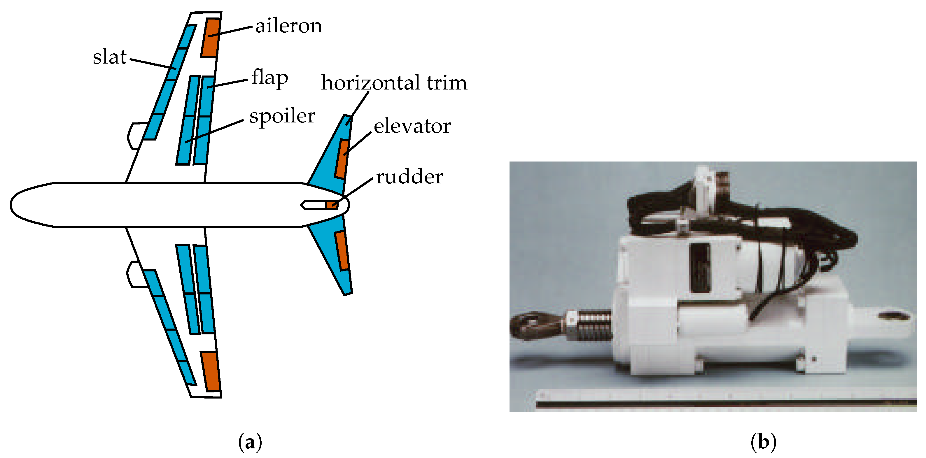
Actuators in an aircraft are typically involved in positioning of different surfaces and loads. As an example, the flight control surfaces of a typical commercial aircraft are shown in
Figure 1a. Primary flight control surfaces are responsible for controlling the pitch (controlled by elevators), roll (controlled by ailerons) and yaw (controlled by rudder). The aircraft dynamics is assisted by the secondary control surfaces also shown in the same figure. All these surfaces are positioned by actuators. Actuators are also involved in landing gear movement. The different nozzles and guide vanes within the engine are positioned by actuators.
EMAs, as opposed to hydraulic variants, have the advantage of faster control dynamics, easy integration, diagnostics and monitoring, and easy maintenance [
11,
15]. At the same time, EMA’s are susceptible to jamming [
16]. Currently, EMA’s are being utilized in thrust vector control in launchers [
17,
18]. EMA’s are also evaluated for primary control surfaces [
14,
19,
20], secondary flight controls [
21,
22] and landing gear steering [
23]. A photograph of an aileron EMA is shown in
Figure 1b.
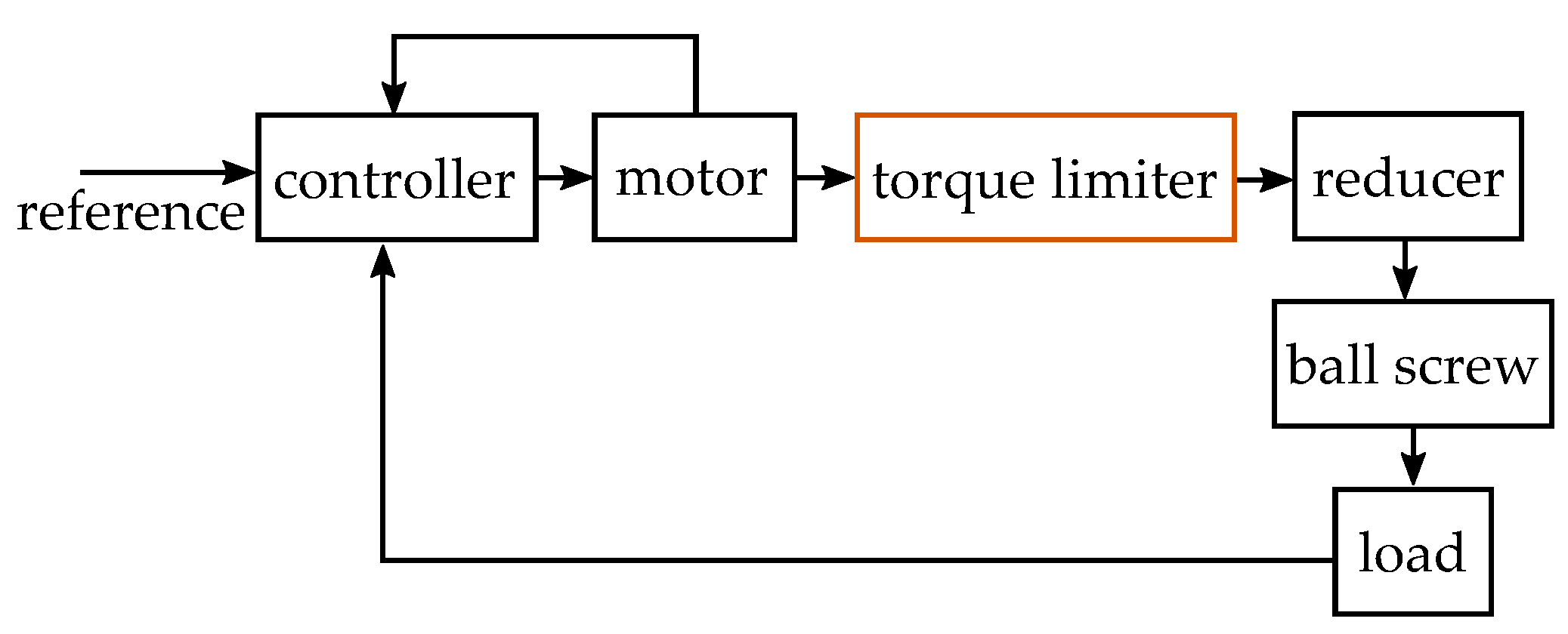
A typical EMA configuration is shown in
Figure 2. The motor controller receives reference input from the flight controller and provides correct voltage and current to the motor. The motor then drives a speed reducer, and also provide feedback to the motor controller. The rotation of the reducer is converted to linear movement by the ball screw assembly. Finally, output of the ball screw drives the load. Position feedback from the load can be integrated for closed-loop control.
The reduction mechanism in actuators minimizes the mass and volume of the motor. It also increases the equivalent inertia of the motor seen at the load end. Considering reduction ratio of
n and ball-screw lead of
l m/rev, the reflected inertia of the motor on the load end is:
where
is motor inertia. Large reduction ratios typically encountered in such actuators result in equivalent mass much higher than actual load mass [
7]. For example, a motor inertia of
with reduction of 5 and ball lead of 2 mm/rev produces equivalent mass of over 12 tons. Any fast acceleration or deceleration demanded by the load would result in very large inertial forces in the drive train and eventual breakage. Fast movement of load is required for end-stops or to give way to sudden external disturbance. It is important to limit the forces by incorporating a torque or force limiter as shown in the same Figure [
7,
15].
Ideally, the torque limiter should be as close to the disturbance as possible. Disturbance are usually in the load (sudden stops or external force) or ball screw (jamming) [
7]. Torques near the load tend to be large, leading to large size of the torque limiter. Further, inertia contributed by the motor tend to be large compared to inertia of the reducer. Therefore, typically the torque limiter is placed after the electric motor [
7]. Integration of torque limiter with the electric motor can potentially reduce size and mass of the drivetrain. Such integration options are investigated in
Section 5.
3. Classification of Torque Limiters
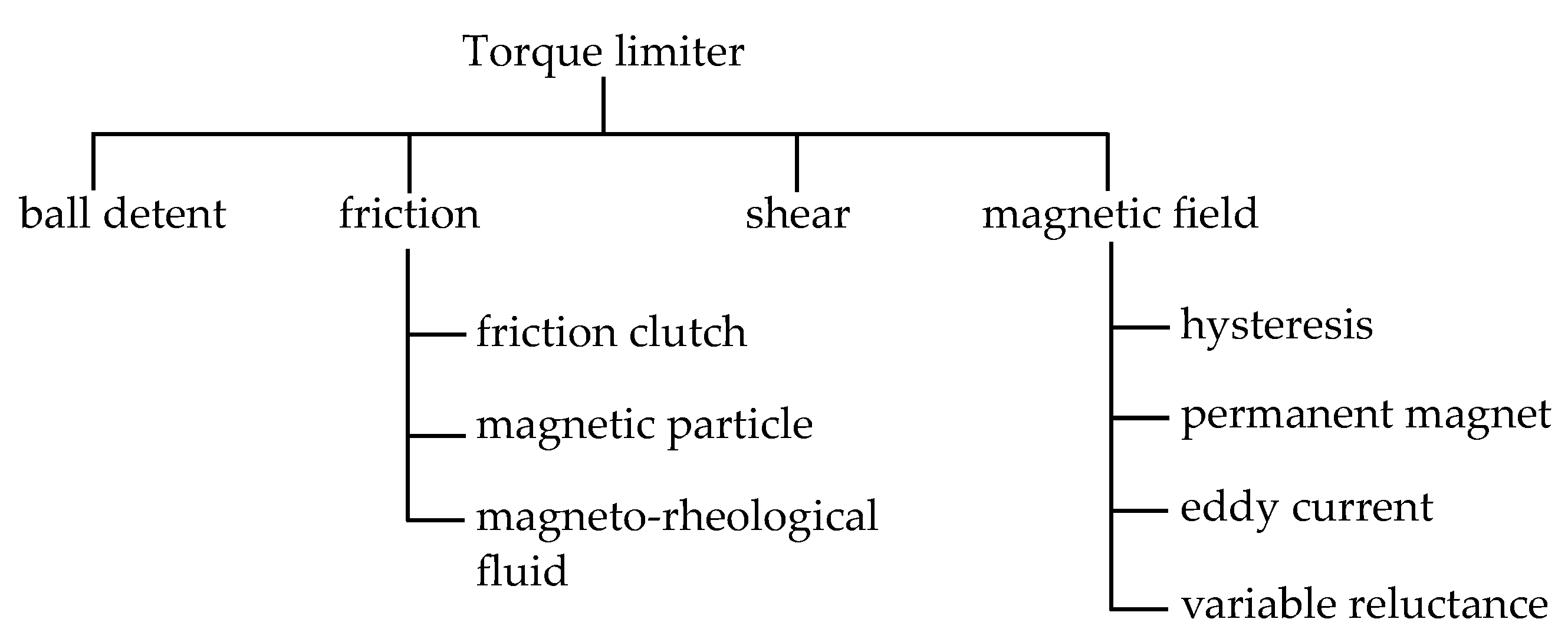
Torque limiters can be classified according to principle of torque transfer from input to output shaft.
Figure 3 shows the types of torque limiters. In principle, any torque transfer or coupler mechanism which allows precise control of maximum torque transmission can be utilized as torque limiter.
The first type of torque limiters rely on detent mechanism. An applied normal force is converted to tangential force using the mechanical profile of a groove. Commonly available ball detent or ratcheting type torque limiter utilize this principle.
The next type of torque limiter rely on friction or viscous force between two surfaces to transfer torque. Commonly available friction clutch is an example. The torque transfer mechanism can be viscosity in a liquid, in case of magneto-rheological (MR) fluid clutches.
The torque can be limited by mechanical shearing or breakage of a link between the two shafts. This forms another category of torque limiters, as shown in the same figure.
Another class of torque limiters utilize the magnetic field for torque transmission. The various types of non-contact magnetic couplers belong to this category. Magnetic field can be created by either permanent magnets or coils. The force on the output shaft can be realized by reluctance principle, magnetic alignment, induced currents or magnetic hysteresis principle.
4. Detailed Description
In the following sections, each type of torque limiter is described in more details.
4.1. Ball Detent Mechanism
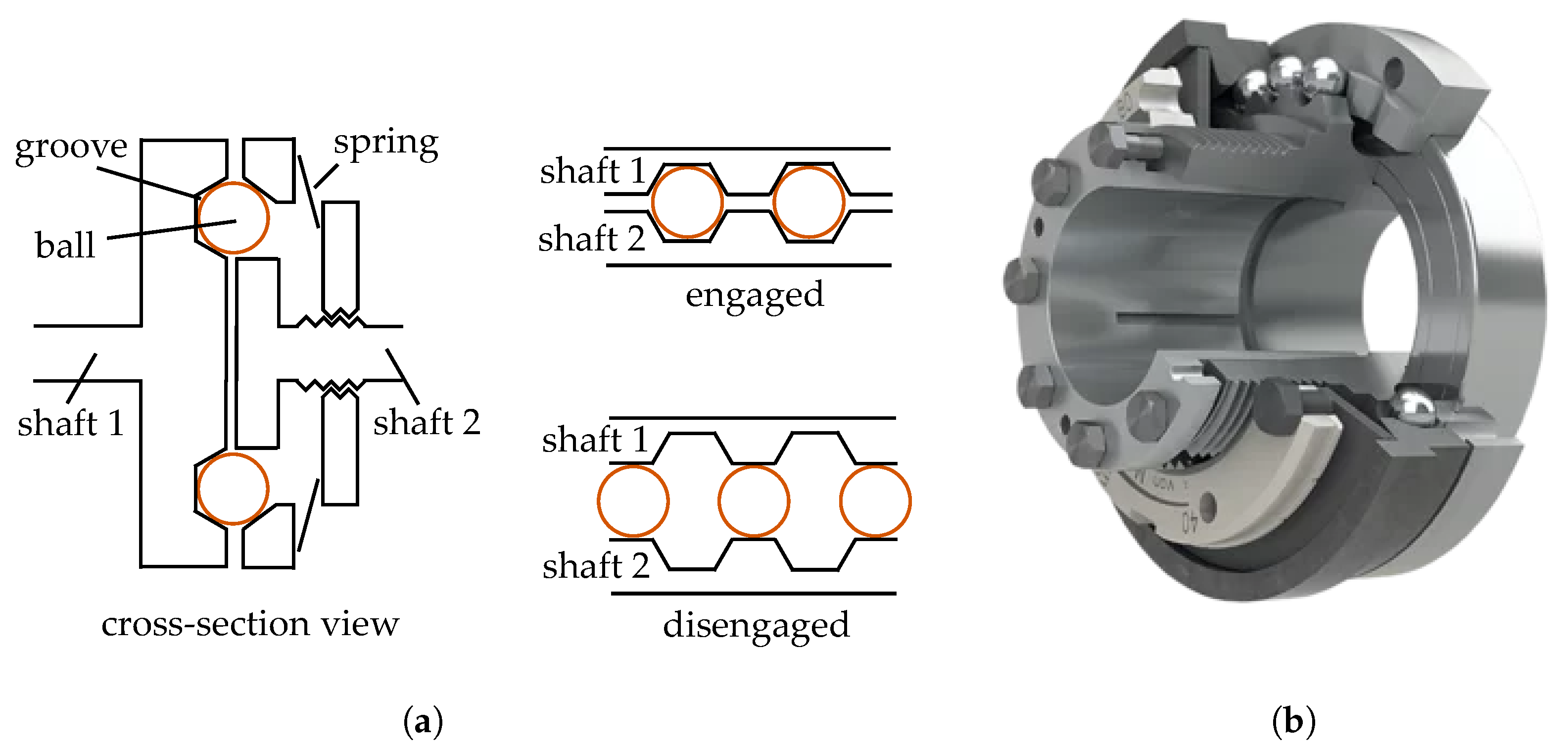
This is a common type of mechanical torque limiter and available commercially [
24,
25]. These are also referred as ratcheting type or ball and cam type torque limiters. The drive side engages with the driven side using a series of balls or rollers. These balls are placed in a small groove or indentation, as shown in
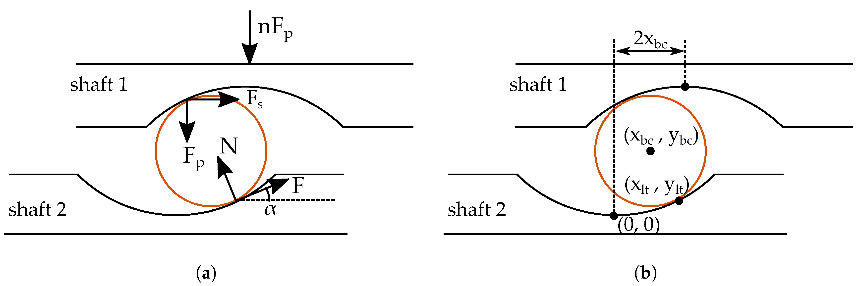
Figure 4. Spring force normal to the indentation is applied, such that a minimum tangential force or torque is required to dis-engage. Normal force can be changed to vary the limit torque. The axial movement during dis-engagement is often used to operate a limit switch.
The torque
due to each ball element can be obtained following the approach in [
27]. An enlarged view of the groove and the ball is shown in
Figure 5a. Referring to the figure, normal force experienced by each ball is
such that total normal force applied is
. Here
n refers to number of balls. Considering force and moment equilibrium condition, the normal force
and tangential force
can be related as:
where
denotes slope of the groove. The torque transmitted
is therefore:
where
is distance of the balls from the shaft rotation axis.
Considering the balls to be positioned far away from centre of rotation (i.e.,
is large compared to groove and ball dimensions), then the relative angular displacement
between the two shafts can be obtained as:
where
is ball radius. Other terms are as defined in
Figure 5b.
denote centre of the ball, and
denote point of contact between the lower ring and ball.
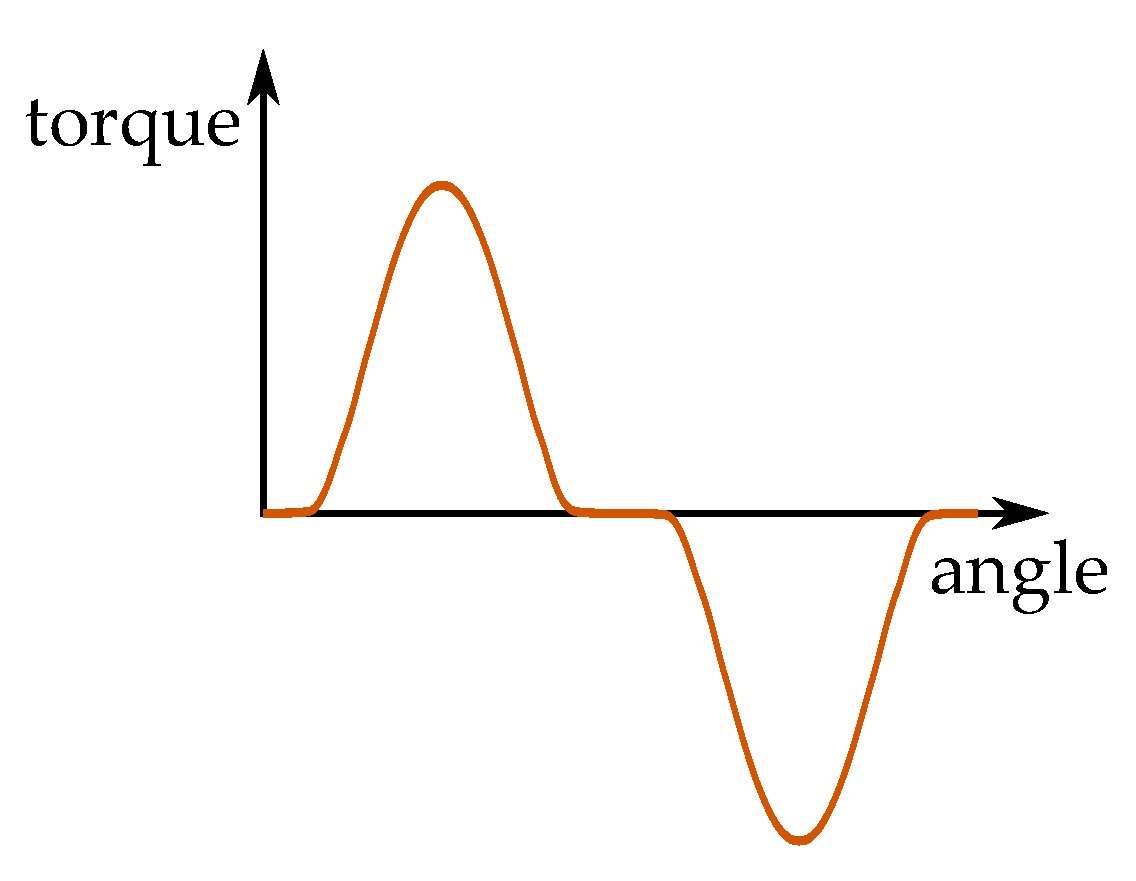
Once the balls disengage (i.e., the balls come out of the groove), the torque transmitted decreases. The balls can re-engage again with the next groove or indentation. Representative torque
vs. angle
between the shaft is shown in
Figure 6. The profile will depend on the groove profile as well as nature of normal force. Re-engagement of balls with the indentations can be synchronous (i.e., once every complete rotation) or some other angle, depending on the indentation placement [
28]. During continuous slipping, the average torque transmitted will be near zero, with large ripple.
In some variants, after any overload, re-engagement must be triggered separately. In [
29,
30], another type of rolling element and cam profile based self-resetting torque limiter is described for robotic application.
Ball detent torque limiters have the advantages of low cost and high torque-to-weight ratio. On the other hand, they can not be operated with continuous slip, and subject to mechanical wear.
4.2. Friction Clutch
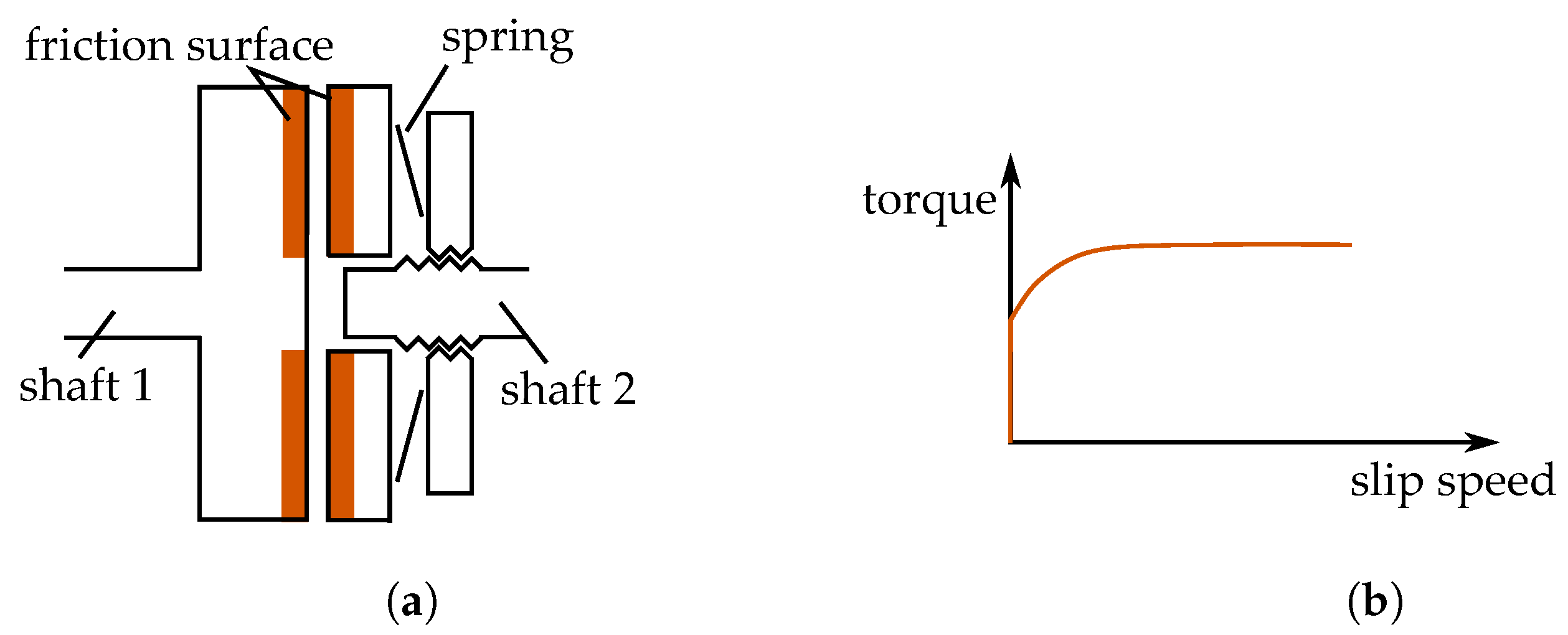
In this type, friction is used to engage the input and output shaft. When engaged, the friction surfaces on the two shafts are pressed against each other by means of springs or magnetic coils [
13]. The amount of normal force on the friction surface controls the torque transmitted. When not engaged, the friction surfaces typically have a small gap (0.2–0.3 mm), resulting in close to zero torque transmission.
In
Figure 7a, simplified cross-sectional view of spring-loaded friction torque limiter is shown. Electromagnetically actuated are also quite common. Here the friction surface is axial, like conventional clutches. The friction surface can also be a taper, as described in [
31].
Consider friction disks with inner radius
, outer radius
, friction coefficient
and total normal force applied to be
F, then torque can be obtained as below:
The torque transmitted during normal operation is limited by static friction. During slipping, the torque transmitted is governed by kinetic friction. Ideally, the torque limit is independent of slip speed and relative angle. However, differences between static and kinetic friction can lead to difference between torque limit and torque transmitted during slip. The friction coefficient can gradually decrease with time due to lubrication [
31]. The friction coefficient also depend on variety of other factors, such as slip speed, temperature, acceleration and pressure [
32]. Illustration of torque versus slip speed is shown in
Figure 7b. Slip speed is the difference between input and output shaft speed.
This type also offers good torque to weight ratio and fast dynamics [
13]. However, operation with continuous slipping will lead to wear. It is commercially available from multiple manufacturers [
24,
25].
4.3. Magnetic Particle
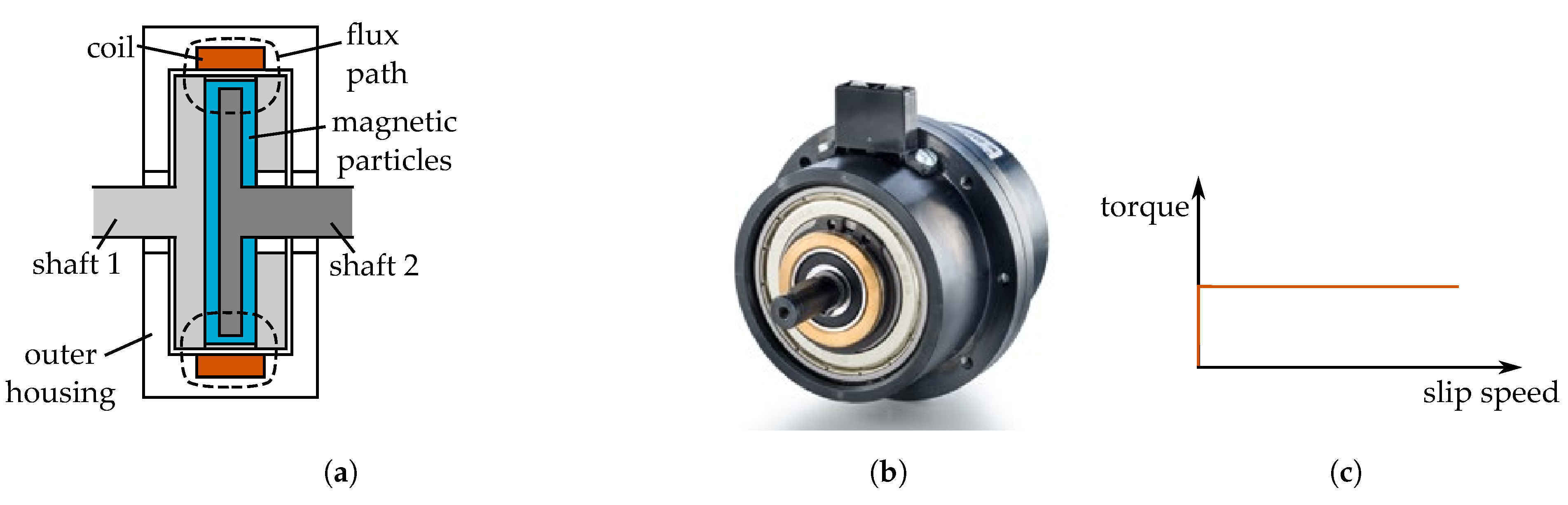
Magnetic particle (MP) clutch can also be utilized as a torque limiter. In this type, the two rotating shafts have a small gap between them. This gap is filled by small ferromagnetic particles. A coil is placed such that it creates a magnetic field which links the input and output shaft through the gap. When the coil is excited, the particles align with the field. This links the input and output shaft, thereby transmitting torque.
A sectional view is shown in
Figure 8a. In this example, a stationary coil on the housing creates the magnetic field. The two disks connected to input shaft form the two poles of a magnet. The two poles surround the inner disk connected to output disk. The space between the disks is filled with fine iron particles or magnetic particles. The particles have typical size in tens of microns [
33]. A commercially available magnetic particle clutch is shown in
Figure 8b [
34].
The torque transmitted
by the clutch depends on the shear stress
of the magnetic particles [
35]. Considering a uniform shear stress on both sides of a disk with inner radius
and outer radius
, then:
where
r denotes radial distance and
denotes infinitesimal small area considered for integration. The shear stress depend almost linearly on the applied magnetic field [
33]. It also depend on a number of other factors such as volume fraction of the particles, distance between the rotating disks and normal force. Note that, shear stress of magnetic particles does not depend on shear rate, i.e., the torque is nearly independent of slip speed [
36]. Typical achievable value of
is in the order of 10 kilo pascal (kPa) at about 1 T field [
36]. Illustrative torque versus slip speed characteristics is shown in
Figure 8c.
MP clutches are available commercially [
13,
37]. Their torque to weight ratio is lower than other types of torque limiters.
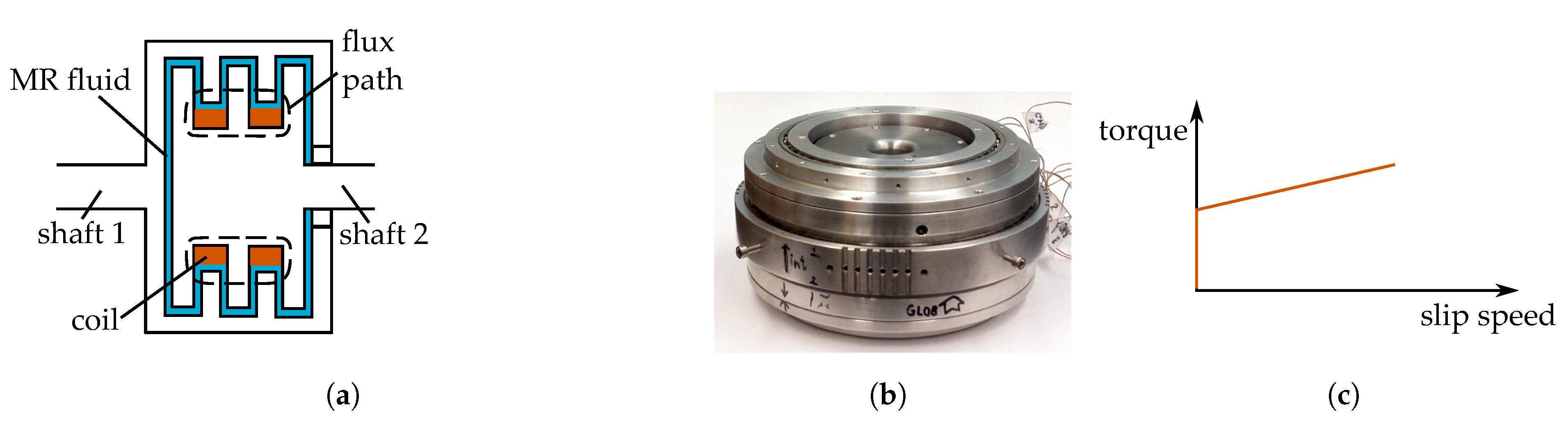
4.4. Magneto-Rheological (MR) Fluid
Operation principle of MR fluid clutch is close to magnetic particle clutch. The gap between input and output shaft is filled by MR fluid. MR fluid comprises of a carrier medium (e.g., oil, water) and micron-sized ferromagnetic particles. The maximum torque is limited by the shear stress of the MR fluid. Like magnetic particles, the particles in the fluid medium also tend to align with external magnetic field, increasing the shear stress [
38].
Illustration of MR fluid clutch is shown in
Figure 9a. The coil creates a magnetic field. The input and output shaft are arranged in a sandwich structure. The space between these disks is filled with MR fluid. When the coil is excited, the increased shear stress in the fluid creates a drag force or torque on the output shaft. The transmitted torque is limited and controllable, therefore MR fluid clutch can be used as torque limiter. A prototype MR-fluid based clutch for robotic manipulator application is shown in
Figure 9b [
39].
In
Figure 9a, only a coil generates the magnetic field. Permanent magnets, in combination with coils, can also produce a controlled B-field. In fact, MR fluid can be potentially used in all the magnetic field based torque limiters (i.e., hysteresis, permanent magnet, eddy current and variable reluctance) to increase torque density. The same comment can be made for magnetic particles as well.
Like magnetic particles, the shear stress of MR fluids have a magnetic field dependent component. Unlike magnetic particles, the shear stress
also depend on shear rate [
40]:
where
is magnetic field
B dependent component and
is shear rate dependent component. Quantity
denote viscosity and
denote shear rate. Shear rate is related to MR-fluid gap
g, relative speed between the shafts
and the radial location
r [
38]:
Usually shear stress of tens of kPa in moderate field strength is achievable, which can be enhanced by pressure [
41].
The torque limit depends on geometry and is similar to magnetic particle clutch. For a disk-like structure with inner and outer radius of
and
, (
6) can be used. Due to shear rate dependence, the torque increases with slip. This is illustrated in
Figure 9c.
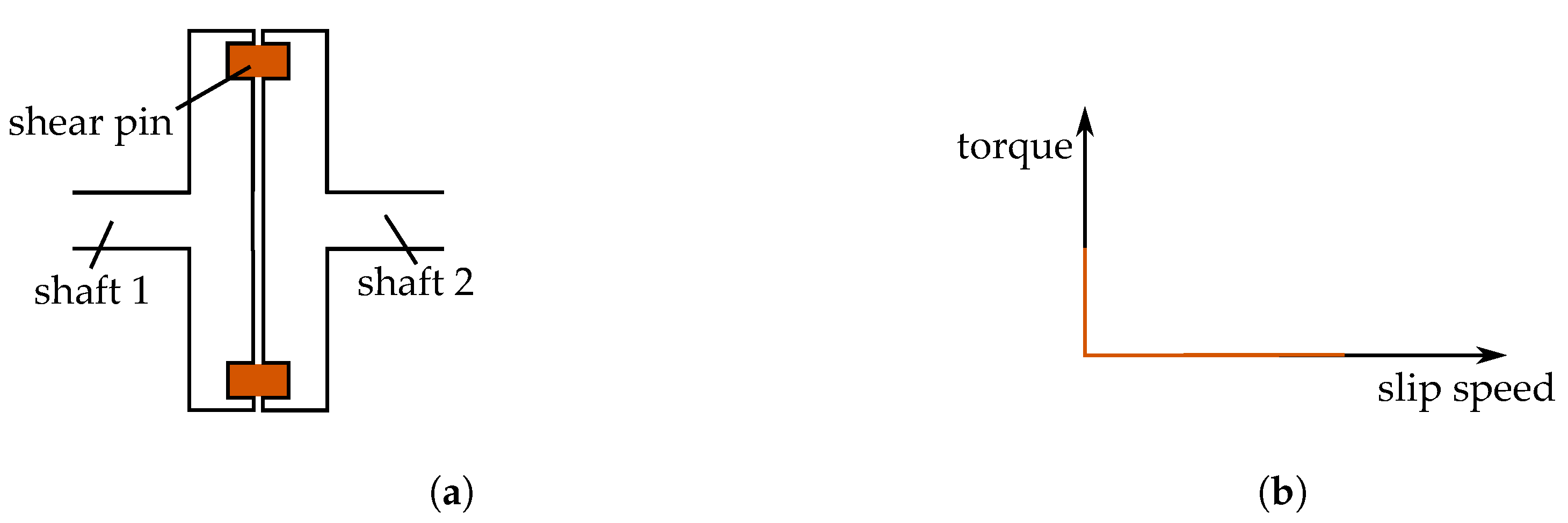
4.5. Shear
In shear pin type of torque limiter, a pin connects the input and output shaft. It fractures or shears on exceeding a torque limit. The output shaft then separates from the input shaft. To re-engage, the shear pin is replaced.
Figure 10a shows illustration of such a coupler.
The torque transmitted is limited by the shear pins. The limit torque
is given by:
where
n is number of pins,
R is radial distance of pins from center of rotation and
is shear force required to fracture each pin. Different shear pins may be used to change the torque rating.
Once the limit torque is reached, the input and output shaft will separate. Thus, during slip zero torque will be transmitted. Torque versus slip speed is shown in
Figure 10b. This kind of torque limiter is available commercially [
25,
42]. It also requires manual intervention and physical access to re-engage, and thus deemed unsuitable for actuator application.
4.6. Magnetic Hysteresis
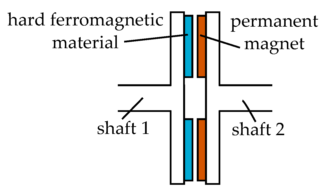
In hysteresis type of torque limiters, the input shaft has permanent magnets (PM) attached. The PM generate a rotating magnetic field inside. The output shaft has hard ferromagnetic material (HFM). The rotating magnetic field induces field in the HFM. The induced field interacts with the PM field to generate torque [
43]. Principle of operation is close to hysteresis motor.
In
Figure 11, sectional view of hysteresis torque limiter is shown. In this example, the inner shaft has the PMs, along with a small back-iron to carry the PM field. The output shaft is outer rotor, which has a hysteresis ring. There is small air-gap between input and output shaft. Typically, strong rare-earth PM is used, such as NdFeB. The hysteresis material is a hard magnetic material with wide hysteresis loop, such as AlNiCo.
The induced field in the hysteresis ring lags the rotating field generated by the PM by a small angle. The maximum torque
depends on the amount of hysteresis as follows [
43]:
where
p is number of pole pairs,
V is volume of hysteresis element, and
B and
H are the magnetic field quantities inside the hysteresis element.
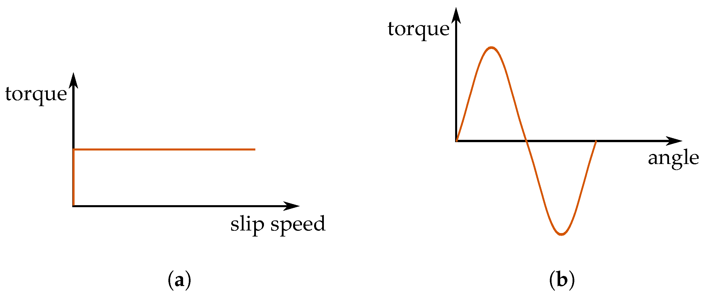
The torque transmitted versus slip speed profile is shown in
Figure 12a. The output torque is almost constant till zero slip speed (i.e., input and output shaft speed are same). At large slips, there can be small increase in torque due to eddy current. During normal operation, the load speed increases smoothly till zero slip or synchronous speed. At synchronous speed, the hysteresis material behaves like a permanent magnet and the torque limiter operates like a permanent magnet synchronous type. The angle between the input and output shaft changes to match load torque, as shown in
Figure 12b.
Analysis and design of hysteresis torque limiters are similarly challenging as design of hysteresis motors. Efforts have been made to incorporate models of magnetic hysteresis [
44], and more recently on post-processing results of magneto-static analysis [
43].
The value of limit torque can be controlled by changing amount of overlap between the permanent magnets and the HFM. In some variant, external field winding current can modulate the torque transmitted [
45].
Hysteresis torque limiters are available commercially [
24,
45]. They have low torque ripple and are mechanical wear free. However, they have low torque density.
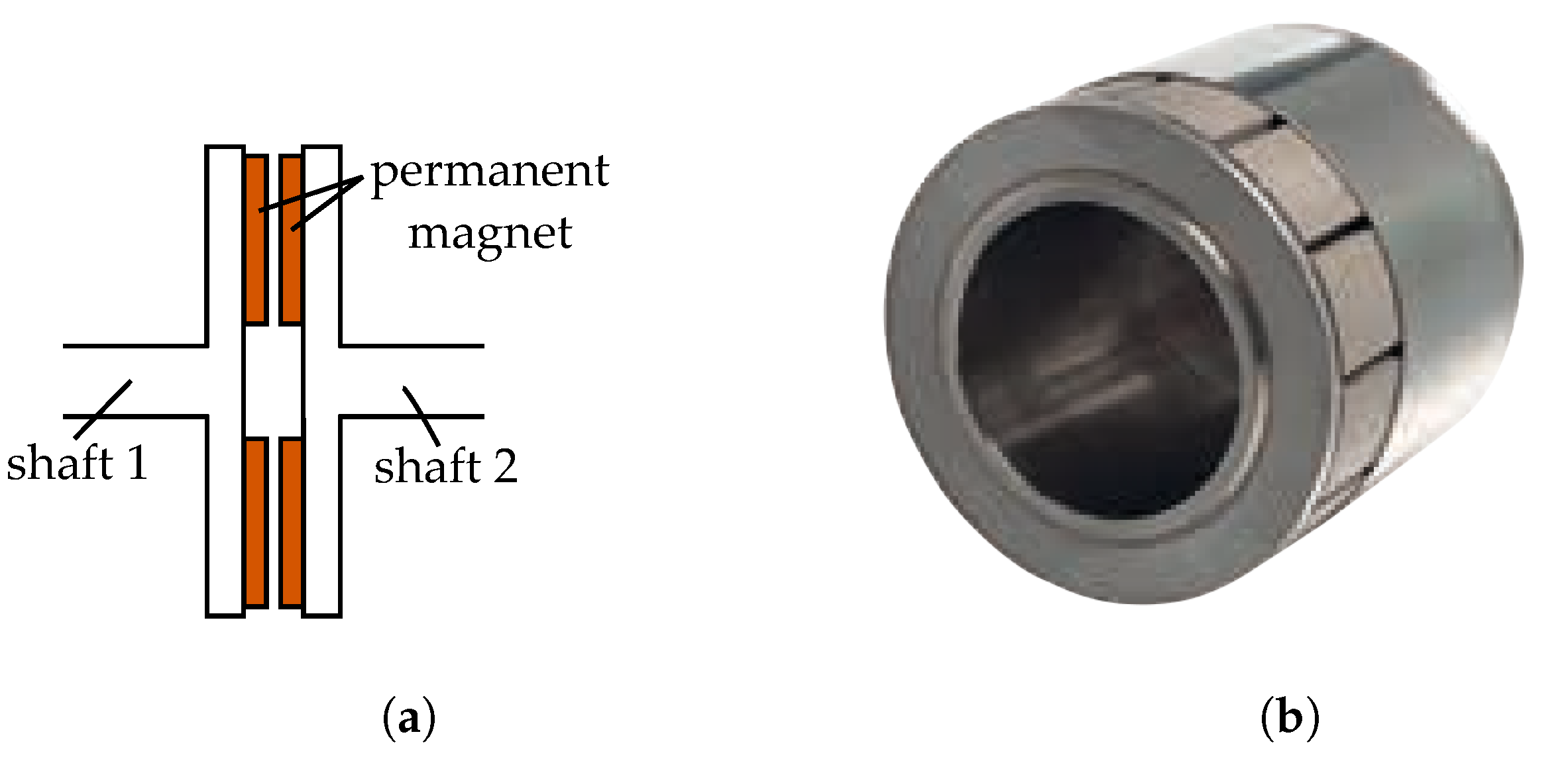
4.7. Permanent Magnet
Permanent magnet couplers can be used as torque limiter. This is a non-contact type. PMs are mounted on the input and output shafts. Opposite poles of magnets tend to align, which leads to torque on output shaft. The maximum output torque is limited by the magnetic force on the magnets. Its operation is similar to permanent magnet electric machine.
Figure 13a shows a sectional view of a axial type of PM based torque limiter. A representative assembled view of a radial type of PM coupling is shown in
Figure 13b [
46]. Alternate poles are arranged side by side in one shaft. The other shaft also has alternate poles. Opposite poles on the two shafts align at no load. During loading, there will be a small angular displacement between the magnets. In [
47], it is shown that the torque varies approximately sine of the electrical angle
between the magnets:
where
is the maximum possible torque or the pull-out torque. This is same as torque vs. angle characteristics of hysteresis torque limiter at synchronous speed, shown earlier in
Figure 12b. Pull-out torque depends on geometry and PM field. It also shows that during continuous slipping, ideally no average torque is transmitted, and large ripple torque will be present. However, there will be small torque due to eddy currents.
In the axial type of PM torque limiter, large amount of axial force will be present. Axial force depends on cosine of the angle between the magnets, apart from other parameters [
47]. Radial type of PM torque limiter are also available [
25]. In axial flux type, the maximum torque transmitted can be easily changed by varying the airgap. In radial type, the overlap between the input and output magnets can be changed to vary the maximum transmitted torque.
The airgap between the shafts can be used to completely seal one of the shafts (e.g., in a pressurized or corrosive environment). Due to the presence of magnets, their application is limited to up-to 300
[
25].
Considering small angular difference between the two shafts, the torque transmitted is proportional to the angle difference. The coupler acts like additional torsional stiffness. During transient, this may lead to oscillation in speed [
48].
Permanent magnet couplers (which can be used as torque limiter) are available commercially [
25].
4.8. Eddy Current
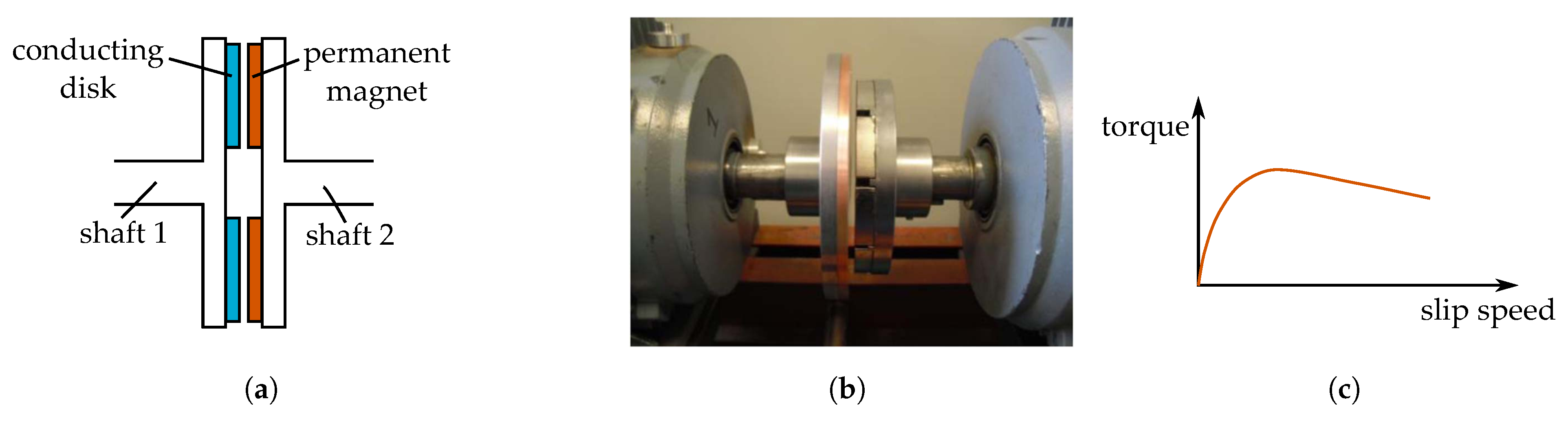
Eddy current couplers also offer over-load protection and can be used as torque limiters. This is another non-contact type torque limiter, where the force is generated due to induced currents. One of the shafts carry permanent magnets. The other shaft has a conducting plate. If there is any relative motion between the two, currents will be induced in the conducting plate which generates torque.
In
Figure 14a construction of axial flux type eddy current coupler is shown. Magnets are attached/glued on one shaft. The flux from the magnet intersects a conducting copper disk on the other shaft through an air-gap. Two back-iron parts complete the flux path. A photograph is shown in
Figure 14b.
The principle of operation is similar to induction machines. The torque depends on slip-speed, as shown in
Figure 14c. Typically, the operation is limited to low slips, to prevent overheating of the coupler. Near zero slip, the torque is proportional to difference between the shaft speeds
and
as below [
48]:
where constant
k depends on permanent magnet field, material properties and geometry.
Since, no torque is transmitted at zero slip, eddy current coupler is not suitable for applications requiring positional accuracy. On the other hand, the dissipative mechanism of eddy currents acts like a viscous damping. It is potentially useful for vibration isolation [
48]. Being non-contact, eddy current couplers are also useful in applications requiring containment [
50].
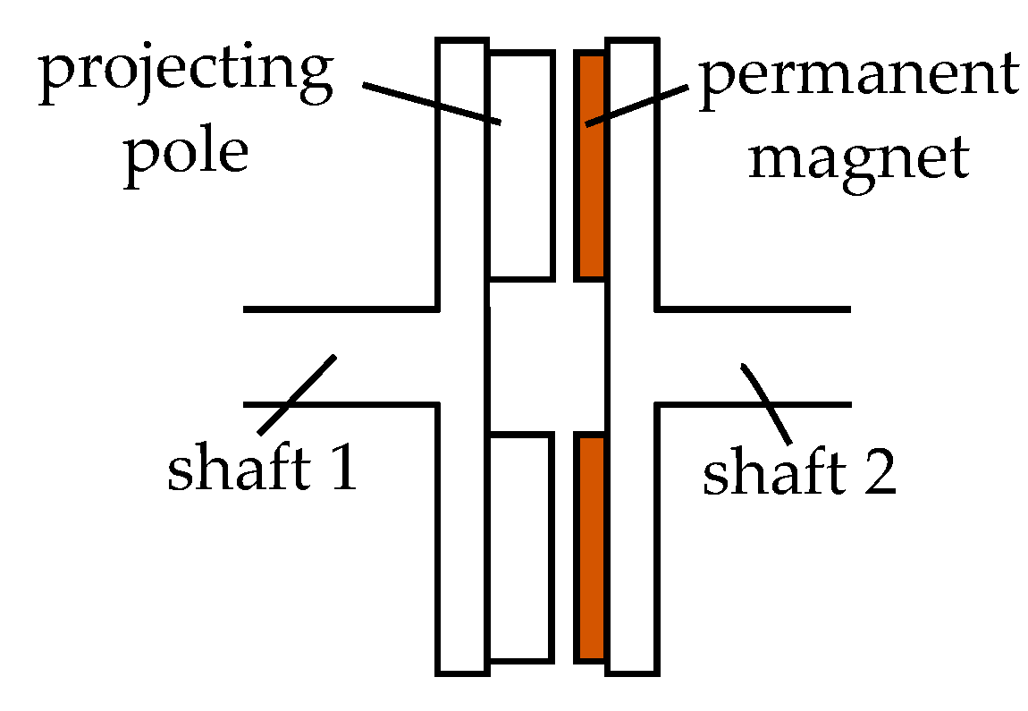
4.9. Variable Reluctance
Variable reluctance coupler has permanent magnets on one of the shafts. The other shaft has same number of projections made of ferromagnetic material (e.g., iron). The projections or poles tend to align with the magnets, to minimize reluctance. This generates torque. The maximum torque transmitted is limited by the construction and magnetic field. Therefore, variable reluctance coupler can also be used as torque limiter.
Construction of such a coupler is shown in
Figure 15. The torque produced depend on the angle difference as well as speed difference between the two shafts [
51]:
where
B is the damping coefficient. The first term in the equation denotes the reluctance torque. Note that it varies as sine of twice the electrical angle between the shafts, unlike permanent and hysteresis coupler. The second term denotes torque generated by the induced eddy current in iron during slip. It has lower torque density than permanent magnet based coupler, but also has higher damping during transient.
4.10. Others
In [
52], a roller based torque limiter is described for robotic application. The transmitted torque depends on the roller angle, geometry, friction coefficient and normal force applied to the rollers.
Further, torque limiter functionality can be potentially implemented as part of control of the electric machine driving the EMA. This is referred as electronic torque limiter. A more detailed discussion is presented in
Section 6.
4.11. Comparative Evaluation
The commercially available torque limiters are evaluated in
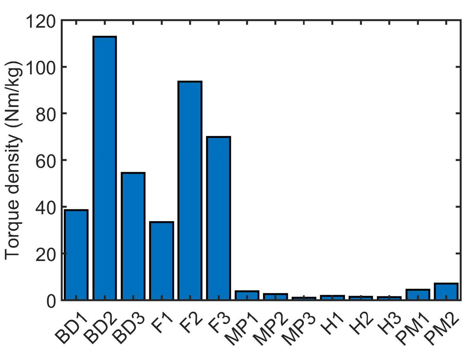
Table 1. As mentioned earlier, shear type is excluded since it requires manual replacement of shear pins to re-engage. In aerospace application, size and weight are very important. For the considered torque of 10 Nm, the envelope dimensions and weight are compared in the table. Multiple manufacturers for the same type of torque limiter are listed, to remove any potential bias. It is clear that both ball detent and friction type have good torque density. However, they suffer from wear. Ball detent type has large torque ripple, as mentioned earlier. The non-contact hysteresis type has least torque density among all, but has the advantage of smooth operation and low torque ripple. Permanent magnet type has reasonable torque density and no wear, but also has torque oscillation. A comparison of torque densities is shown in
Figure 16.
A qualitative comparison of the torque limiters is presented in
Table 2. As mentioned earlier, both ball detent and friction type offer good torque density. Electrical actuation of torque limiter and continuous variation of the limit torque value provide flexibility to the designer. The drive train can be tested automatically for correct operation. Typically most, except ball detent and PM type, can be configured for electrical actuation.
Complexity and reliability are other important factors for torque limiter selection. Complexity refers to how the torque limiter is constructed, sealing requirement, coil arrangement etc. Hysteresis and PM type are less complex in construction than others. The number of components are considered in reliability, lower component count is preferred. Ball detent have many components such as multiple balls and springs. Hysteresis and PM type have the least number of components.
Finally, slip behaviour and high-speed capability is also listed in the same table. Actuators machines typically have speeds in the range of 5 kprm to 20 krpm. Only friction type is commercially available in these speeds. It is possible for hysteresis and PM type to have high speed capability. Overall, friction and PM type torque limiters are most suitable options for actuator application.
5. Integration of Torque Limiter
Integration of power electronic components [
64,
65,
66] within the electric machine is being actively researched. Integration of passive components such as inductors has been explored in [
67,
68,
69,
70]. Integration of electric machine rotor with the impeller of fan [
71] and propeller [
72] are also investigated. All these provide significant savings in mass and volume. Similarly, integration of the torque limiter within the package of the electric machine can provide reduction in size and weight of the EMA. In this section, several integration configurations are explored. As an specific example of integration, a electric drive for flap positioning is considered for integration.
5.1. Electric Machine Details
The electric motor is designed to replace conventional hydraulic actuation system for flap movement in a more electric aircraft. The electric motor typically can be induction machine, switched reluctance machine or permanent magnet machine. Fault tolerance of the motor is very important in flap actuation application. The large magnetic coupling between the phases and rotor heating at low speeds reduces fault tolerant capability of induction machines. Switched reluctance machines have low mutual coupling and inherent fault tolerance. However, during fault in one phase, there can be low or zero torque at certain rotor positions. This limits application of switched reluctance machine for position actuation system such as flap, where full torque at all rotor position is desired.
PM machines have good torque capability and highest torque per unit volume among the three. They can be designed with good fault tolerance as well. A dual channel design is considered, where two sets of three phase winding are present. Each channel is connected in star, with isolated neutral and each fed by a separate power converter. Each channel is designed to provide the required torque of 3.34 Nm and power of 3.5 kW at 10,000 rpm.
An important consideration during design is drag torque during short circuit fault in one of the channels. The currents in the short circuited winding will produce a braking or drag torque. The other healthy channel is designed to overcome the drag torque and still produce the rated shaft torque of 3.34 Nm. For the design, the maximum drag torque of 0.3 Nm is considered.
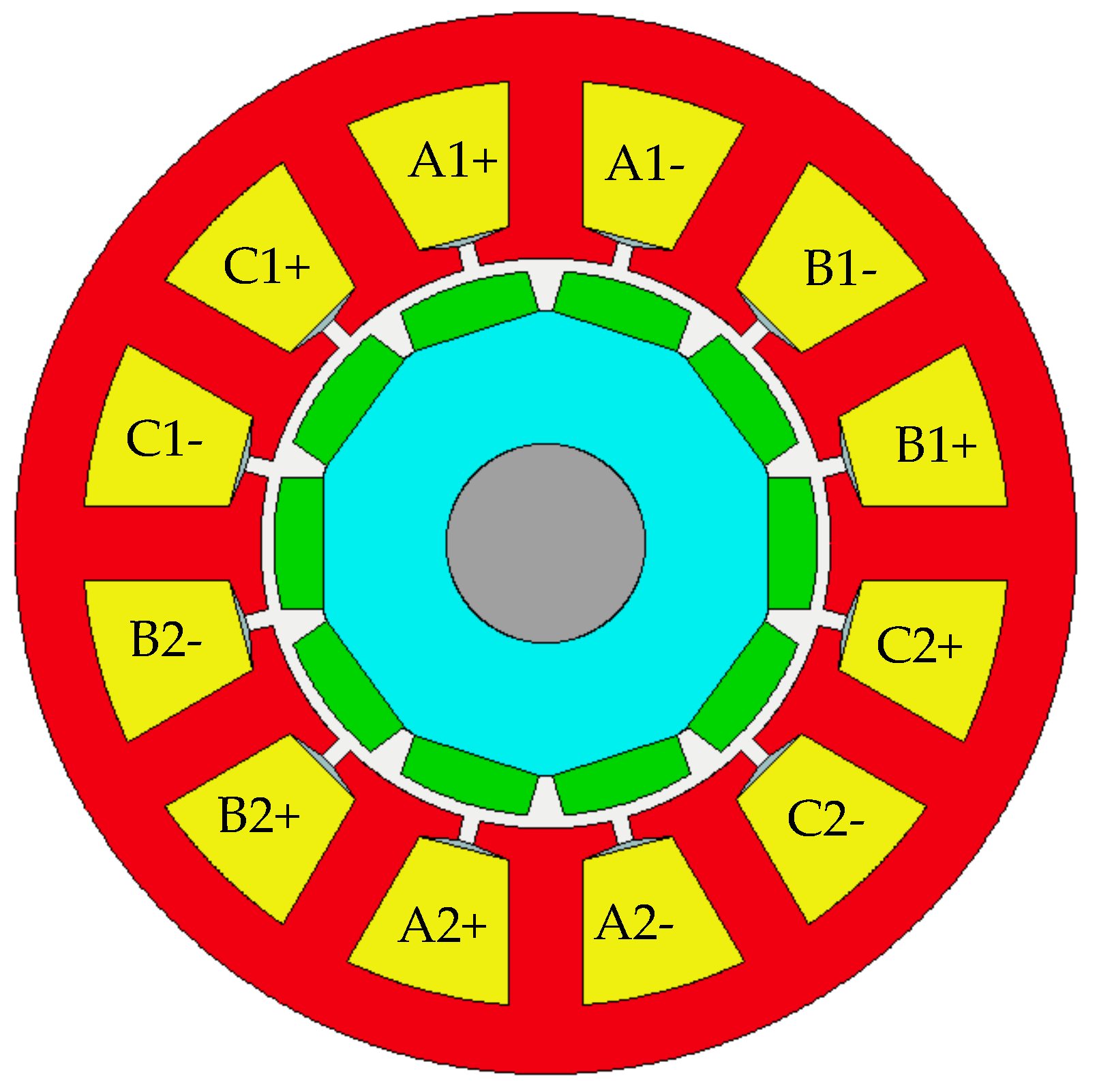
Important ratings and dimensions are provided in
Table 3. A cross-sectional view of the machine is presented in
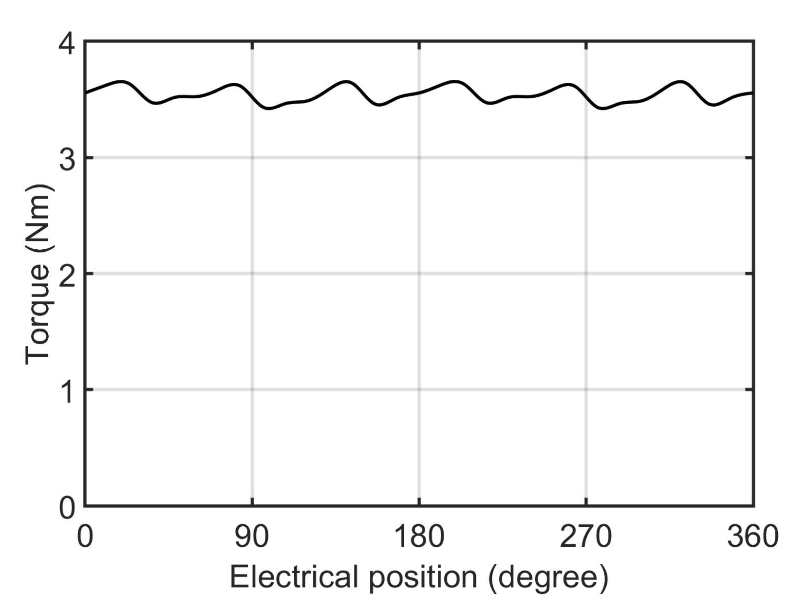
Figure 17. The three phases of channel 1 are represented by A1, B1 and C1, while phases of channel 2 are denoted A2, B2 and C2. The phases of individual channels are placed together, and isolated from the other channel. The torque plot at rated condition when one channel is operating is shown in
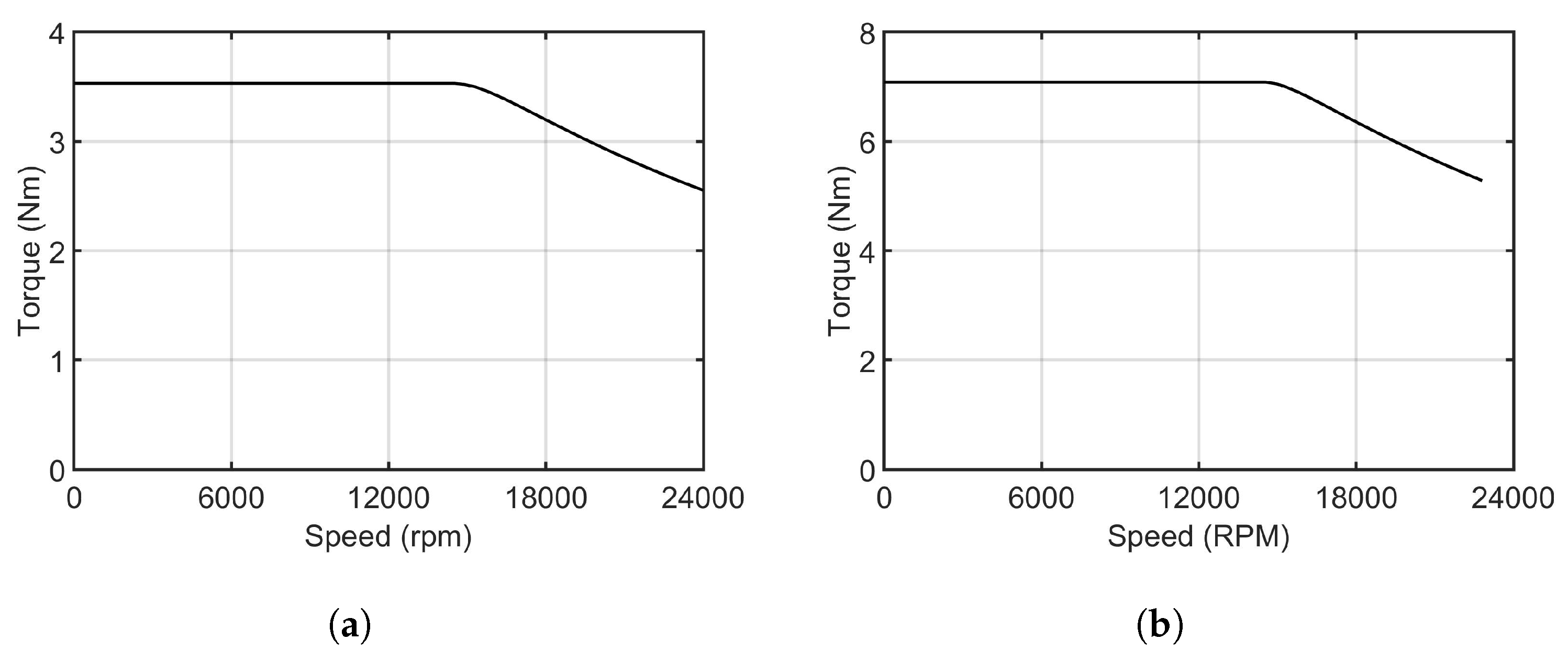
Figure 18. The average value of torque is nearly 3.6 Nm, which is equal to rated torque and maximum drag torque. Torque-speed graph with one channel and both channels operating at rated condition is shown in
Figure 19a,b.
Considering torque ripple and margin for transients, a torque limiter rating of 10 Nm is suitable for this machine, such as F3 in
Table 1.
5.2. Axially Engaging Integrated Torque Limiter
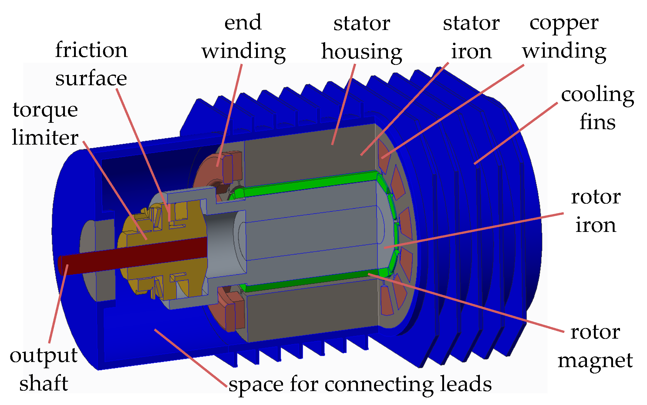
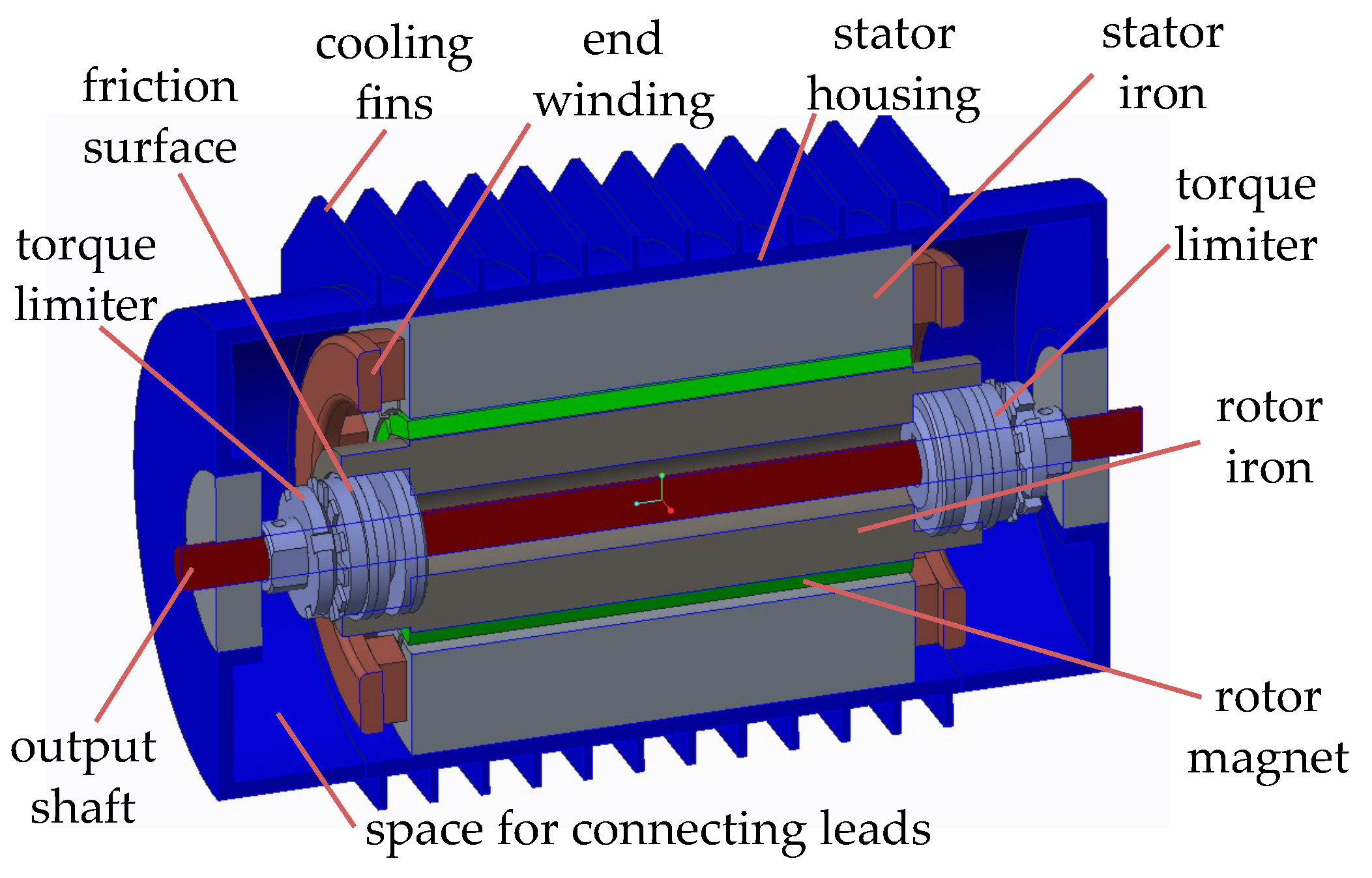
In first integration configuration, the torque limiter engages with the electric machine rotor axially. The end winding space is utilized for integration. The electric machine rotor and stator are otherwise unmodified. The integration concept is demonstrated in
Figure 20 using the commercially available torque limiter F3 in
Table 1. The rotor of the electric machine can be supported on the torque limiter by interference fit. The frictional surface, which provides torque limiting function, is axially placed. An internal chamber within the electric machine rotor is created to accommodate the torque limiter. In this example, extension of housing at one end of the machine is required to accommodate the torque limiter. The same space is used by end winding and connecting leads, as indicated in the figure.
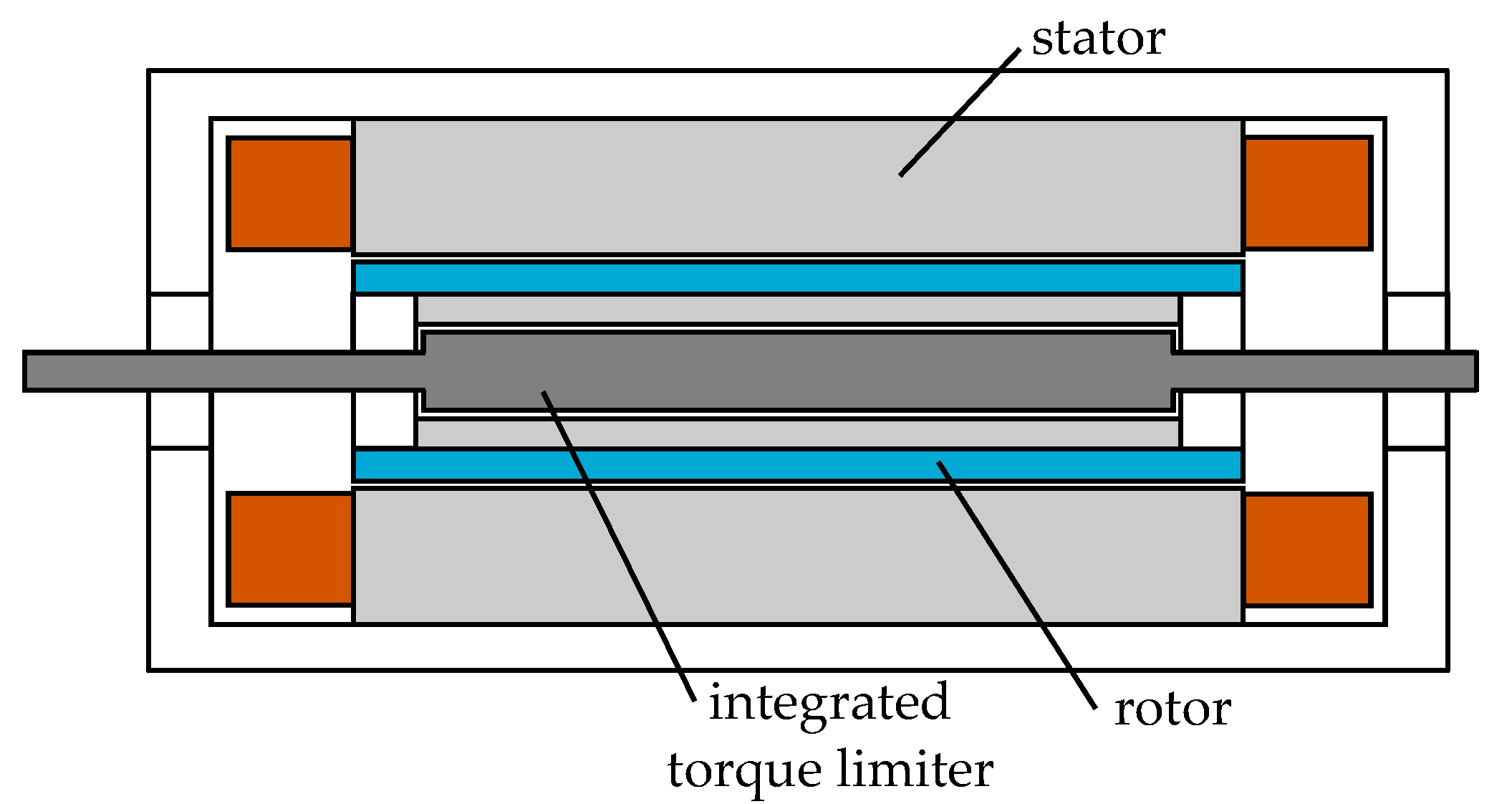
A smaller torque limiter with lower torque limit can be used on both sides of the electric machine rotor to achieve the same overall torque level. This concept is demonstrated in
Figure 21. Both end winding space are utilized for torque limiter function. The empty space between end winding and casing at one end is used by the connecting leads, empty space at other end is required to accommodate the torque limiter. Two numbers of commercially available torque limiter ComInTec 00.25 DF T1 [
58], each rated for 8 Nm, are utilized in this example. An inner shaft, which is same as output shaft, connects both the torque limiters. The electric machine rotor connects to the output shaft through the two torque limiters. This results in a more compact packaging. The overall volume of the machine package with two smaller torque limiter is 0.90 litre, compared to 0.96 litre in case of one larger torque limiter. Single torque limiter configuration occupies 6.67% more volume.
Torque limiter can fail either jammed or open. If it fails open, configuration with two torque limiter can still operate with reduced capacity. Depending on type of torque limiter, it can be more prone to jamming. In that case, one torque limiter will be more reliable.
For the axially engaging integrated torque limiter, the available space is severely limited, therefore only the high torque density torque limiters are suitable for integration. Further detailed rotor-dynamic and structural analysis is required to verify the design. Other components may be added to improve robustness.
5.3. Radially Engaging Integrated Torque Limiter
In this configuration the torque limiter engages radially with the electric machine rotor over a comparatively large surface. The torque limiter is placed in an inner rotor, which supports the electric machine rotor. For the particular machine being considered, no suitable torque limiter are commercially available. A sketch of the concept is therefore shown in
Figure 22.
Since a larger surface area is available, radial arrangement of non-contact magnetic field based torque limiter are now viable. Ball detent type torque limiter would be challenging to implement. Friction type torque limiter could be implemented, for example following the tapered design in [
31].
Such a concept for a permanent magnet type torque limiter is examined in detail in [
73]. Since, both the torque limiter and the electric machine utilize magnetic field, it is possible to share magnetic circuit and excitation source. A common magnetic circuit and PM excitation would however couple the torque limiter operation and machine operation.
5.4. Discussion
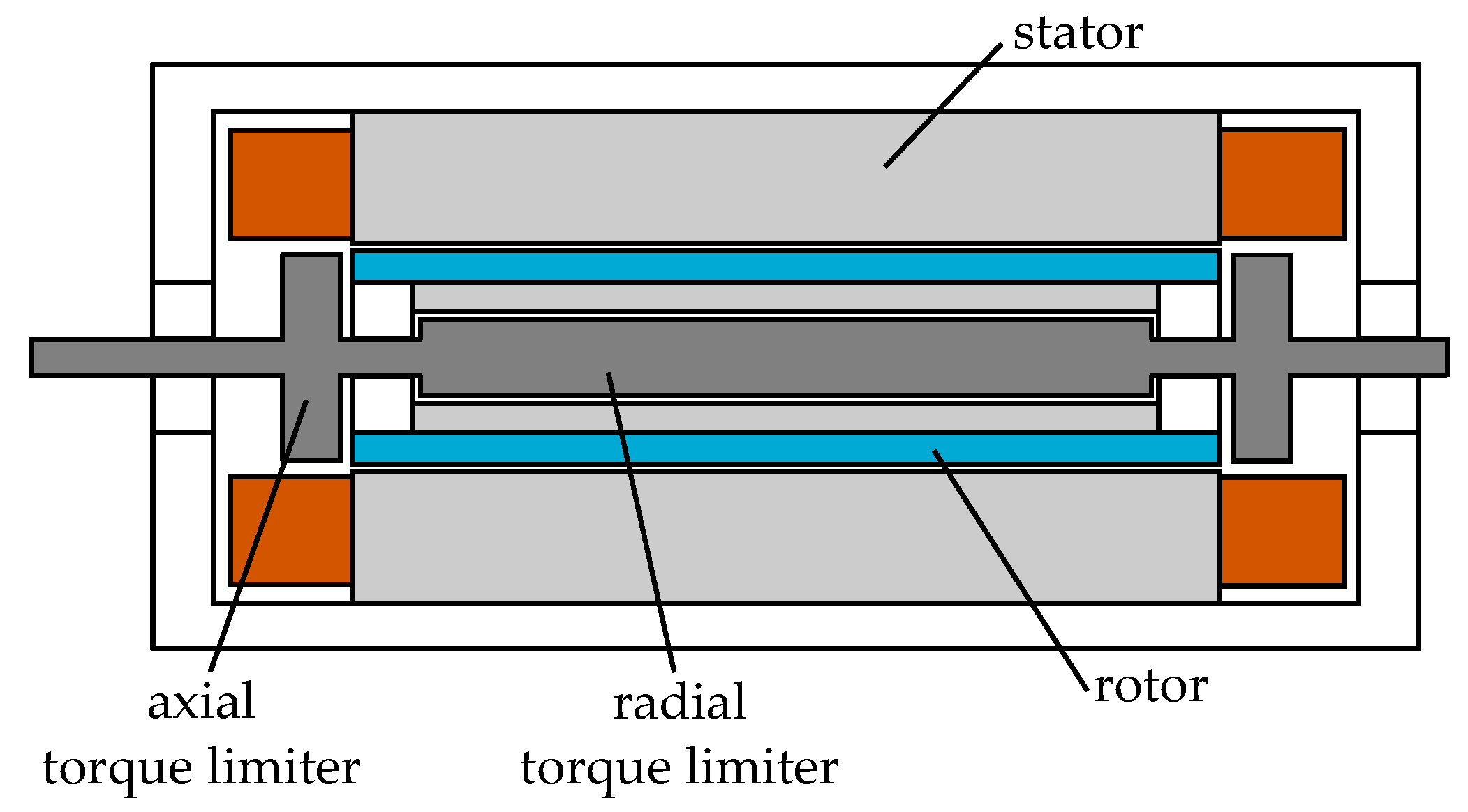
A combination of the above configurations are also viable. For example, axial torque limiters could be implemented on the end winding space, and a radial magnetic field based torque limiter within the inner rotor can be accommodated. Such a highly integrated concept is illustrated in
Figure 23. Two axial engaging torque limiters are placed in end winding space, and a radially engaging torque limiter is mounted in the inner shaft.
In all cases, high torque density of the torque limiter is essential. Application of MR fluid or magnetic particles can enhance the torque capability of magnetic field based torque limiters, further reducing the weight and inertia.
6. Electronic Torque Limiter
Instead of a physical torque limiter device disconnecting the load from the motor, another approach could be to limit the forces on shaft using motor control [
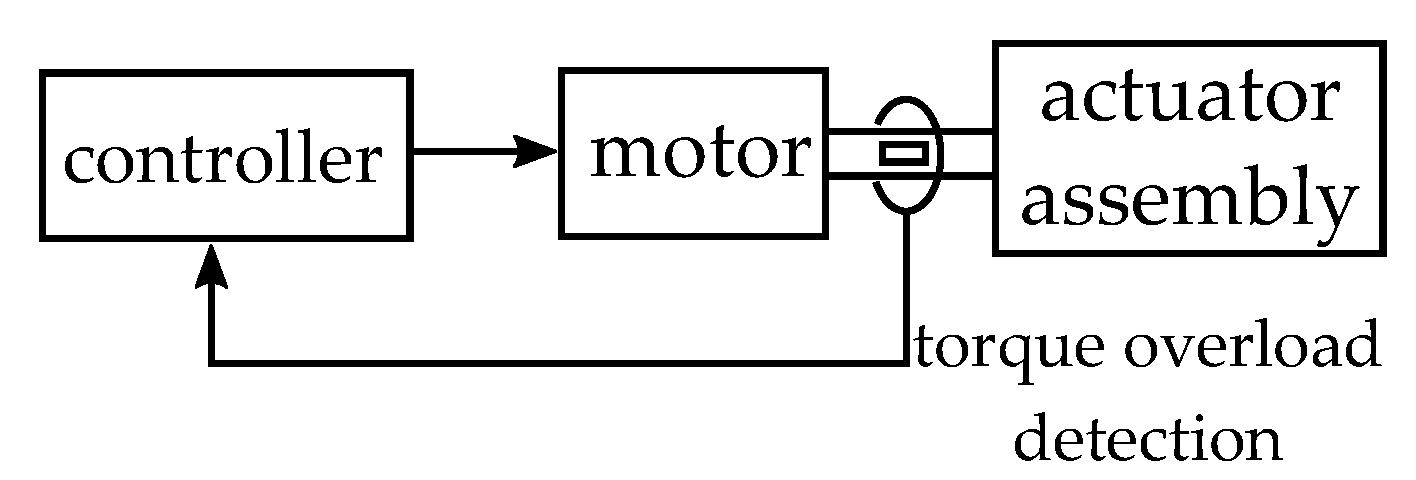
7]. The electromagnetic torque generated by the motor can assist in reducing the speed of the rotating mass in case of any jam and thereby reduce the forces experienced by the shaft. The motor controller receives feedback from the shaft during any overload, and injects large current to the motor to quickly bring the motor to standstill.
A block diagram of the scheme is shown in
Figure 24. A overload signal is generated from a shaft mounted sensor. Feedback from shaft could be obtained through strain gauges, or torsional twisting of shaft ends with respect to each other. One or multiple feedback location can be utilised to protect the shaft from large forces.
This approach has the following advantages:
No extra space required to connect a physical torque limiter
Lower mass and volume of the actuator
Lower mechanical complexity
Value of limit torque easily varied and electronically controlled
On the other hand this approach have the following disadvantages:
Requires shaft overload sensors
Large controller bandwidth required
Power converter for the motor must be capable of large transient current
Electric motor also must be capable of large peak torque
7. Conclusions
Torque limiters are an essential component of electro-mechanical actuators. In this paper, existing torque limiter technologies are reviewed. These transmit torque either due to mechanical contact or through magnetic field. Construction and principle of operation of each type are reported, along with characteristics and key equations. These characteristics can help the designer of EMA select appropriate torque limiter. While some transmit torque during slipping, others have large torque ripple and nearly zero average torque. In case of magnetic particle and hysteresis type, the torque transmitted is largely independent of slip-speed.
The commercially available limiters are evaluated for suitability in aerospace application. Mass and volume are two major constraints in EMA. Torque density of a sample of 14 different available off-the-shelf torque limiters are compared. Ball detent, friction and permanent magnet types are found to have best torque density. Further considering complexity, reliability and speed requirements, friction and permanent magnet types are found to be most suitable for EMA application.
Integration of torque limiter within the machine package is then investigated. Two configurations are demonstrated using a designed EMA electrical machine, along with suitable commercially available limiters. A fault-tolerant dual channel surface mount PM machine for flap actuation is considered, and key performance of the machine are reported. In the axial integration configuration, the torque limiter engages with rotor axially and utilizes the end winding space. It is possible to have either one limiter at one end or two limiters at both ends. It is shown that two lower rated devices at both ends can provide more compact packaging, than one higher rated. Another radial configuration is also explored, which is suitable for magnetic field based torque limiters. Finally, an option for further integration, using combination of the two integration approaches, is illustrated.
Author Contributions
Conceptualization, S.S.A., G.V. and C.G.; methodology, S.S.A. and G.V.; software, S.S.A.; validation, S.S.A., G.V., C.G. and M.B.; formal analysis, S.S.A.; investigation, S.S.A.; resources, S.S.A.; data curation, S.S.A.; writing—original draft preparation, S.S.A. and L.T.; writing—review and editing, S.S.A., G.V., C.G. and M.B.; visualization, S.S.A., L.T., A.L.R. and S.L.R.; supervision, G.V. and C.G.; project administration, G.V., C.G. and M.B.; funding acquisition, G.V., C.G. and M.B. All authors have read and agreed to the published version of the manuscript.
Funding
The work in this paper is supported by the NGHLS project (Project No. 113179) funded by Collins Aerospace, Actuation Systems, UK, and the ATI programme, a joint Government and industry investment to maintain and grow the UK’s competitive position in civil aerospace design and manufacture. The programme, delivered through a partnership between the Aerospace Technology Institute (ATI), Department for Business, Energy & Industrial Strategy (BEIS) and Innovate UK, addresses technology, capability and supply chain challenges.
Institutional Review Board Statement
Not applicable.
Informed Consent Statement
Not applicable.
Conflicts of Interest
The authors declare no conflict of interest.
References
- Wang, Y.; Nuzzo, S.; Zhang, H.; Zhao, W.; Gerada, C.; Galea, M. Challenges and Opportunities for Wound Field Synchronous Generators in Future More Electric Aircraft. IEEE Trans. Transp. Electrif. 2020, 6, 1466–1477. [Google Scholar] [CrossRef]
- Shang, Y.; Li, X.; Qian, H.; Wu, S.; Pan, Q.; Huang, L.; Jiao, Z. A Novel Electro Hydrostatic Actuator System With Energy Recovery Module for More Electric Aircraft. IEEE Trans. Ind. Electron. 2020, 67, 2991–2999. [Google Scholar] [CrossRef]
- Ni, K.; Liu, Y.; Mei, Z.; Wu, T.; Hu, Y.; Wen, H.; Wang, Y. Electrical and Electronic Technologies in More-Electric Aircraft: A Review. IEEE Access 2019, 7, 76145–76166. [Google Scholar] [CrossRef]
- Nøland, J.K.; Leandro, M.; Suul, J.A.; Molinas, M.; Nilssen, R. Electrical Machines and Power Electronics For Starter-Generators in More Electric Aircrafts: A Technology Review. In Proceedings of the IECON 2019-45th Annual Conference of the IEEE Industrial Electronics Society, Lisbon, Portugal, 14–17 October 2019; Volume 1, pp. 6994–7001. [Google Scholar] [CrossRef] [Green Version]
- Barzkar, A.; Ghassemi, M. Electric Power Systems in More and All Electric Aircraft: A Review. IEEE Access 2020, 8, 169314–169332. [Google Scholar] [CrossRef]
- Buticchi, G.; Bozhko, S.; Liserre, M.; Wheeler, P.; Al-Haddad, K. On-Board Microgrids for the More Electric Aircraft—Technology Review. IEEE Trans. Ind. Electron. 2019, 66, 5588–5599. [Google Scholar] [CrossRef] [Green Version]
- Maré, J.C. Aerospace Actuators 2: Signal-by-Wire and Power-by-Wire; John Wiley & Sons: Hoboken, NJ, USA, 2017. [Google Scholar]
- D’Andrea, M.; Di Domenico, G.; Macera, D.; Fiume, F. Electromagnetic brakes in electromechanical actuators for aerospace applications. In Proceedings of the 2020 International Symposium on Power Electronics, Electrical Drives, Automation and Motion (SPEEDAM), Sorrento, Italy, 24–26 June 2020; pp. 484–488. [Google Scholar] [CrossRef]
- Maré, J.C. Practical Considerations in the Modelling and Simulation of Electromechanical Actuators. Actuators 2020, 9, 94. [Google Scholar] [CrossRef]
- Huang, L.; Yu, T.; Jiao, Z.; Li, Y. Active Load-Sensitive Electro-Hydrostatic Actuator for More Electric Aircraft. Appl. Sci. 2020, 10, 6978. [Google Scholar] [CrossRef]
- MARÉ, J.C.; FU, J. Review on signal-by-wire and power-by-wire actuation for more electric aircraft. Chin. J. Aeronaut. 2017, 30, 857–870. [Google Scholar] [CrossRef]
- Maré, J.C. Aerospace Actuators 1: Needs, Reliability and Hydraulic Power Solutions; John Wiley & Sons: Hoboken, NJ, USA, 2016. [Google Scholar]
- Wang, Y.; Schmitz, A.; Kobayashi, K.; Lopez, J.A.A.; Wang, W.; Matsuo, Y.; Sakamoto, Y.; Sugano, S. Evaluation of Series Clutch Actuators With a High Torque-to-Weight Ratio for Open-Loop Torque Control and Collision Safety. IEEE Robot. Autom. Lett. 2018, 3, 297–304. [Google Scholar] [CrossRef]
- Jensen, S.; Jenney, G.; Dawson, D. Flight test experience with an electromechanical actuator on the F-18 Systems Research Aircraft. In Proceedings of the 19th DASC. 19th Digital Avionics Systems Conference. Proceedings (Cat. No.00CH37126), Philadelphia, PA, USA, 7–13 October 2000; Volume 1, pp. 2E3/1–2E310. [Google Scholar] [CrossRef]
- Qiao, G.; Liu, G.; Shi, Z.; Wang, Y.; Ma, S.; Lim, T.C. A review of electromechanical actuators for More/All Electric aircraft systems. Proc. Inst. Mech. Eng. Part C J. Mech. Eng. Sci. 2018, 232, 4128–4151. [Google Scholar] [CrossRef] [Green Version]
- Garcia, A.; Cusido, I.; Rosero, J.; Ortega, J.; Romeral, L. Reliable electro-mechanical actuators in aircraft. IEEE Aerosp. Electron. Syst. Mag. 2008, 23, 19–25. [Google Scholar] [CrossRef]
- Dée, G.; Vanthuyne, T.; Potini, A.; Pardos, I.; De Crombrugghe, G. Electromechanical Thrust Vector Control Systems for the Vega-C launcher. In Proceedings of the 8th European Conference for Aeronautics and Space Sciences (EUCASS 2019), Madrid, Spain, 1–4 July 2019; 2019. [Google Scholar] [CrossRef]
- Tutt, G.; Jansen, J. Dynamics of the Apollo electromechanical actuator. J. Spacecr. Rocket. 1968, 5, 541–546. [Google Scholar] [CrossRef]
- Derrien, J.C.; Tieys, P.; Senegas, D.; Todeschi, M. EMA Aileron COVADIS Development. In Aerospace Technology Conference and Exposition; SAE International: Warrendale, PA, USA, 2011. [Google Scholar] [CrossRef]
- Norton, W.J. Advanced Electromechanical Actuation System (EMAS), Flight Test; Technical Report; TEST WING (4950TH): Wright-Patterson AFB, OH, USA, 1986. [Google Scholar]
- Bennett, J.; Mecrow, B.; Jack, A.; Atkinson, D.; Sheldon, S.; Cooper, B.; Mason, G.; Sewell, C.; Cudley, D. A prototype electrical actuator for aircraft flaps and slats. In Proceedings of the IEEE International Conference on Electric Machines and Drives, San Antonio, TX, USA, 15 May 2005; pp. 41–47. [Google Scholar] [CrossRef]
- Villani, M.; Tursini, M.; Fabri, G.; Castellini, L. High Reliability Permanent Magnet Brushless Motor Drive for Aircraft Application. IEEE Trans. Ind. Electron. 2012, 59, 2073–2081. [Google Scholar] [CrossRef]
- Bennett, J.; Mecrow, B.; Atkinson, D.; Maxwell, C.; Benarous, M. A fault tolerant electric drive for an aircraft nose wheel steering actuator. In Proceedings of the 5th IET International Conference on Power Electronics, Machines and Drives (PEMD 2010), Brighton, UK, 19–21 April 2010; pp. 1–6. [Google Scholar] [CrossRef] [Green Version]
- Torque Limiters. Available online: https://www.mayr.com/synchronisation/documentations/img_402_v09_en_18_02_2020.pdf (accessed on 17 May 2021).
- Drive Technology. Available online: https://www.ktr.com/fileadmin/ktr/media/Tools_Downloads/kataloge/DriveTechnology.pdf (accessed on 17 May 2021).
- The Backlash-Free, Load Disconnecting Safety Clutch. Available online: https://www.mayr.com/en/products/clutches/safety-clutches/load-separating/torque-limiter/eas-compact~478 (accessed on 4 June 2021).
- Takaoka, S.; Yamada, H.; Hirose, S. Snake-like active wheel robot ACM-R4.1 with joint torque sensor and limiter. In Proceedings of the 2011 IEEE/RSJ International Conference on Intelligent Robots and Systems, San Francisco, CA, USA, 25–30 September 2011; pp. 1081–1086. [Google Scholar] [CrossRef]
- TT-SI Safety Clutch. Available online: https://ttindustrial.com/content/catalog/TT-SI-safety-clutch.pdf (accessed on 18 May 2021).
- Lee, W.; Choi, J.; Kang, S. Spring-Clutch: A safe torque limiter based on a spring and CAM mechanism with the ability to reinitialize its position. In Proceedings of the 2009 IEEE/RSJ International Conference on Intelligent Robots and Systems, St. Louis, MO, USA, 10–15 October 2009; pp. 5140–5145. [Google Scholar] [CrossRef]
- Hong, S.; Choi, J.; Lee, W.; Kang, S.; Lee, H. Development of a safe manipulator using spring-clutches. In Proceedings of the 2013 13th International Conference on Control, Automation and Systems (ICCAS 2013), Gwangju, Korea, 20–23 October 2013; pp. 1811–1814. [Google Scholar] [CrossRef]
- Lin, C.Y.; Jo, P.C.; Tseng, C.K. New compliance-mechanism design for small companion robots. J. Intell. Robot. Syst. 2011, 64, 585–601. [Google Scholar] [CrossRef]
- Pica, G.; Cervone, C.; Senatore, A.; Lupo, M.; Vasca, F. Dry dual clutch torque model with temperature and slip speed effects. Intell. Ind. Syst. 2016, 2, 133–147. [Google Scholar] [CrossRef] [Green Version]
- Chen, K.; Tian, Y.; Shan, L.; Jiang, J. Transient response of sheared magnetic powder excited by a stepwise magnetic field and its comparison with ER and MR fluids. Smart Mater. Struct. 2013, 22, 097001. [Google Scholar] [CrossRef]
- Magnetic Particle Clutches, Brakes and Controllers. Available online: https://www.kendrion.com/fileadmin/user_upload/Downloads/Brochures_and_Flyers/Industrial_Brakes/brochure-magnet-particle-clutches-and-brakes-202001.pdf (accessed on 7 June 2021).
- Mikhaeil-Boules, N. Design analysis of electromagnetic particle clutch. In Proceedings of the 1994 IEEE Industry Applications Society Annual Meeting, Denver, CO, USA, 2–6 October 1994; Volume 2, pp. 357–360. [Google Scholar] [CrossRef]
- Chen, K.; Tian, Y.; Shan, L.; Zhang, X.; Meng, Y. The rheological properties of magnetic field excited magnetic powders sheared between two parallel plates. Smart Mater. Struct. 2013, 22, 115036. [Google Scholar] [CrossRef]
- Permanent Magnet and Magnetic Particle Clutches and Brakes. Available online: https://www.warnerelectric.com/-/media/Files/Literature/Brand/warner-electric/catalogs/p-1316-we.ashx (accessed on 7 June 2021).
- Moghani, M.; Kermani, M.R. Design and development of a hybrid Magneto-Rheological clutch for safe robotic applications. In Proceedings of the 2016 IEEE International Conference on Robotics and Automation (ICRA), Stockholm, Sweden, 16–21 May 2016; pp. 3083–3088. [Google Scholar] [CrossRef]
- Pisetskiy, S.; Kermani, M. High-performance magneto-rheological clutches for direct-drive actuation: Design and development. J. Intell. Mater. Syst. Struct. 2021, 32, 2582–2600. [Google Scholar] [CrossRef]
- Jolly, M.R.; Bender, J.W.; Carlson, J.D. Properties and Applications of Commercial Magnetorheological Fluids. J. Intell. Mater. Syst. Struct. 1999, 10, 5–13. [Google Scholar] [CrossRef]
- Tao, R. Super-strong magnetorheological fluids. J. Phys. Condens. Matter 2001, 13, R979–R999. [Google Scholar] [CrossRef]
- Torque Overload Release Couplings. Available online: https://www.ahrinternational.com/PDF_catalogues/Kop-Flex/Torque_Overload_Release_Coupling.pdf (accessed on 9 June 2021).
- Gallicchio, G.; Nardo, M.D.; Palmieri, M.; Cupertino, F. Analysis, Design and Optimization of Hysteresis Clutches. IEEE Open J. Ind. Appl. 2020, 1, 258–269. [Google Scholar] [CrossRef]
- Padilha, J.B.; Kuo-Peng, P.; Sadowski, N.; Batistela, N.J. Vector hysteresis model associated with FEM in a hysteresis motor modeling. In Proceedings of the 2016 IEEE Conference on Electromagnetic Field Computation (CEFC), Miami, FL, USA, 13–16 November 2016; p. 1. [Google Scholar] [CrossRef]
- Electromagnetic Slip Clutches. Available online: https://www.sdp-si.com/PDFS/Electromagnetic-Slip-Clutches-Metric.pdf (accessed on 25 May 2021).
- Permanent Magnetic System Technology. Available online: https://www.e-group.de/downloads/d.php?id=393440ba88ff63278da0b98a857aa272&file=dst_image_en_0520.pdf (accessed on 9 June 2021).
- Lubin, T.; Mezani, S.; Rezzoug, A. Simple Analytical Expressions for the Force and Torque of Axial Magnetic Couplings. IEEE Trans. Energy Convers. 2012, 27, 536–546. [Google Scholar] [CrossRef] [Green Version]
- Lubin, T.; Fontchastagner, J.; Mezani, S.; Rezzoug, A. Comparison of transient performances for synchronous and eddy-current torque couplers. In Proceedings of the 2016 XXII International Conference on Electrical Machines (ICEM), Lausanne, Switzerland, 4–7 September 2016; pp. 695–701. [Google Scholar] [CrossRef] [Green Version]
- Lubin, T.; Rezzoug, A. Steady-State and Transient Performance of Axial-Field Eddy-Current Coupling. IEEE Trans. Ind. Electron. 2015, 62, 2287–2296. [Google Scholar] [CrossRef] [Green Version]
- Li, W.; Zhang, G.; Ai, L.; Liu, G.; Gao, Z.; Liu, H. Characteristics Analysis at High Speed of Asynchronous Axial Magnetic Coupler for Superconducting Flywheel Energy Storage System. IEEE Trans. Appl. Supercond. 2019, 29, 1–5. [Google Scholar] [CrossRef]
- Lubin, T.; Colle, A. Simulation analysis and experimental evaluation of the transient behaviour of a reluctance magnetic coupling. IET Electr. Power Appl. 2020, 14, 391–397. [Google Scholar] [CrossRef] [Green Version]
- Fukui, W.; Kobayashi, F.; Kojima, F.; Nakamoto, H.; Maeda, T.; Imamura, N.; Sasabe, K.; Shirasawa, H. Development of multi-fingered universal robot hand with torque limiter mechanism. In Proceedings of the 2009 35th Annual Conference of IEEE Industrial Electronics, Porto, Portugal, 3–5 November 2009; pp. 2205–2210. [Google Scholar] [CrossRef] [Green Version]
- EAS-Compact. Available online: https://www.mayr.com/produkte/dokumentationen/k_490_v17_en_12_08_2020.pdf (accessed on 11 June 2021).
- SYNTEX®-NC Operating/Assembly Instructions. Available online: https://www.ktr.com/fileadmin/ktr/media/Manuals/46110en000000.pdf (accessed on 7 July 2021).
- SKP Torque Limiter with Pure Keyway Connection. Available online: https://www.rw-couplings.com/products/precision-couplings/safety-couplings/skp/ (accessed on 11 June 2021).
- ROBA®-Slip Hubs. Available online: https://www.mayr.com/produkte/dokumentationen/k_123_v14_en_16_01_2017.pdf (accessed on 11 June 2021).
- Overload Protection Clutches. Available online: https://www.crossmorse.com/images/specifications/torque_limiters.pdf (accessed on 11 June 2021).
- Friction Torque Limiter. Available online: https://www.comintec.com/download/cataloghi/sezioni/torque_limiters/DF_EN.pdf (accessed on 11 June 2021).
- EM Magnetic Particle Clutch. Available online: https://ogura-clutch.com/products.php?category=5&product=28&sort=3 (accessed on 14 June 2021).
- Magnetic Particle Clutch C70. Available online: https://placidindustries.com/d/?h=79729d0 (accessed on 14 June 2021).
- ROBA-Contitorque. Available online: https://www.mayr.com/produkte/dokumentationen/k_150_v09_gb_16_05_2012.pdf (accessed on 11 June 2021).
- Magnetic Brakes and Magnetic Clutches. Available online: https://www.magnetictech.com/hysteresis-brakes/ (accessed on 14 June 2021).
- Permanent Magnetic Coupling PMK. Available online: https://www.tea-hamburg.de/katalog/img/cms/Datenbl%C3%A4tter/Datenblatt%20Permanent-Magnet-Rutschkupplungen.pdf (accessed on 14 June 2021).
- Abebe, R.; Vakil, G.; Lo Calzo, G.; Cox, T.; Lambert, S.; Johnson, M.; Gerada, C.; Mecrow, B. Integrated motor drives: State of the art and future trends. IET Electr. Power Appl. 2016, 10, 757–771. [Google Scholar] [CrossRef] [Green Version]
- Hennen, M.D.; Niessen, M.; Heyers, C.; Brauer, H.J.; De Doncker, R.W. Development and Control of an Integrated and Distributed Inverter for a Fault Tolerant Five-Phase Switched Reluctance Traction Drive. IEEE Trans. Power Electron. 2012, 27, 547–554. [Google Scholar] [CrossRef]
- Wu, S.; Tian, C.; Zhao, W.; Zhou, J.; Zhang, X. Design and Analysis of an Integrated Modular Motor Drive for More Electric Aircraft. IEEE Trans. Transp. Electrif. 2020, 6, 1412–1420. [Google Scholar] [CrossRef]
- Rocca, A.L.; Khowja, M.R.; Vakil, G.; Gerada, C.; Wheeler, P.; Yan, L. Thermal Design of an Integrated Inductor for 45kW Aerospace Starter-Generator. In Proceedings of the 2020 IEEE Transportation Electrification Conference Expo (ITEC), Chicago, IL, USA, 23–26 June 2020; pp. 703–708. [Google Scholar] [CrossRef]
- Khowja, M.R.; Gerada, C.; Vakil, G.; Patel, C.; Odhano, S.; Walker, A.; Wheeler, P. Novel Permanent Magnet Synchronous Motor With Integrated Filter Inductor, Using Motor’s Inherent Magnetics. IEEE Trans. Ind. Electron. 2021, 68, 5638–5649. [Google Scholar] [CrossRef]
- Khowja, M.R.; Gerada, C.; Vakil, G.; Abebe, R.; Odhano, S.; Patel, C.; Wheeler, P. Novel Motor-Shaped Rotational Inductor for Motor Drive Applications. IEEE Trans. Ind. Electron. 2020, 67, 1844–1854. [Google Scholar] [CrossRef]
- Khowja, M.R.; Vakil, G.; Gerada, C.; Patel, C.; Odhano, S.; Wheeler, P. Integrated Motor Drive: Mass and Volume Optimization of the Motor with an Integrated Filter Inductor. Energies 2021, 14, 4564. [Google Scholar] [CrossRef]
- Wu, S.T.; Huang, P.W.; Chang, T.W.; Jiang, I.H.; Tsai, M.C. Application of Magnetic Metal 3-D Printing on the Integration of Axial-Flow Impeller Fan Motor Design. IEEE Trans. Magn. 2021, 57, 8201205. [Google Scholar] [CrossRef]
- Hao, Z.; Shuanbao, J.; Dong, W.; Gongbao, W.; Pengfei, H. Design and Analysis of the Integrated Motor Cooling System for Shaftless Propeller. IEEE Access 2019, 7, 174573–174582. [Google Scholar] [CrossRef]
- Atallah, K.; Calverley, S.D.; Howe, D. A Brushless Permanent Magnet Motor With Integrated Torque-Limiter. IEEE Trans. Magn. 2007, 43, 2498–2500. [Google Scholar] [CrossRef]
Figure 1.
Flight control surfaces and example EMA (
a) Primary (red) and secondary (blue) flight control surfaces (
b) Photograph of a primary flight control (aileron) EMA [
14]. ©IEEE. Reprinted, with permission, from Jensen, S.; Jenney, G.; Dawson, D. Flight test experience with an electromechanical actuator on the F-18 Systems Research Aircraft. In Proceedings of the 19th Digital Avionics Systems Conference Proceedings, Philadelphia, PA, USA, 7–13 October 2000.
Figure 2.
Typical block diagram of aerospace actuator.
Figure 2.
Typical block diagram of aerospace actuator.
Figure 3.
Torque limiter classification based on principle of operation.
Figure 3.
Torque limiter classification based on principle of operation.
Figure 4.
Ball detent type torque limiter (
a) Illustration of cross-section (
b) 3-dimensional view [
26]. Reproduced with permission from Mayr, The Backlash-Free, Load Disconnecting Safety Clutch.
Figure 4.
Ball detent type torque limiter (
a) Illustration of cross-section (
b) 3-dimensional view [
26]. Reproduced with permission from Mayr, The Backlash-Free, Load Disconnecting Safety Clutch.
Figure 5.
Torque in ball detent torque limiter: (a) Forces in each ball element (b) Position of different elements.
Figure 5.
Torque in ball detent torque limiter: (a) Forces in each ball element (b) Position of different elements.
Figure 6.
Torque vs. angle characteristics of ball detent type torque limiter.
Figure 6.
Torque vs. angle characteristics of ball detent type torque limiter.
Figure 7.
Friction type torque limiter: (a) Cross-section diagram (b) Representative torque vs. slip speed characteristics.
Figure 7.
Friction type torque limiter: (a) Cross-section diagram (b) Representative torque vs. slip speed characteristics.
Figure 8.
Magnetic particle type clutch: (
a) Cross-section (
b) Assembled view [
34]. Reproduced with permission from Kendrion, Magnetic particle clutches, brakes and controllers. (
c) Ideal torque vs. slip speed characteristics.
Figure 8.
Magnetic particle type clutch: (
a) Cross-section (
b) Assembled view [
34]. Reproduced with permission from Kendrion, Magnetic particle clutches, brakes and controllers. (
c) Ideal torque vs. slip speed characteristics.
Figure 9.
Of magneto-rheological (MR) fluid clutch: (
a) Illustration (
b) Photograph of a MR-fluid clutch for robotic application [
39] (
c) Torque vs. slip speed characteristics.
Figure 9.
Of magneto-rheological (MR) fluid clutch: (
a) Illustration (
b) Photograph of a MR-fluid clutch for robotic application [
39] (
c) Torque vs. slip speed characteristics.
Figure 10.
Shear pin type of torque limiter: (a) Illustration (b) Ideal torque vs. slip speed characteristics.
Figure 10.
Shear pin type of torque limiter: (a) Illustration (b) Ideal torque vs. slip speed characteristics.
Figure 11.
Cross-section of hysteresis torque limiter.
Figure 11.
Cross-section of hysteresis torque limiter.
Figure 12.
Torque characteristics of hysteresis torque limiter (a) vs. slip speed and (b) vs. electrical angle at synchronous speed (i.e., zero slip speed).
Figure 12.
Torque characteristics of hysteresis torque limiter (a) vs. slip speed and (b) vs. electrical angle at synchronous speed (i.e., zero slip speed).
Figure 13.
Permanent magnet coupler (
a) Cross-section of (
b) Assembled view [
46]. Reproduced with permission from DST.
Figure 13.
Permanent magnet coupler (
a) Cross-section of (
b) Assembled view [
46]. Reproduced with permission from DST.
Figure 14.
Eddy current coupler: (
a) Illustration (
b) Photograph [
49]. ©IEEE. Reprinted, with permission, from Lubin, T.; Rezzoug, A. Steady-State and Transient Performance of Axial-Field Eddy-Current Coupling. IEEE Trans. Ind. Electron. 2015, 62, 2287–2296. (
c) Torque vs. slip speed characteristics.
Figure 15.
Sectional view of a variable reluctance coupler.
Figure 15.
Sectional view of a variable reluctance coupler.
Figure 16.
Torque density comparison of commercially available torque limiters (approx. 10 Nm range).
Figure 16.
Torque density comparison of commercially available torque limiters (approx. 10 Nm range).
Figure 17.
Cross-sectional view and winding pattern of the electric machine.
Figure 17.
Cross-sectional view and winding pattern of the electric machine.
Figure 18.
Torque waveform at rated condition, one channel excited.
Figure 18.
Torque waveform at rated condition, one channel excited.
Figure 19.
Torque-speed characteristics of the electric machine (a) One channel excited (b) Both channels excited.
Figure 19.
Torque-speed characteristics of the electric machine (a) One channel excited (b) Both channels excited.
Figure 20.
Integrated torque limiter with axial engagement at drive end of shaft.
Figure 20.
Integrated torque limiter with axial engagement at drive end of shaft.
Figure 21.
Integrated torque limiter with axial engagement at both sides of rotor.
Figure 21.
Integrated torque limiter with axial engagement at both sides of rotor.
Figure 22.
Concept of radially engaging torque limiter.
Figure 22.
Concept of radially engaging torque limiter.
Figure 23.
Integration of both radial and axial torque limiter within the electric machine.
Figure 23.
Integration of both radial and axial torque limiter within the electric machine.
Figure 24.
Block diagram of electronics based torque limiter.
Figure 24.
Block diagram of electronics based torque limiter.
Table 1.
Commerical torque limiters (10 Nm rating): envelope dimensions and weight.
Table 1.
Commerical torque limiters (10 Nm rating): envelope dimensions and weight.
| Type | Tag | Make and Model | Torque | Size (mm) | Mass (kg) |
|---|
| ball detent | BD1 | Mayr EAS-NC 02/450.620.0 [53] | 5–10 Nm | mm | 0.26 kg |
| | BD2 | KTR SYNTEX-NC 15 DK 6.1 T3 [54] | 7–14 Nm | mm | 0.124 kg |
| | BD3 | R+W SKP 10 [55] | 4–12 Nm | mm | 0.22 kg |
| friction | F1 | Mayr ROBA slip hub 0/100.11 [56] | 2–10 Nm | mm | 0.3 kg |
| | F2 | Cross & Morse M40-1 [57] | 4–15 Nm | mm | 0.16 kg |
| | F3 | ComInTec 00.38 DF T1 [58] | 1–14 Nm | mm | 0.2 kg |
| magnetic particle | MP1 | Kendrion 14.502.01 [34] | 10 Nm | mm | 2.7 kg |
| | MP2 | Ogura OPC-80N [59] | 8 Nm | mm | 3.1 kg |
| | MP3 | Placid C70 [60] | 8 Nm | mm | 7.7 kg |
| hysteresis | H1 | Mayr ROBA-contitorque 5/150.200 [61] | 6–12 Nm | mm | 6.88 kg |
| | H2 | Warner MC6D [37] | 0.7–15 Nm | mm | 10.9 kg |
| | H3 | Magnetic 806 [62] | 0.3–8 Nm | mm | 6.45 kg |
| PM | PM1 | DST 60/10 [46] | 10 Nm | mm | 2.27 kg |
| | PM2 | TEA PMK91 [63] | 15.5 Nm | mm | 2.2 kg |
Table 2.
Qualitative comparison of torque limiters (higher number denotes better characteristics).
Table 2.
Qualitative comparison of torque limiters (higher number denotes better characteristics).
| Type | Torque Density | Electrical Actuation | Complexity | Reliability | Slip | High-Speed |
|---|
| ball detent | 3 | no | 1 | 1 | large ripple torque | no |
| friction | 3 | yes | 2 | 2 | varying torque | yes |
| magnetic particle | 1 | yes | 1 | 2 | constant torque | no |
| hysteresis | 1 | yes | 3 | 3 | constant torque | possible |
| PM | 2 | no | 3 | 3 | large ripple torque | possible |
Table 3.
Details of the EMA electric machine.
Table 3.
Details of the EMA electric machine.
| Item | Value |
|---|
| type | surface mount PM |
| slots/poles | 12 slots, 10 poles |
| 3-phase channels | 2 |
| speed | 10,000 rpm |
| torque (each channel) | 3.34 Nm |
| DC-link voltage | 540 V |
| stator OD | 82 mm |
| bore diameter | 45 mm |
| active length | 73 mm |
| air-gap | 1 mm |
| cooling | natural convection |
| Publisher’s Note: MDPI stays neutral with regard to jurisdictional claims in published maps and institutional affiliations. |
© 2022 by the authors. Licensee MDPI, Basel, Switzerland. This article is an open access article distributed under the terms and conditions of the Creative Commons Attribution (CC BY) license (https://creativecommons.org/licenses/by/4.0/).


 ,
, 


