
Integration of Renewable Based Distributed Generation for Distribution Network Expansion Planning


 ,
,  ,
,  , and
, and 
Abstract
:1. Introduction
Related Work
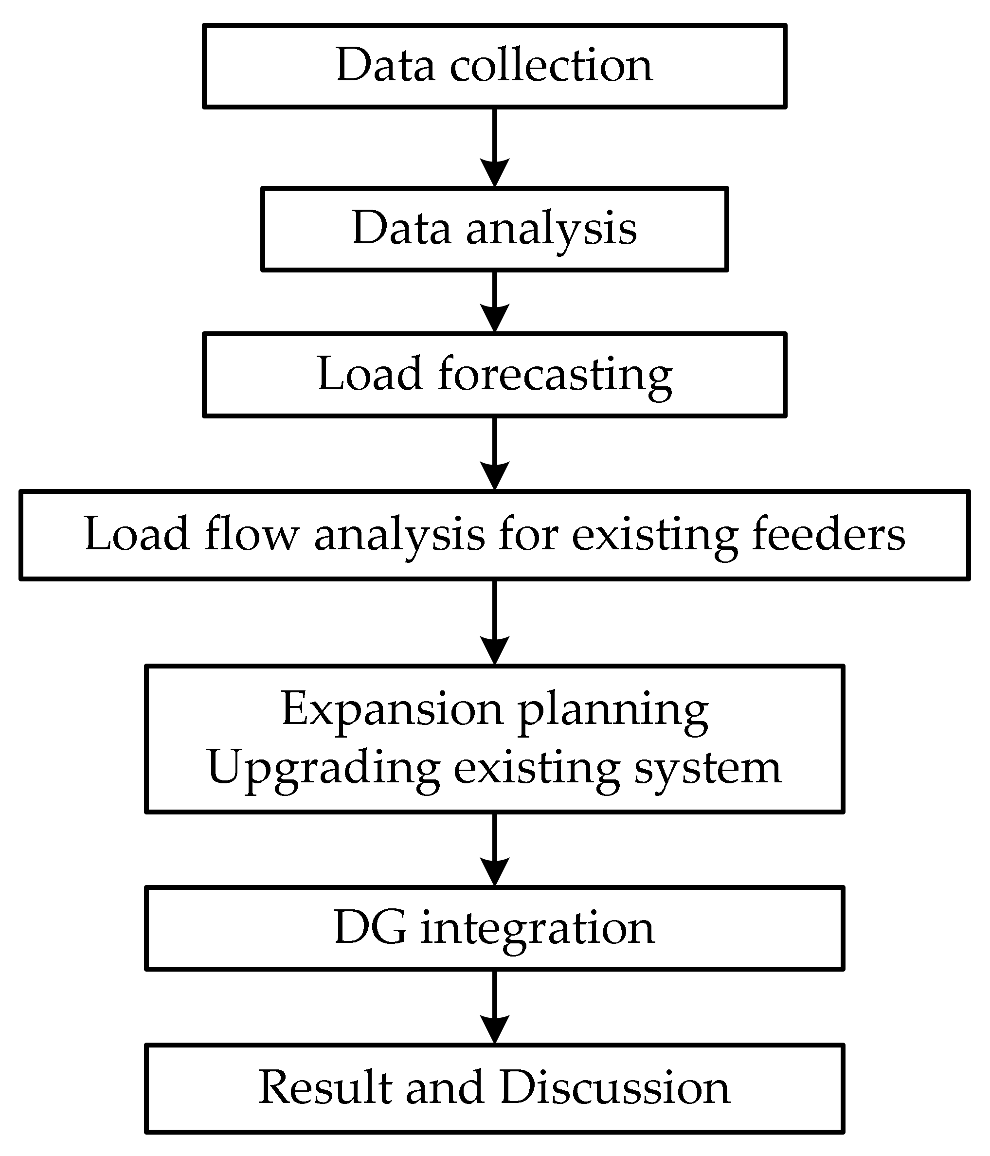
2. Methodology
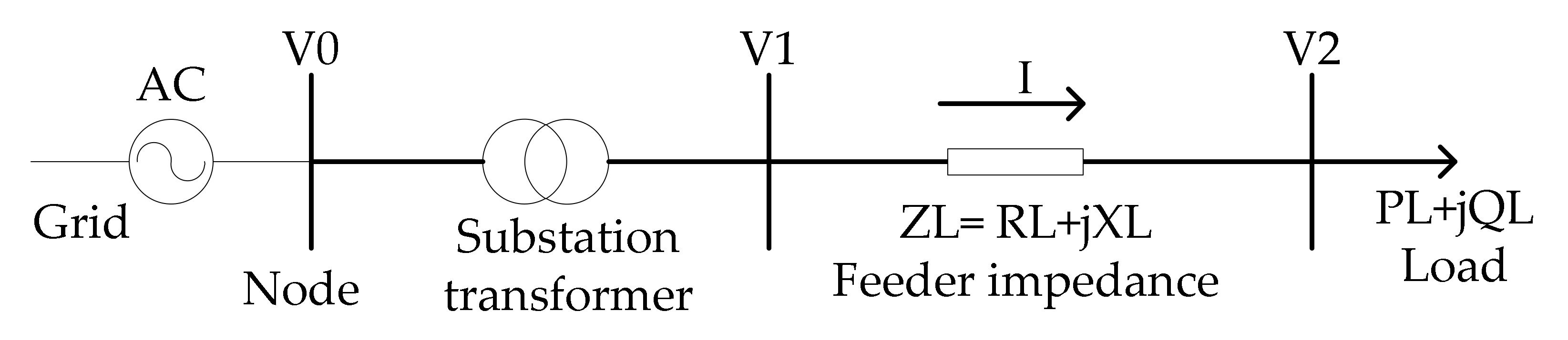
2.1. System Modeling and Load Flow Analysis
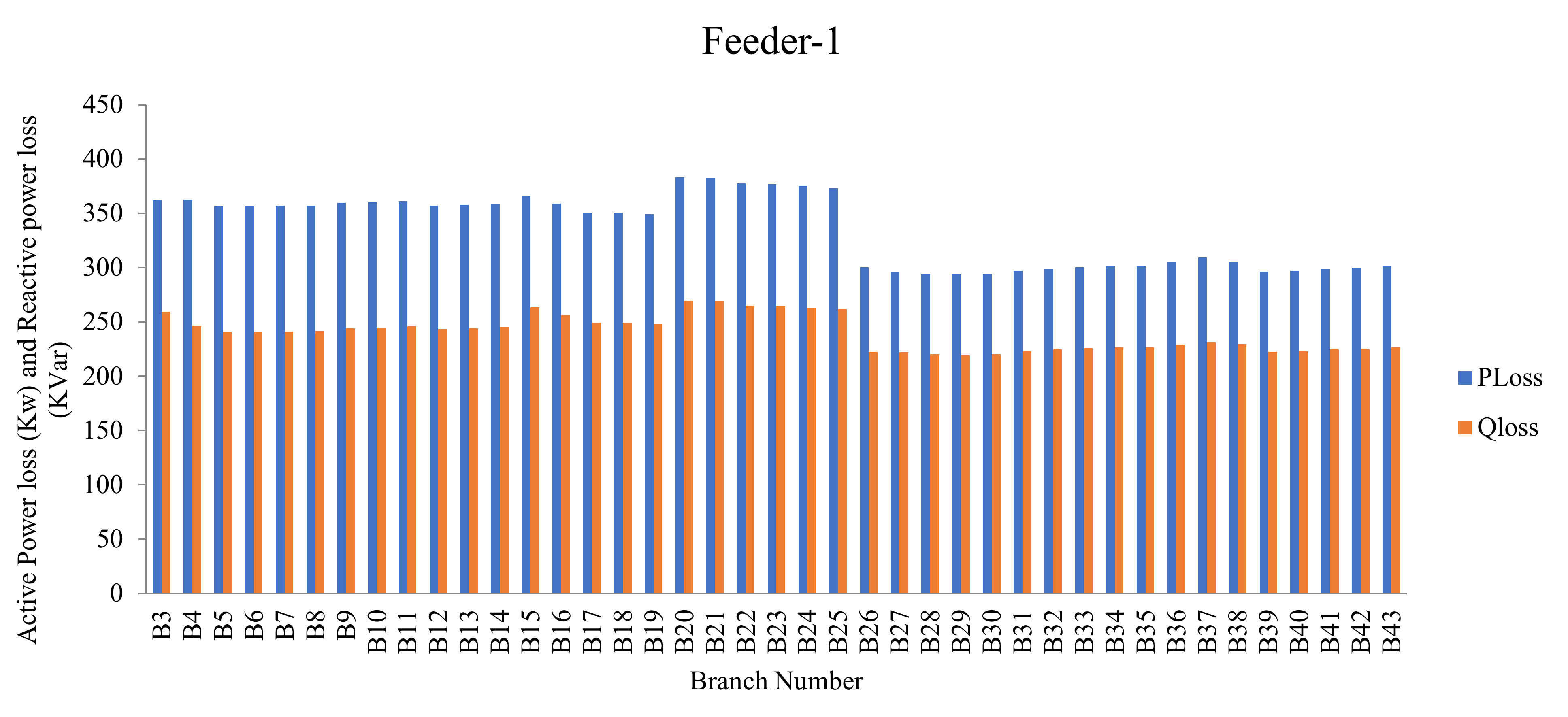
2.1.1. Power Loss Calculation
2.1.2. Voltage Drop
2.1.3. Conductor Size Selection
2.1.4. Transformer Size Selection
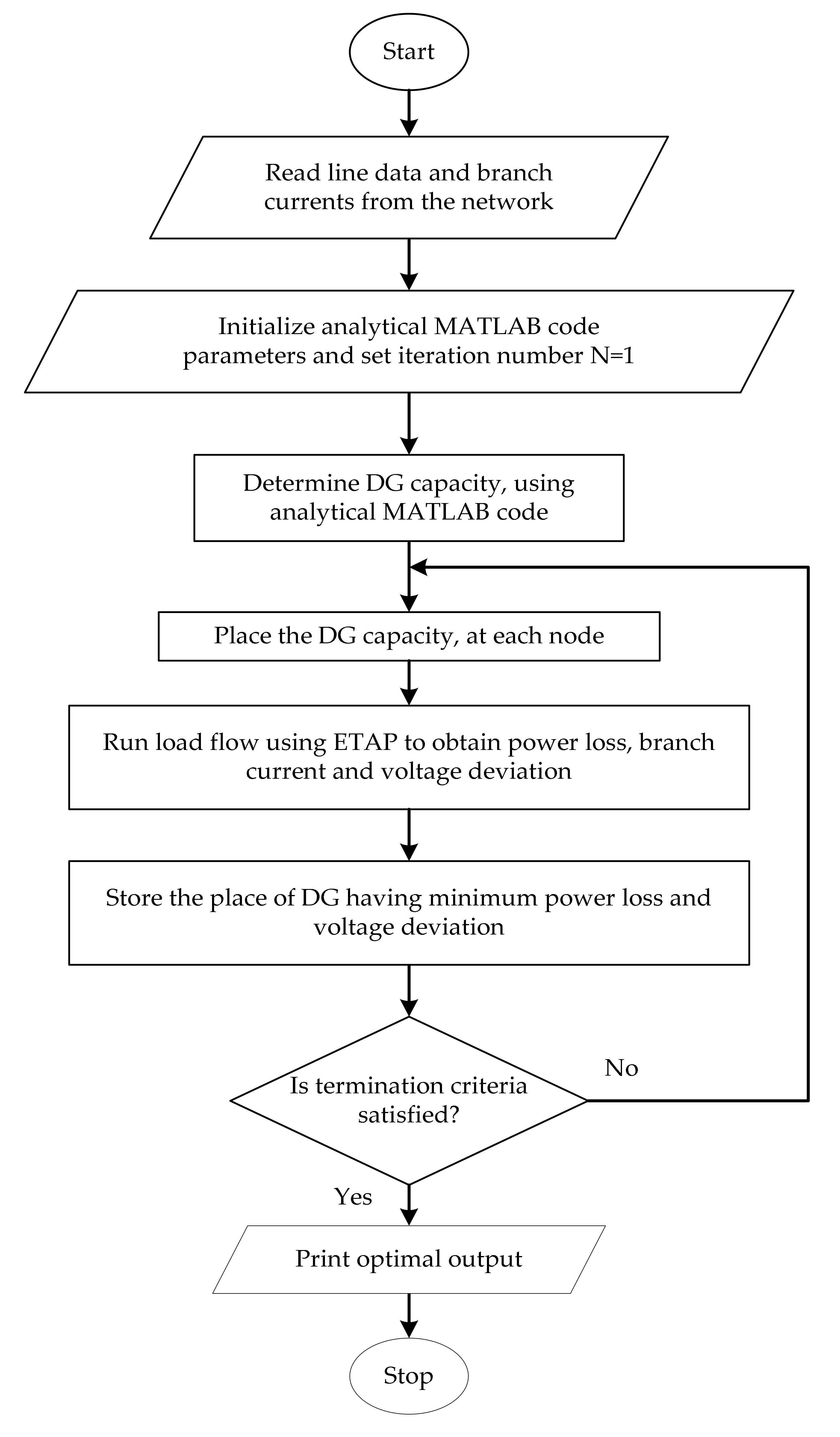
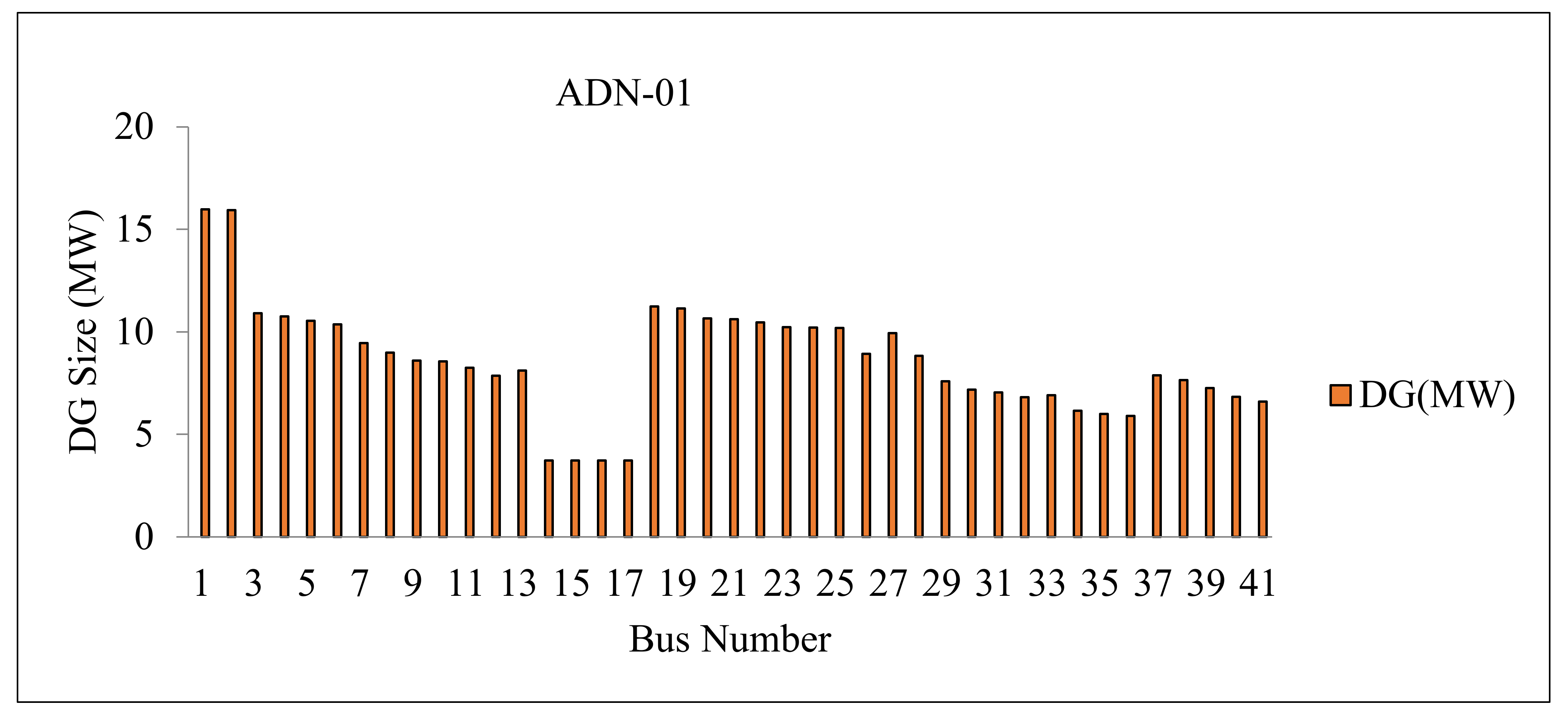
2.2. Distributed Generation Sizing and Placement
2.2.1. Problem Formulation
2.2.2. Constraints
- (a)
- Voltage limit constraints
- (b)
- The size of the ‘DG capacities’
- (c)
- The minimum power factor constraint of the DG units
- (d)
- Branch thermal limit constraint
- (e)
- Power losses constraints
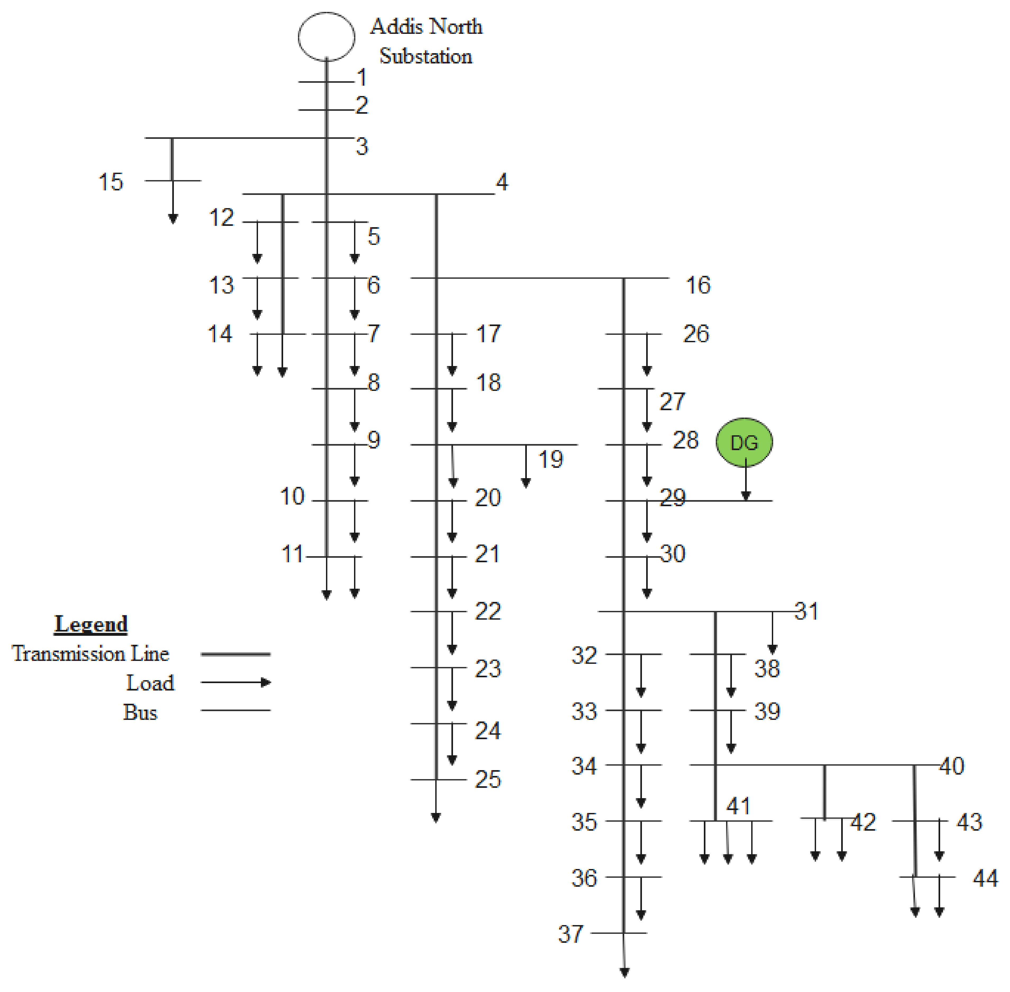
2.2.3. Identification of Location of DG
2.3. Forecasting of Peak Load
3. Result and Discussion
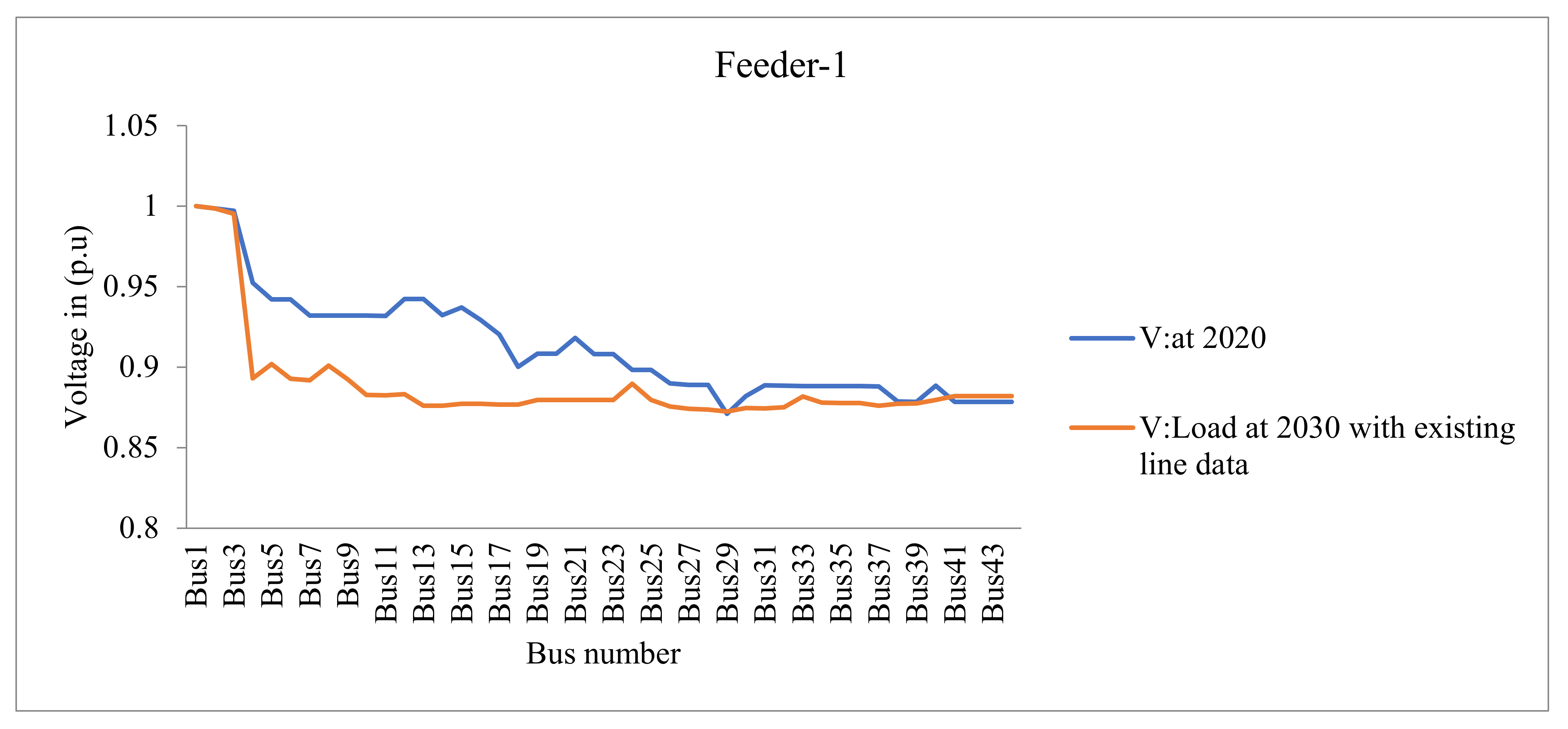
3.1. Existing Power Distribution System Assessment Up to 2030
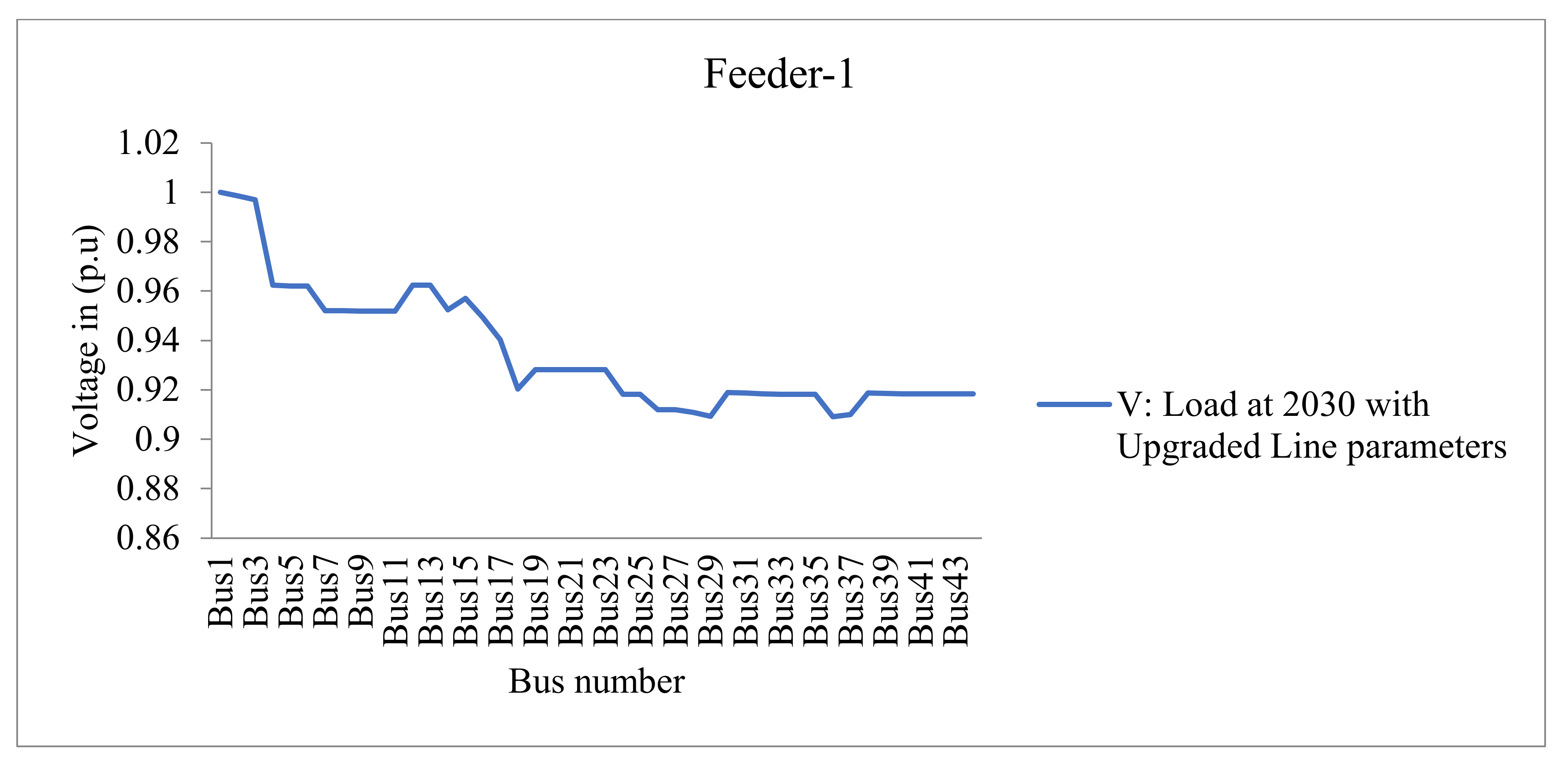
3.2. Upgraded and Added Conductor Lines and Distribution Substation (Transformer)
3.3. DG Integration on the Upgraded Existing Network
3.3.1. DG Integration on the Upgraded Existing Network
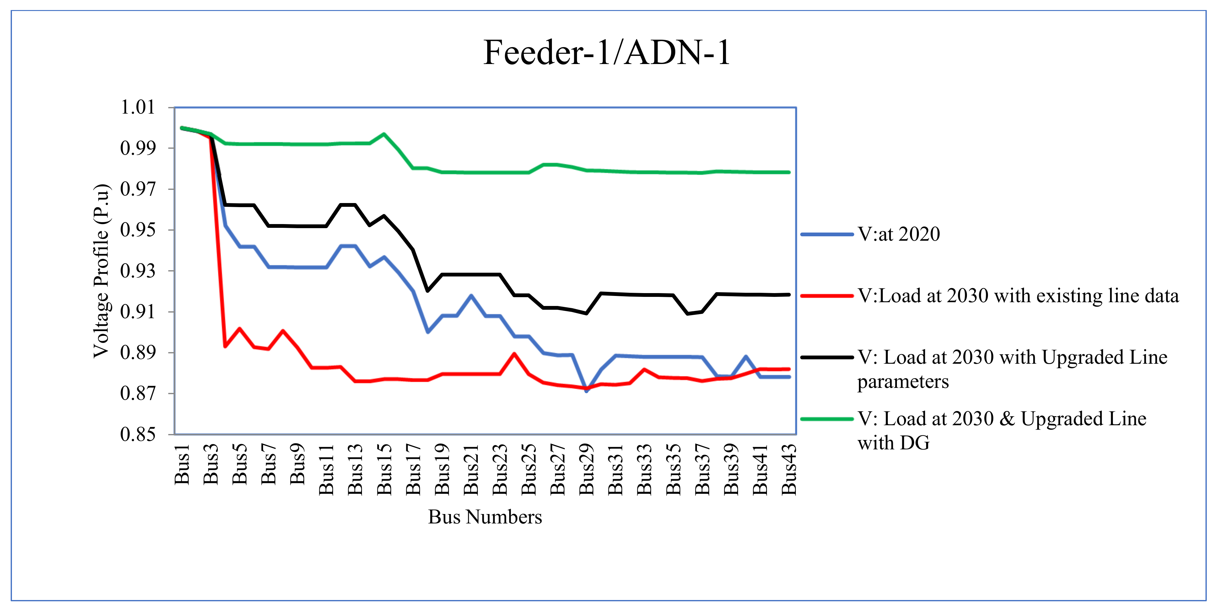
3.3.2. DG Impact on Voltage Profile
4. Conclusions
Author Contributions
Funding
Data Availability Statement
Acknowledgments
Conflicts of Interest
References
- Gómez-Expósito, A.; Conejo, A.J.; Cañizares, C. Electric Energy Systems. Analysis and Operation; CRC Press: Boca Raton, FL, USA, 2009. [Google Scholar]
- El-Khattam, W.; Hegazy, Y.G.; Salama, M.M.A. An integrated distributed generation optimization model for distribution system planning. IEEE Trans. Power Syst. 2015, 20, 1158–1165. [Google Scholar] [CrossRef]
- Farrag, M.A.; El-Metwally, M.M.; El-Bages, M.S. A new model for distribution system planning. Electr. Power Energy Syst. 2009, 21, 523–531. [Google Scholar] [CrossRef]
- Willis, H.L. Power Distribution Planning Reference Book, 2nd ed.; Marcel Dekker: New York, NY, USA, 2014; p. 1217. [Google Scholar]
- Pregelj, A.; Begovic, M.; Rohatgi, A. Recloser allocation for improved reliability of DG-enhanced distribution networks. IEEE Trans. Power Syst. 2016, 21, 1442–1449. [Google Scholar] [CrossRef]
- Gil, H.A.; Joos, G. On the Quantification of the Network Capacity Deferral Value of Distributed Generation. IEEE Trans. Power Syst. 2006, 21, 1592–1599. [Google Scholar] [CrossRef]
- Ahmadigorji, M.; Amjady, N. A multiyear DG-incorporated framework for expansion planning of distribution networks using binary chaotic shark smell optimization algorithm. Energy 2016, 102, 199–215. [Google Scholar] [CrossRef]
- Zhang, C.; Ding, Y.; Wu, Q.; Wang, Q.; Østergaard, J. Distribution Network Expansion Planning Based on Multi-objective PSO Algorithm. Energy Power Eng. 2013, 5, 975–979. [Google Scholar] [CrossRef] [Green Version]
- Nayeripour, M.; Saeed, H.; Hossein, F.-A. Optimal expansion planning of distribution system capacity with respect to distributed generations. Int. J. Renew. Energy Res. 2018, 6, 3. [Google Scholar]
- Li, R.; Wang, W.; Chen, Z.; Jiang, J.; Zhang, W. A Review of Optimal Planning Active Distribution System: Models, Methods, and Future Researches. Energies 2017, 10, 1715. [Google Scholar] [CrossRef] [Green Version]
- Minyou, H.; Yuan, C. Simulated annealing algorithm of optimal reconstruction in distribution system. Autom. Electr. Power Syst. 2009, 2. [Google Scholar]
- Najafi, S.; Shafie-Khah, M.; Hajibandeh, N.; Osório, G.J.; Catalão, J.P.S. A New DG Planning Approach to Maximize Renewable-Based DG Penetration Level and Minimize Annual Loss; Springer: Cham, Switzerland, 2017. [Google Scholar]
- Raut, U.; Mishra, S. Power distribution network reconfiguration for loss minimization using a new graph theory based genetic algorithm. In Proceedings of the 2017 IEEE Calcutta Conference (CALCON), Kolkata, India, 2–3 December 2017; pp. 1–5. [Google Scholar]
- Tolba, M.A.; Tulsky, V.N.; Diab, A.A.Z. Optimal sitting and sizing of renewable distributed generations in distribution networks using a hybrid PSOGSA optimization algorithm. In Proceedings of the 2017 IEEE International Conference on Environment and Electrical Engineering and 2017 IEEE Industrial and Commercial Power Systems Europe (EEEIC/I&CPS Europe), Milan, Italy, 6–9 June 2017; pp. 1606–1612. [Google Scholar]
- Mohan, V.J.; Albert, T.A.D. Optimal Sizing and Sitting of Distributed Generation Using Particle Swarm Optimization Guided Genetic Algorithm. In Advances in Computational Sciences and Technology; Reseaech India Publications: Delhi, India, 2017; Volume 10, pp. 709–720. [Google Scholar]
- Abdel-Mawgoud, H.; Kamel, S.; Ebeed, M.; Aly, M.M. An efficient hybrid approach for optimal allocation of DG in radial distribution networks. In Proceedings of the 2018 International Conference on Innovative Trends in Computer Engineering (ITCE), Aswan, Egypt, 19–21 February 2018; pp. 311–316. [Google Scholar]
- Vidyasagar, S.; Vijayakumar, K.; Ramanujam, R.; Sattianadan, D.; Kumar, N. Voltage profile improvement using DG in reconfigured distribution system. Int. J. Control Autom. 2019, 8, 393–410. [Google Scholar] [CrossRef]
- Nick, M.; Rachid, C.; Mario, P. Optimal planning of distributed energy storage systems in active distribution networks embedding grid reconfiguration. IEEE Trans. Power Syst. 2017, 99, 1. [Google Scholar] [CrossRef] [Green Version]
- Sarfaraz; Bansal, A.; Singh, S. Optimal allocation and sizing of distributed generation for power loss reduction. In Proceedings of the International Conference & Workshop on Electronics & Telecommunication Engineering (ICWET 2016), Mumbai, India, 26–27 February 2016. [Google Scholar]
- Haider, W.; Hassan, S.J.U.; Mehdi, A.; Hussain, A.; Adjayeng, G.O.M.; Kim, C.-H. Voltage Profile Enhancement and Loss Minimization Using Optimal Placement and Sizing of Distributed Generation in Reconfigured Network. Machines 2021, 9, 20. [Google Scholar] [CrossRef]
- Podder, A.K.; Islam, S.; Kumar, N.M.; Chand, A.A.; Rao, P.N.; Prasad, K.A.; Logeswaran, T.; Mamun, K.A. Systematic categorization of optimization strategies for virtual power plants. Energies 2020, 13, 6251. [Google Scholar] [CrossRef]
- Badar, E.; Islam, U. Comparison of conventional and modern load forecasting techniques based on artificial intelligence and expert systems. Int. J. Comput. Sci. Issues 2016, 8, 504–513. [Google Scholar]
- Singh, A.K.; Khatoon, I.S.; Muazzam, M. An overview of electricity demand forecasting techniques. Netw. Complex Syst. 2013, 3, 38–48. [Google Scholar]
- Ang, S.; Leeton, U. Optimal placement and size of distributed generation in radial distribution system using whale optimization algorithm. Suranaree J. Sci. Technol. 2019, 1, 26. [Google Scholar]
- Bashir, A.; Khan, J.; Rana, A.; Junaid, M.; Mansoor Asghar, M. ETAP software based transient, ground grid and short circuit analyses of 132 kV grid. AIP Conf. Proc. 2010, 1239, 25–30. [Google Scholar]
- Sa’ed, J.A.; Amer, M.; Bodair, A.; Baransi, A.; Favuzza, S.; Zizzo, G. A Simplified Analytical Approach for Optimal Planning of Distributed Generation in Electrical Distribution Networks. Appl. Sci. 2019, 9, 5446. [Google Scholar] [CrossRef] [Green Version]
- Patel, M.R. Wind and Solar Power Systems: Design, Analysis, and Operation; CRC Press: Boca Raton, FL, USA, 2015. [Google Scholar]
- Pandey, D.; Bhadoriya, J.S. Optimal placement & sizing of distributed generation (DG) to minimize active power loss using particle swarm optimization (PSO). Int. J. Sci. Technol. Res. 2014, 3, 246–254. [Google Scholar]
- Mahmoud, K.; Lehtonen, M. Simultaneous allocation of multi-type distributed generations and capacitors using generic analytical expressions. IEEE Access 2019, 16, 182701–182710. [Google Scholar] [CrossRef]
- Murty, V.V.; Kumar, A. Optimal DG integration and network reconfiguration in microgrid system with realistic time varying load model using hybrid optimization. IET Smart Grid. 2019, 2, 192–202. [Google Scholar] [CrossRef]
- Hosseini, S.A.; Madahi, S.S.K.; Razavi, F.; Karami, M.; Ghadimi, A.A. Optimal sizing and siting of distributed generation resources using a multiobjective algorithm. Turk. J. Electr. Eng. Comput. Sci. 2015, 21, 825–850. [Google Scholar]
- Kersting, W.H.; Fellow, L.; Green, R.K.; Member, L.S. The Application of Carson’s Equation to the Steady-State Analysis of Distribution Feeders. In Proceedings of the 2011 IEEE/PES Power Systems Conference and Exposition, Phoenix, AZ, USA, 20–23 March 2011; pp. 1–6. [Google Scholar]


| Year | Xi | Peak Load (Mw) = Y | Xi2 | XiY |
|---|---|---|---|---|
| 2015 | 1 | 7.37 | 1 | 7.37 |
| 2016 | 2 | 7.99 | 4 | 15.98 |
| 2017 | 3 | 8.73 | 9 | 26.19 |
| 2018 | 4 | 9 | 16 | 36 |
| 2019 | 5 | 8.09 | 25 | 40.45 |
| 2020 | 6 | 10.42 | 36 | 62.52 |
| 21 | 51.6 | = 91 | = 188.51 |
| Year | ADN1 | ADN2 | ADN3 | ADN4 | ADN5 | ADN1 | ADN2 | ADN3 | ADN4 | ADN5 |
|---|---|---|---|---|---|---|---|---|---|---|
| Actual | Forecasted | |||||||||
| 2015 | 7.37 | 9.74 | 7.13 | 5.79 | 8.98 | 7.52 | 9.95 | 7.25 | 5.7 | 8.69 |
| 2016 | 7.99 | 10.84 | 7.3 | 6.06 | 9.08 | 7.91 | 10.17 | 7.63 | 5.96 | 8.78 |
| 2017 | 8.73 | 9.94 | 8.11 | 5.71 | 8.33 | 8.33 | 10.39 | 8.03 | 6.23 | 8.88 |
| 2018 | 9 | 10.44 | 9.62 | 6.95 | 8.48 | 8.77 | 10.62 | 8.44 | 6.51 | 8.97 |
| 2019 | 8.09 | 11.06 | 8.63 | 6.68 | 9.15 | 9.23 | 10.86 | 8.88 | 6.8 | 9.07 |
| 2020 | 10.42 | 11.11 | 8.88 | 7.15 | 9.6 | 9.72 | 11.10 | 9.34 | 7.11 | 9.17 |
| 2021 | - | - | - | - | - | 10.23 | 11.35 | 9.83 | 7.43 | 9.27 |
| 2022 | - | - | - | - | - | 10.77 | 11.60 | 10.3 | 7.76 | 9.37 |
| 2023 | - | - | - | - | - | 11.34 | 11.85 | 10.9 | 8.11 | 9.47 |
| 2024 | - | - | - | - | - | 11.94 | 12.12 | 11.4 | 8.48 | 9.57 |
| 2025 | - | - | - | - | - | 12.57 | 12.39 | 12 | 8.86 | 9.67 |
| 2026 | - | - | - | - | - | 13.23 | 12.66 | 12.7 | 9.26 | 9.78 |
| 2027 | - | - | - | - | - | 13.93 | 12.94 | 13.3 | 9.68 | 9.88 |
| 2028 | - | - | - | - | - | 14.66 | 13.23 | 14 | 10.11 | 9.99 |
| 2029 | - | - | - | - | - | 15.44 | 13.52 | 14.7 | 10.57 | 10.1 |
| 2030 | - | - | - | - | - | 16.25 | 13.82 | 15.5 | 11.05 | 10.2 |
| Feeder Name | Demand at 2020 (MW) | Line Data | Demand | P Loss(kW) | Q Loss(kVAr) | Overloaded Lines | Overloaded Transformers |
|---|---|---|---|---|---|---|---|
| ADN-01 | 10.42 | At 2020 | At 2020 | 320.9 | 184.2 | Yes | Yes |
| At 2030 | 542.0 | 397.4 | Yes | Yes |
| Name of the Feeder | Type of Existing Conductor | Type of Upgraded Conductor | ||
|---|---|---|---|---|
| ADN-01 | Length (km) | Length (km) | ||
| AAAC-150 | 3.16 | AAAC_200 | 0.67 | |
| AAAC_400 | 0.45 | |||
| AAAC_400 | 0.74 | |||
| AAAC_120 | 0.1 | AAAC_200 | 0.1 | |
| AAAC_95 | 0.755 | AAAC_200 | 0.63 | |
| AAAC_150 | 0.126 | |||
| Year | Transformer Rating (kVA) | Total (MVA) | |||||||
|---|---|---|---|---|---|---|---|---|---|
| 25 | 50 | 100 | 200 | 315 | 400 | 500 | 630 | ||
| Existing Transformers at 2020 | 3 | 4 | 3 | 6 | 18 | 3 | 1 | 7 | 13.555 |
| Transformers at 2030 | ------ | ---- | --- | 3 | 9 | 12 | 13 | 8 | 19.775 |
| Feeder | Line Data | Demand | PLoss (kW) | QLoss (kVAr) | Overload Line | Overload Transformer |
|---|---|---|---|---|---|---|
| Feeder-1 | Upgraded | At 2030 | 372.1 | 272.5 | No | No |
Publisher’s Note: MDPI stays neutral with regard to jurisdictional claims in published maps and institutional affiliations. |
© 2022 by the authors. Licensee MDPI, Basel, Switzerland. This article is an open access article distributed under the terms and conditions of the Creative Commons Attribution (CC BY) license (https://creativecommons.org/licenses/by/4.0/).
Share and Cite
Ayalew, M.; Khan, B.; Giday, I.; Mahela, O.P.; Khosravy, M.; Gupta, N.; Senjyu, T. Integration of Renewable Based Distributed Generation for Distribution Network Expansion Planning. Energies 2022, 15, 1378. https://doi.org/10.3390/en15041378
Ayalew M, Khan B, Giday I, Mahela OP, Khosravy M, Gupta N, Senjyu T. Integration of Renewable Based Distributed Generation for Distribution Network Expansion Planning. Energies. 2022; 15(4):1378. https://doi.org/10.3390/en15041378
Chicago/Turabian StyleAyalew, Mulusew, Baseem Khan, Issaias Giday, Om Prakash Mahela, Mahdi Khosravy, Neeraj Gupta, and Tomonobu Senjyu. 2022. "Integration of Renewable Based Distributed Generation for Distribution Network Expansion Planning" Energies 15, no. 4: 1378. https://doi.org/10.3390/en15041378
APA StyleAyalew, M., Khan, B., Giday, I., Mahela, O. P., Khosravy, M., Gupta, N., & Senjyu, T. (2022). Integration of Renewable Based Distributed Generation for Distribution Network Expansion Planning. Energies, 15(4), 1378. https://doi.org/10.3390/en15041378