Article

Energy Savings in Hydraulic Hybrid Transmissions through Digital Hydraulics Technology

School of Engineering Technology, Purdue University, West Lafayette, IN 47906, USA
*
Author to whom correspondence should be addressed.
Energies 2022, 15(4), 1348; https://doi.org/10.3390/en15041348
Submission received: 6 January 2022 / Revised: 30 January 2022 / Accepted: 10 February 2022 / Published: 13 February 2022
(This article belongs to the Special Issue Application and Analysis in Fluid Power Systems)

Abstract

:
Hydraulic hybrid drivetrains, which are fluid power technologies implemented in automobiles, present a popular alternative to conventional drivetrain architectures due to their high energy savings, flexibility in power transmission, and ease of operation. Hydraulic hybrid drivetrains offer multiple environmental benefits compared to other power transmission technologies. They provide heavy-duty vehicles, e.g., commercial transportation, construction equipment, wagon handling, drilling machines, and military trucks, with the potential to achieve better fuel economy and lower carbon emissions. Despite the preponderance of hydraulic hybrid transmissions, state-of-the-art hydraulic hybrid drivetrains have relatively low efficiencies, around 64% to 81%. This low efficiency is due to the utilization of conventional variable displacement pumps and motors that experience high power losses throughout the drive cycle and thus fail to maintain high operating efficiency at lower volumetric displacements. This work proposes and validates a new methodology to improve the overall efficiency of hydraulic hybrid drivetrains by replacing conventional pump/motor units with their digital counterparts. Compared to conventional pump/motors, the digital pump/motor can achieve higher overall efficiencies at a wide range of operating conditions. A proof-of-concept digital pump/motor prototype was built and tested. The experimental data were integrated into a multi-domain physics-based simulation model of a series hydraulic hybrid transmission. The proposed methodology permits enhancing the overall efficiency of a series hydraulic hybrid transmission and thus allows for energy savings. Simulating the system at moderate load-speed conditions allowed achieving a total efficiency of around 89%. Compared to the average efficiency of the series hydraulic hybrid drivetrains, our simulation results reveal that the utilization of the state-of-the-art digital pump enables improving the total efficiency of the series hydraulic hybrid drivetrain by up to 25%.

1. Introduction

Fluid power has a vast area of engineering technology, where it uses pressurized fluids to generate, monitor and control, and transmit power [1]. Hydraulic oil is typically used due to its low freezing point, high boiling point, relatively large bulk modulus, and self-lubrication characteristics [2]. Fluid power has a well-defined research area and scholarly activities, which serves widespread industries like agriculture, construction, transportation, aerospace, marine, manufacturing, and many other industries that require high power to weight ratios [3]. In addition to its capability of achieving high power densities, fluid power is characterized by its flexibility in transmission, ease of operation, relatively low cost, controllability, and manageability [4]. These advantages make fluid power technology convenient for performing crucial operations that require high power density and reliability, like heavy-duty applications, e.g., construction vehicles, material handling equipment, and military operations [5].
The fluid power sector is a Workhorse of the United States economy [6]. According to the National Fluid Power Association (NFPA), thousands of companies in the United States utilize hydraulic power systems. Such companies are renowned as the top industrial U.S. firms, involving more than 845,000 employees for an annual payroll of more than $60 billion [7]. The fluid power sector has multiple application areas. Four main application areas comprise mobile hydraulics, industrial hydraulics, pneumatics, and aerospace [8].
Hydraulic hybrid technology, a subset of mobile hydraulics, is considered one of the pioneer frameworks in automobiles. It is a desirable research topic widely examined by scholars to improve the overall efficiency of power transmission between a prime mover and the wheels. This technology allows for high fuel efficiency and offers energy savings and multiple environmental benefits, becoming a popular alternative to conventional drivetrain configurations [9]. Hydraulic hybrid drivetrains offer multiple benefits over the conventional manual/automatic transmissions and the continuously variable transmissions (CVTs). Unlike conventional drivetrains and CVTs, hydraulic hybrid drivetrains comprise two power sources: the prime mover (an internal combustion engine or electric motor) and a positive variable displacement pump/motor installed with a high-pressure storage device (accumulator) [10]. The variable displacement pump allows achieving variable speeds by regulating the flow rate, which prevents the gearshift discontinuities in conventional drivetrains (manual/automatic) during speed regulation. CVTs do not experience excessive gearshift discontinuities during speed regulation. However, CVTs have limited belts, also known as chain strengths, which cause torsional moments, generating excessive frictional forces and torsional moments [11]. Besides this advantage, utilizing a hydraulic accumulator in hydraulic hybrid drivetrains allows for better power management [12]. The accumulator enables storing and discharging energy and thus achieving higher overall efficiencies and energy savings while attaining lower carbon emissions and better fuel economy [13].
In addition to its preponderance over manual/automatic drivetrains and CVTs, the hydraulic hybrid drivetrains have many advantages over electric hybrid transmission [14,15]. Although electric hybrid systems also utilize a transmission source and an energy storage source (batteries), the batteries in electric systems can only charge and discharge around 20% of energy available during braking [16]. However, the accumulators employed in the hydraulic hybrid transmissions can store and deliver up to 80% of the braking energy [17], depending on the duty cycle. This operation is desirable during vehicle acceleration/deceleration to improve fuel economy and reduce emissions [18,19]. It permits transmitting a large amount of energy rapidly, thus attaining higher power densities and power to weight ratios [20].
These advantages make the hydraulic hybrid technology more convenient for heavy-duty operations [21], like heavy equipment manufacturing, road appliances, heavy load material handling equipment, and many other types of equipment that require high power densities and energy capture. For instance, commercial vehicles, such as heavy load vehicles undergoing high dynamic-drive-cycle operations, have started to rely on this transmission technology. They carry bulky loads while experiencing continual stops, requiring more braking and high energy capture [15]. Besides heavy-duty vehicles, some utility vehicles designed to carry light weights also rely on hydraulic hybrid technology. For example, a sport utility vehicle was developed in a research laboratory to demonstrate the concept of a hydraulic hybrid transmission in a passenger vehicle. The vehicle was designed to operate the system in four different modes: hydrostatic driving mode, hybrid driving mode, a combination of hydrostatic and hybrid driving modes, and braking mode [22].
This paper is organized as follows: Section 2 exhibits a review of the currently existing hydraulic hybrid transmissions. It introduces the different available hydraulic hybrid drivetrain configurations: series, parallel, and series-parallel, and it discusses the overall operation of each. Section 3 presents a series of notable applications on hydraulic hybrid drivetrains. Section 4 formulates the problem statement of this work, elucidating the inadequacies of the currently existing hydraulic hybrid drivetrains. Moreover, it highlights and introduces the adopted methodology to overcome such inadequacies. Section 5 gives an overview of digital hydraulics technology in fluid power and presents the design of the state-of-the-art digital pump, its basic operation, digital motoring/pumping data, and the capability to achieve high efficiencies at different pump displacements. Section 6 demonstrates the hydraulic hybrid transmission efficiency improvement after integrating digital hydraulics by simulating a physical series hydraulic hybrid architecture using the intended digital motoring/pumping data. It presents the adopted circuit schematic, the comprehensive simulation model, and the resulting outcomes. Section 7 concludes with a brief discussion of the main ideas learned from the work.

2. Existing Hydraulic Hybrid Transmission Configurations

Three main architectures of hydraulic hybrid transmission drivetrains are currently available: the parallel configuration, series configuration, and the series-parallel configuration. These hydraulic hybrid transmission configurations employ a variable displacement pump/motor, a high-pressure reservoir for energy storage (typically a nitrogen accumulator), and a low-pressure reservoir (fluid tank) [23]. The variable displacement pump/motor acts as a motor when converting the hydraulic energy into mechanical energy to drive the vehicle. It acts as a pump when converting the mechanical energy into hydraulic energy stored in the accumulator to be delivered when needed.
The following sections exhibit a brief review of existing relevant hydraulic hybrid drivetrains (parallel, series, and series-parallel) and discuss their overall operation.

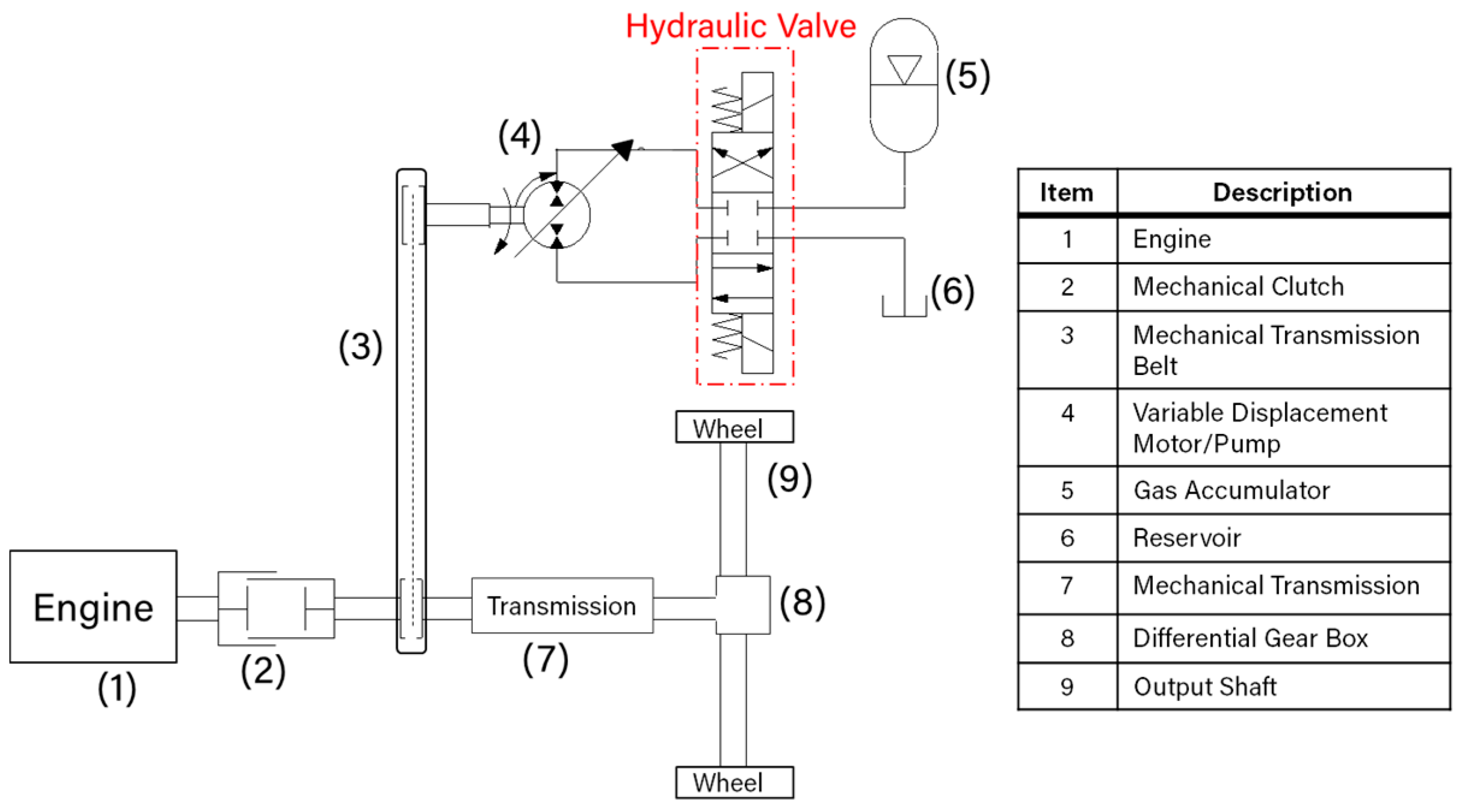
2.1. Parallel Hydraulic Hybrid Configuration

A parallel hydraulic hybrid has a simple architecture, design, and implementation compared to other configurations [24]. It involves two sub-systems: a conventional mechanical transmission directly connected to the output shaft via a differential gearbox and a hydraulic transmission [25]. The sub-systems are coupled in parallel using a mechanical power transmitter like a gearbox, a chain, or a belt. Figure 1 shows a parallel hydraulic hybrid configuration utilizing a belt mechanical power transmitter. As shown in Figure 1, the drivetrain consists of mechanical transmission (7), a clutch (2), and the prime mover (1), typically an internal combustion engine. The mechanical transmission (7) is directly connected to the engine (1) via the clutch component (2) and to the differential gearbox (8) on the drive shaft (9) to provide the needed power to each wheel. The hydraulic drivetrain comprises a variable displacement pump/motor (4), an accumulator (5), a fluid tank (6), and other hydraulic components, e.g., valves and fittings. The hydraulic pump/motor (4) is connected in parallel to the mechanical transmission (7) via the belt linkage (3). The clutch (2) allows engaging and disengaging the engine shaft from the rest of the system based on the accumulator’s stored energy, thus controlling the engine on/off signal [26]. For instance, decoupling the engine from the system occurs when enough energy is in the accumulator to boost the wheels during acceleration. However, engaging the engine shaft to the transmission shaft is required to drive the wheels at low accumulator storage levels.
After introducing the basic concept beyond the parallel hybrid configuration, now, we briefly discuss its overall operation. The transmission duty cycle constitutes three main stages: acceleration, cruising, and braking. During acceleration, the accumulator acts as a hydraulic launch assist. It discharges its pressurized fluid to drive the hydraulic pump/motor (4) (operating as an energy source) and thus transforms the high-pressure energy into mechanical energy at the motor’s shaft. The mechanical belt (3) transmits the generated mechanical power to the drive shaft (9), thus boosting the motion at the wheels. At the start of the cruising phase, the accumulator’s pressure decreases below its pre-charged pressure, forcing the clutch to engage the engine shaft with the rest of the system to power the drive shaft (9) and drive the wheels. During the last stage, i.e., braking, the clutch (2) disengages the engine shaft from the drive shaft (9), the vehicle slows down. The rotary motion at the wheels is transmitted via the belt (3) to drive the hydraulic pump/motor (4) that will start acting as a pump to charge the accumulator. This cycle repeats every braking operation.

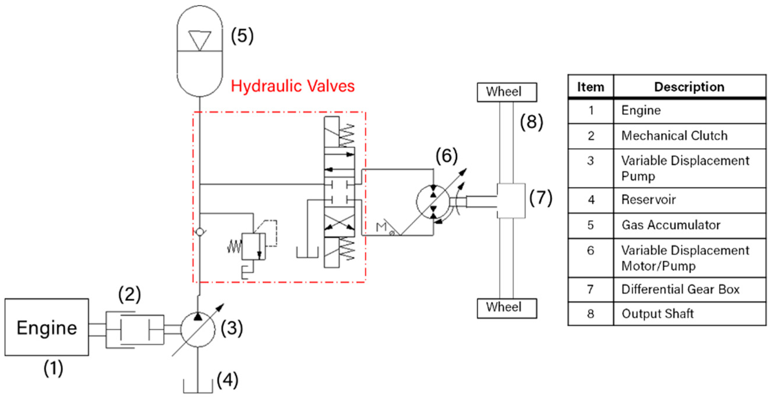
2.2. Series Hydraulic Hybrid Configuration

Unlike the parallel hydraulic hybrid configuration, the series hydraulic hybrid configuration does not utilize a mechanical transmission. Instead, it employs a variable displacement pump directly connected to the prime mover via a clutch [27]. As shown in Figure 2, in the series configuration, the mechanical transmission is replaced with a hydraulic variable displacement pump (3) connected in series to the hydraulic drivetrain consisting of a variable displacement pump/motor (6), accumulator (5), fluid tank (4), and other hydraulic components.
Similar to the parallel architecture, the operation comprises three main phases: acceleration, cruising, and braking. During the acceleration phase, the clutch (2) disengages the engine shaft from the pump shaft, and the pressurized hydraulic fluid stored in the accumulator (5) is delivered into the hydraulic pump/motor (6), allowing it to act as a motor. This operation converts the hydraulic energy in the accumulator into mechanical energy at the output shaft (8). After acceleration, cruising starts, and the fluid inside the accumulator drops to its minimum level. Its pressure decreases below the nitrogen’s pre-charge pressure, forcing the engine (1) to operate and the clutch (2) to engage. Accordingly, the engine’s energy is transmitted to the hydraulic pump (3), allowing the pump to deliver the fluid from the low-pressure reservoir (4) to the hydraulic pump/motor (6) to drive the wheels. The excess high-pressure fluid produced by the hydraulic pump is stored in the accumulator to be delivered when needed. During braking, the engine shuts down, the clutch disengages, and the hydraulic pump/motor (6) starts acting as a pump to push the fluid from the low-pressure reservoir into the accumulator. Thus, the kinetic energy from the wheels is converted into hydraulic energy stored in the accumulator. This stored energy will be used to accelerate the vehicle when needed.

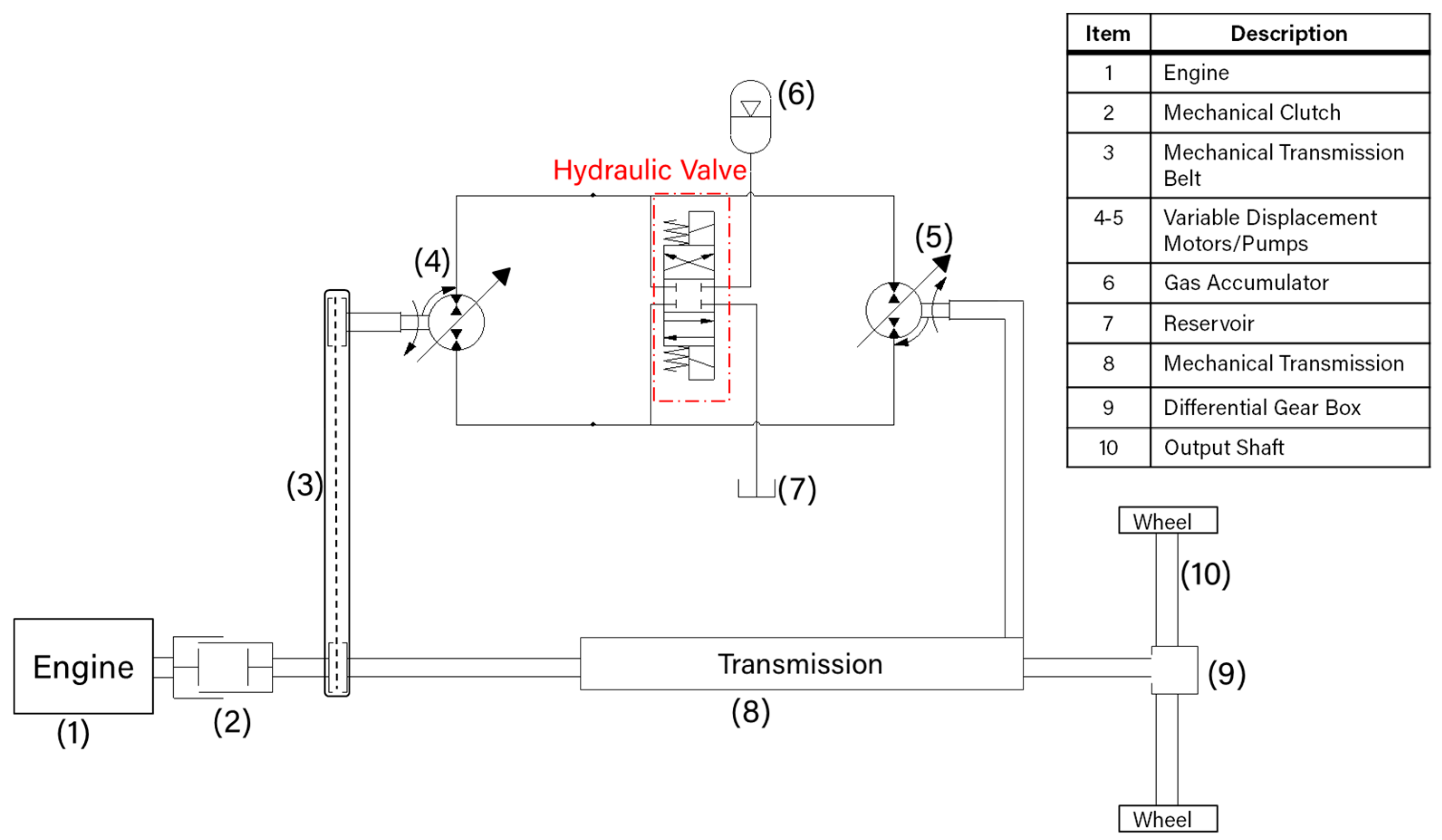
2.3. Series-Parallel Hydraulic Hybrid Configuration

The series-parallel hydraulic hybrid system, also known as power-split, comprises the series and the parallel hydraulic hybrid layouts [28]. It integrates the two hydraulic hybrid configurations in one design [29]. Like the parallel configuration, the power-split architecture, presented in Figure 3, utilizes two sub-systems coupled via a mechanical transmitter, for example, a belt (3): a conventional mechanical drivetrain and a hydraulic drivetrain. The mechanical drivetrain employs a mechanical transmission (8) directly connected to the output shaft (10) via a differential gearbox (9) and the engine (1) via a mechanical clutch (2). The hydraulic drivetrain comprises two variable displacement pump/motors (4 & 5), accumulator (6), low-pressure reservoir (7), and other hydraulic components. Similar to the series architecture, the hydraulic transmission is directly connected to the output shaft (10).
This configuration enables operating the system in two different modes: pure hydraulic mode and hybrid mode. The pure hydraulic mode offers a simultaneous operation of the variable displacement pump/motors (4 & 5). However, the hybrid mode allows a seamless operation of the mechanical transmission (8) and the hydraulic drivetrain [30]. The seamless integration between the mechanical drivetrain and the hydraulic system allows transmitting the power from the engine to the wheels while maintaining optimal engine operation. This mechanism permits achieving high mechanical transmission performance in addition to the high-efficiency energy storage and regeneration, and thus operating the system at higher overall efficiency and lower fuel consumption. However, the design comes at the expense of increased system complexity, weight, and cost.

3. Summary of Notable Mobile Applications Using Hydraulic Hybrid Drivetrains

This section briefly reviews notable applications and proposed models for hydraulic hybrid drivetrains.
A comprehensive work presented by Stecki et al. [31] presented a review of the most notable computer simulation models of hydraulic hybrids available in the literature before 2005 and summarized the resulting simulation outcomes. The comprehensive report addresses the design, implementation, and simulation of more than eight prototype vehicles using CVT transmissions combined with hydrostatic regeneration. Most of the vehicles studied were on-road vehicles. The authors mentioned ADVISOR (National Renewable Energy Laboratory, Golden, CO, USA), the Advanced Vehicle Simulator developed by the National Renewable Energy Laboratory based in the US Department of Energy’s (DOE’s), as a simulation tool for developing hybrid drivetrain models. One of the vehicles discussed focused on a tactical vehicle, developed in MATLAB/Simulink which is created by MathWorks (an American privately held corporation based in California) and implemented in ADVISOR [32]. In this work, a Permo-Drive regenerative energy management system for an army tactical vehicle was modeled and simulated on MATLAB/Simulink. The model was then incorporated into the vehicle simulator (ADVISOR), a simulation tool for developing hybrid drivetrain models. The authors concluded their review by stating that extra fuel trails are required for examining the accuracy of the adopted fuel map and thus providing further validation of the model. Thy concluded that the accumulators might present a safety issue and recommended that their implementation require further accumulator technologies.
Besides the work of Stecki et al., the work of Stelson et al. [10] presents a simulation study of various hydraulic hybrid drivetrains comparing the three hydraulic hybrid configurations (series, parallel, and power-split). The prime mover is emulated as a combustion engine throughout their simulation studies. A dynamic programming approach is adopted, in which the fuel consumption was used as the optimization variable. The developed models reveal that the three configurations of the presented on-road vehicles (series, parallel, and power-split) improve fuel consumption for the two cycles: urban drive cycle and highway drive cycle. For the urban drive cycle, the three hydraulic hybrid configurations (series, parallel, and power-split) show an improvement of 14.7%, 53.2%, and 10.0%, respectively.
Regarding the highway drive cycle, the series, parallel, and power-split architectures were enhanced by 8.9%, 11.9%, and 8.5%, respectively. Furthermore, throughout the simulation, the employed pump/motors were oversized. This forced the units to operate at partial displacements and thus led to a low overall hydraulic efficiency.
In 2004, Wu et al. [33] utilized the dynamic programming optimization methodology to optimize the accumulator’s charging/discharging process for a Class VI parallel hydraulic hybrid delivery truck. The researchers used a 99.9 L accumulator operating at a maximum pressure of 36 MPa throughout this work. The proposed control algorithm involves two optimization parameters: the fuel consumption variable as the primary control parameter and the state of charge of the accumulator (SOC) as the secondary optimization parameter. The researchers estimated the fuel economy between 28% and 47%, depending on the efficiency of the hydraulic components. In 2009, Van Batavia [34] proposed a new control approach to monitor and regulate the hydraulic launch assist operation. The adopted strategy relies on operating the engine at its peak Torque-RPM performance. An approximate range of operation comprised between 1000 RPM to 5500 RPM and 125 N.m to 200 N.m for a Diesel engine rated for 110 kW capacity. The work claims that the proposed control strategy improved the fuel economy by 50% and reduced emissions by 40%. The proposed configuration used a variable displacement bent axis pump and a separate variable displacement bent axis motor. The bent axis units are known to have high efficiencies at 100% displacements of up to 98% [35], yet this efficiency is only achievable at high displacements and is substantially lower at low displacements.
Buchwald et al. [36] introduced a Hydraulic—Internal combustion hybrid concept and four topologies for a passenger bus in Denmark. Besides the latter work, in 2008, Eaton Hydraulics [37] presented its hydraulic launch assist system for parallel drivetrain configurations. The objective was to improve power savings by supplementing engine power while launching the vehicle from a stopped position. The system was conceived for vehicles operating with heavy stop-and-go cycles, like refuse trucks, delivery vehicles, and buses. This system, developed in collaboration with the U.S. Environmental Protection Agency, depended on using a state-of-the-art pump/motor unit specifically designed for a parallel drivetrain configuration using an axial piston design.
Tollefson et al. [38] examined a new configuration of internal combustion engine/hydro-pneumatic accumulator energy storage for automobiles. The proposed architecture requires one single hydrostatic pump-motor (P/M) unit. Computer-based simulations were conducted over a wide range of parameter variations using a suitable control strategy. The simulation results revealed that the novel concept allowed significant fuel savings. The proposed hydraulic accumulator passenger car could achieve up to 65 mpg during city driving conditions, unlike the present automobiles that can attain only 25–30 mpg under similar conditions.
Similarly, Kepner [39] presents a Hydraulic Power Assist (HPA) demonstration on a full-size sport utility vehicle. It exhibits a description of the vehicle, the resulting fuel economy data, and performance and noise outcomes. The vehicle is constructed as a collaboration between Ford Motor Company, United States Environmental Protection Agency (EPA), and Advanced Technology Division, in the context of a Cooperative Research and Development Agreement (CRAD). It utilizes a valve block provided by Ifield Technologies, a pump/motor connected in parallel to the driveshaft with the conventional powertrain, and carbon fiber accumulators acting as HPA. Results show that the utilization of the HPA improved the Environmental Protection Agency (EPA) and the Heavier Acceleration city cycles by 23.6% and 35.5%, respectively. Bozic [40] presented a hybrid configuration comprising a combustion engine as the prime mover, hydrostatic transmission, and a coexisting vehicle electric generation. According to the literature consulted, it is evident that the implementation of hybrid powertrains significantly contributes to energy savings, in some cases, as high as 50% [33,34]. Yet, the system’s efficiency may be compromised by the efficiency of the heart of the hybrid transmission; that is, the pump, the motor, or the pump/motor units. These units can operate at an efficiency as high as 98%, provided the units are operating at 100% displacement, but this may be the case of only a fixed segment of a duty cycle and may not be true at all operating conditions.

4. Inadequacies of the Existing Hydraulic Hybrid Drivetrains

Despite the prominence of fluid power transmission, the existing state-of-the-art fluid power drivetrains are ineffective [3]. A study published by the United States Department of Energy shows that, among all industries, fluid power drives have low efficiencies between 9% and 60%, depending on the application, with an average efficiency not exceeding 22% [8]. The insufficiency in the fluid power transmissions’ efficiencies is notably associated with the performance of the employed hydraulic units. The variable displacement pump/motor is an essential hydraulic unit employed in all hydraulic applications; it is the heart of fluid power systems [41]. Its efficiency significantly affects the performance and overall efficiency of fluid power transmission [42,43].
The conventional variable displacement pump/motors, i.e., existing state-of-the-art hydraulic pumps, are efficient only when operating at full displacements, whereas at partial displacements, their performance decreases until operating at low efficiencies down to 30% [42,44,45]. The insufficiency of the conventional pumps at partial or low displacements affects the system’s overall efficiency due to the high pressure that may remain in the displacement chamber, in addition to leakage and other mechanical losses [46]. Given the limited efficiency of the conventional variable displacement pump/motors, the overall efficiency of the hydraulic hybrid drivetrains is relatively low, around 64–81% [47]. This critical problem has motivated many researchers in multiple fluid power applications to propose, design, and implement new techniques and methodologies to improve the performance of hydraulic hybrid transmissions by enhancing the maximum efficiency of variable displacement vane and piston pumps [48,49,50,51,52,53,54,55]. For instance, the work in [49] addresses the pre-defined problem by proposing a dynamic seven-stage model that predicts the thickness of the fluid film between the valve plate and cylinder block in axial piston pumps to get accurate information on lubrication. In [51], relying on a coating methodology, the authors improved the overall efficiency map of axial piston pumps by minimizing the friction losses by applying nanocoatings to the pump’s slippers. Besides these works, the work in [54] provides research results for a previously executed research study. The resulting outcomes can be used to enhance the efficiency of many technological systems in power engineering and transport involving hydraulic pumps and motors. Similarly, the work in [55] focuses on improving the numerical algorithm used for solving the optimal control problem for the three-dimensional heat equation, which can improve many technological systems like hydraulic units.
All the proposed techniques in the pre-listed works still result in low overall efficiencies when operating at partial volumetric displacements. There is no noticeable improvement in the pumps’ lowest efficiency at low volumetric displacements [56]. Accordingly, the work presented in [42] proposed integrating digital technologies into fluid power systems through designing digital variable displacement pump/motors that allow maintaining high efficiencies over a wide range of displacements.
Building on the results from [41,42,57,58], this work aims at enhancing the performance and efficiency of a hydraulic hybrid transmission by simulating the implementation of an experimentally-validated digital pump/motor into a hydraulic hybrid transmission. As will be proved through a physical-based simulation, unlike the ordinary variable displacement pump/motors, the adopted digital pump/motors pursue to overcome the efficiency limitation in hydraulic hybrid drivetrains by increasing the maximum overall efficiency of the transmission.

5. Digital Hydraulics

Digital Hydraulics is a pioneering sub-field of fluid power, which relies on advanced on/off control technologies to enhance hydraulic systems’ performance, reinforce advancements in fluid power applications, and minimize energy consumption [59]. This technology can replace conventional fluid power components, such as directional control valves, with multiple switching on/off valves in a parallel configuration to improve efficiency [41]. Such valves’ configurations promote a superior design in this application because they use a poppet-style actuation that does not allow leakage across the valve, commonly seen in spool valves. In turn, this configuration reduces the system’s losses, enables more control, increases the performance and efficiency, and reduces the cost of maintaining components [60,61,62]. This technology has also been utilized in various other configurations to improve the efficiency of conventional systems, including replacing traditional check valves on fixed displacement pumps. It also enables the opportunity to limit and divert flow in conventional fixed displacement pumps allowing variable displacements [44].
Some conventional piston pump/motors, e.g., reciprocating piston pumps, utilize mechanical check valves on the inlet and outlet ports of the pump to separate the system's high- and low-pressure sides. During pumping, this configuration allows fluid to enter through the low-pressure check valve when the pump is on its intake stroke. When the pump exhausts its cylinder, pressure closes the intake check valve and opens the exhaust check valve, displacing fluid to the high-pressure side of the system. This configuration limits the pump to fixed displacements since the pressure differential in the chamber is the only method of controlling the actuation of the intake and exhaust valves. Thus, the work in [42] proposes an electrically actuated digital inline 3-piston pump that replaces the conventional valves with digital switching on/off valves. The proposed digital pump/motor is a 28cc/rev unit comprising three displacement chambers, each with two high-speed switching on/off valves. Figure 4 shows the pump/motor’s configuration for a single displacement chamber. The figure shows that Valve 1 controls the flow at the low-pressure side, and Valve 2 controls the flow at the high-pressure side. The proposed configuration allows opening or closing the valves at any time throughout the pumping/motoring cycle. This configuration adds a degree of controllability and flexibility to the system, enabling various digital pumping/motoring techniques, referred to as flow diverting and limiting operating strategies [44,63].
Besides the electrically actuated digital pump, our team designed and imple-mented a mechanically actuated digital pump, which can also achieve high efficiencies over a wide range of displacements. The following sub-sections exhibit an overview of the internal mechanical structure of the mechanically actuated digital pump, intro-duce the electrically actuated pump’s most efficient operating strategy, and present the experimental testing and validation on the electrically actuated pump.

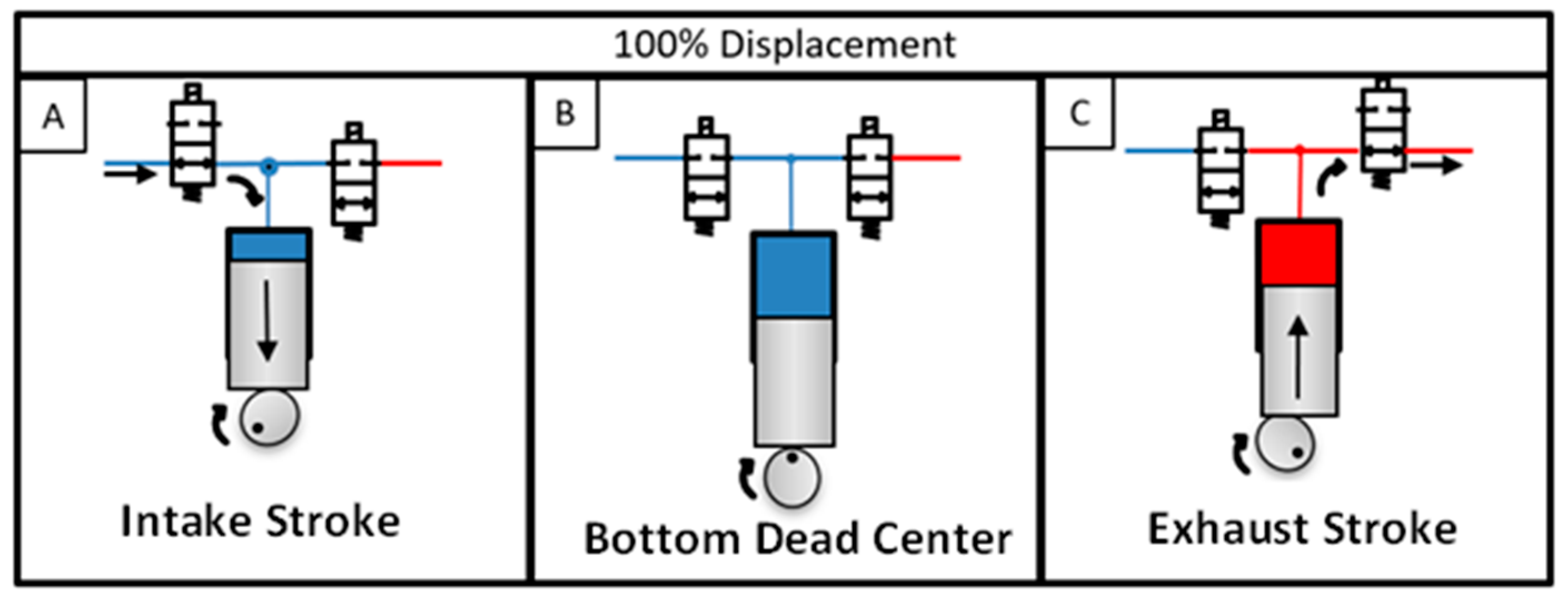
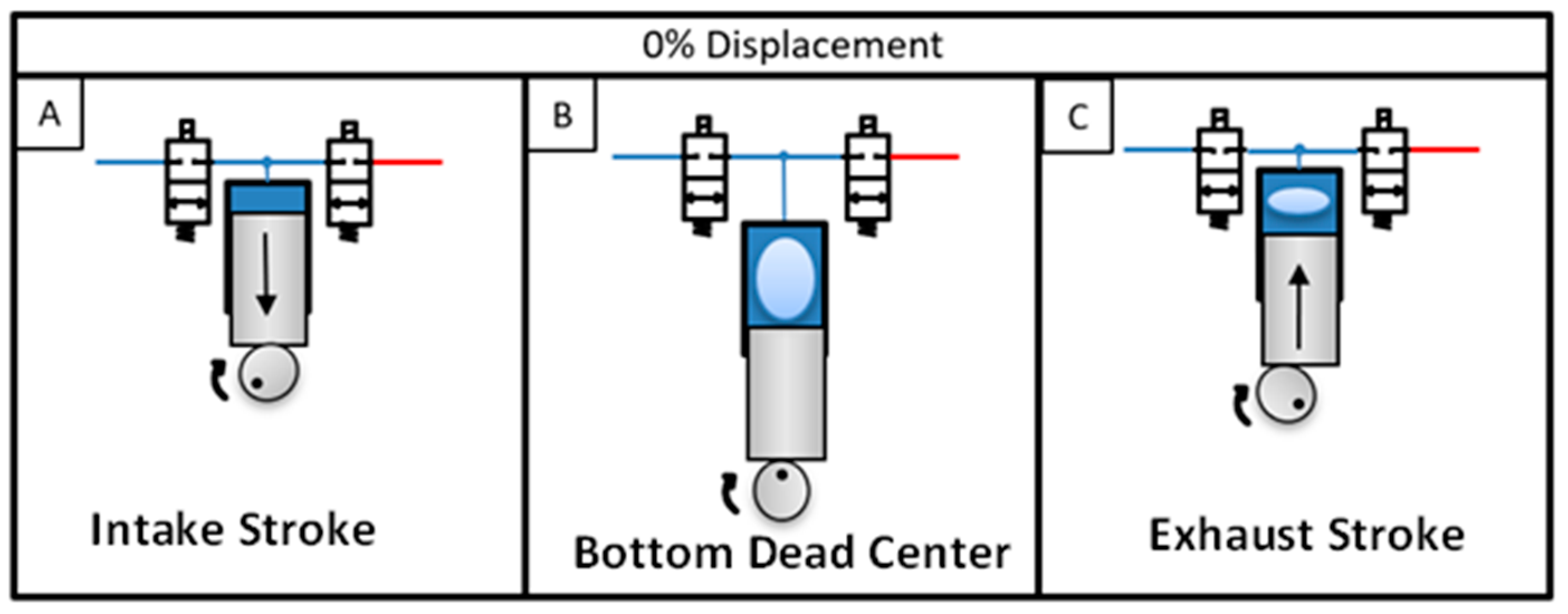
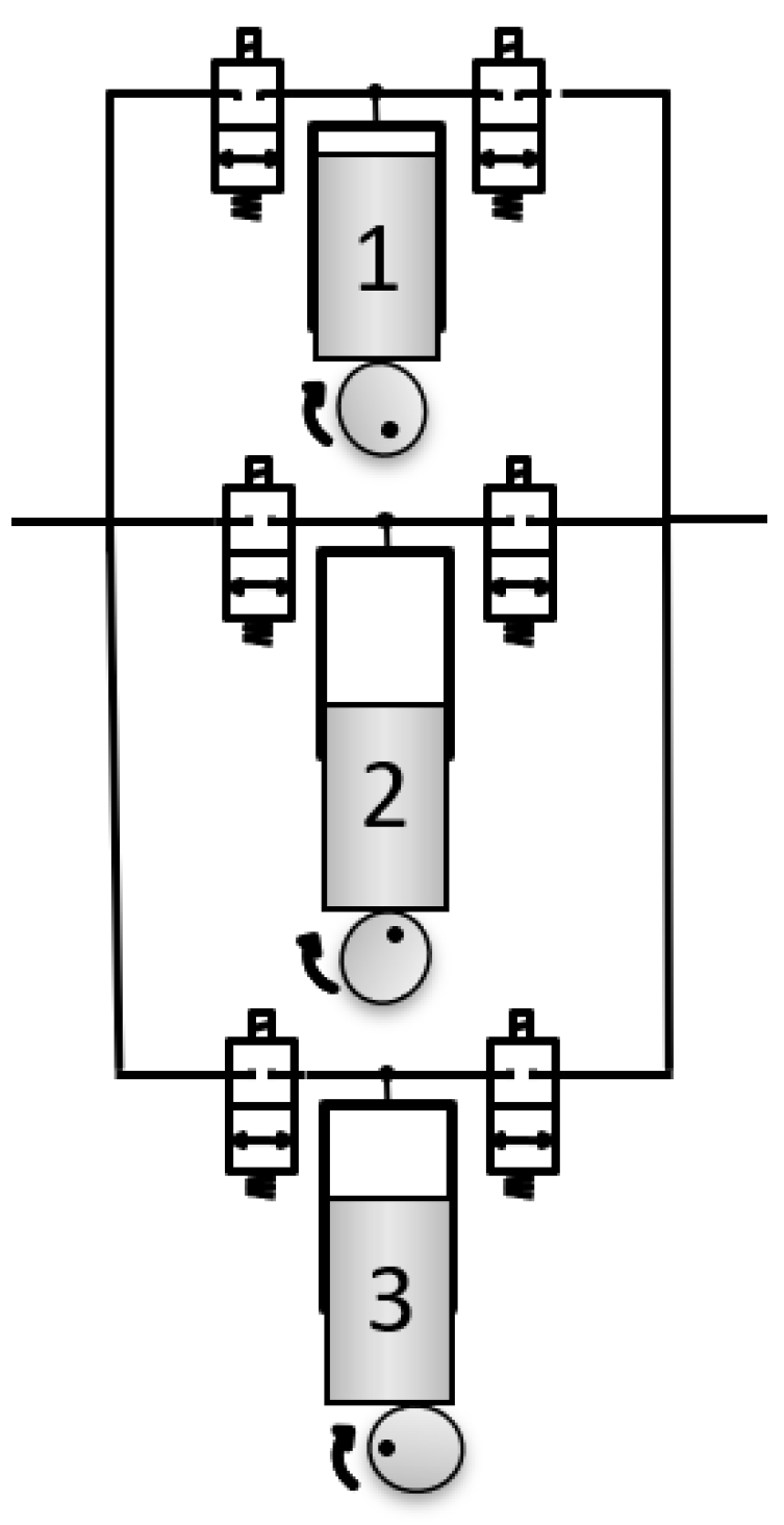
5.1. Internal Mechanical Structure of the Mechanically Actuated Digital Pump

This subsection gives a brief introduction to the mechanical structure of the me-chanically actuated digital pump, which can achieve efficiencies higher than the ones reported in this paper. The internal mechanical structure of the intended digital pump, shown in Figure 5, comprises three main sub-systems: (1) gear-cam unit, (2) cam-follower unit, and the (3) valve manifold. The gear-cam unit utilizes three main half-masking cams, where each cam consists of two sub-cams that are phased relative to one another to allow achieving different cam profiles. This unit is responsible for the phasing mechanism of the camshafts, where it allows varying the cams' orientation relative to the shaft during rotation. The cam-follower unit consists of the three followers, their mount bracket, and the three valves to be actuated via the cam-follower mechanism. This unit allows converting the rotational motion at the cam to a linear motion at the follower and thus controlling the valves’ opening and closing. Therefore, varying the cam profile using the phasing mechanism permits varying the opening and closing of the valves and thus enables achieving variable pump displacement. A detailed description of the mechanical structure and the pumping mechanisms is presented in [65].

5.2. Operating Strategies of the State-of-the-Art Electrically Actuated Digital Pump

The electrically actuated digital variable displacement pump/motor [42] relies on the control flow entering and leaving the displacement chambers. The pump/motor displacement variation can be achieved by controlling the actuation of two on/off valves on the intake and exhaust ports of the pump. The control and timing of the valves’ actuation enable various pumping/motoring operating strategies. Four different operating strategies have been explored and tested [42] utilizing the state-of-the-art digital pump. The four different operating modes are Partial Flow-Diverting (PFD), Partial Flow-Limiting, Sequential Flow-Diverting (SFD), and Sequential Flow-Limiting (SFL). The most efficient operating strategy discovered is the SFL [63]. SFL is a technique that permits the states of each cylinder to be enabled or disabled, sending either 100% or 0% displacement to the output valve, respectively. This method can be used for both pumping and motoring cycles.
An example of a 100% displacement pumping cycle is shown in Figure 6. This cycle achieves similar functionality as the mechanical check valve. During pumping, the intake valve is opened for the entire stroke (A) and closed when the exhaust stroke begins (B). The exhaust valve is then opened and held until the exhaust stroke is completed (C). This transfers 100% of the fluid entering the piston chamber on the intake stroke, disregarding the dead volume in the cylinder.
An example of 0% displacement for pumping is shown in Figure 7. During this cycle, all intake and exhaust valves remain closed for the entire process, allowing the fluid to be compressed and decompressed. As the cylinder begins its intake stroke, the piston starts to decompress the fluid in the dead volume of the cylinder (A) until the cylinder reaches the Bottom Dead Center (B), which allows depressurizing the fluid and creating a partial vacuum in the chamber. Once the piston begins the exhaust stroke (C), the fluid is compressed back to its original state. Since the intake and exhaust valves remained closed during this cycle, 0% displacement is delivered by the cylinder. Thus, this cycle allows the chamber's dead volume fluid to be depressurized and pressurized, and no fluid is delivered to the system.
The partial vacuum created during the intake stroke is called chamber voiding. The chamber voiding phenomenon was experimentally inspected by [66]. It was experimentally proved that the gas created during the chamber voiding phase, i.e., (B), would dissolve entirely as the fluid is re-compressed.
The central concept of this strategy relies on varying the state of the chambers se-quentially to change the ’ump's displacement. To illustrate, a three-piston pump configuration is shown below in Figure 8. To achieve 66% pumping displacement, two chambers (1 & 2) would operate at 100% displacement, while the third chamber (3) would run at 0% displacement.
Sequencing is averaged over various pump revolutions to achieve a wide range of displacements between 0, 33%, 66%, and 100% [42]. As a case in point, to achieve 11.11% displacement, the first cycle of the pump would turn on one cylinder (1) and turn off two cylinders (2 & 3). The following two pump revolutions would sequence all cylinders (1, 2 & 3) off. This operation achieves 1/9th, or 11%, displacement over the three cycles. A ~1% displacement resolution can be achieved by averaging the sequences over 32 shaft revolutions.

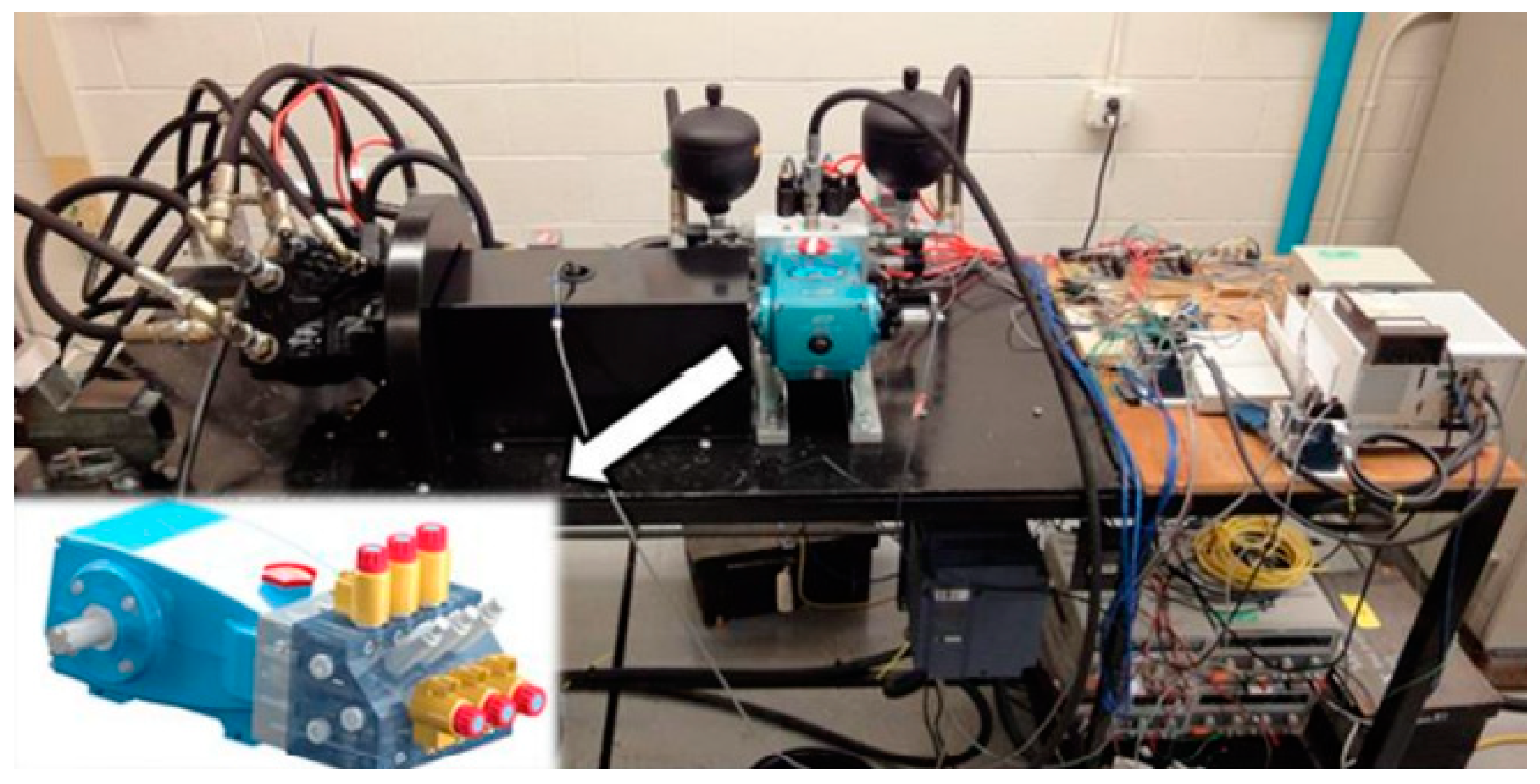
5.3. Experimental Validation of the Electrically Actuated Digital Pump/Motor

The experimental test stand used for testing the SFL operating strategy is shown in Figure 9. The test stand involves the intended 28 cc/rev digital pump, two accumulators (one at the suction side and one at the discharge side), manifold housing with six on/off valves (two for each piston chamber), and other hardware used to complete the hydraulic circuit, data acquisition, and control. The two accumulators were added to the system to reduce pressure and flow ripples and avoid cavitation problems during the suction phase. For instance, if the hydraulic system experienced sudden stops during suction, rapid changes in the system pressure will generate pressure ripples causing shock waves. In this case, the system’s pressure will go above the accumulator’s pre-charged pressure. The accumulator at the discharge port will act as a shock cushioning. It will allow the excessive flow to enter, compressing the gas cushion (nitrogen bladder) and thus cushion and minimize the shock. The second accumulator (one located at the suction port) is required because the pump is bi-directional, i.e., the pump can discharge fluid from either port. A detailed description of the hardware used is presented in [66].
The experimental testing of the SFL pumping/motoring strategy was conducted under steady-state conditions at a temperature T = 50 °C and different pump displacements, 25%, 50%, 75%, and 100% displacement. Moreover, the SFL pumping and motoring cycles were examined at different system pressures ranging from 4 MPa to 18 MPa and shaft speeds up to 700 RPM. Operating the digital pump at shaft speeds beyond 700 RPM requires high-speed switching valves, affecting the valves’ variability and causing non-linearity and errors in the valves’ timing (opening and closing time). A timing valve correction algorithm was developed in [67] and utilized throughout the experimental testing to overcome this problem and account for the valve timing error. The developed algorithm obtains the delay in the valve timing using the pressure readings at the low- and high-pressure ports, thus regulating the valves’ opening and closing time. Although the adopted algorithm enabled high-speed switching, the valves’ opening and closing speeds are not high enough. Thus, the maximum operating shaft speed was limited to 700 RPM throughout the research study.
After executing the experimental testing, the required data (torque, pressure, flow, etc.) were acquired at various pump displacements (25%, 50%, 75%, and 100% displacement), system pressures (4 MPa, 10 MPa, and 18 MPa), and shaft speeds (300 RPM, 500 RPM, and 700 RPM). Then, the efficiencies were calculated according to the obtained data.
The experimental outcomes resulting from operating the SFL strategy at 100% displacement during the pumping and motoring cycles are shown in Figure 10 and Figure 11. Figure 10 illustrates the calculated efficiency curves across various system pressures and shaft speeds at 100% displacement. As shown, at high shaft speeds and low pressures, the pump can achieve efficiencies of at least 78%, while at low shaft speeds and high pressures above 16 MPa, the pump can achieve high efficiencies up to 92%. Furthermore, the system pressure significantly impacts the overall pump's efficiency, where the pump's efficiency significantly increases as pressure increases.
Similarly, the efficiency map corresponding to operating the pump with the SFL strategy at 100% displacement during the motoring mode is shown in Figure 11. As shown in the figure, the motoring mode enables efficiencies of at least 72% and up to 92%. Unlike the results of the pumping mode, in motoring mode, the efficiency curves are almost parallel to the x-axis, which means that the shaft's speed has a negligible impact on the pump's efficiency. For instance, we can still achieve efficiencies from 72% to 92% at any RPM, depending on the system's pressure.

6. Simulation Model: Hydraulic Hybrid Drivetrains Utilizing Digital Pump/Motors

This section presents a physics-based series hydraulic hybrid drivetrain simulation conducted on MATLAB Simscape, a graphical programming software created by MathWorks [68]. The simulated MATLAB Simscape model mimics regular terrain hydraulic vehicles’ series hydraulic hybrid transmission. The goal of the model is to investigate the improvement of the hydraulic hybrid transmission performance after replacing the conventional pump/motors with the digital pump/motor units. The intended state-of-the-art digital units are emulated by applying the digital motoring/pumping data acquired at the tested displacements (25%, 50%, 75%, and 100% displacement), pressures (4 Mpa, 10 MPa, and 18 MPa), and shaft speeds (300 RPM, 500 RPM, and 700 RPM) to the physical simulation components (pump and motor). The digital data are applied to the physical components of the simulation model by converting it into lookup tables imported to the physical pump and motor, employed throughout the simulation.
The following sub-sections present the designed circuit schematic, display the simulation model, design, and functionality during the three transmission stages (acceleration, cruising, and braking), and discuss the resulting outcomes.

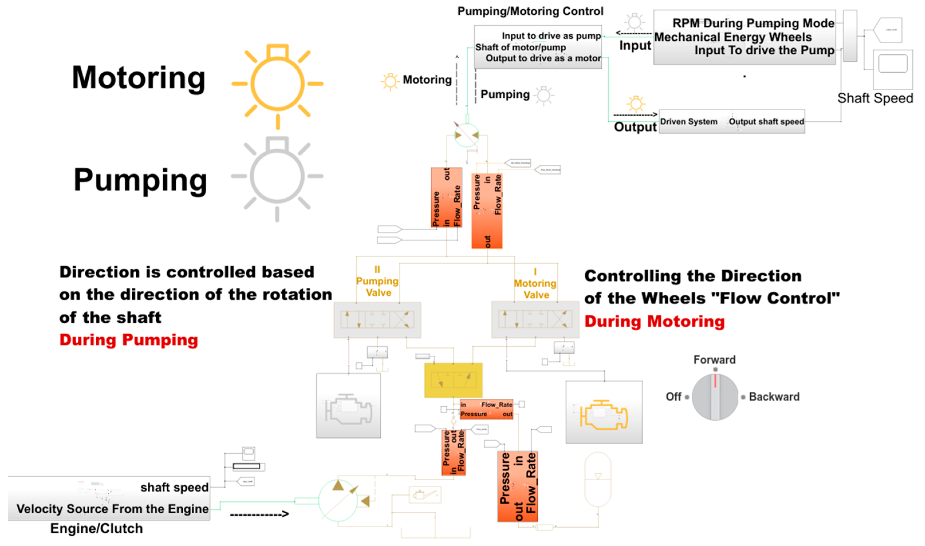
6.1. Circuit Schematics

The adopted series hydraulic transmission, illustrated in Figure 12, comprises a variable displacement pressure compensated pump (5) driven by an electric motor (2), a mechanical clutch (3) to engage and disengage the motor’s shaft from the rest of the system, a pressurized gas accumulator (1) for energy storage-boost purposes, a low-pressure reservoir (8), and a variable displacement pump/motor (11) for power transmission. The pump/motor (11) operates as a motor during acceleration and cruising, i.e., motoring mode, and works as a pump during braking, i.e., pumping mode. A check valve (6) is added to block the backflow (flow from and into the accumulator) from entering the pump’s discharge port. Two 4/3 way (9 & 10) and one 3/2 way (7) directional flow control valves allow a seamless operation during the motoring and pumping modes. The 4/3 way valves (9 & 10) are closed-center valves with spring return having two directly actuated solenoid coils, while the 3/2 way valve (7) is a spring return valve with one actuated solenoid coil. As demonstrated through the simulation model, valve (9) is employed during the motoring mode, i.e., acceleration and cruising, where the user controls the valve based on the direction of motion, i.e., forward or backward drive. However, valve (10) is used during the pumping mode, i.e., regenerative braking, and it is controlled based on the direction of rotation received by the unit’s shaft (11). Valve (7) allows switching between valves (9) and (10) based on the system’s operation mode. During the motoring mode, i.e., acceleration and cruising, valve (7) is set at its un-actuated position, allowing pumping the fluid into the motor (11) through valve (9). However, during the pumping mode, i.e., at braking, the mechanical braking signal will be converted into an electrical signal at valve (7), forcing it to switch to the other position and thus allowing the motor (11) to pump the flow from the tank into the accumulator through the valve (10).

6.2. Simulation Model, Design, and Operation
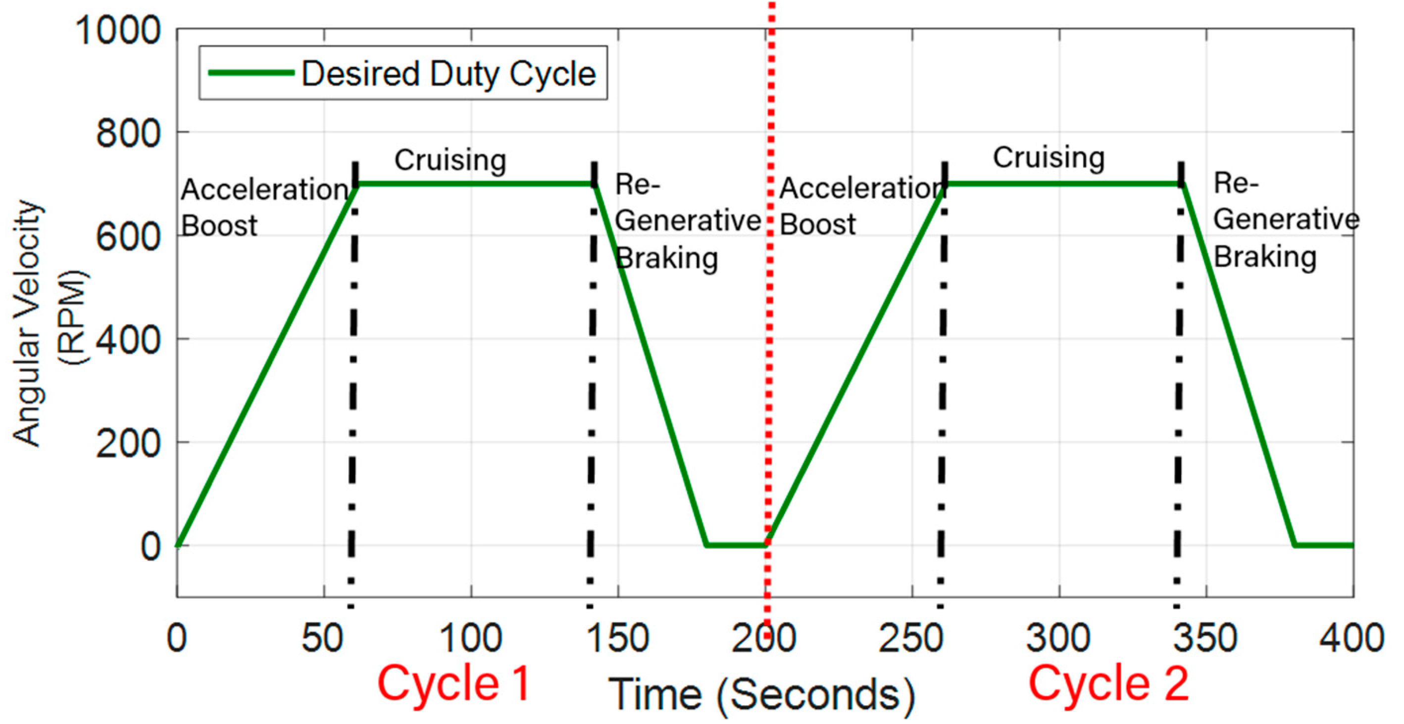
Figure 13 exhibits the physical model for the series hydraulic hybrid transmission illustrated in Figure 12. The adopted system is modeled and simulated using Simscape Fluids and Drivetrains libraries on MATLAB-Simulink. The simulation model is constructed by integrating the required numerical block diagrams with the physical paradigms. All the hydraulic physical components, i.e., pump, motor, valves, and other hydraulic units, are compiled using interfaceable physical connections. The figure shows that the model involves a pressure compensated pump and a variable displacement motor that operates as a motor when pumping high-pressure fluid into one of its ports and as a pump when receiving a mechanical signal at its output shaft. Furthermore, the model involves physical hydraulic sensors to sense the flow and the pressure at specific points in the system. For instance, pressure-flow sensors are installed at the pump’s discharge port, accumulator’s port, and motor’s inlet and outlet ports. The accumulator’s flow sensor is installed into the accumulator. Then, a positive flow rate at the accumulator’s port designates flow into the accumulator; during charging. However, a negative flow denotes flow out of the accumulator; during discharging. Besides the pressure-flow sensors, mechanical sensors, e.g., rotational motion and torque sensors, are added at the pump’s and motor’s shaft to measure the resulting shaft’s speed and torque. Acquiring this data (torque and speed) allowed us to compute the input and output mechanical powers. The power data was then exported into the MATLAB workspace for calculating the average input and output powers. The average input and output powers were individually calculated over the entire cycle using the mean function in MATLAB.
The digital pumping/motoring data presented in Section 5.2 are converted into lookup tables and then imported to the physical pumping/motoring units (the utilized pressure-compensated pump and the variable displacement motor) to incorporate the pre-introduced digital pump/motor. The pumping data is imported into the physical motor (11) during braking as a lookup table. Also, it is imported into the physical pump (5) during cruising, knowing that the pump will be off during acceleration. Similarly, the motoring data is applied to the physical motor as a lookup table during acceleration and cruising. Thus, the physical pump and motor (pressure-compensated pump and the variable displacement motor) are sized based on the imported lookup tables, which allows setting the maximum and minimum pressures in the system in addition to the required flow rate. Then, the accumulator and other hydraulic components, e.g., valves, fittings, hoses, etc., are sized and selected based on the acquired system’s pressure and flow rate. Based on the digital pumping/motoring data, the hydraulic units (5) and (11) will operate between 300 RPM and 700 RPM with a maximum displacement of 28 cc/rev. Furthermore, the hydraulic units will work under a volumetric efficiency up to 94% and overall efficiency of at least 78% and up to 90% during pumping. However, unit (11) will operate during motoring under volumetric and total efficiencies up to 99% and 92%, respectively. Furthermore, the simulation model accounts for the system’s internal losses, e.g., losses in hydraulic pipelines, fittings, and valves. These internal losses are simulated by adding hydraulic resistance, capacitance, and inductance to the distributed parameter model using the simscape block models for hydraulic pipelines, fittings, and hoses.
During the series hydraulic hybrid transmission, the gas accumulator serves as a hydraulic lunch assist device to provide auxiliary flow during high demand requirements (within the acceleration stage), forcing the gas inside the accumulator to expand and compress under adiabatic conditions. Based on the intended application, the accumulator is sized using the following equations [69]:
P 1 V 1 k = P 2 V 2 k
V 1 = V x ( P 3 / P 1 ) 1 / k 1 ( P 3 / P 2 ) 1 / k
where P 1 , P 2 , and P 3 in Pa denote the accumulator’s pre-charged pressure, system maximum operating pressure, and system minimum operating pressure, respectively, set based on the experimentally validated data of the digital pump. V 1 and V 2 in L designate the nitrogen’s volume at P 1 and P 2 , respectively, V x in L denotes the required fluid volume, and k = 1.4 is the nitrogen constant during adiabatic operation. To prevent the accumulator’s poppet (poppet that opens and closes, allowing fluid to enter and leave) from fully closing during the expansion of the nitrogen bladder, the accumulator’s pre-charged pressure P 1 has to be set between 60% to 80% of the minimum system pressure [70,71]. Thus, for P 2 = 1.9e + 7 Pa, P 3 = 5.3e + 6 Pa and P 1 = 0.75 P 3 , we get V 1 = 36.3 L and V x = 18 L.
The adopted physical model comprises two emulation options, options one and two shown in Figure 14, for simulating the intended system. Option one allows for a user interface simulation. The user can interact with the transmission model by switching between the motoring and the pumping modes, thus mimicking the driving and braking situations. Given this option, the user generates the duty cycle by choosing when to drive and brake. On the other hand, option two enables a complete auto-simulation over the three transmission stages (acceleration, cruising, and braking). The simulation will be done automatically based on the provided duty cycle for this option.
Relying on option two, several drive cycles were adopted to test the simulation model’s capability over the three transmission stages. The total time frame of the tested drive cycles ranged from 200 s/cycle to 300 s/cycle, where the acceleration and braking phases required long times up to 60 s and 40 s, respectively. The acceleration and braking timing is due to the accumulator’s charging and discharging time, which was selected based on the experimentally acquired pump data that was limited with a maximum and minimum pressure around 19.1 MPa and 5.3 MPa, respectively.
One of the tested duty cycles is shown in Figure 15. The figure shows that the physical system is simulated for 400 s for two consecutive cycles. Each cycle comprises the three stages of the series hydraulic hybrid transmission (acceleration, cruising, and braking). During the first cycle, the acceleration phase occurs between 0 and 60 s, the cruising starts at time = 60 s and continues until time = 140 s, and the re-regenerative braking takes place within 140 and 180 s. The second cycle starts 20 s after the first cycle, which accounts for the complete stopping of the vehicle. Similarly, the three transmission stages (acceleration, cruising, and braking) occur for 60, 80, and 40 s, respectively, during the second cycle.
To fully simulate the hydraulic hybrid series transmission system for achieving the desired duty cycle in Figure 15, it is required to apply the desired operating angular velocity at the system’s input port and specify its load. The system’s operating RPM is simulated by applying an input signal builder using a physical velocity source. The transmission’s total mass was included within the physical paradigms of the utilized hydraulic units and all components in the Simscape environment. The transmission’s load is simulated using four Simscape Tire blocks, which simulate the tires by their radius and ideal inertia. In [72], Valeski approximates the average tire’s weight and diameter to be around 10 kg and 40 cm, respectively. Thus, the calculated moment of inertia on each tire was around 0.37 kg·m2. Given the calculated moment of inertia on each tire, a moderate physical torque source with an ideal moment of inertia of 1.5 kg·m2 was applied at the motor’s shaft. Now, we explain the operation of the simulation model during each stage.

6.2.1. Acceleration

During acceleration, the accumulator is fully-charged with pressurized fluid, and its pre-charged pressure is greater than the system’s operating pressure. At this phase, the pump is off, and thus the accumulator acts as an auxiliary power supply. The accumulator discharges its stored energy into the motor (11), operating in its motoring mode, to accelerate the vehicle. The valves’ opening/closing operation is controlled based on the accumulator’s pre-charged pressure. For instance, during this phase, because the pre-charged pressure of the nitrogen inside the accumulator is greater than the system’s pressure, no signal is generated at the valve (7). Then, valve (7) is kept at its un-actuated position to pass the flow through the valve (9) and block it at valve (10).

6.2.2. Cruising

At the end of the acceleration phase, the fluid inside the accumulator starts decreasing, and the pre-charged pressure becomes below the system’s pressure. Namely, the accumulator discharged almost all its stored energy, and thus the system requires an additional hydraulic power supply to drive the wheels. At this stage (cruising), the drop in the pre-charged pressure triggers an electric signal at the engine and forces the clutch to engage the engine to the rest of the system. The pump starts pumping the fluid from the low-pressure reservoir (hydraulic tank) into the hydraulic motor (11) that is still operating as a motor to execute the motion at the wheels. Like the acceleration phase, the fluid is delivered to the motor through the valve (9), where valve (10) is still closed.

6.2.3. Braking

During braking, the motor (11) switches to the pumping mode, and the clutch decouples the engine from the rest of the system, forcing the pump (5) to shut down. The pre-charged pressure of the nitrogen gas inside the accumulator drops below the system’s pressure. At this stage, an electric signal is triggered at valve (7), forcing it to switch to the second position and thus pumping the fluid through valve 10 and blocking it at valve 9. The motor utilizes the braking kinetic energy at its output shaft to pump fluid from the tank into the accumulator converting the mechanical energy into hydraulic energy stored in the accumulator to be delivered during acceleration.

7. Resulting Outcomes

After introducing the simulation model and discussing its fundamental operation, throughout the following sections: Section 7.1 and Section 7.2, we present the simulation outcomes resulting from applying the digital motoring/pumping data into units (5) and (11) at moderate load-speed conditions (1.5 kg·m2 and 700 RPM).

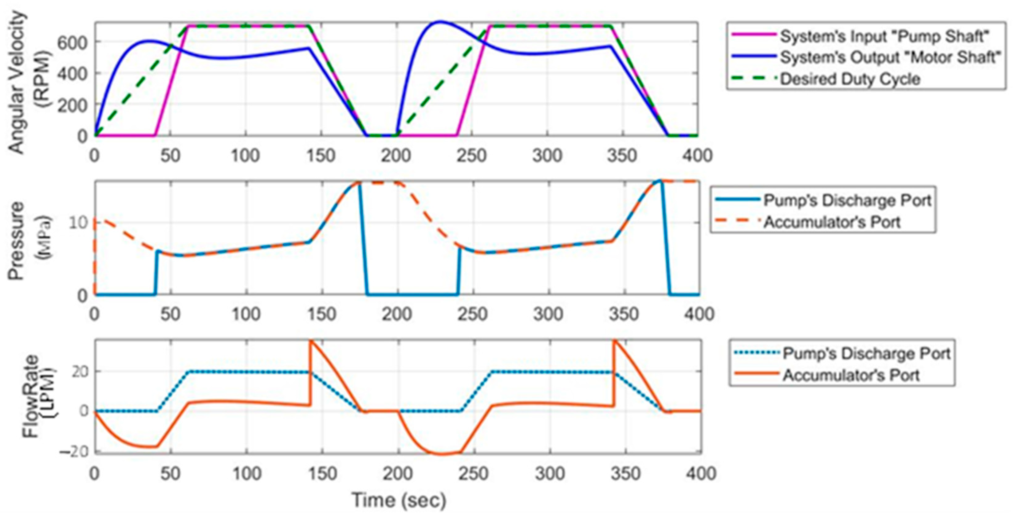
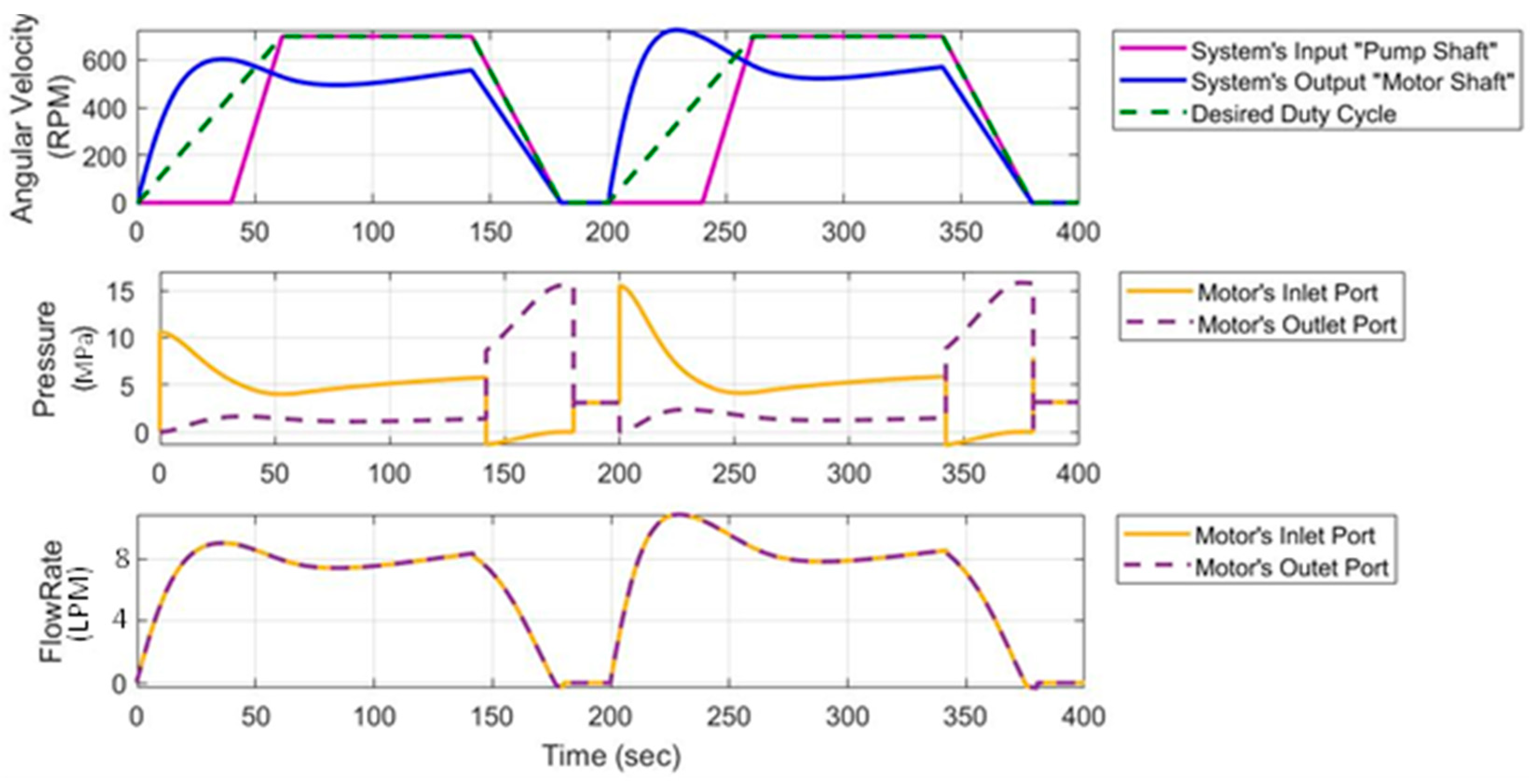
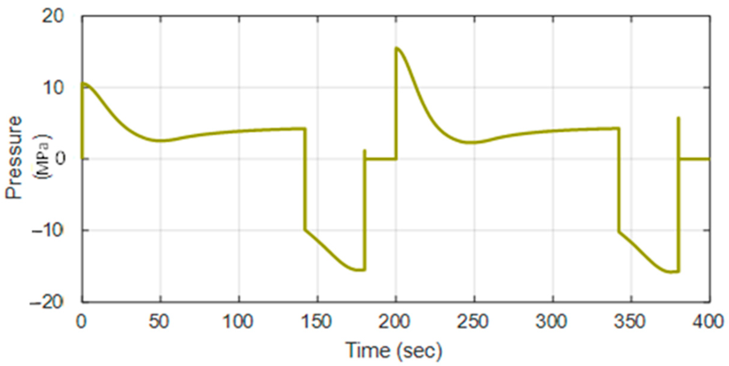
7.1. Pressure-Flow Outcomes

Figure 16 and Figure 17 illustrate the variations in the system’s pressure and flow throughout the proposed duty cycle. They show the pressure-flow outcomes at different ports in the system during the three transmission stages (acceleration, cruising, and braking). As shown in the figures, during the acceleration phase (0 to 60 s in cycle one and 200 to 260 s in cycle two), the pump’s shaft angular velocity is kept at zero, then triggered after 40 s. The pump started operating after 40 s because the accumulator had enough stored energy at the start of the acceleration phase (from 0 to 40 s). Thus, the clutch disengages the engine’s shaft from the pump’s shaft, causing a zero RPM at the pump’s input shaft. The accumulator acts as a hydraulic launch assist and discharges its stored energy into the motor. Thus, the flow rate at the accumulator’s port flows in the negative direction, i.e., from the accumulator into the system, as shown in Figure 16. A pressure drop of about 10 MPa is created between the motor’s inlet and outlet ports, as shown in Figure 17, allowing it to convert the hydraulic energy into mechanical energy enabling the wheels to accelerate until the output shaft speed reaches 600 RPM. As the accumulator delivers the auxiliary power, the fluid’s pressure at the accumulator’s port, shown in Figure 16, decreases because the accumulator’s poppet is still open to deliver fluid to the system. After the accumulator discharges about 80% to 85% of its stored energy, i.e., at time = 40 s, the pump starts operating via the clutch-engine mechanism maintaining the system’s output angular velocity at about 600 RPM, where its discharge pressure, captured in Figure 16, increases up to 6–7.5 MPa. After 20 s, at time = 60 s, the vehicle undergoes the cruising stage. The pump operates at its maximum speed (700 RPM) with an operating pressure of around 7.5 to 8 MPa. The motor’s output shaft operates at almost moderate speed (500 RPM). During this stage, the pressure at the accumulator’s port, shown in Figure 16, is the same as the system’s pressure because the accumulator’s poppet is closed. Thus, the accumulator is neither charging nor discharging. After 80 s, the vehicle undergoes the braking phase, in which the clutch starts disengaging the engine shaft from the pump shaft resulting in a decrease in its RPM. The motor (11) switches to its pumping mode during this phase, pumping the fluid from the tank into the accumulator. The pressure at the motor’s outlet port, shown in Figure 17, increases up to 17.5 MPa causing a high pressure at the accumulator’s port and the pump’s discharge port, shown in Figure 16. The accumulator starts charging, where its flow rate, shown in Figure 16, flows in the positive direction, i.e., from the system into the accumulator.
Figure 18 and Figure 19 show the variations in the accumulator’s fluid volume and the motor’s pressure drop, respectively, throughout the desired duty cycle for the three transmission stages (acceleration, cruising, and braking). As discussed previously, during the acceleration phase, the accumulator discharges its stored energy into the motor’s inlet port to accelerate the motion at the wheels. Thus, the motor operates in its motoring mode. The accumulator’s discharging process causes a decrease in fluid volume, shown in Figure 18, and a positive pressure drop of about 10 MPa at the motor, shown in Figure 19. As shown in Figure 19, the 10 MPa pressure drop across the motor slightly decreases until 5–6.5 MPa. Then, because the accumulator is neither charging nor discharging during the cruising phase, its fluid volume, shown in Figure 18, is kept almost constant. During this phase, the pressure drop across the motor, shown in Figure 19, is maintained at around 7.5 MPa. During braking, the accumulator’s fluid volume, shown in Figure 18, increases because the accumulator is charging. A negative pressure drop is created across the motor, as shown in Figure 19, where the motor is operating in its pumping mode.

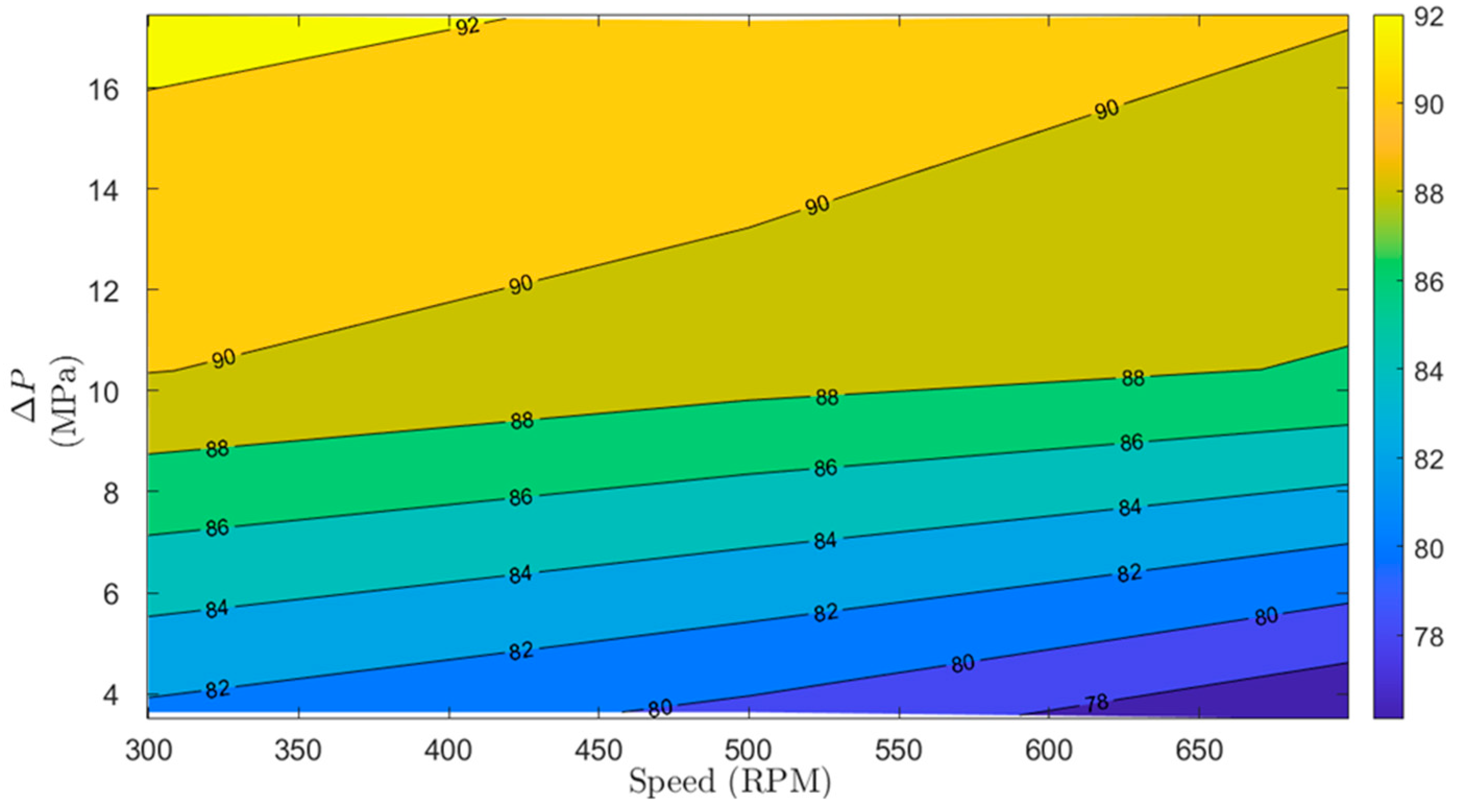
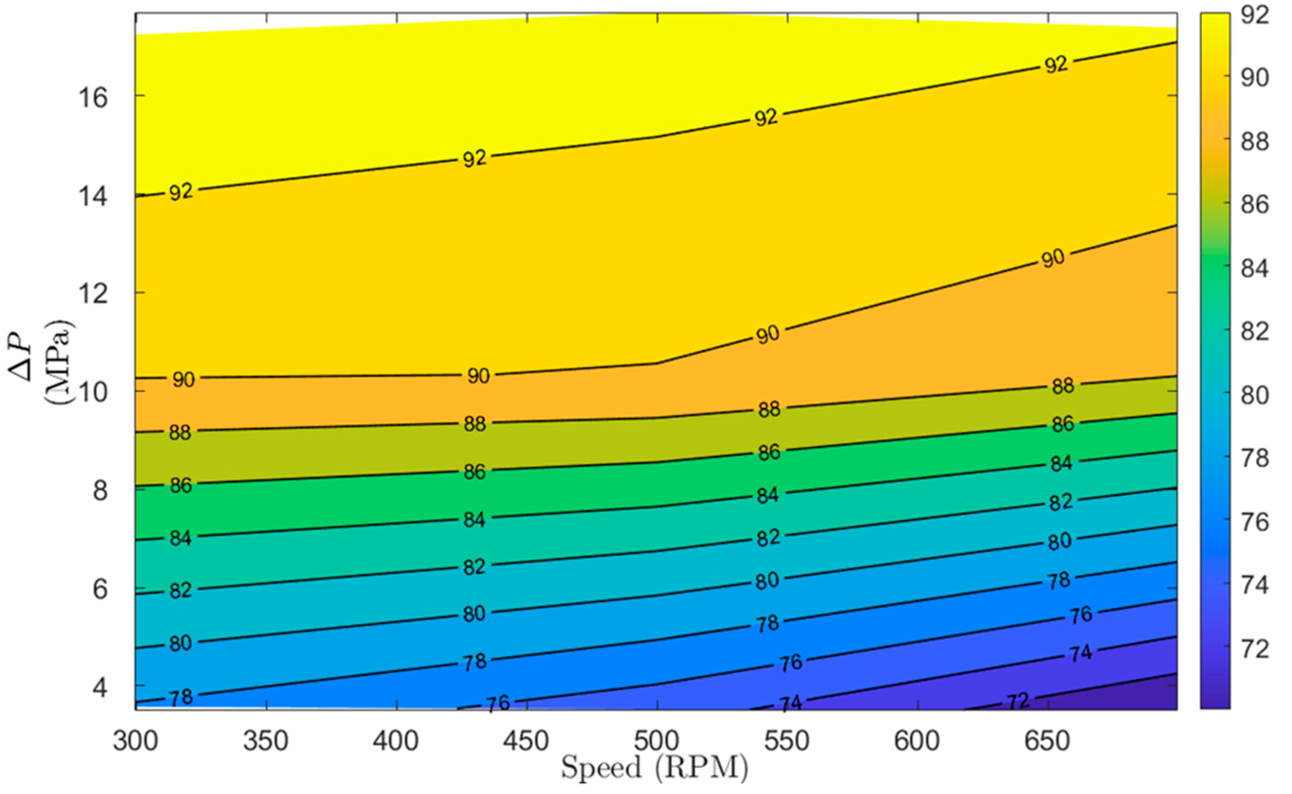
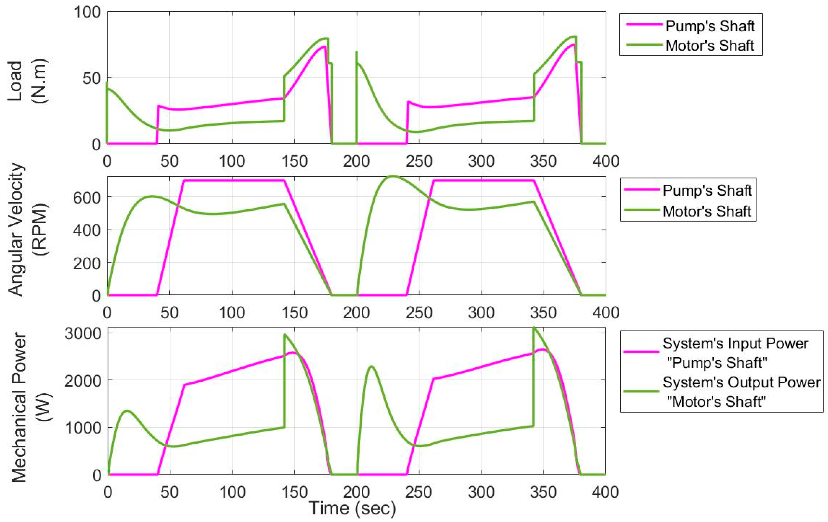
7.2. Power-Efficiency Outcomes

Figure 20 shows the load-speed outcomes and the resulting mechanical power at the pump and motor shafts, i.e., the system’s input and output shafts, respectively, throughout the three transmission stages (acceleration, cruising, and braking). During acceleration, the pump is not operating, and thus the accumulator is the only power supply in the system. The accumulator discharges its stored energy into the motor. The motor converts the hydraulic energy into mechanical energy resulting in an output mechanical power of around 1300 W in cycle one and about 2000 W in cycle two. The difference in the mechanical powers in cycles one and two is due to the accumulator’s initial stored energy. During cruising, the pump starts operating at around 700 RPM, producing an input mechanical power of about 2100 W. This results in an output mechanical power of around 1000 W at the motor’s shaft due to the 1.5 kg⋅m2 inertia added at the wheels. During braking, the motor switches to its pumping mode. It utilizes the braking energy and converts it into hydraulic energy stored in the accumulator.
Simulating the system to achieve the desired duty cycle at moderate load-speed conditions (1.5 kg⋅m2 and 700 RPM) results in average input power of 876 W at the system’s input shaft. This results in an average output power of 780 W at the system’s output shaft, which outputs an overall efficiency of around 89%. This result reveals a significant improvement in the efficiency of the series hydraulic hybrid drivetrains. Due to the rated efficiency of the conventional hydraulic pump/motors, the total average efficiency of the series hydraulic hybrid transmission is around 64% to 81%, which is relatively low [47]. Therefore, the utilization of the state-of-the-art multi-piston digital pump reinforced the system’s performance by increasing the overall efficiency at least 8% and up to 25%.

8. Conclusions

The overall average efficiency of series hydraulic hybrid drivetrains is comparatively low, between 64% and 81%, due to the utilization of conventional variable displacement pumps that become inefficient when operating at partial displacements. This work estimates and addresses the efficiency improvement of a series hydraulic hybrid transmission by integrating hydraulic hybrid technology with digital hydraulics. It proposes replacing the conventional piston pump/motor employed in series hydraulic hybrid drivetrains with the multi-piston digital pump designed and implemented in preceding works. The proposed methodology is tested by conducting a physical-based simulation of a series hydraulic hybrid drivetrain on MATLAB Simscape. The state-of-the-art multi-piston digital pump is simulated by applying its digital motoring/pumping data into the power supply units, i.e., pump and motor utilized throughout the simulation model. The adopted simulation model permitted evaluating the performance of the series hydraulic hybrid drivetrain, and it allowed examining the improvement of the system’s overall efficiency. The final simulation outcomes resulted in 89% overall efficiency and thus exceeded the conventional series hydraulic hybrid drivetrain (64% to 81%). This resulting efficiency reveals that the utilization of the state-of-the-art digital pump enables enhancing the total efficiency of the hydraulic hybrid drivetrains by at least 8% and up to 25%. The attained 89% efficiency can also be better enhanced using a more refined digital unit. The digital pump utilized throughout the simulation model was a proof of concept prototype limited to 700 RPM shaft speed. Thus, a refined one would run at a broader range of inputs and achieve even better results. As future work, we aim to transform the proof-of-concept digital pump into a higher-speed refined unit to test the proposed transmission experimentally.

Author Contributions

Conceptualization, F.B. and I.A.; Investigation, J.G.-B. and F.B.; Methodology, I.A. and F.B.; Supervision, J.G.-B. and F.B.; Validation, J.G.-B.; Visualization, I.A. and F.B.; Writing—original draft, I.A., K.P. and J.G.-B.; Writing—review & editing, I.A. and F.B. All authors have read and agreed to the published version of the manuscript.

Funding

This research received no external funding.

Data Availability Statement

The data that support the findings of this study are available on request from the corresponding author, F.B.

Conflicts of Interest

The authors declare no conflict of interest.

References

  1. McCloy, D.; Martin, H.R. Control of Fluid Power: Analysis and Design, 2nd ed.; Ehlh: Chichester, UK, 1980; Available online: https://ui.adsabs.harvard.edu/abs/1980ehlh.book.....M/abstract (accessed on 10 October 2021).
  2. Durfee, W.; Sun, Z. Fluid Power System; A National Science Foundation Engineering Research Center: Minneapolis, MN, USA, 2009; pp. 1–48.
  3. Vacca, A. Energy Efficiency and Controllability of Fluid Power Systems. Energies 2018, 11, 1169. [Google Scholar] [CrossRef] [Green Version]
  4. Konami, S.; Nishiumi, T. Hydraulic Control Systems; John Wiley & Sons: Singapore, 2016; pp. 187–299. [Google Scholar] [CrossRef]
  5. Fabis-Domagala, J.; Domagala, M.; Momeni, H. A Concept of Risk Prioritization in FMEA Analysis for Fluid Power Systems. Energies 2021, 14, 6482. [Google Scholar] [CrossRef]
  6. What is Fluid Power? National Fluid Power Association. 2021. Available online: https://www.nfpa.com/home/AboutNFPA/What-is-Fluid-Power.htm (accessed on 1 December 2021).
  7. U.S. Fluid Power Industry Brief. 2021. Available online: https://www.nfpa.com/home/industry-stats/Industry-Brief.htm (accessed on 1 December 2021).
  8. Love, L.; Lanke, E.; Alles, P. Estimating the Impact (Energy, Emissions and Economics) of the US Fluid Power Industry. In Oak Ridge National Laboratory (Issue December). 2012. Available online: http://www.osti.gov/servlets/purl/1061537/ (accessed on 1 December 2021).
  9. Kwon, H.; Sprengel, M.; Ivantysynova, M. Thermal modeling of a hydraulic hybrid vehicle transmission based on thermodynamic analysis. Energy 2016, 116, 650–660. [Google Scholar] [CrossRef]
  10. Stelson, K.A.; Meyer, J.J.; Alleyne, A.G.; Hencey, B. Optimization of a passenger hydraulic hybrid vehicle to improve fuel economy. Proc. JFPS Int. Symp. Fluid Power 2008, 2008, 143–148. [Google Scholar] [CrossRef] [Green Version]
  11. Chen, J.-S. Energy Efficiency Comparison between Hydraulic Hybrid and Hybrid Electric Vehicles. Energies 2015, 8, 4697–4723. [Google Scholar] [CrossRef] [Green Version]
  12. Gary, J. Hydrid Transmission. Acad. Manag. Rev. 2006, 31, 386–408. [Google Scholar]
  13. Zhang, Z.; Chen, J.; Wu, B. The control strategy of optimal brake energy recovery for a parallel hydraulic hybrid vehicle. Proc. Inst. Mech. Eng. Part D J. Automob. Eng. 2012, 226, 1445–1453. [Google Scholar] [CrossRef]
  14. Rydberg, K.-E. Energy Efficient Hydraulic Hybrid Drives. In Proceedings of the 11th Scandinavian International Conference on Fluid Power, SICFP’09, Linköping, Sweden, 2–4 June 2009. [Google Scholar]
  15. Tvrdić, V.; Podrug, S.; Šuljić, I.; Matić, B. Hydraulic hybrid vehicle configurations and comparison with hybrid electric vehicle. In Proceedings of the Comtemporary Issues in Economy & Technology—CIET 2018, Split, Croatia, 1–2 June 2018; pp. 548–556. [Google Scholar]
  16. Florida, N.; López, C.; Pocomucha, V. CORE View metadata, citation and similar papers at core. ac. uk. J. Dedik. Pendidik. 2012, 2, 35–43. [Google Scholar]
  17. Shan, M. Modeling and Control Strategy for Series Hydraulic Hybrid Vehicles. Ph.D. Thesis, The University of Toledo, Toledo, OH, USA, December 2009. [Google Scholar]
  18. Tavares, F.; Johri, R.; Salvi, A.; Baseley, S.; Filipi, Z. Hydraulic Hybrid Powertrain-In-the-Loop Integration for Analyzing Real-World Fuel Economy and Emissions Improvements. SAE Technical Paper. 2011. Available online: https://doi.org/10.4271/2011-01-2275 (accessed on 20 October 2021).
  19. Midgley, W.; Cebon, D. Comparison of regenerative braking technologies for heavy goods vehicles in urban environments. Proc. Inst. Mech. Eng. Part D J. Automob. Eng. 2012, 226, 957–970. [Google Scholar] [CrossRef]
  20. Li, C.-T.; Peng, H. Optimal configuration design for hydraulic split hybrid vehicles. In Proceedings of the 2010 American Control Conference, Baltimore, MD, USA, 30 June–2 July 2010; pp. 5812–5817. [Google Scholar] [CrossRef]
  21. Kim, N.; Rousseau, A. A Comparative Study of Hydraulic Hybrid Systems for Class 6 Trucks. SAE Tech. Pap. 2013, 2. [Google Scholar] [CrossRef]
  22. Sprengel, M.; Bleazard, T.; Haria, H.; Ivantysynova, M. Implementation of a Novel Hydraulic Hybrid Powertrain in a Sports Utility Vehicle. IFAC-PapersOnLine 2015, 48, 187–194. [Google Scholar] [CrossRef]
  23. Bottiglione, F.; Mantriota, G.; Valle, M. Power-Split Hydrostatic Transmissions for Wind Energy Systems. Energies 2018, 11, 3369. [Google Scholar] [CrossRef] [Green Version]
  24. Jae, Y.; Filipi, Z.; Kim, Y.J.; Filipi, Z. Simulation Study of a Series Hydraulic Hybrid Prop System for a Light Truck. SAE Trans. 2021, 116, 147–161. [Google Scholar]
  25. Hui, S.; Junqing, J. Research on the system configuration and energy control strategy for parallel hydraulic hybrid loader. Autom. Constr. 2010, 19, 213–220. [Google Scholar] [CrossRef]
  26. Zhou, S.; Walker, P.; Tian, Y.; Zhang, N. Mode switching analysis and control for a parallel hydraulic hybrid vehicle. Veh. Syst. Dyn. 2020, 59, 928–948. [Google Scholar] [CrossRef]
  27. Sim, T.P.; Li, P.Y. Analysis and Control Design of a Hydro-Mechanical Hydraulic Hybrid Passenger Vehicle. In Proceedings of the Dynamic Systems and Control Conference, Hollywood, CA, USA, 12–14 October 2009; pp. 667–674. [Google Scholar] [CrossRef] [Green Version]
  28. Cheong, K.L. Design and Analysis of Hydraulic Hybrid Passenger Vehicles. Ph.D. Thesis, University of Minnesota, Minneapolis, MN, USA, 2015. [Google Scholar]
  29. Ramdan, M.I.; A Stelson, K. Optimal design of a power-split hybrid hydraulic bus. Proc. Inst. Mech. Eng. Part D J. Automob. Eng. 2016, 230, 1699–1718. [Google Scholar] [CrossRef]
  30. Sprengel, M.; Ivantysynova, M. Recent Developments in a Novel Blended Hydraulic Hybrid Transmission. SAE Tech. Pap. 2014, 2014. [Google Scholar] [CrossRef]
  31. Stecki, J.; Matheson, P. Advances In Automotive Hydraulic Hybrid Drives. Proc. JFPS Int. Symp. Fluid Power 2005, 2005, 664–669. [Google Scholar] [CrossRef] [Green Version]
  32. Matheson, P.; Stecki, J. Development and simulation of a hydraulic-hybrid powertrain for use in commercial heavy vehicles. SAE Tech. Pap. 2003, 112, 114–123. [Google Scholar] [CrossRef]
  33. Wu, B.; Lin, C.-C.; Filipi, Z.; Peng, H.; Assanis, D. Optimal Power Management for a Hydraulic Hybrid Delivery Truck. Veh. Syst. Dyn. 2004, 42, 23–40. [Google Scholar] [CrossRef]
  34. Van Batavia, B.L. Hydraulic Hybrid Vehicle Energy Management System; SAE Technical Paper; SAE International: Warrendale, PA, USA, 2009. [Google Scholar] [CrossRef]
  35. Achten, P.A.J.; Schellekens, M.P.A.; Murrenhoff, H.; Deeken, M. Efficiency and Low Speed Behavior of the Floating Cup Pump. J. Commer. Veh. 2004, 113, 366–376. [Google Scholar] [CrossRef]
  36. Buchwald, P.; Christensen, G.; Larsen, H.; Sunn Pedersen, P. Improvement of citybus fuel economy using a hydraulic hybrid propulsion system—A theoretical and experimental study. SAE Tech. Pap. 1979, 88, 1042–1056. [Google Scholar] [CrossRef]
  37. Hydraulic Launch Assist. 2013. Available online: https://www.eaton.com/SEAsia/ProductsSolutions/Hydraulics/ProductsServices/HydraulicLaunchAssist/index.htm (accessed on 1 October 2021).
  38. Tollefson, S.; Beachley, N.H.; Fronczak, F.J. Studies of an Accumulator Energy-Storage Automobile Design with a Single Pump/Motor Unit. SAE Trans. 1985. [Google Scholar] [CrossRef]
  39. Kepner, R.P. Hydraulic power assist—A demonstration of Hydraulic Hybrid Vehicle regenerative braking in a road vehicle application. SAE Tech. Pap. 2002, 111, 826–833. [Google Scholar] [CrossRef]
  40. Bozic, A. Introducing Hydraulic-Electric Synergy into Hybrid Transmission Using the Free-piston Engine Technology. In Proceedings of the Commercial Vehicle Engineering Congress and Exhibition and Powertrain & Fluid Systems Conference, Rosemont, IL, USA, 29 October–1 November 2007. [Google Scholar] [CrossRef]
  41. Breidi, F.; Garrity, J.; Lumkes, J. Design and Testing of Novel Hydraulic Pump/Motors to Improve the Efficiency of Agricultural Equipment. Trans. ASABE 2017, 60, 1809–1817. [Google Scholar] [CrossRef]
  42. El-Breidi, F. Investigation of digital pump/motor control strategies. Ph.D. Thesis, Purdue University, West Lafayette, IN, USA, 2016. [Google Scholar]
  43. Yang, H.-Y.; Pan, M. Engineering research in fluid power: A review. J. Zhejiang Univ. A 2015, 16, 427–442. [Google Scholar] [CrossRef] [Green Version]
  44. Merrill, K.J.; Breidi, F.Y.; Lumkes, J. Simulation based design and optimization of digital pump/motors. In Fluid Power Systems Technology; American Society of Mechanical Engineers: New York, NY, USA, 2013. [Google Scholar]
  45. Li, M.; Foss, R.; Stelson, K.A.; Van De Ven, J.D.; Barth, E.J. Design, Dynamic Modeling, and Experimental Validation of A Novel Alternating Flow Variable Displacement Hydraulic Pump. IEEE/ASME Trans. Mechatron. 2019, 24, 1294–1305. [Google Scholar] [CrossRef]
  46. Wilhelm, S.R.; Van De Ven, J.D. Synthesis of a Variable Displacement Linkage for a Hydraulic Transformer. In Proceedings of the International Design Engineering Technical Conferences and Computers and Information in Engineering Conference, Washington, DC, USA, 28–31 August 2011. [Google Scholar] [CrossRef] [Green Version]
  47. Chen, Y.L.; Liu, S.A.; Jiang, J.H.; Shang, T.; Zhang, Y.K.; Wei, W. Dynamic analysis of energy storage unit of the hydraulic hybrid vehicle. Int. J. Automot. Technol. 2013, 14, 101–112. [Google Scholar] [CrossRef]
  48. Ivantysynova, M. Innovations in pump design-what are future directions? Proc. JFPS Int. Symp. Fluid Power 2008, 2008, 59–64. [Google Scholar] [CrossRef] [Green Version]
  49. Zhang, C.; Huang, S.; Du, J.; Wang, X.; Wang, S.; Zhang, H. A new dynamic seven-stage model for thickness prediction of the film between valve plate and cylinder block in axial piston pumps. Adv. Mech. Eng. 2016, 8. [Google Scholar] [CrossRef] [Green Version]
  50. Shang, L.; Ivantysynova, M. A temperature adaptive piston design for swash plate type axial piston machines. Int. J. Fluid Power 2016, 18, 38–48. [Google Scholar] [CrossRef]
  51. Rizzo, G.; Massarotti, G.; Bonanno, A.; Paoluzzi, R.; Raimondo, M.; Blosi, M.; Veronesi, F.; Caldarelli, A.; Guarini, G. Axial piston pumps slippers with nanocoated surfaces to reduce friction. Int. J. Fluid Power 2015, 16, 1–10. [Google Scholar] [CrossRef]
  52. Inaguma, Y.; Hibi, A. Reduction of friction torque in vane pump by smoothing cam ring surface. Proc. Inst. Mech. Eng. Part C J. Mech. Eng. Sci. 2007, 221, 527–534. [Google Scholar] [CrossRef]
  53. Wieczorek, U.; Ivantysynova, M. Computer Aided Optimization of Bearing and Sealing Gaps in Hydrostatic Machines—The Simulation Tool Caspar. Int. J. Fluid Power 2002, 3, 7–20. [Google Scholar] [CrossRef]
  54. Sazonov, Y.A.; Mokhov, M.A.; Gryaznova, I.V.; Voronova, V.V.; Tumanyan, K.A.; Frankov, M.A.; Balaka, N.N. Development and Prototyping of Jet Systems for Advanced Turbomachinery with Mesh Rotor. Emerg. Sci. J. 2021, 5, 775–801. [Google Scholar] [CrossRef]
  55. Kostikov, Y.A.; Romanenkov, A.M. Approximation of the Multidimensional Optimal Control Problem for the Heat Equation (Applicable to Computational Fluid Dynamics (CFD)). Civ. Eng. J. 2020, 6, 743–768. [Google Scholar] [CrossRef]
  56. Manring, N.D. Valve-Plate Design for an Axial Piston Pump Operating at Low Displacements. J. Mech. Des. 2003, 125, 200–205. [Google Scholar] [CrossRef]
  57. Helmus, T.; Breidi, F.; Lumkes, J. Simulation of a variable displacement mechanically actuated digital pump unit. In Proceedings of the Eight Workshop on Digital Fluid Power, Tampere, Finland, 24–25 May 2016; pp. 95–106. [Google Scholar]
  58. Chehade, A.; Breidi, F.; Pate, K.S.; Lumkes, J. Data-driven Adaptive Thresholding Model for Real-time Valve Delay Estimation in Digital Pump/Motors. Int. J. Fluid Power 2019, 20, 271–294. [Google Scholar] [CrossRef]
  59. Winkler, B. Recent Advances in Digital Hydraulic Components and Applications. In Proceedings of the The Ninth Workshop on Digital Fluid Power, Aalborg, Denmark, 7–8 September 2017; Available online: https://www.et.aau.dk/digitalAssets/377/377525_id117-recent-advances-in-digital-hydraulic-components-and-applications.pdf (accessed on 1 December 2021).
  60. Brandstetter, R.; Deubel, T.; Scheidl, R.; Winkler, B.; Zeman, K. Digital hydraulics and “Industrie 4.0”. Proc. Inst. Mech. Eng. Part I J. Syst. Control. Eng. 2016, 231, 82–93. [Google Scholar] [CrossRef]
  61. Peng, S.; Branson Iii, D.T.; Guglielmino, E.; Boaventura, T.; Caldwell, D.G. Performance Assessment of Digital Hydraulics in a Quadruped Robot Leg. 2012. Available online: http://asmedigitalcollection.asme.org/ESDA/proceedings-pdf/ESDA2012/44861/227/4451304/227_1.pdf?casa_token=fWco0NtKGfUAAAAA:9c3YrOxP0rRp-PmWLcv8DUFtas4Qe6HnyCq02vGig-lSARq94FAcQnGOpL9W-XpcM-sdwGk (accessed on 5 November 2021).
  62. Pinto, L.P.G.; Belan, H.C.; Locateli, C.C.; Krus, P.; De Negri, V.J.; Lantto, B. New perspectives on digital hydraulics for aerospace applications. In Proceedings of the Aerospace Technology Congress, Solna, Stockholm, 11–12 October 2016. [Google Scholar]
  63. Breidi, F.; Helmus, T.; Lumkes, J. The impact of peak-and-hold and reverse current solenoid driving strategies on the dynamic performance of commercial cartridge valves in a digital pump/motor. Int. J. Fluid Power 2015, 17, 37–47. [Google Scholar] [CrossRef]
  64. Breidi, F.; Chehade, A.; Lumkes, J. Monitoring Digital Technologies in Hydraulic Systems Using CUSUM Control Charts. In Fluid Power Systems Technology; American Society of Mechanical Engineers: New York, NY, USA, 2019. [Google Scholar]
  65. Helmus, T. Investigation and Implementation of Mechanically Actuated Valves for Digital Hydraulic Units. Ph.D. Thesis, Purdue University, West Lafayette, IN, USA, 2017. [Google Scholar]
  66. Holland, M.A. Design of Digital Pump/Motors and Experimental Validation of Operating Strategies Doctor of Philosophy. 2012. Available online: http://www.purdue.edu/policies/pages/teach_res_outreach/c_22.html (accessed on 1 December 2021).
  67. Breidi, F.; Garrity, J.; Lumkes, J., Jr. Investigation of a real-time pressure based valve timing correction algorithm. In Fluid Power Systems Technology; American Society of Mechanical Engineers: New York, NY, USA, 2017. [Google Scholar]
  68. Simscape—MATLAB & Simulink. 2021. Available online: https://www.mathworks.com/products/simscape.html (accessed on 6 October 2021).
  69. Sizing Tool—Reasontek Corp. 2021. Available online: https://www.reasontek.com/sizing-tool/ (accessed on 23 November 2021).
  70. Cheema, J. Air and Oil Do Mix: Selecting the Right Accumulator Is Critical for Wind Farm Applications. Hydraulics and Pneumatic. 2013. Available online: http://ezproxy.derby.ac.uk/login?url=http://search.ebscohost.com/login.aspx?direct=true&db=edsbl&AN=RN332050940&site=eds-live (accessed on 28 November 2021).
  71. Xu, Z.; Li, W.; Liu, X.; Chen, Z. Dynamic characteristics of coupling model of valve-controlled cylinder parallel accumulator. Mech. Ind. 2019, 20, 306. [Google Scholar] [CrossRef]
  72. Valeski, B. Average Tire Weight (With 10 Examples)—Survival Tech Shop. 2021. Available online: https://www.survivaltechshop.com/tire-weight/ (accessed on 1 December 2021).
Figure 1. Schematic for the parallel hydraulic hybrid configuration.
Energies 15 01348 g001
Figure 2. Schematic for the series hydraulic hybrid configuration.
Energies 15 01348 g002
Figure 3. Schematic for the series-parallel hydraulic hybrid configuration.
Energies 15 01348 g003
Figure 4. Single-piston digital pump/motor configuration [64].
Energies 15 01348 g004
Figure 5. CAD drawing showing the basic units of the mechanically actuated digital pump.
Energies 15 01348 g005
Figure 6. Enabled chamber operating at 100% displacement during SFL mode.
Energies 15 01348 g006
Figure 7. Disabled chamber operating at 0% displacement during SFL mode.
Energies 15 01348 g007
Figure 8. Three-piston digital inline piston pump configuration.
Energies 15 01348 g008
Figure 9. The experimental test stand for testing different operating strategies of the electrically actuated digital 3-piston pump [42].
Energies 15 01348 g009
Figure 10. Efficiency map of the electrically actuated digital pump/motor operated in the SFL pumping strategy at 100% displacement.
Energies 15 01348 g010
Figure 11. Efficiency map of the electrically actuated digital pump/motor operated in the SFL motoring strategy at 100% displacement.
Energies 15 01348 g011
Figure 12. A circuit illustrating the simulated series hydraulic hybrid transmission.
Energies 15 01348 g012
Figure 13. A MATLAB Simscape simulation model for the series hydraulic hybrid transmission.
Energies 15 01348 g013
Figure 14. User interface illustrating the functionality of the simulation model.
Energies 15 01348 g014
Figure 15. The desired duty cycle.
Energies 15 01348 g015
Figure 16. The resulting pressure and flow simulation outcomes at the pump’s discharge and accumulator’s ports throughout the desired duty cycle.
Energies 15 01348 g016
Figure 17. The resulting pressure and flow simulation outcomes at the Motor’s inlet and outlet ports throughout the desired duty cycle.
Energies 15 01348 g017
Figure 18. Simulation outcomes for the fluid volume inside the accumulator.
Energies 15 01348 g018
Figure 19. Simulation results for the pressure drop across the motor, i.e., the pressure difference between the inlet and outlet motor’s pressure.
Energies 15 01348 g019
Figure 20. Load-Speed and mechanical power simulation results.
Energies 15 01348 g020
Publisher’s Note: MDPI stays neutral with regard to jurisdictional claims in published maps and institutional affiliations.

