
Analysis of Linear Hybrid Excited Flux Switching Machines with Low-Cost Ferrite Magnets

 , ,
, ,  , and
, and
Abstract
:1. Introduction
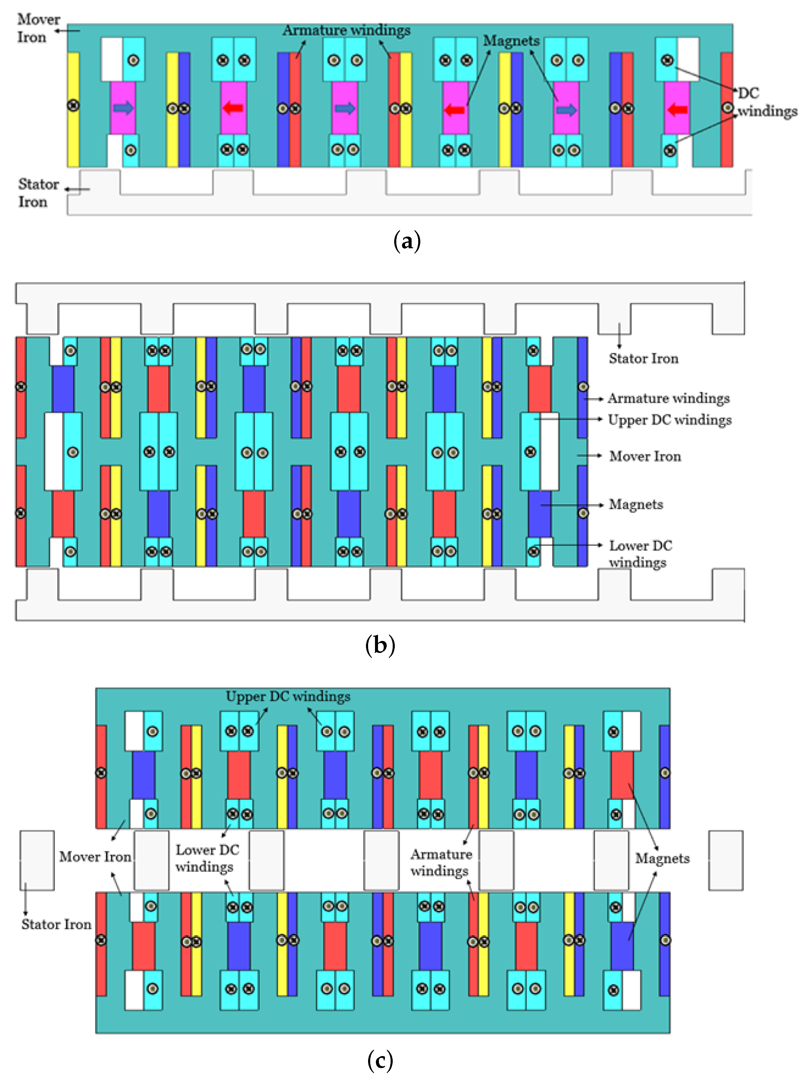
- The primary/mover is equipped with all excitation sources (armature winding, field winding, and PM), which reduces the cost of long stator/secondary windings.
- The machine’s stator is devoid of excitation sources, allowing it to be used in long-stroke applications.
- Ferrite magnets, which minimize expenses, are used. Further, its volume is reduced by 25% compared to conventional designs.
- FEC windings, which add flux regulation capability to proposed designs, are used.
- Double-sided structures are designed and investigated to solve the normal force problem that exists in single-sided structures.
2. Methodology
3. Working Principle
4. Analysis of the Proposed LHEFSM, DSLHEFSM, and DMLHEFSM
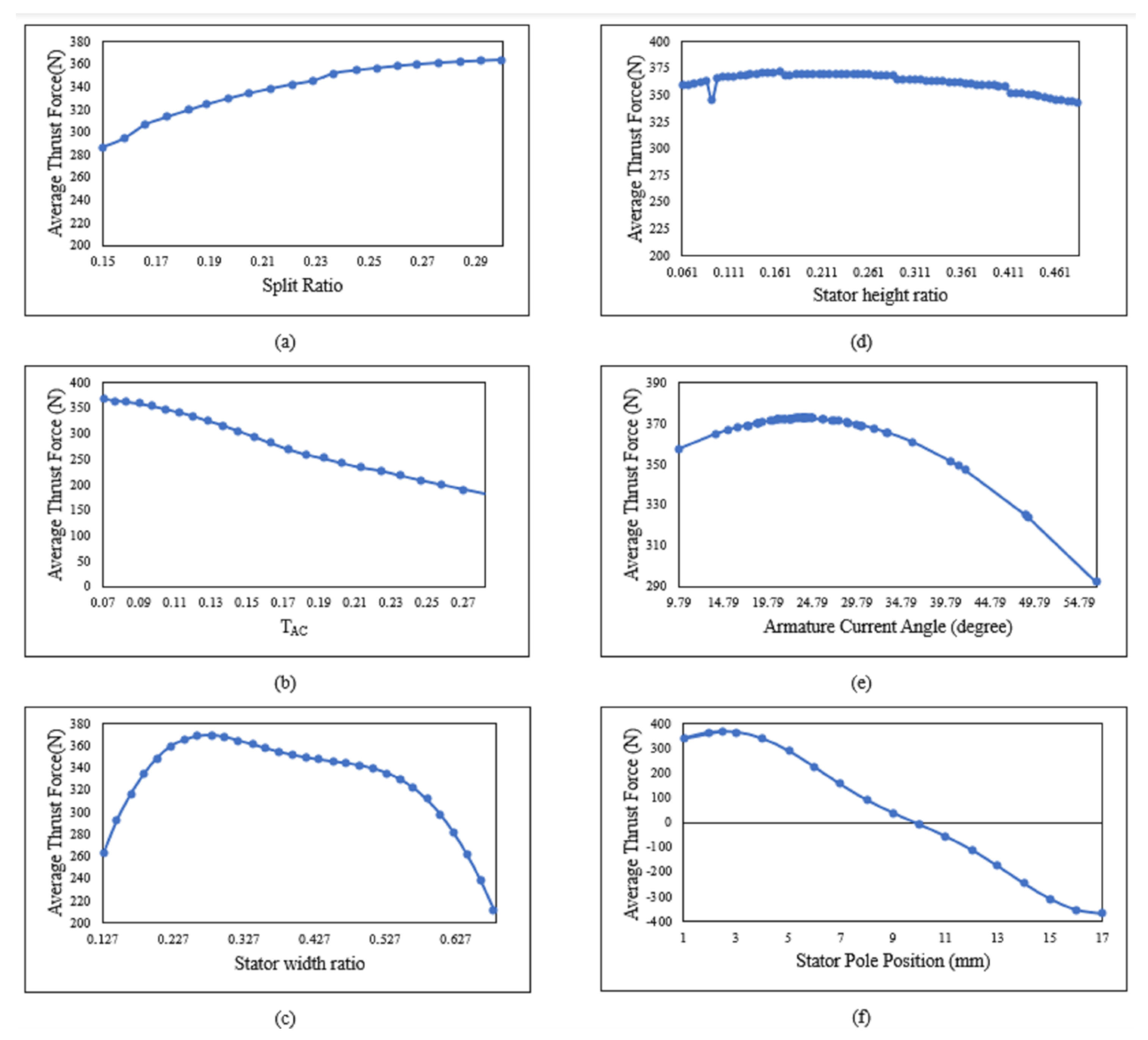
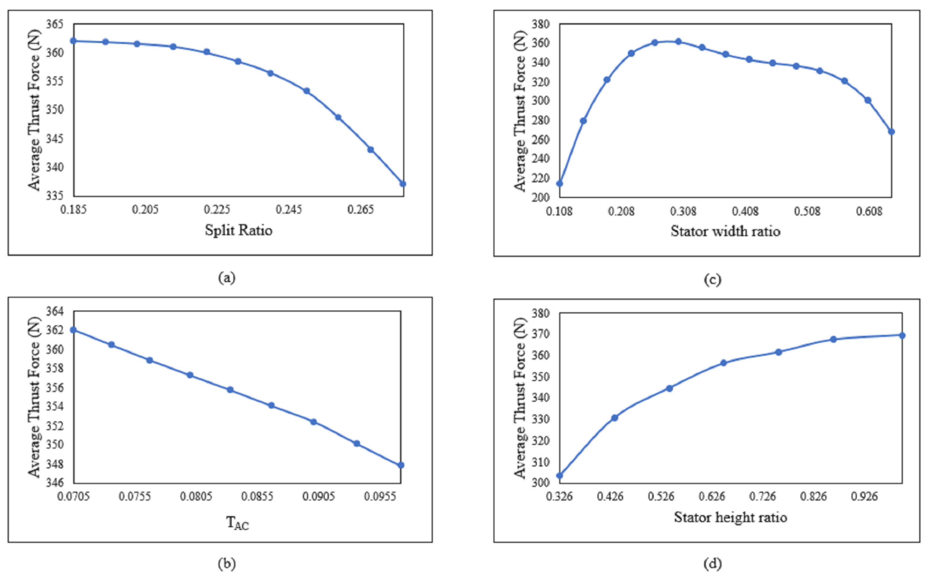
5. Single Variable Optimization
5.1. Optimization of the LHEFSM
5.2. Optimization of the DSLHEFSM
5.3. Optimization of DMLHEFSM
6. FEA Based Results
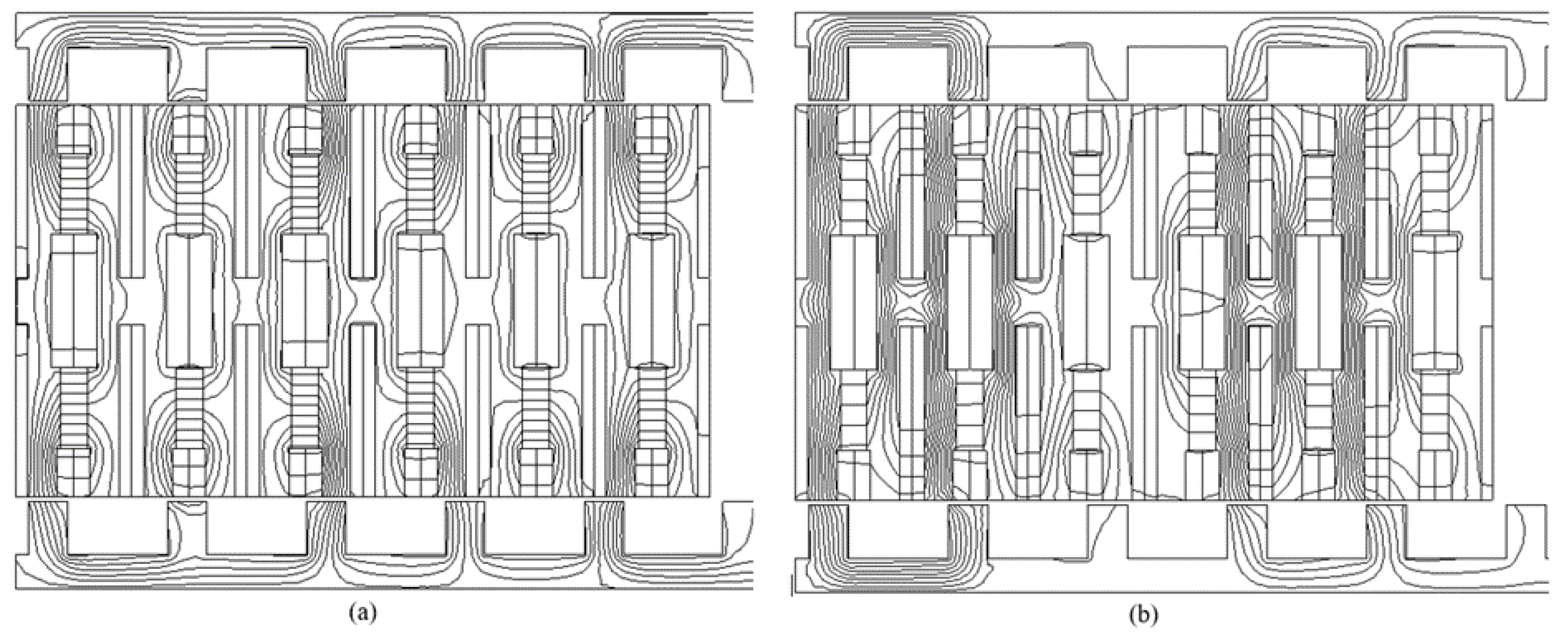
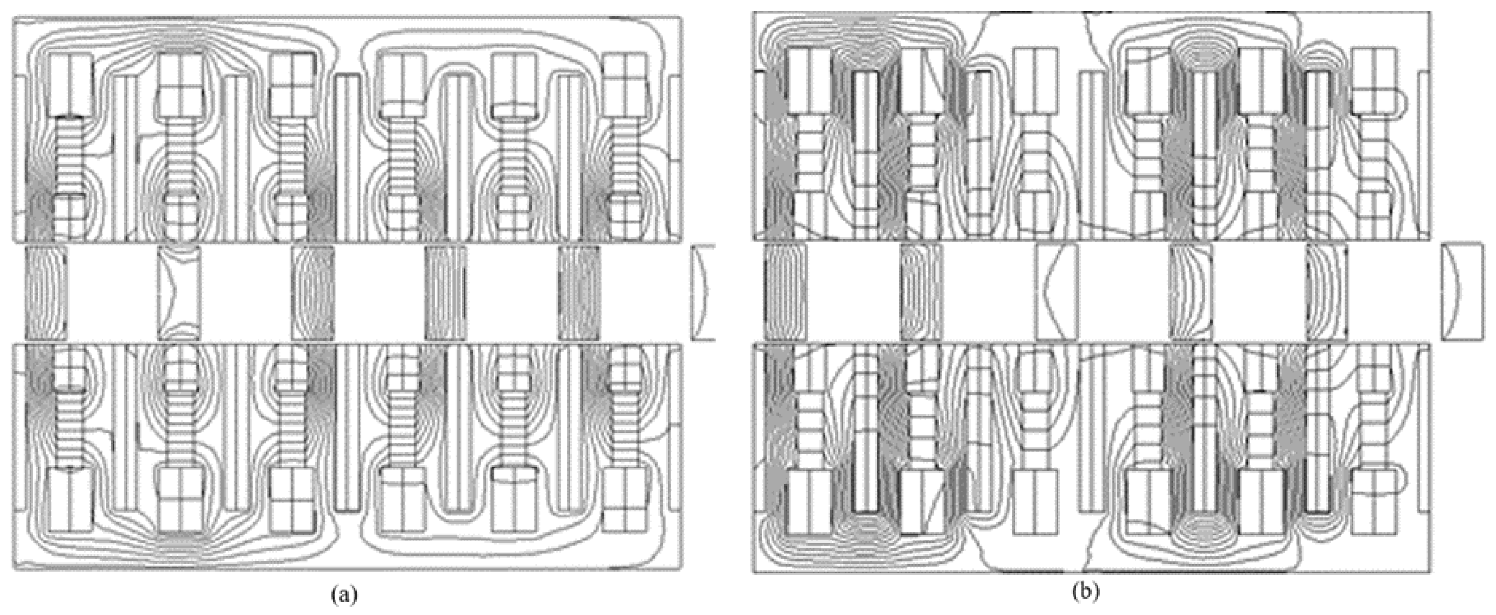
6.1. Flux Distribution
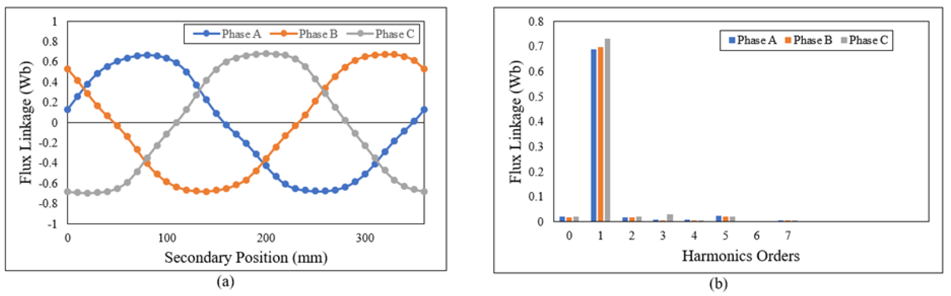
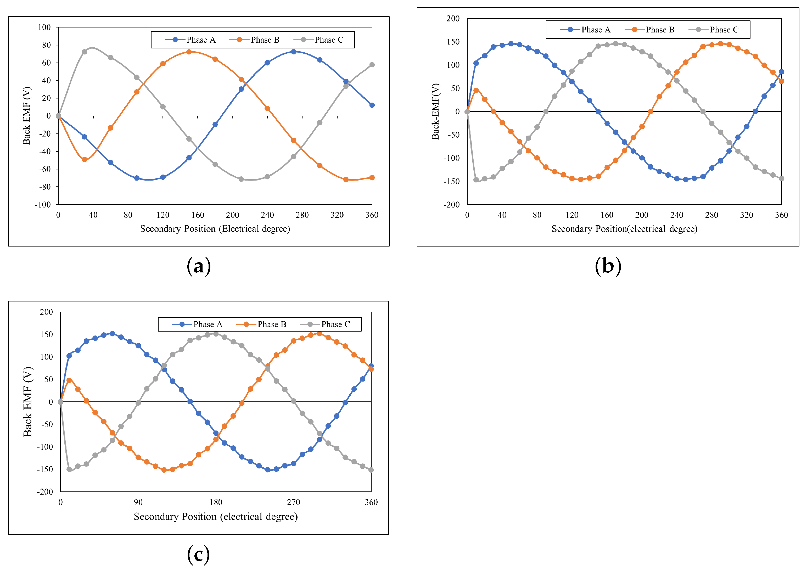
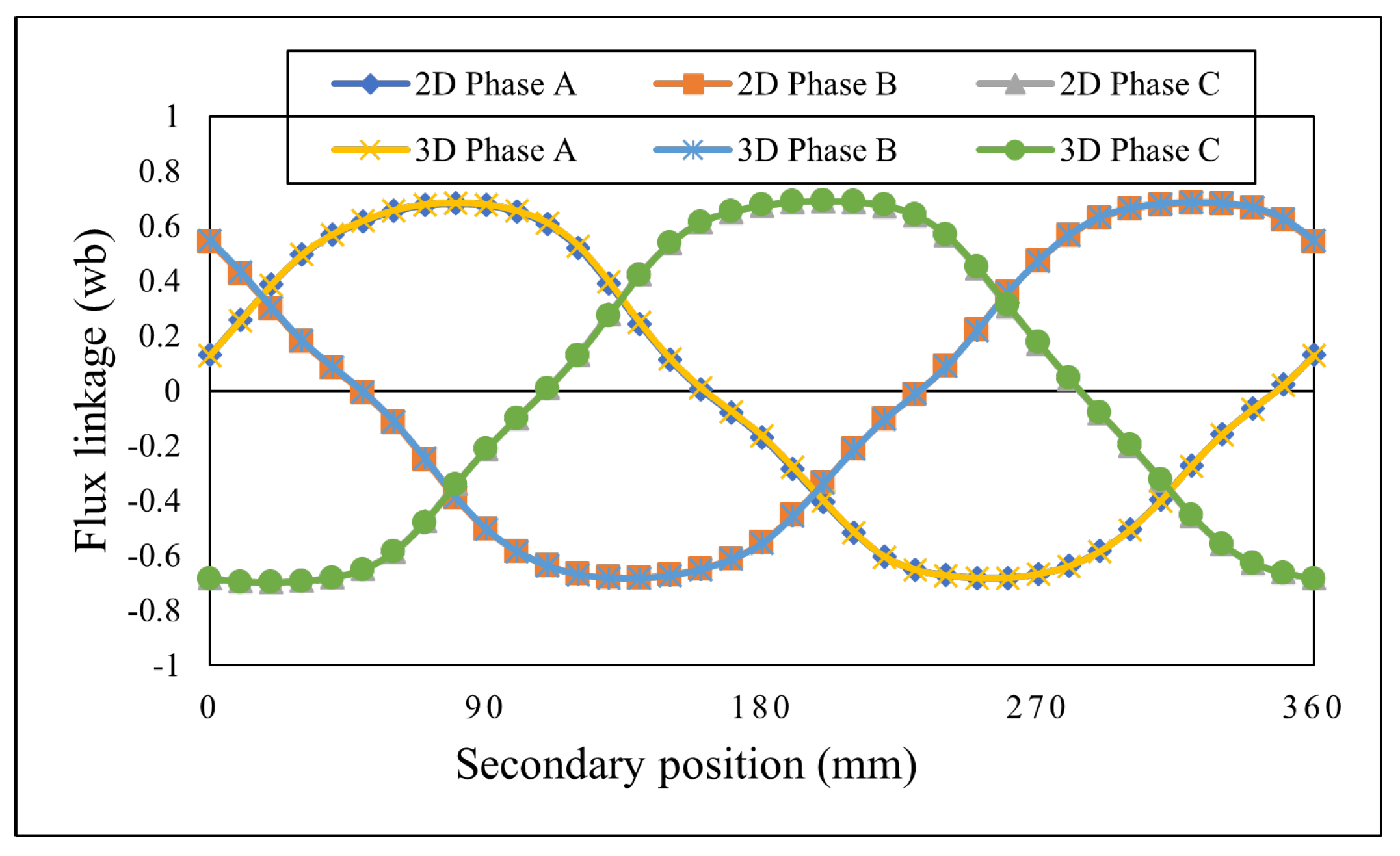
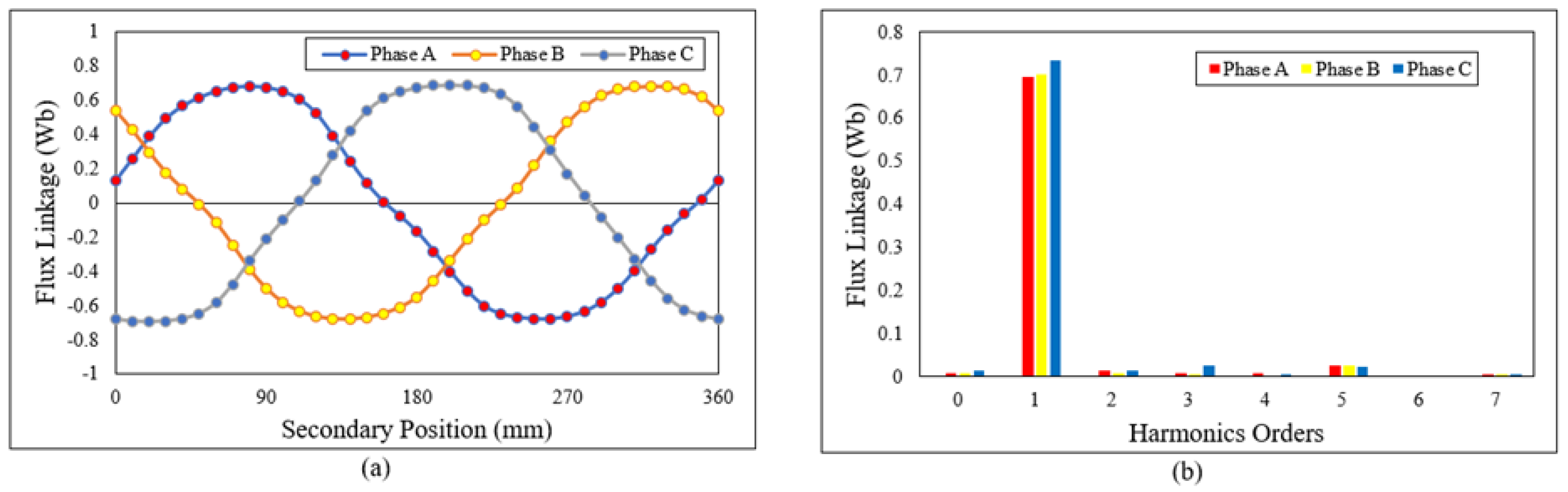
6.2. Flux Linkage and Back EMF of LHEFSM, DSLHEFSM, and DMLHEFSM
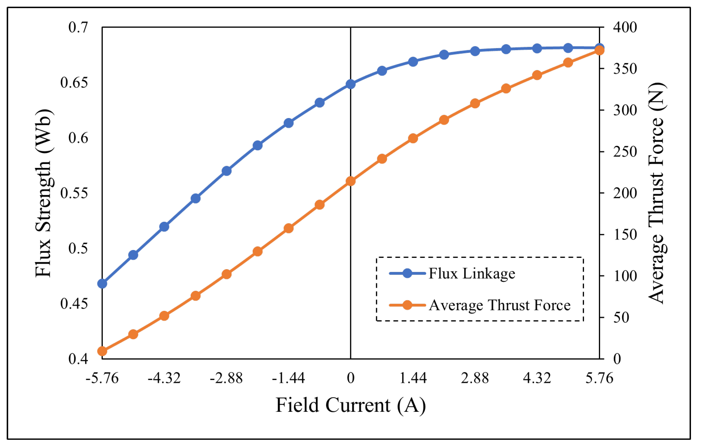
6.3. Flux Regulation
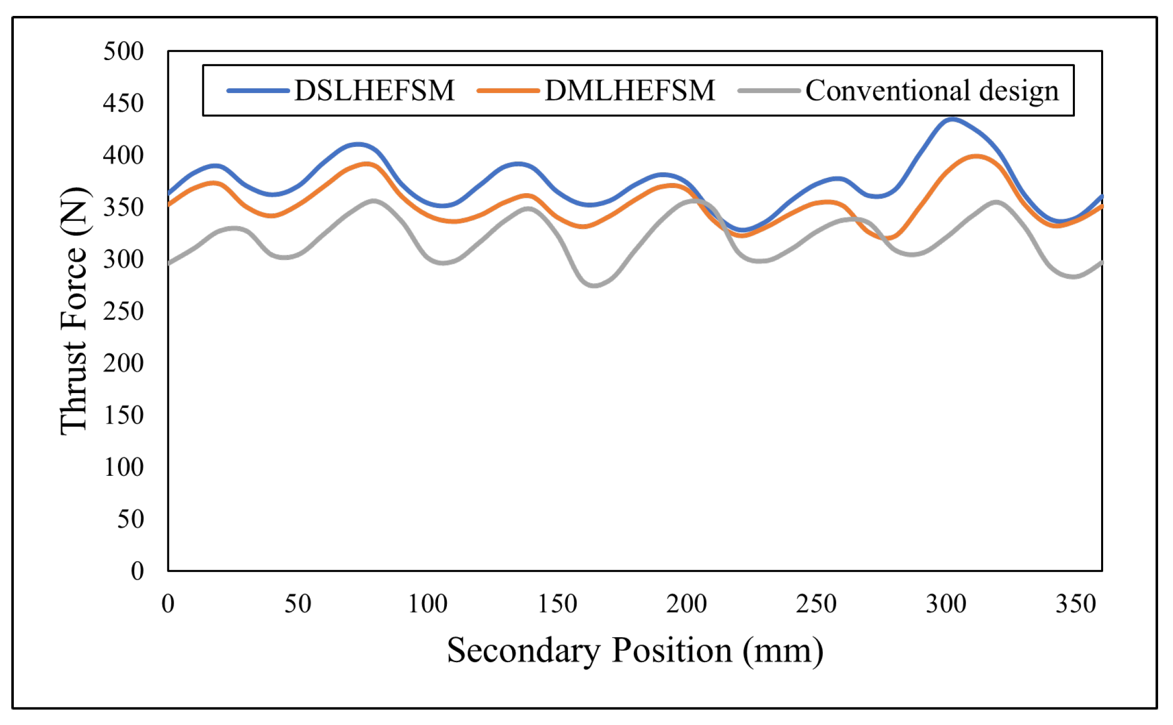
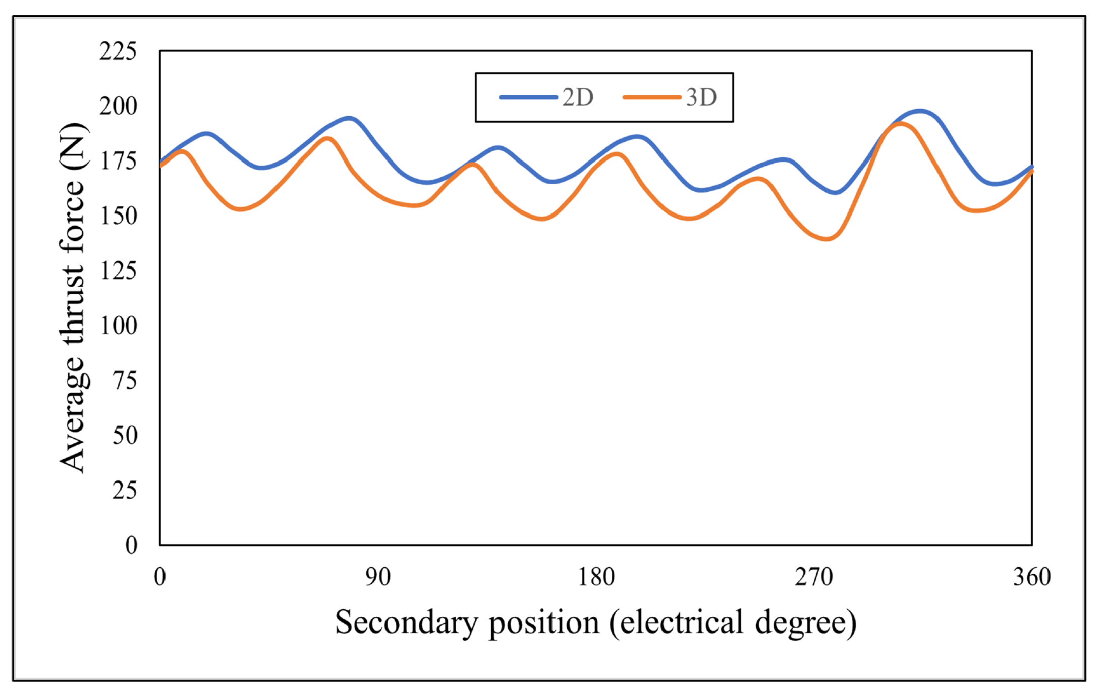
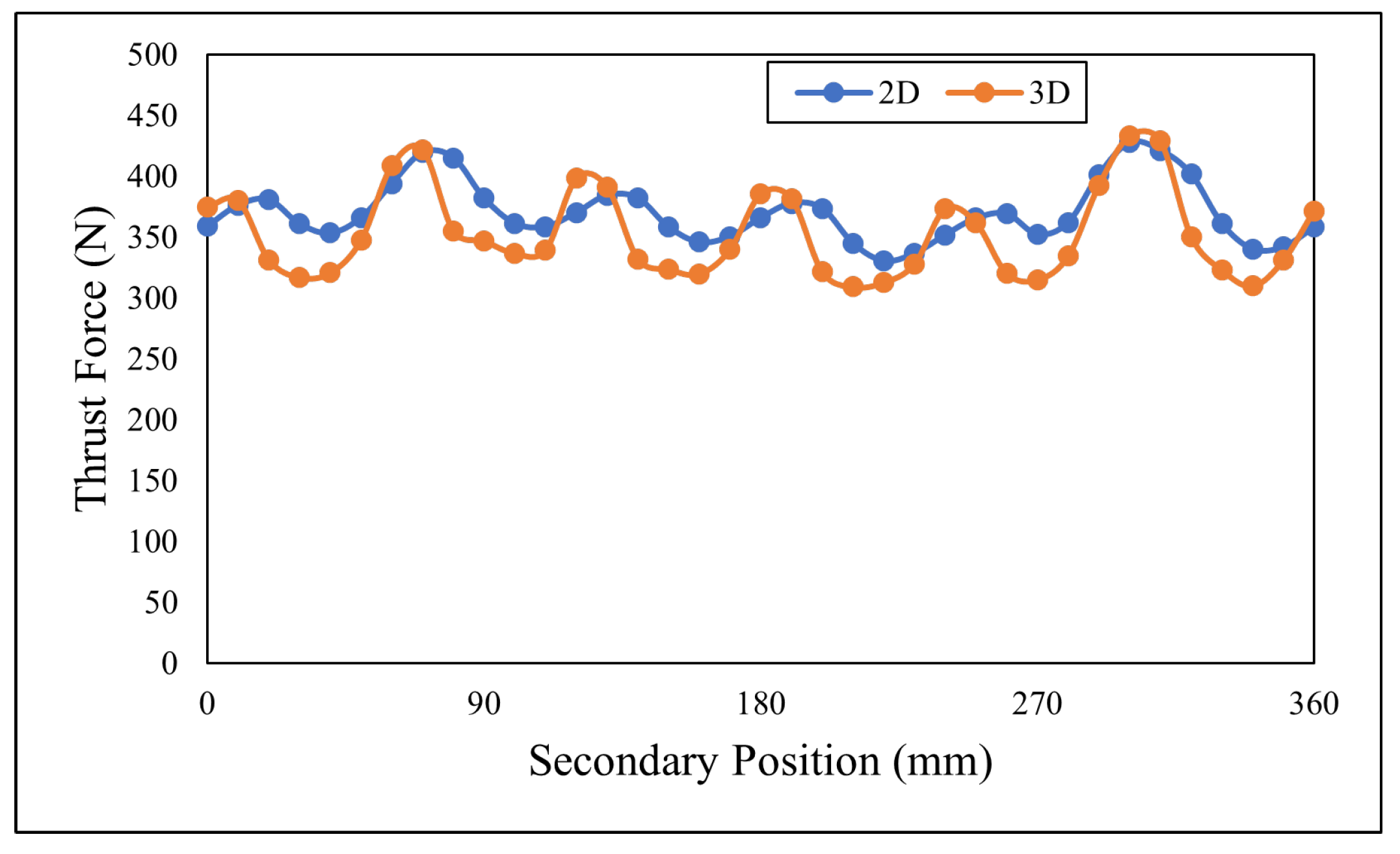
6.4. Thrust Force
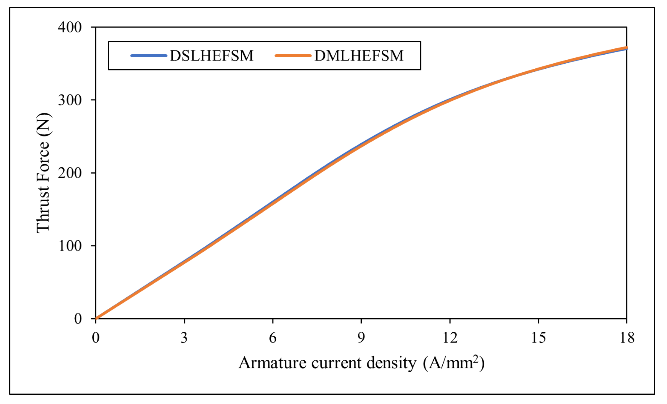
6.5. Variation in Thrust Force as a Function of Current Density
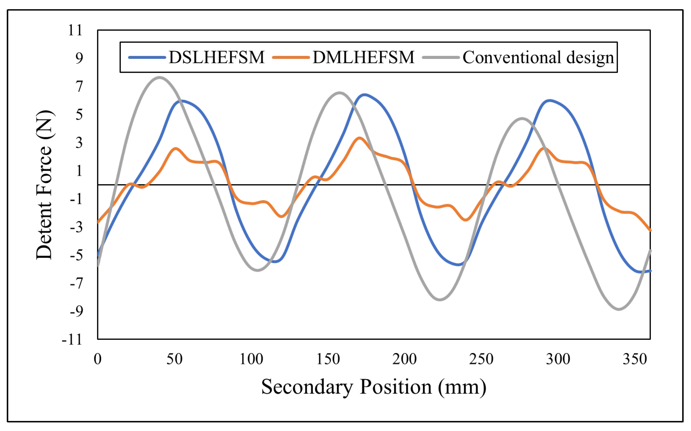
6.6. Detent Force
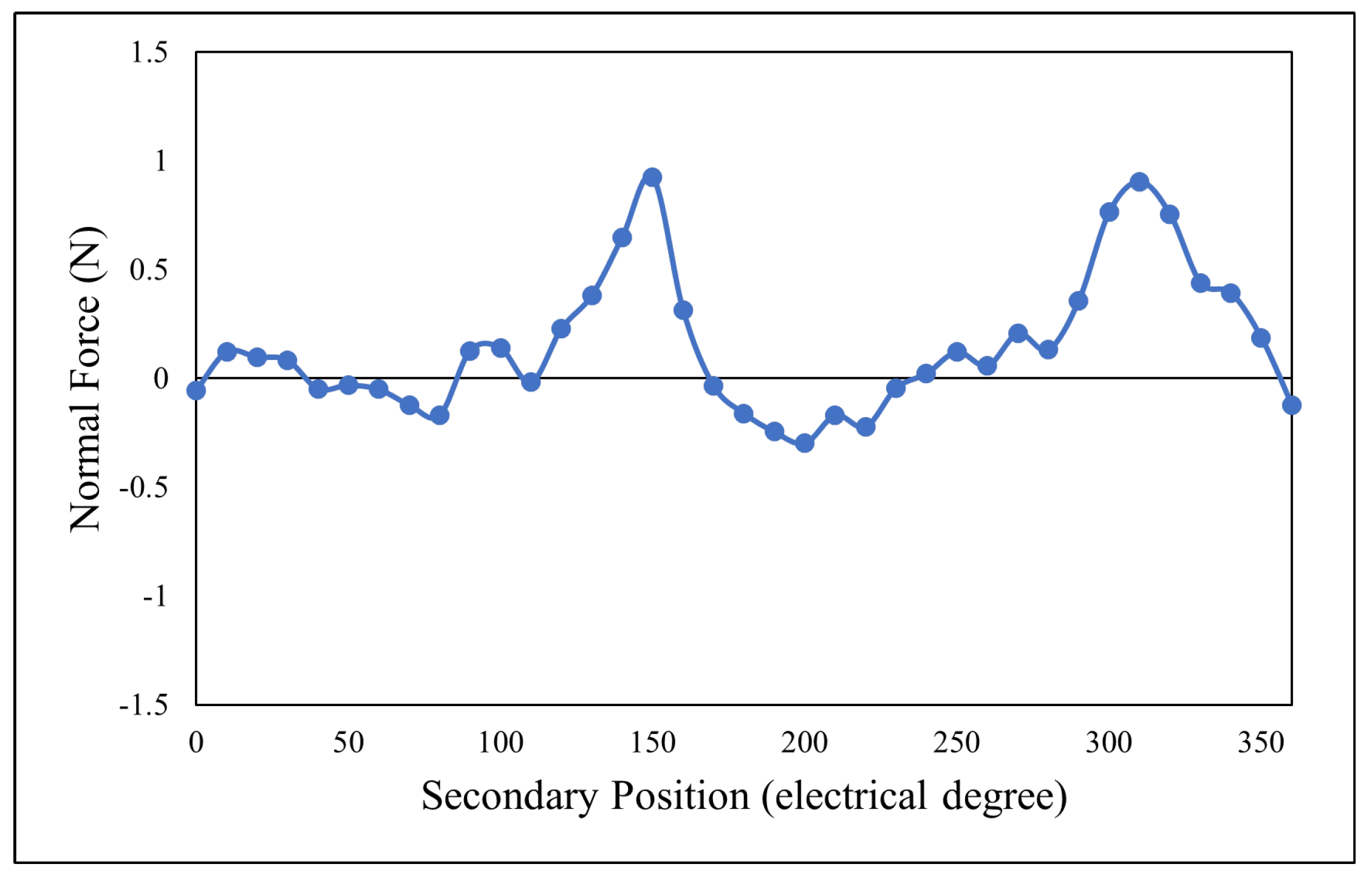
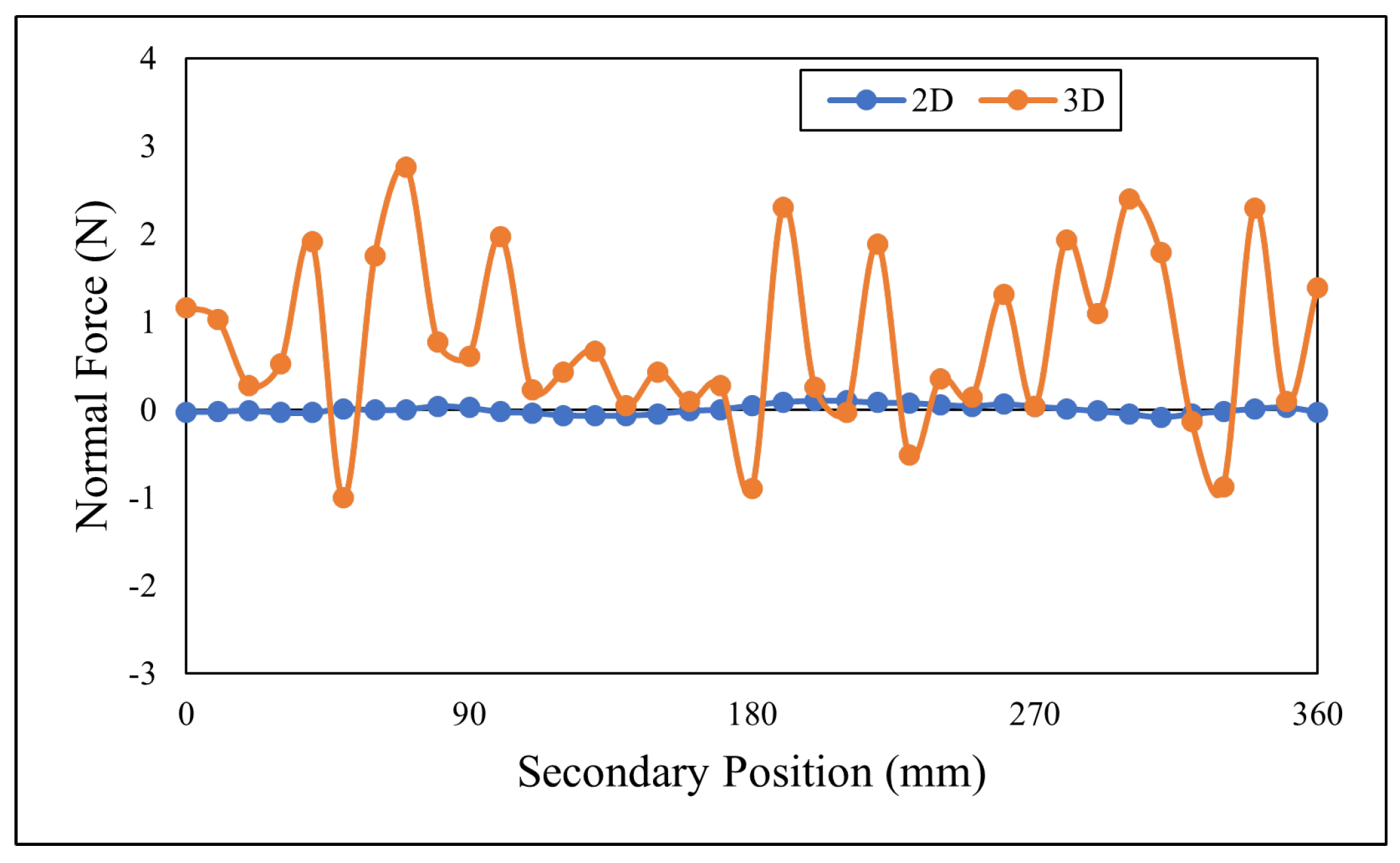
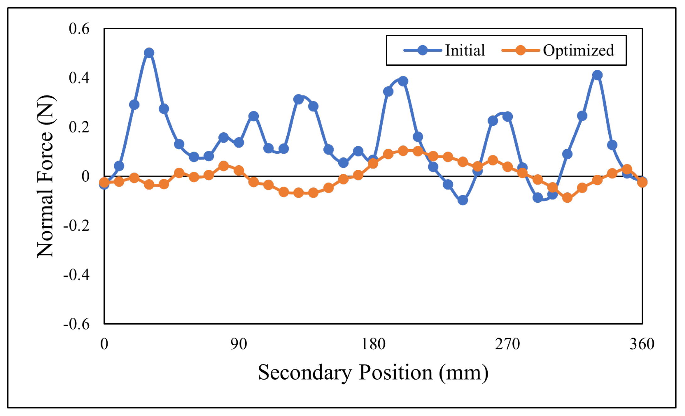
6.7. Normal Force
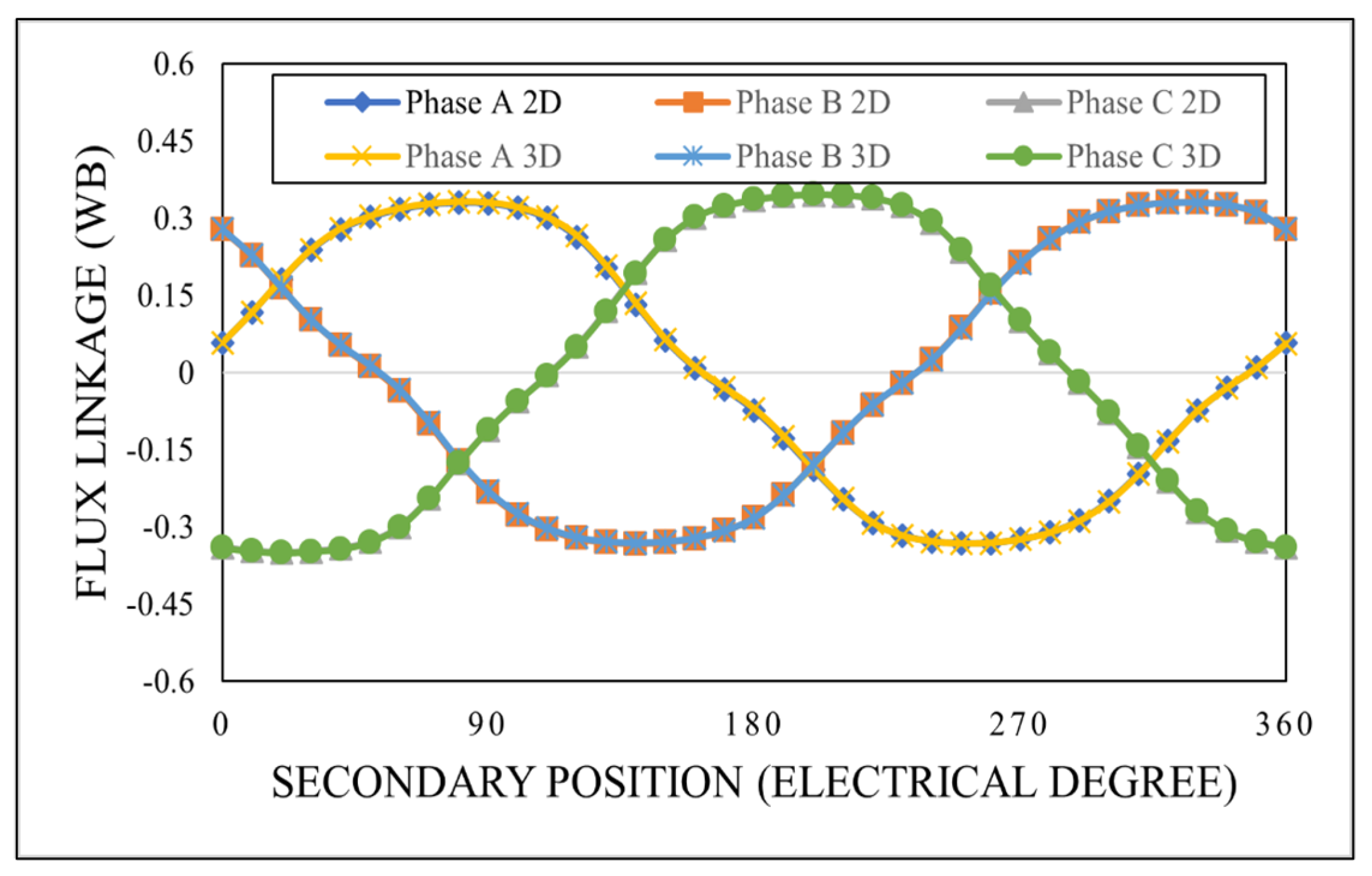
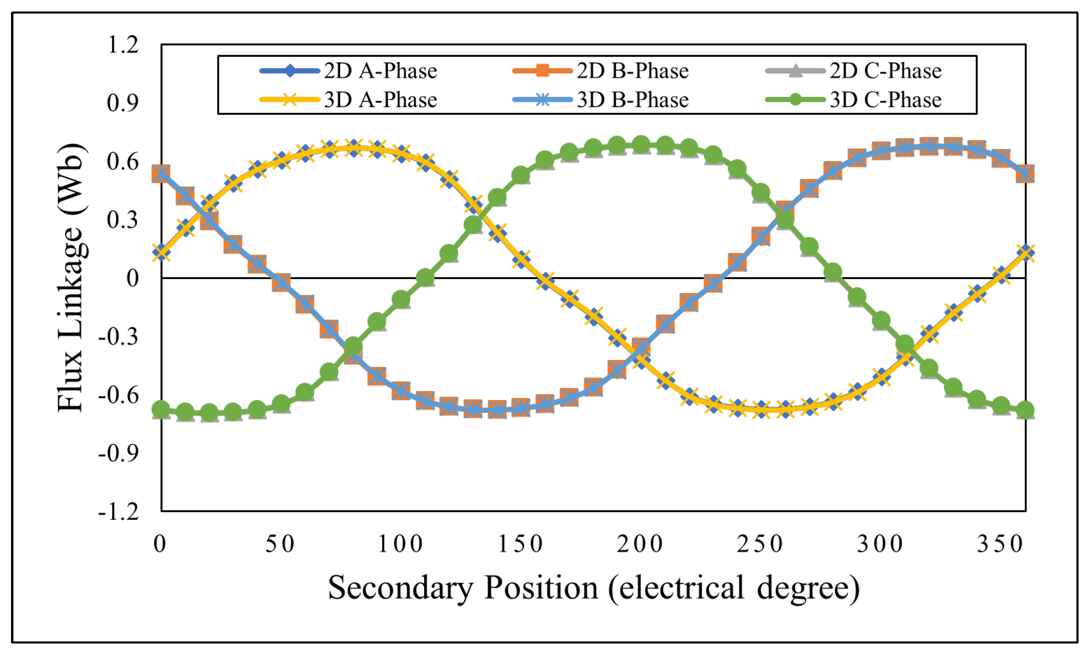
6.8. 3D Analysis
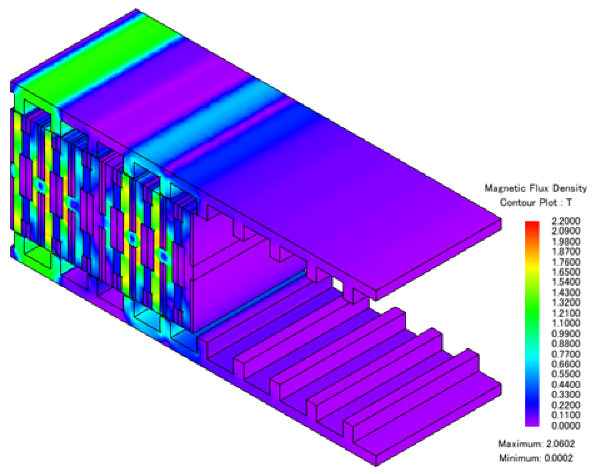
6.9. Magnetic Flux Density
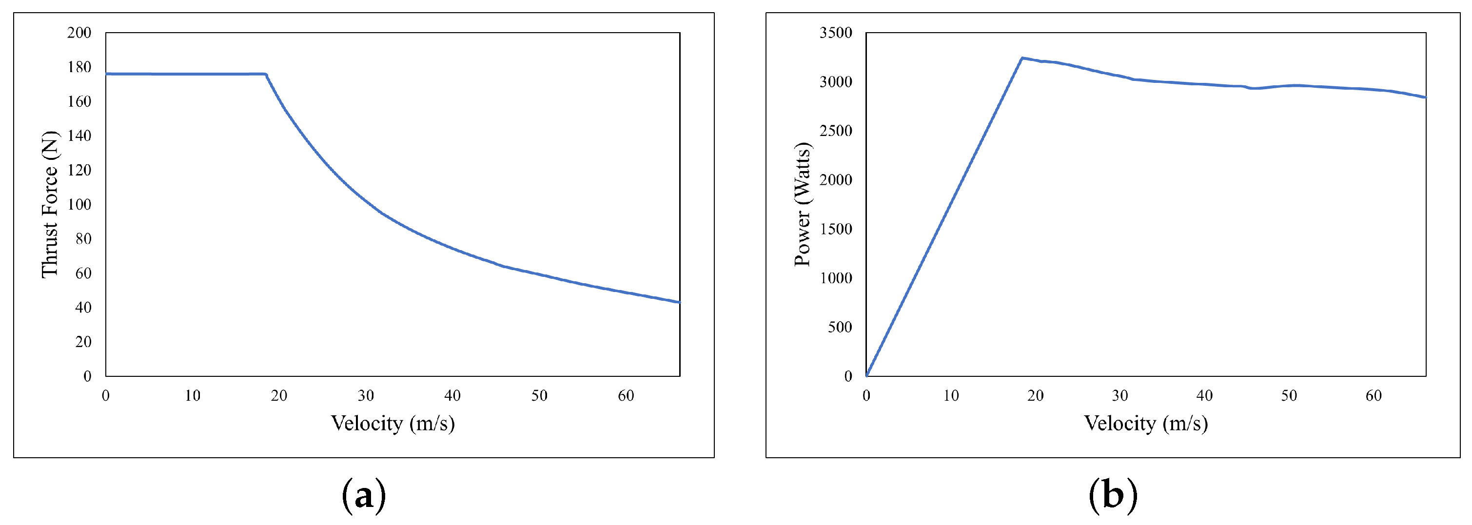
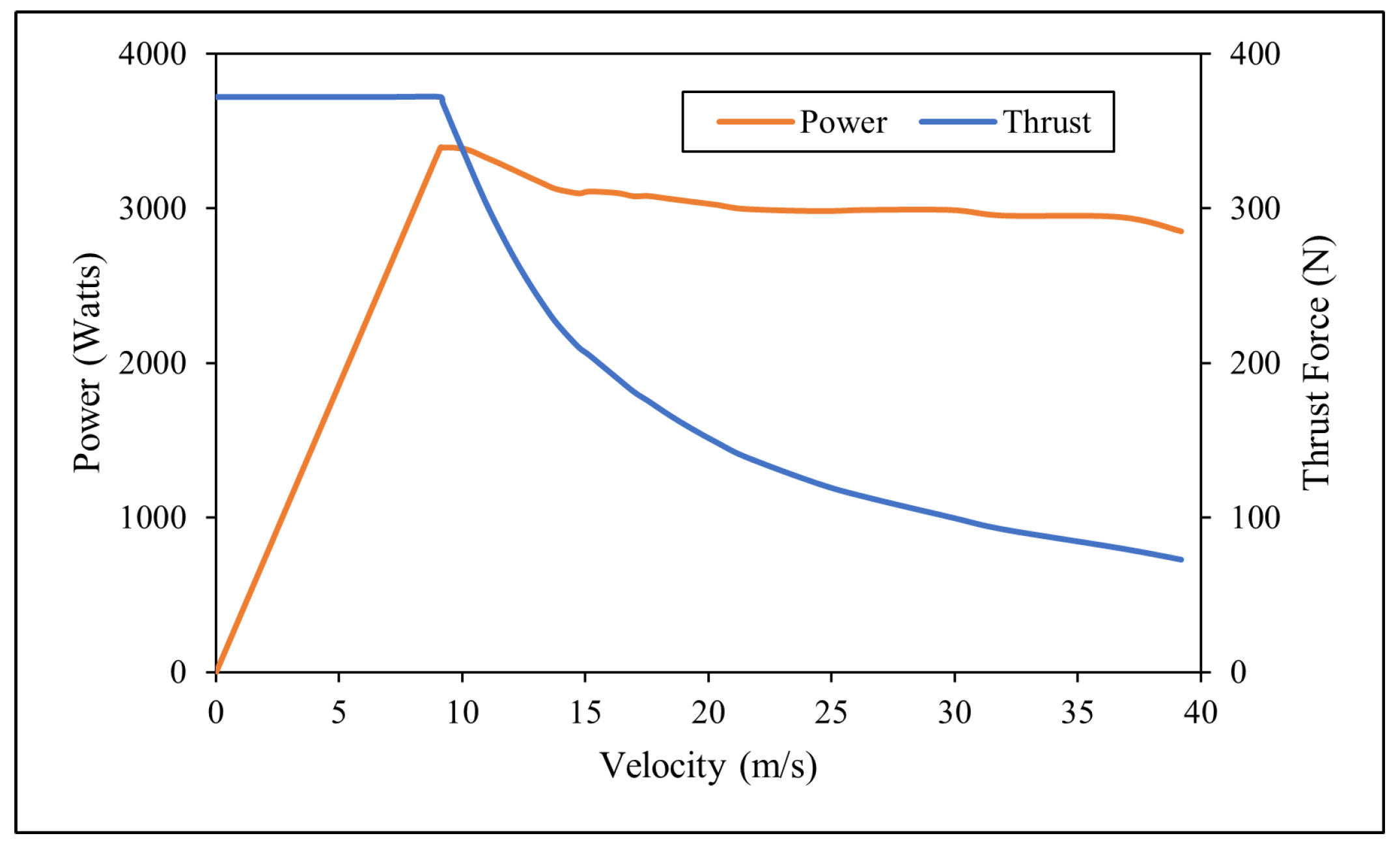
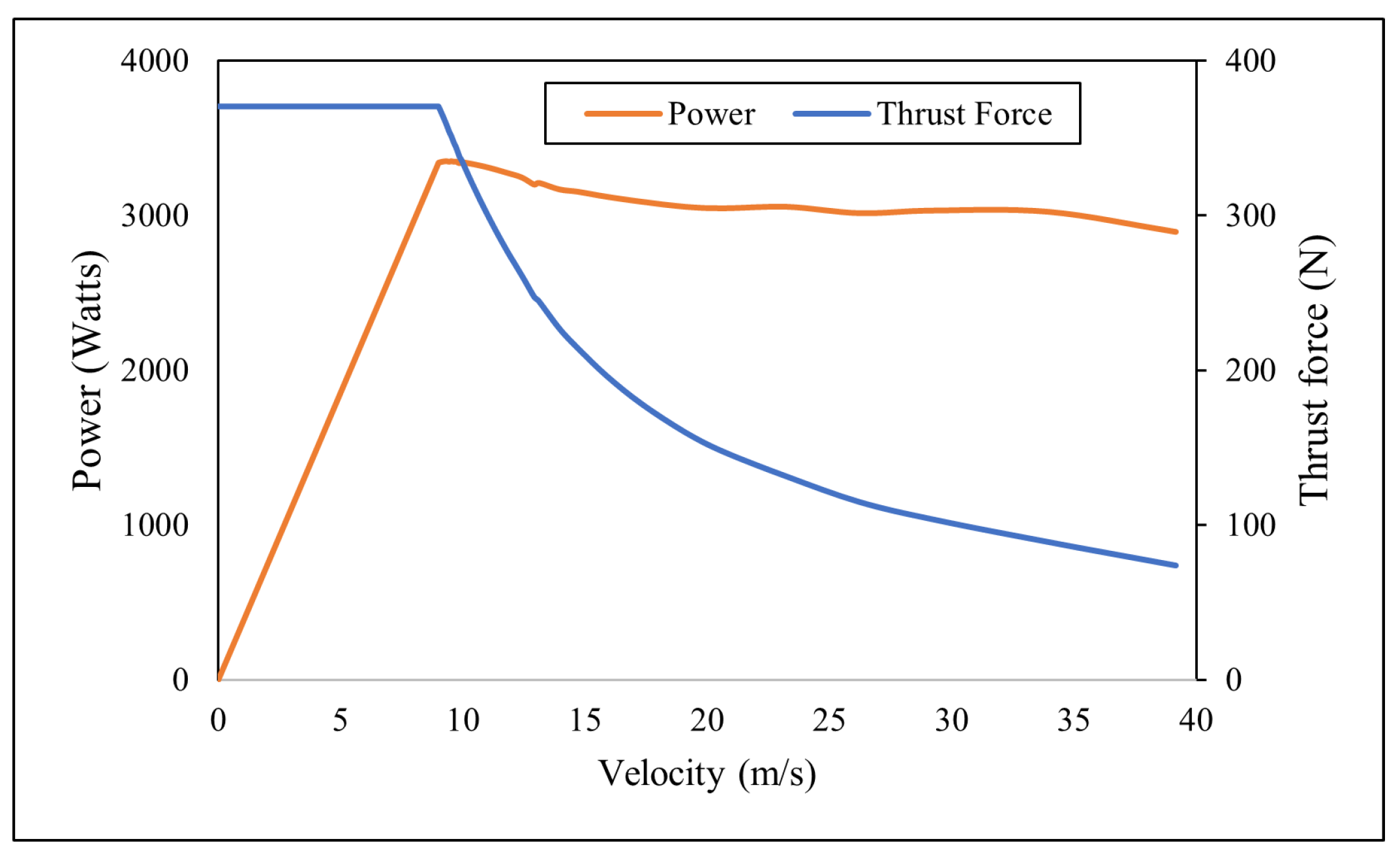
6.10. Force-Speed Characteristics
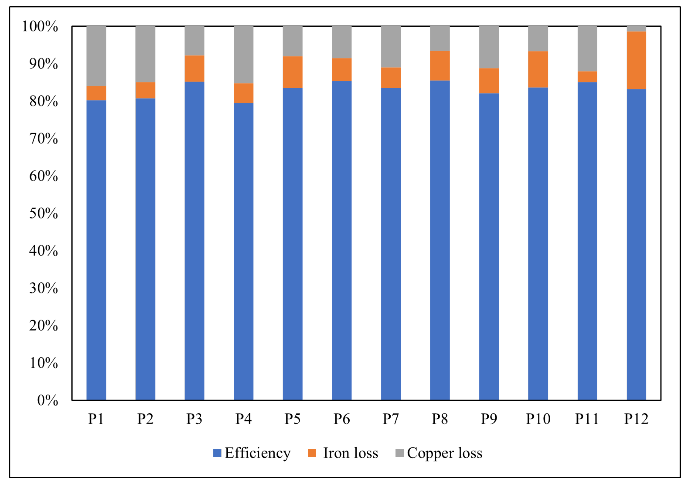
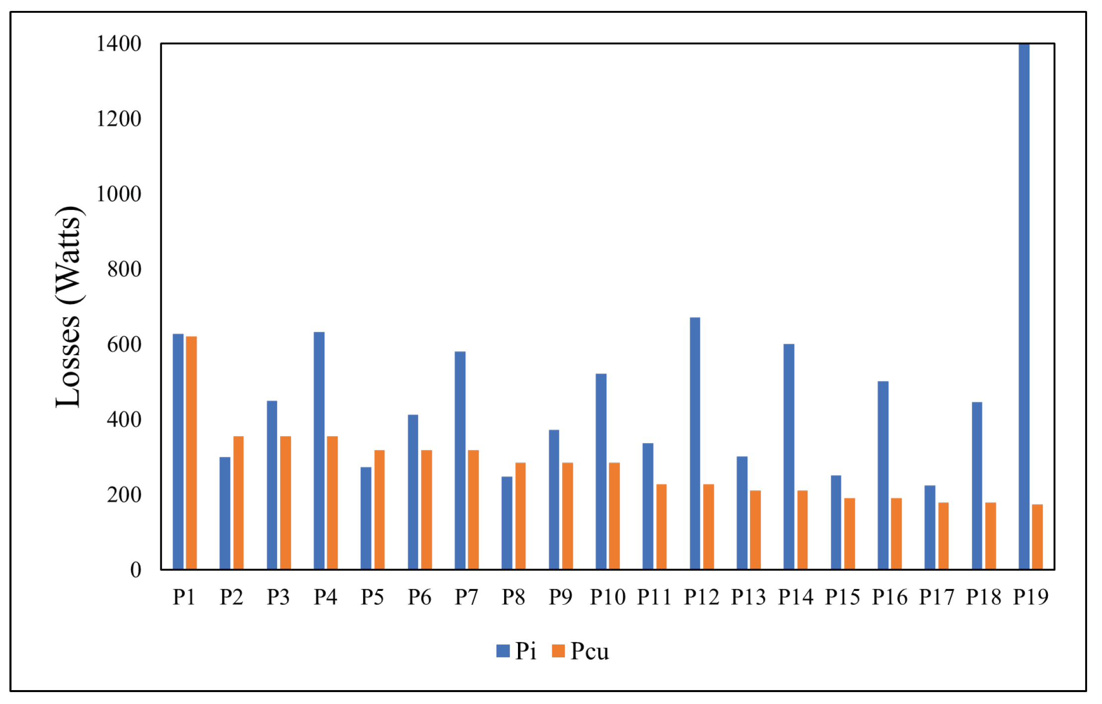
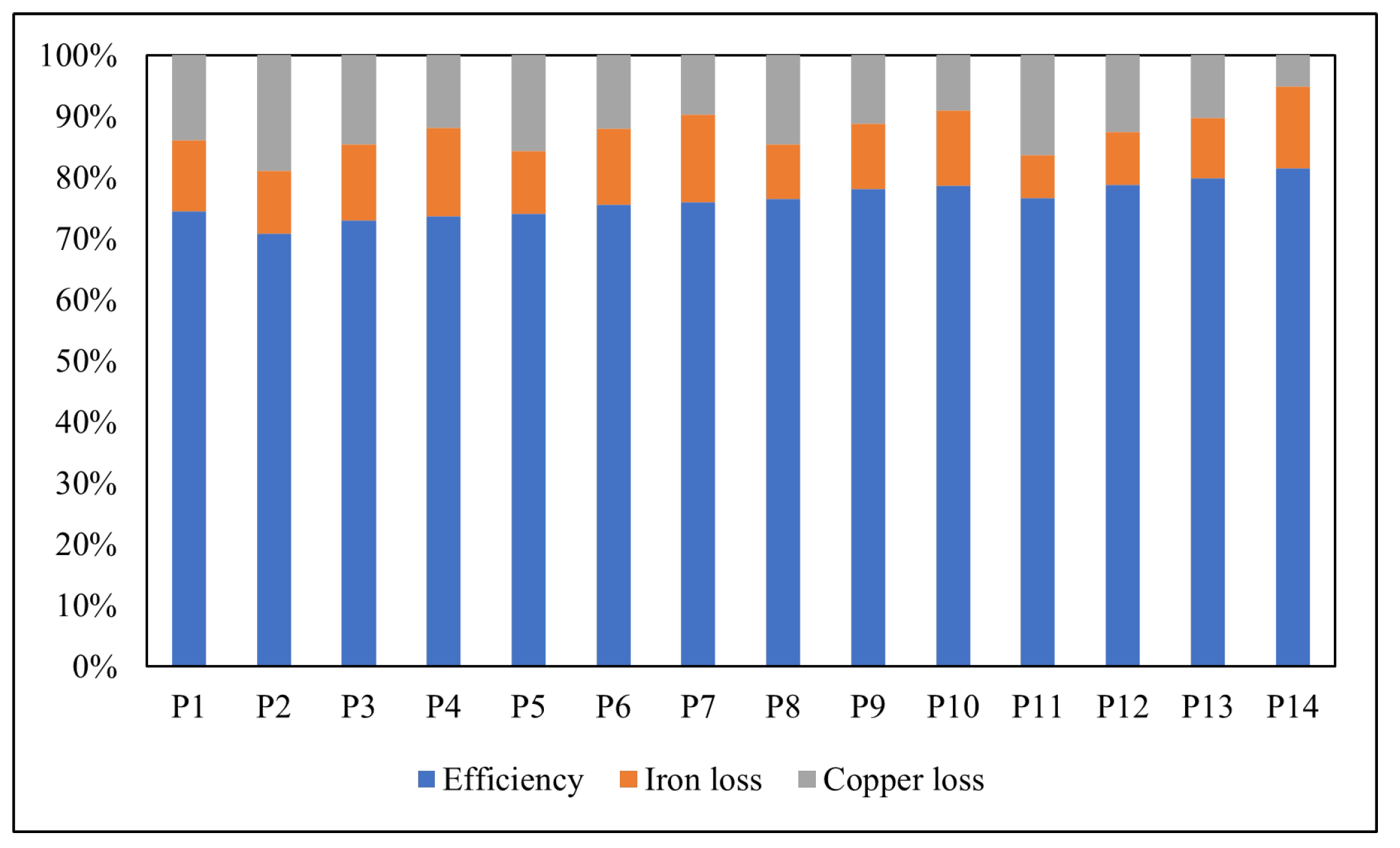
6.11. Efficiency
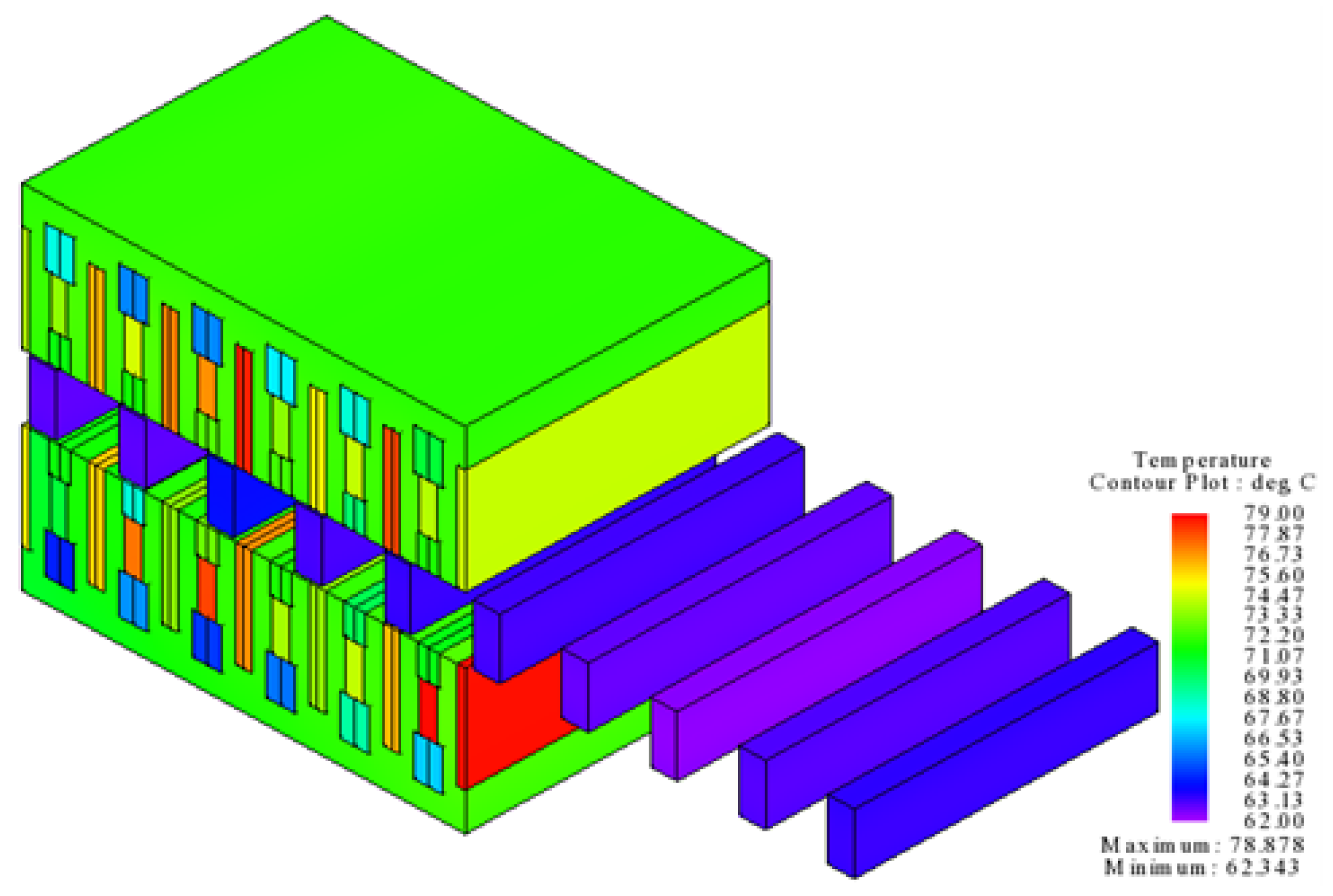
6.12. Thermal Analysis
6.13. Comparison with Conventional Model
7. Conclusions
Author Contributions
Funding
Institutional Review Board Statement
Informed Consent Statement
Data Availability Statement
Acknowledgments
Conflicts of Interest
References
- Magill, M. Laboratory Experiment No. 5: Advanced Induction Machine Topics; Royal Institute of Technology (KTH): Stockholm, Sweden, 2010. [Google Scholar]
- Sadler, G.; Davey, A. Applications of linear induction motors in industry. Proc. IET Inst. Electr. Eng. 1971, 118, 765–776. [Google Scholar] [CrossRef]
- Lee, H.W.; Kim, K.C.; Lee, J. Review of maglev train technologies. IEEE Trans. Magn. 2006, 42, 1917–1925. [Google Scholar]
- Gurol, H. General atomics linear motor applications: Moving towards deployment. Proc. IEEE 2009, 97, 1864–1871. [Google Scholar] [CrossRef]
- Roop, S.S.; Roco, C.E.; Olson, L.E.; Morgan, C.A. Freight Transportation System and Method. U.S. Patent 7,654,203, 2 February 2010. [Google Scholar]
- Houser, M.; Price, C. Ocean Energy System and Method. U.S. Patent 7,786,609, 31 August 2010. [Google Scholar]
- Kotlyar, O. Electrical Linear Motor for Marine Propulsion. U.S. Patent 7,604,520, 20 October 2009. [Google Scholar]
- Yan, L.; Li, W.; Jiao, Z.; Chen, C.Y.; Chen, I.M. Design and modeling of three-phase tubular linear flux-switching permanent magnet motor. In Proceedings of the 2014 IEEE Chinese Guidance, Navigation and Control Conference, Yantai, China, 8–10 August 2014; pp. 2675–2680. [Google Scholar]
- Zhang, B.; Cheng, M.; Cao, R.; Du, Y.; Zhang, G. Analysis of linear flux-switching permanent magnet motor using response surface methodology. IEEE Trans. Magn. 2014, 50, 1–4. [Google Scholar] [CrossRef]
- Cao, R.; Cheng, M.; Mi, C.C.; Hua, W. Influence of leading design parameters on the force performance of a complementary and modular linear flux-switching permanent-magnet motor. IEEE Trans. Ind. Electron. 2013, 61, 2165–2175. [Google Scholar] [CrossRef]
- Abdollahi, S.E.; Vaez-Zadeh, S. Back EMF analysis of a novel linear flux switching motor with segmented secondary. IEEE Trans. Magn. 2013, 50, 1–9. [Google Scholar] [CrossRef]
- Khalid, S.; Khan, F.; Ahmad, Z.; Ullah, B. Design and finite element analysis of modular C-Core stator tubular linear oscillating actuator for miniature compressor. World J. Eng. 2021. [Google Scholar] [CrossRef]
- Zhu, Z.; Chen, X.; Chen, J.; Howe, D.; Dai, J. Novel linear flux-switching permanent magnet machines. In Proceedings of the 2008 International Conference on Electrical Machines and Systems, Wuhan, China, 17–20 October 2008; pp. 2948–2953. [Google Scholar]
- Chung, S.U.; Lee, H.J.; Woo, B.C.; Kim, J.W.; Lee, J.Y.; Moon, S.R.; Hwang, S.M. A feasibility study on a new doubly salient permanent magnet linear synchronous machine. IEEE Trans. Magn. 2010, 46, 1572–1575. [Google Scholar] [CrossRef]
- Ullah, B.; Khan, F.; Milyani, A.H.; Ahmad, N.; Cheema, K.M. Design and analysis of dual-stator hybrid excited linear flux switching machine for long-stroke applications. IET Electr. Power Appl. 2021, 15, 1678–1691. [Google Scholar] [CrossRef]
- Ullah, B.; Khan, F.; Qasim, M.; Jan, H.U.; Khan, B.; Khalid, S. Design and Electromagnetic Performance Analysis of Linear Hybrid Excited Flux Switching Machine for Long Stroke Applications. In Proceedings of the 2021 IEEE International Power and Renewable Energy Conference (IPRECON), Kollam, India, 24–26 September 2021; pp. 1–6. [Google Scholar]
- Ullah, B.; Khan, F.; Qasim, M.; Jan, H.U.; Khan, B.; Khalid, S. Design and Analysis of Consequent Pole Dual Stator Hybrid Excited Linear Flux Switching Machine for Rail Transit System. In Proceedings of the IEEE 2021 International Conference on Emerging Power Technologies (ICEPT), Topi, Pakistan, 10–11 April 2021; pp. 1–6. [Google Scholar]
- Qasim, M.; Khan, F.; Jan, H.U.; Ullah, B.; Ejaz, B.; Hussain, S. Novel Partitioned Primary Linear Hybrid Excited Flux Switching Machine with Segmented Secondary. In Proceedings of the IEEE 2021 International Conference on Emerging Power Technologies (ICEPT), Topi, Pakistan, 10–11 April 2021; pp. 1–6. [Google Scholar]
- Chen, J.; Zhu, Z. Winding configurations and optimal stator and rotor pole combination of flux-switching PM brushless AC machines. IEEE Trans. Energy Convers. 2009, 25, 293–302. [Google Scholar] [CrossRef]
- Liu, J.; Chen, Y.; Lu, Q.; Ye, Y.; Huang, X. Optimization and comparison of C-core and E-core linear switched-flux PM machines with odd primary poles. In Proceedings of the IEEE 2015 18th International Conference on Electrical Machines and Systems (ICEMS), Pattaya, Thailand, 25–28 October 2015; pp. 254–259. [Google Scholar]
- Wang, C.; Shen, J.; Wang, L.; Wang, K. A novel permanent magnet flux-switching linear motor. In Proceedings of the 2008 4th IET Conference on Power Electronics, Machines and Drives, York, UK, 2–4 April 2008; pp. 116–119. [Google Scholar]
- Min, W.; Chen, J.; Zhu, Z.; Zhu, Y.; Duan, G. Optimization of linear flux switching permanent magnet motor. In Proceedings of the 2010 IEEE Vehicle Power and Propulsion Conference, Lille, France, 1–3 September 2010; pp. 1–6. [Google Scholar]
- Zheng, P.; Sui, Y.; Tong, C.; Bai, J.; Yu, B.; Lin, F. A novel single-phase flux-switching permanent magnet linear generator used for free-piston Stirling engine. J. Appl. Phys. 2014, 115, 17E711. [Google Scholar] [CrossRef]
- Hussain, S.; Khan, F.; Ullah, W.; Ullah, B.; Khan, B. Development of a Low-Cost Modular Structure Fault Tolerant Field Excited Flux Switching Linear Machine for Urban Rail Transit. IEEE Access 2021, 9, 165854–165864. [Google Scholar] [CrossRef]
- Zhu, Z. Switched flux permanent magnet machines—Innovation continues. In Proceedings of the IEEE 2011 International Conference on Electrical Machines and Systems, Beijing, China, 20–23 August 2011; pp. 1–10. [Google Scholar]
- Ji, J.; Zhao, J.; Zhao, W.; Fang, Z.; Liu, G.; Du, Y. New high force density tubular permanent-magnet motor. IEEE Trans. Appl. Supercond. 2013, 24, 1–5. [Google Scholar] [CrossRef]
- Gandhi, A.; Parsa, L. Hybrid flux-switching linear machine with fault-tolerant capability. In Proceedings of the 2015 IEEE International Electric Machines & Drives Conference (IEMDC), Coeur d’Alene, ID, USA, 11–13 May 2015; pp. 715–720. [Google Scholar]
- Issac, S.; Poorani, S. A review on design of single sided linear induction motor to improve performance. Int. J. Pure Appl. Math. 2017, 116, 109–125. [Google Scholar]
- Hwang, C.C.; Li, P.L.; Liu, C.T. Design and analysis of a novel hybrid excited linear flux switching permanent magnet motor. IEEE Trans. Magn. 2012, 48, 2969–2972. [Google Scholar] [CrossRef]
- Liu, C.T.; Hwang, C.C.; Li, P.L.; Hung, S.S.; Wendling, P. Design optimization of a double-sided hybrid excited linear flux switching PM motor with low force ripple. IEEE Trans. Magn. 2014, 50, 1–4. [Google Scholar] [CrossRef]
- Islam, M.S.; Islam, R.; Sebastian, T. Noise and vibration characteristics of permanent-magnet synchronous motors using electromagnetic and structural analyses. IEEE Trans. Ind. Appl. 2014, 50, 3214–3222. [Google Scholar] [CrossRef]
- Qi, G.; Chen, J.; Zhu, Z.; Howe, D.; Zhou, L.; Gu, C. Influence of skew and cross-coupling on flux-weakening performance of permanent-magnet brushless AC machines. IEEE Trans. Magn. 2009, 45, 2110–2117. [Google Scholar] [CrossRef] [Green Version]


| Symbol | Parameter (Unit) | LHEFSM | DSLHEFSM | DMLHEFSM |
|---|---|---|---|---|
| Mover pole pitch (mm) | 21.832 | 21.832 | 21.832 | |
| Stator pole pitch (mm) | 26.19 | 26.19 | 26.19 | |
| Mover height (mm) | 44.3 | 82 | 88.4 | |
| AC slot height (mm) | 28.95 | 32.60 | 32.60 | |
| DC upper slot height (mm) | 10.42 | 12.55 | 12.55 | |
| DC lower slot height (mm) | 9.264 | 9.264 | 9.264 | |
| Magnet height (mm) | 15.169 | 15.169 | 15.169 | |
| Stator teeth width (mm) | 10.47 | 7.85 | 7.85 | |
| Mover yoke height (mm) | 7 | 8 | 7.23 | |
| g | Air gap | 0.8 | 0.8 | 0.8 |
| L | Stack length (mm) | 90 | 90 | 90 |
| Mover length (mm) | 131 | 131 | 131 | |
| Stator height (mm) | 11.58 | 12.50 | 18.55 | |
| v | Rated speed m/s | 4 | 4 | 4 |
| Upper DC coil turns | 45 | 45 | 45 | |
| Lower DC coil turns | 24 | 24 | 24 | |
| AC coil turns | 136 | 136 | 136 | |
| Whole machine height (mm) | 54.3 | 108.6 | 108.6 |
| Sq. No. | Coefficients | Initial Value | Ranges |
|---|---|---|---|
| 1 | 0.2279 | [0.18–0.28] | |
| 2 | 0.0897 | [0.11–0.29] | |
| 3 | 0.3366 | [0.21–0.45] | |
| 4 | 0.4987 | [0.26–0.40] | |
| 5 | 0.5 | [0.25–0.65] | |
| 6 | 0.5 | [0.30–0.65] |
| Key Performance Indicator | Initial Values | Optimized Values |
|---|---|---|
| 0.368 | 0.695 | |
| 8.35 | 2.76 | |
| 150.7 | 175.93 | |
| 12.9 | 20.69 |
| Sq. No. | Coefficients | Initial Value | Ranges |
|---|---|---|---|
| 1 | 0.25 | [0.15–0.30] | |
| 2 | 0.07 | [0.07–0.28] | |
| 3 | 0.3 | [0.128–0.681] | |
| 4 | 0.5 | [0.061–0.48] |
| Key Performance Indicator | Initial Design | Optimized Design |
|---|---|---|
| 1.36 | 1.37 | |
| 8.04 | 12.3 | |
| 354 | 372 | |
| 0.90 | 1.22 | |
| 25.2 | 28.2 | |
| (%) | 3.44 | 3.94 |
| 405.87 | 426.5 |
| Sq. No. | Coefficients | Initial Value | Ranges |
|---|---|---|---|
| 1 | 0.25 | [0.185–0.30] | |
| 2 | 0.07 | [0.07–0.10] | |
| 3 | 0.31 | [0.10–0.65] | |
| 4 | 0.75 | [0.32–1.0] |
| Key Performance Indicator (Unit) | Initial Design | Optimized Design |
|---|---|---|
| 1.33 | 1.37 | |
| 6.89 | 6.54 | |
| 353 | 370 | |
| 0.59 | 0.18 | |
| 21.7 | 26.1 | |
| 2.16 | 2.19 |
Publisher’s Note: MDPI stays neutral with regard to jurisdictional claims in published maps and institutional affiliations. |
© 2022 by the authors. Licensee MDPI, Basel, Switzerland. This article is an open access article distributed under the terms and conditions of the Creative Commons Attribution (CC BY) license (https://creativecommons.org/licenses/by/4.0/).
Share and Cite
Qasim, M.; Khan, F.; Ullah, B.; Jan, H.U.; Alkhammash, H.I. Analysis of Linear Hybrid Excited Flux Switching Machines with Low-Cost Ferrite Magnets. Energies 2022, 15, 1346. https://doi.org/10.3390/en15041346
Qasim M, Khan F, Ullah B, Jan HU, Alkhammash HI. Analysis of Linear Hybrid Excited Flux Switching Machines with Low-Cost Ferrite Magnets. Energies. 2022; 15(4):1346. https://doi.org/10.3390/en15041346
Chicago/Turabian StyleQasim, Muhammad, Faisal Khan, Basharat Ullah, Himayat Ullah Jan, and Hend I. Alkhammash. 2022. "Analysis of Linear Hybrid Excited Flux Switching Machines with Low-Cost Ferrite Magnets" Energies 15, no. 4: 1346. https://doi.org/10.3390/en15041346
APA StyleQasim, M., Khan, F., Ullah, B., Jan, H. U., & Alkhammash, H. I. (2022). Analysis of Linear Hybrid Excited Flux Switching Machines with Low-Cost Ferrite Magnets. Energies, 15(4), 1346. https://doi.org/10.3390/en15041346