Article

A Fuzzy Logic-Based Emulated Inertia Control to a Supercapacitor System to Improve Inertia in a Low Inertia Grid with Renewables

by
Ratnam Kamala Sarojini
1,
Kaliannan Palanisamy
2,* and
Enrico De Tuglie
3
1
Capgemini Technology Services India Limited, Bengaluru 560048, India
2
School of Electrical Engineering, Vellore Institute of Technology, Vellore 632014, India
3
Department of Electrical and Information Engineering, Polytechnic University of Bari, 70126 Bari, Italy
*
Author to whom correspondence should be addressed.
Energies 2022, 15(4), 1333; https://doi.org/10.3390/en15041333
Submission received: 16 December 2021 / Revised: 17 January 2022 / Accepted: 8 February 2022 / Published: 12 February 2022

Abstract

:
The contribution of power generation from converter-dominated renewable energy sources (RES) has increased enormously. Consequently, the system inertia is decreasing, and it impacts the frequency of the system. With large-scale integration of power electronic inverter-based power generation from RES, inertia from energy storage devices would be unavoidable in future power grids. In this paper, the inertia emulator is formed with a supercapacitor (IE–SC) to improve inertia in a low inertia grid. To emulate the inertia in a low inertia grid, this paper proposes a fuzzy logic controller-based emulated inertia controller (FL-EIC) for an inverter attached to IE–SC. The proposed fuzzy logic controller estimates the inertial power required based on the frequency deviation and rate of change of frequency (ROCOF). The output of the fuzzy controller adds to the conventional emulated inertia control (EIC) technique to alter the load angle for the power electronic inverter of IE–SC. Specifically, the proposed FL-EIC achieves inertia emulation by proportionally linking the time derivative of the grid frequency and frequency deviation to active power references of IE–SC. A comparison of the conventional EIC and FL-EIC is carried out to prove the effectiveness of the proposed FL-EIC. Furthermore, real-time simulations with the help of the OPAL-RT real-time simulator (OP 5700) are presented to validate the advantage of the FL-EIC.

1. Introduction

To minimize emissions and generate power from renewable energy, several countries’ initiatives on the environment are directed at reaching wide-scale incorporation of non-synchronous generation into the grid [1]. RES such as solar and wind are connected to the grid through a power electronic converter since power generation from renewable energy sources (RES) is not compatible with the grid. As a result, RESs dependent on power electronic converters are a key component of the current power system. However, more penetration of RES in the power system influences its stability since power electronic converter-based RES decouples the sources from loads [1]. As a result, grid operators face difficulty in preserving frequency stability due to a decrease in inertia with the advent of power electronic converter-based RES.
Frequency control strategies must operate, so that equilibrium between generation and demand is met to preserve frequency stability in the grid [2]. The frequency response of the power system can be classified into various time frames:
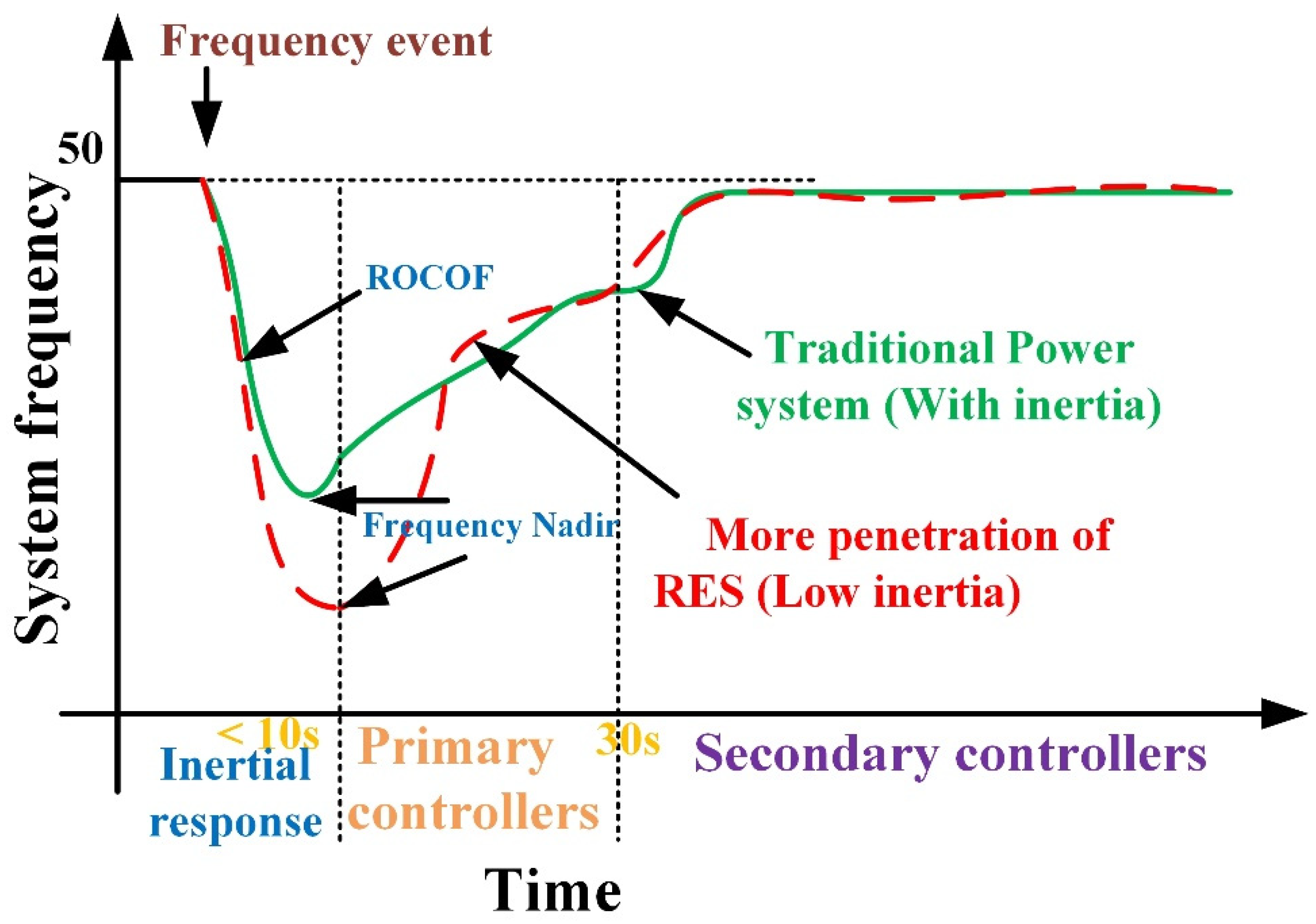
  • Initially, an underlying behavior called inertial frequency response derives energy from the spinning masses to oppose the frequency deviation from nominal frequency.
  • In the next step, governor systems are triggered to hold the frequency variance at an appropriate level (primary control).
  • Finally, a secondary control system is carried out to restore the frequency to its nominal value.
Figure 1 illustrates the various time frames for frequency control of the power system. It is clearly shown that the frequency dip is less when the power generation is only from synchronous generators. It is high if the penetration of RES is more in the power system.
In the contingency event, the frequency nadir (the lowest point of frequency) and rate of change of frequency (ROCOF) are directly correlated with the inertia of the system. Higher ROCOF and frequency deviations under frequency events can cause the protective relay to operate at the generating stations and further cascade outages. Hence, it is crucial to increase the inertia of the power grid to prevent unnecessary ROCOF and reduce frequency variations with a high share of RES in the power [3]. A previous report on future low inertia power systems [4] listed synchronous condensers, DC-bus capacitors, batteries, SC and emulated inertia control techniques (EIC) as sources for improving inertia. Demand-side management can be used to support the grid frequency. An easy alternative to these inertia improvement methods is to add synchronous condensers to provide inertia. However, it undoubtedly leads to more fixed and operating costs [5]. Non-synchronous generation such as PV cannot offer frequency response unless an extra supplementary storage device is attached with a proper control technique. Several EIC techniques have been proposed to manage the inertia of the power grid by emulating a synchronous generator [6,7]. In [6], the EIC technique was proposed to emulate the inertial features for a power electronic inverter in a stand-alone microgrid. EIC can offer the inertial response by supplying/absorbing power from storage devices [7]. The EIC-based power electronic inverter can mimic the inertial characteristics of the synchronous generator.
Some modifications in EIC techniques have been proposed in the literature. Proportional, integral and derivative control combinations have been implemented in the EIC technique [8,9]. In [8], the EIC is emulated according to induction machine principles and proportional-integral controllers. In [9], the static synchronous generator model is presented, the power required in inertial response is derived from DC-bus capacitors. Some researchers [9,10] have adopted the EIC technique to release stored energy in the DC bus to participate in the inertial response. In [11], the inertia is emulated by using HVDC links with an EIC technique based on the swing equation. However, the energy in DC-bus capacitors is less, and cannot support large power imbalances. In [12], de-loading control is applied to offer inertia. Minimum reserve power is maintained for PV systems by using a machine-learning algorithm to support frequency during power imbalances [13]. However, the operating point has to be shifted from maximum power point to a sub-optimal power point, and power from PV has to be sacrificed to preserve the frequency stability. The capacitors available in the DC bus are designed to perform voltage smoothing. The applications of various energy storage devices’ SC, battery and flywheel are supposed to offer inertia to the grid to preserve frequency stability. In [13,14], the battery is used to supply/absorb the power in the inertial response of an islanded microgrid. In [15], the derivative control technique is implemented in the EIC technique to extract inertial response from the energy storage device. The combination of battery and SC is attached to the RES system to offer inertia as an ancillary service for a single-phase rooftop PV system [16]. In [17], the hybrid energy storage (battery + SC) is used to provide the inertial response in a three-phase system. However, ideal DC voltage storage is used to implement the power generation from RES. In [18,19] mechanical energy storage systems such as flywheels are suggested to enhance system inertia. In [20,21,22], the authors used the battery to offer inertia to the grid under imbalances. In [20], the battery is used to supply/absorb the power in an inertial response with an inertia controller to support grid frequency. The battery used to handle the inertial response in DC microgrids with high penetration of RES was presented in [22]. However, the use of low-power density batteries to handle high-power peaks is not acceptable as it limits the life of the battery.
In [23], the combination of battery and SC is used to pump the power in inertial response with an enhanced emulated inertia controller. The usage of two energy storage devices is not required in inertial response. In inertial response, power needs to be supplied or absorbed quickly, and it requires an energy storage unit with high power density. Furthermore, due to its high-power density capability, the use of SC in the inertial response is appropriate. In [24,25,26] the usage of SC in the inertial response is proposed. In [24] the SC is connected to the DC bus of the wind generator to enhance inertial response with a proper controller. In [25,26], SC is connected to a low inertia grid to support grid frequency during power imbalances with a conventional EIC.
In general, the grid is configured as an ideal voltage source. In practice, the grid includes transformers and power lines that may trigger a voltage drop. The power grid is broadly classified into high and low inertia grids based on the effect of impedance. A high inertia grid has less line impedance, which has a minimal effect, whereas low inertia grid has higher impedance, which affects stability. The short-circuit ratio is a parameter that quantifies the strength of the grid. It is defined as the inverse of the impedance [27]. Furthermore, the recent trend toward RES reduces the short-circuit ratio contribution of generating systems, allowing the system to transition to a low inertia grid configuration [28]. As a consequence, the inertia of the low inertia grid is diminished as well [29]. Frequency fluctuations are more during power imbalances in low inertia grids.
Reinforcement learning-based EIC is proposed to emulate inertia and stabilize the grid during imbalances in [30]. Here, inertial power is calculated only with the help of frequency deviation. However, to control the frequency, ROCOF must be taken into account in EIC. In [13], the machine-learning technique is used to estimate the inertia of the power grid. Machine learning is a field that comes within the broader area of artificial intelligence. In machine learning, there are algorithms for supervised learning (under the control and guidance of a human expert) as well as unsupervised learning (requiring very little human intervention or domain expert’s service). In machine learning, a machine is trained to learn a concept by providing examples and creating pattern models that are supposed to distinguish between two (or more) object classes. Where there is no clear line dividing two classes, or where the defining characteristics are poorly described, the fuzzy logic solution is preferred [31,32,33]. Fuzzy logic is considered as an approach/technique based on artificial intelligence, where intelligent behavior is achieved by creating fuzzy classes of some parameters. Hence, fuzzy logic is used in this paper to emulate the inertia in a power grid.
As discussed earlier, the fuzzy logic control technique is one of the well-established control techniques in soft computing methods. The fuzzy logic control technique has been successfully applied to different power system applications such as HVDC and FACTs [34]. Therefore, this paper presents a novel method for emulating inertia using fuzzy logic control technique to enhance inertia in the low inertia grid. In this paper, the SC is considered as a separate inertia emulator to supply or absorb the inertia under disturbances. A unique way of supporting inertia to the low inertia power system is developed in this paper by creating an inertia emulator using SC (IE–SC). In this paper, the fuzzy logic-based emulated inertia control technique (FL-EIC) is developed to offer inertia using IE–SC under power imbalances. The fuzzy control in the proposed FL-EIC technique uses frequency deviation and ROCOF to estimate inertial power, and the EIC technique alters the load angle of the inverter of IE–SC. Fuzzy logic applied to inertia emulation is the main contribution of this paper.
Significant contributions of this paper may be summarized thus:
  • The inertia emulator is formed based on SC.
  • The emulated inertia control technique is designed based on a fuzzy logic control system.
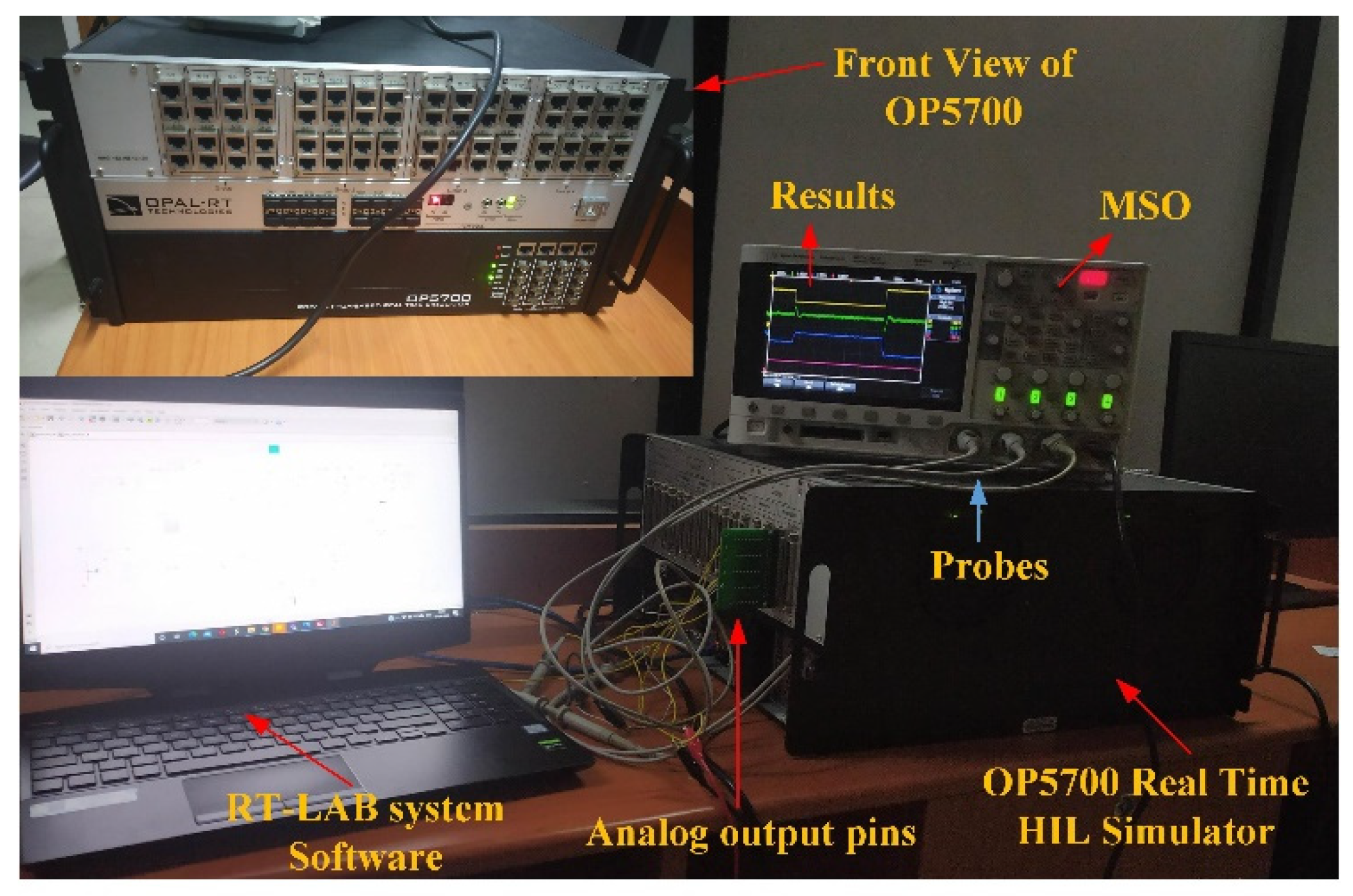
  • To validate the proposed system in real-time simulations with OPAL RT-based real-time simulators are presented.
The rest of the paper is organized as follows: Section 2 describe the system configuration. The conventional EIC is explained in Section 3. In Section 4, the proposed fuzzy logic-based emulated inertia control (FL-EIC) is presented. Section 4 presents the simulation results of the conventional EIC and Proposed FL-EIC. Hardware-In-Loop simulation results are discussed in Section 5. Finally, the conclusions are listed in Section 6.

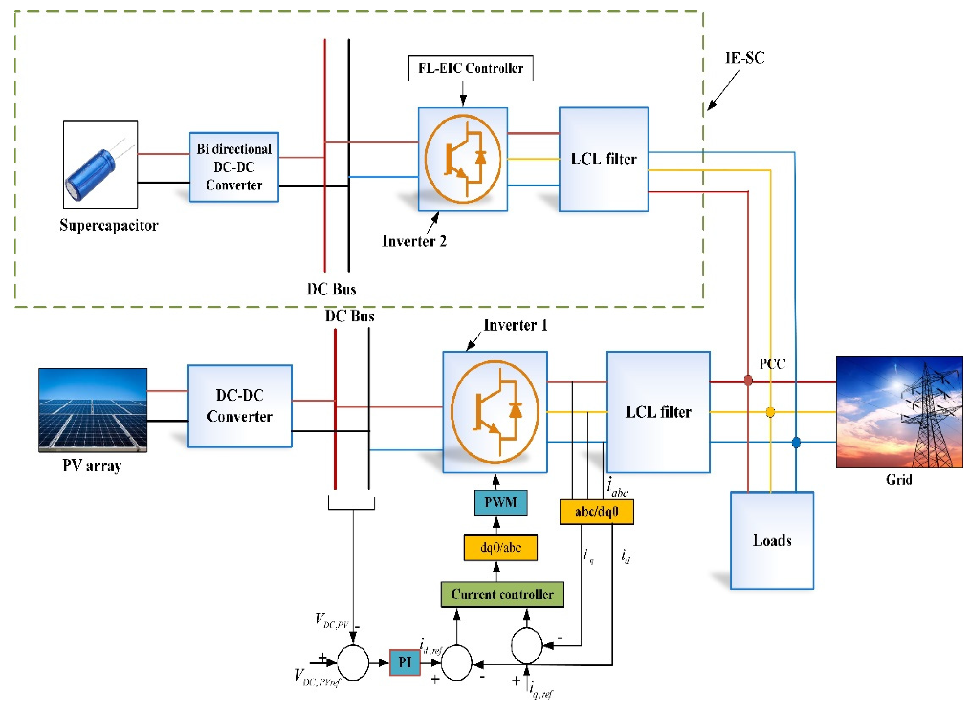
2. System Configuration

The system considered in this paper is shown in Figure 2. It consists of the PV system connected to the grid through a power electronic converter and IE–SC system. The output of the PV is connected to the DC–DC boost converter to step up the voltage. Here, the maximum power point tracking technique is applied at the boost converter to extract maximum power from the PV system. It is connected to the inverter 1 and a filter before connecting it to the grid.
The IE–SC system is used to supply inertia under power imbalances. The IE–SC consists of an SC, and it is connected to the DC bus through the bi-directional DC-DC converter. Then it is connected to the grid through an inverter 2 and a filter. Here, SC injects/absorbs the inertial power under load imbalances. Inverter 1 is connected to the grid as a grid-feeding converter. In contrast, inverter 2 is connected to the grid with the FL-EIC technique to support the inertia of the grid. The IE–SC presented in this paper effectively works as an inertia emulator, and whenever there is a change in frequency, the FL-EIC alters the load angle to supply/absorb the power to/from the grid. A detailed description of the FL-EIC is given in Section 3.

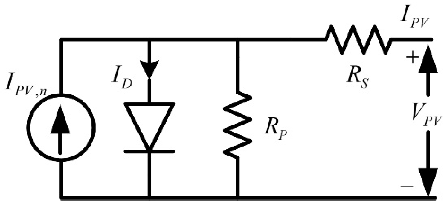
2.1. Modelling of PV System

A critical component of studying a solar PV system is examining the design of the solar cell. The amount of PV power produced is determined by the semiconductor material used in the PV cell and the size of the cell. The PV cell has internal resistance R S , and R P is bound to the diode in a series and parallel framework, as seen in Figure 3. Under the influence of solar radiation, a PV cell produces a direct current voltage V P V and output current I P V . The output current of a PV cell is given as [24]:
I P V = I P V , n ( I 0 ( e V D α V T 1 ) ) V P V + I P V R S R P
where, I P V signifies PV array current, I D is the diode current, I 0 means the reverse saturation current, V D is the diode voltage, V T   is the thermal voltage of the diode, and it is given as
V T = N S k T q
where, N S is the series cells, k is the Boltzmann constant, T is the temperature.
Since solar irradiation is erratic, the perturb and observe (P&O) method is effectively used to collect maximum power from the PV system. The P&O method tracks the maximum power point (MPP) by repeatedly increasing or decreasing the output voltage at the MPP of the Photovoltaic cell. A detailed description of the MPPT can be found in [6].

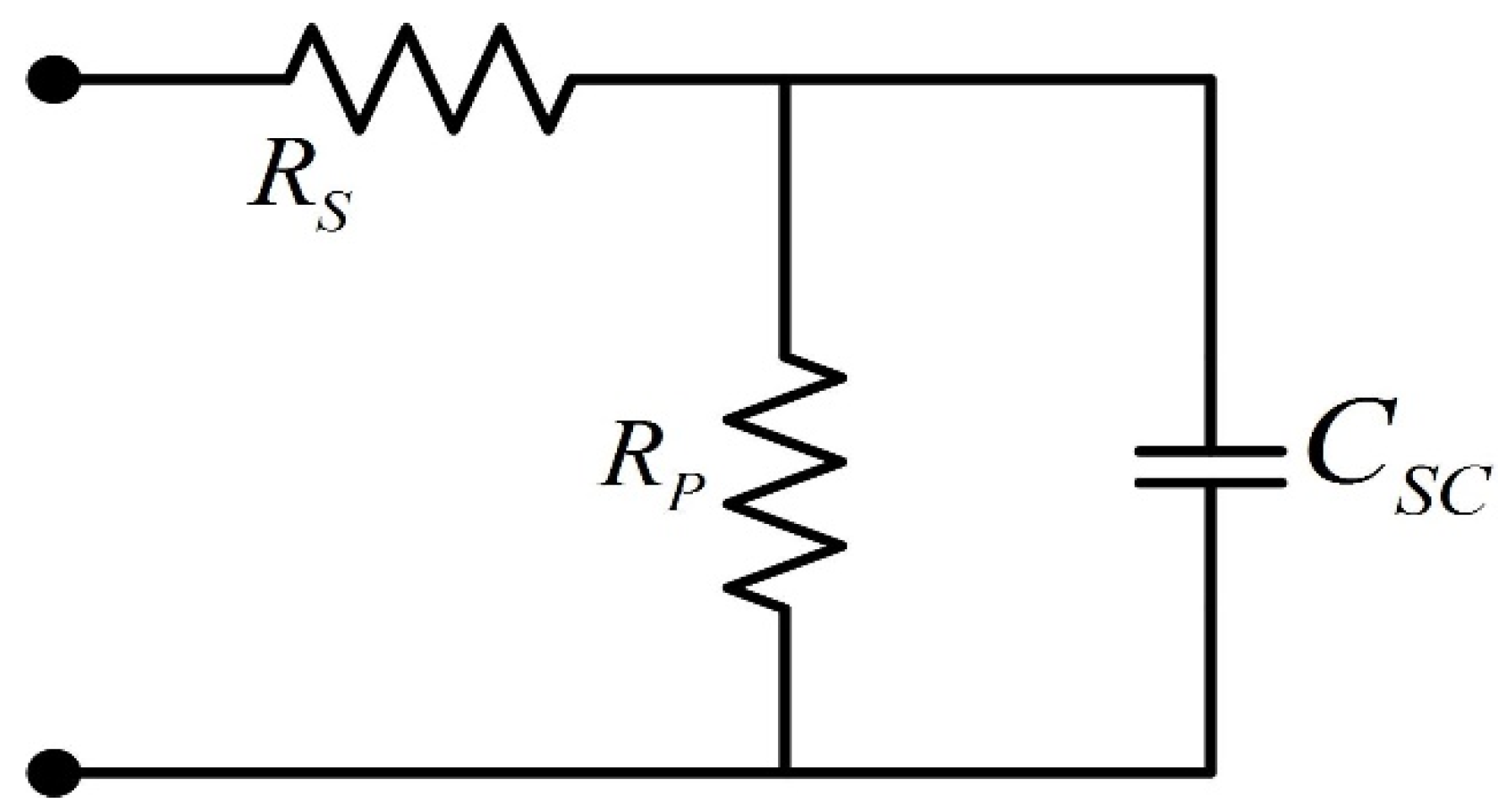
2.2. Supercapacitor in Inertia Emulation

In this section, the inertia emulation from SC is described in the same way as traditional synchronous generators. This description establishes the complex relationships between grid frequency and SC power.
Energy storage devices such as SCs are being deployed to increase the inertia of the power grid. SC energy density makes them suitable for a wide variety of power applications that require high instantaneous power over short periods. The high-power density of SC can supply/absorb power at a faster rate. SC, which has cycle lifetimes well over one million charge/discharge cycles, can withstand short-duration load accompanying without deterioration by discharging to provide load peaks or declines in intermittent generation, and charging as load drops or intermittent generation spikes. As a result of this capability, SC is an excellent choice in inertial response. SC can handle the sudden power variations.
In comparison to DC bus capacitors, SC has more capacitances and hence higher inertia emulation features. SC has the advantages of high power density and a long lifetime. Furthermore, the bi-directional converter at the SC decouples it from the DC bus, enabling a broader range of voltage fluctuations and enhanced inertia.
Inertia emulated by the SC is similar to the inertia of the rotor of a conventional synchronous generator. Despite being a static unit, the SC has high-power density. The FL-EIC technique, when applied to inverter 2 of the IE–SC, may assist active power in the inertial response. With a proper FL-EIC technique at inverter 2 of SC and DC, voltage control in the bi-directional converter of the SC may exchange the energy in the power grid during power imbalance. Theoretically, SC is capable of imitating the rotational inertia of SG.
The simplified SC was built using the models listed in [24,35]. A simplified SC is made up of a bank of SCs and a control mechanism. The bank of SCs can be represented by its equivalent capacitance, CSC. In [24], you can see a detailed explanation of SC dynamics. The equivalent model of SC consists of capacitance, a series internal resistance, and a parallel resistance representing the self-discharging resistance. The equivalent SC circuit is shown in Figure 4.

Selection of Supercapacitor

The capacitance of the SC unit is determined by the requisite power rating, voltage rating, and time period. The restoration time is determined by how quickly power balancing is accomplished. The capacitance value is determined by the peak transient power and the given time period. The nominal voltage of the supercapacitor unit is considered as 220 V for a DC bus voltage of 500 V. Duration of the transient power supply is calculated for the worst case, i.e., step change of 75 % of the rated load for 10–15 s.
The energy balancing equation of SC is:
1 2 × C S C × V S C 2 = η × P S C × t
where P S C is the required power rating of the SC in watts, t is the required duration of the supply in seconds. From (1), C S C is found to be 9.29 F. The SC parameters are given in Table 1.

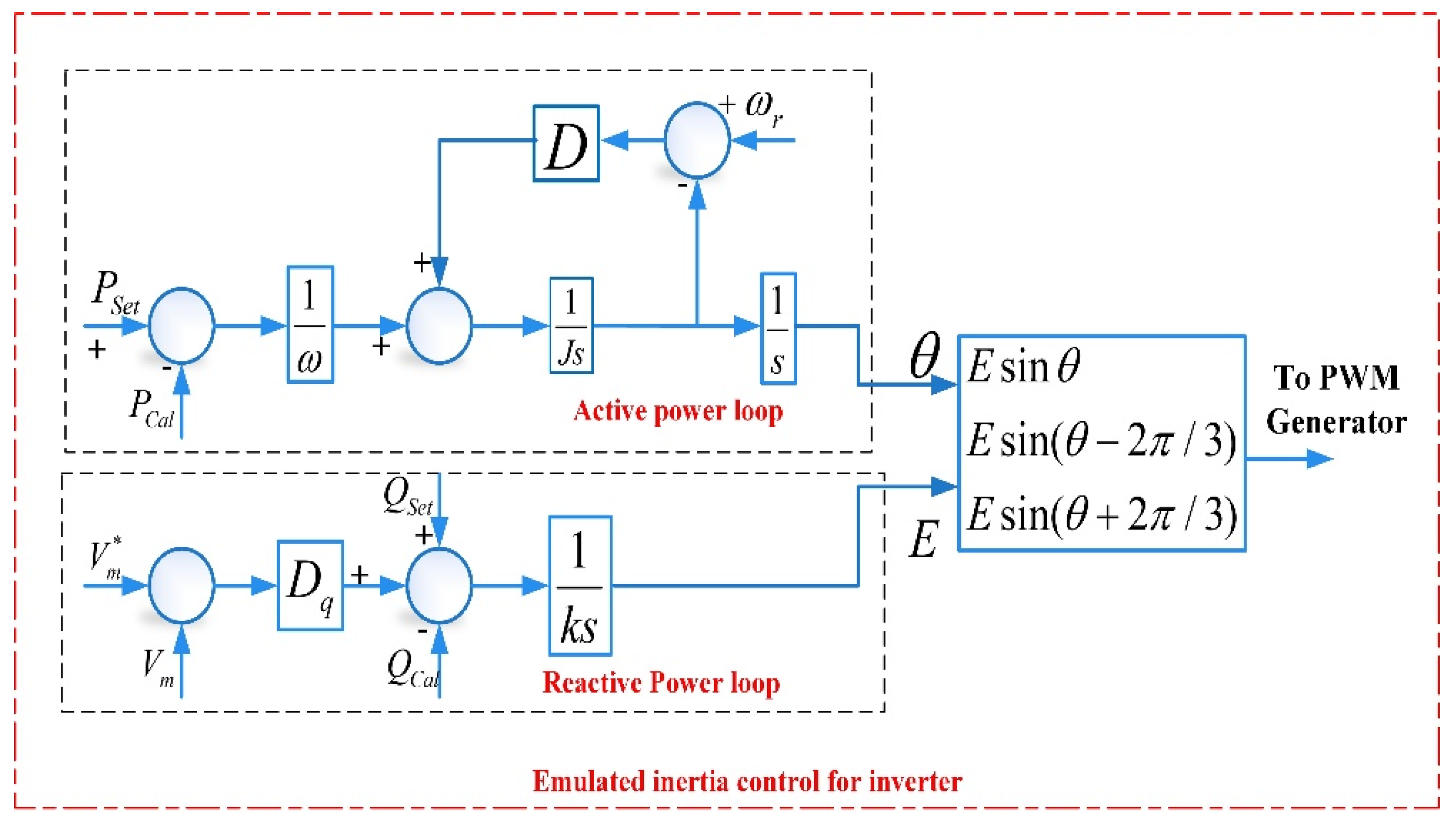
3. Conventional Inertia Emulation Control

Figure 5 illustrates the conventional EIC [6] diagram proposed in the literature. EIC uses two loops to generate the reference voltage. The active power loop uses a swing equation to produce load angle ( θ ), whereas the reactive power loop generates the voltage magnitude ( E ). In the active power loop of EIC, the angular frequency of the grid ( ω r ) is compared with the reference angular frequency ( ω ) to calculate the necessary virtual torque to compensate for the frequency. The virtual torque varies with the variation in frequency, and this, in turn, alters the load angle of the IE–SC. Similarly, the reference magnitude of the voltage varies with the reactive power in the system in the reactive power loop of EIC. EIC uses the mathematical model of the synchronous generator to offer inertia. EIC applied to the power electronic inverter transforms the inverter into a synchronous generator in the inertial response. Whenever there is a change in frequency, the EIC algorithm injects the inertial power by changing the load angle of the inverter [36].
The following equations describe the core algorithm of EIC [34]
( P s e t P c a l ) / ω D P ( ω ω r ) = J d ω d t
d θ d t = ω
1 k ( Q s e t Q c a l ) + D q ( V m * V m ) d t = E
Here, P S e t and Q S e t denote the reference active and reactive power, P C a l and Q C a l denote the measured active and reactive power of the system, D P and D q denote the frequency and voltage drooping coefficients, J and k describe the system inertia and integrator gain, and ω and θ denote angular frequency and load angle, respectively. ω r is the reference angular frequency, V m and V m * are the voltage magnitude and reference voltage magnitude, respectively, and E is the voltage magnitude.
Generally, the strength of the grid is assessed by the short circuit ratio (SCR). The SCR value is more than 3 for high inertia grids, the SCR value for low inertia grid is between 2 and 3, and the SCR value for the very low inertia grid is less than 2. In this paper, SCR value is chosen between 2 and 3. The non-linear behavior of the EIC is observed from (4) to (6). This non-linear behavior exists if it is connected to a low inertia grid also. Hence, the use of a nonlinear controller such as the fuzzy logic (FL) technique manages these nonlinearities and enhances the performance of the EIC.

4. Fuzzy Controller for Inertia Enhancement

4.1. Fuzzy Logic Control

Fuzzy logic is an empirical supervised learning methodology that uses human intuition or experience to set up a control system [35]. Fuzzy logic is a way of translating linguistic information into a statistical model; it converts human decision-making stages into numerical set-based control rules.
Owing to its ease, accuracy and robustness, FL has been employed in various engineering and science fields even for resolving control problems [36]. FL is capable of handling system non-linearity problems in the operation and control of the power system [37]. Over the decades, fuzzy logic has been commonly applied to alter the gains of the controller based on if-then rules. The structure of an FL system shown in Figure 6 consists of a series of rules for regulating the inference engine. With the aid of the fuzzifier, different inputs can be fuzzified and fed to the inference engine. The logical output of the inference engine is de-fuzzified to produce the output. Fuzzy control techniques are classified into Mamdani and Takagi–Sugeno fuzzy rules [38]. In this paper, the Mamdani FL is utilized to enhance the inertia of a grid.

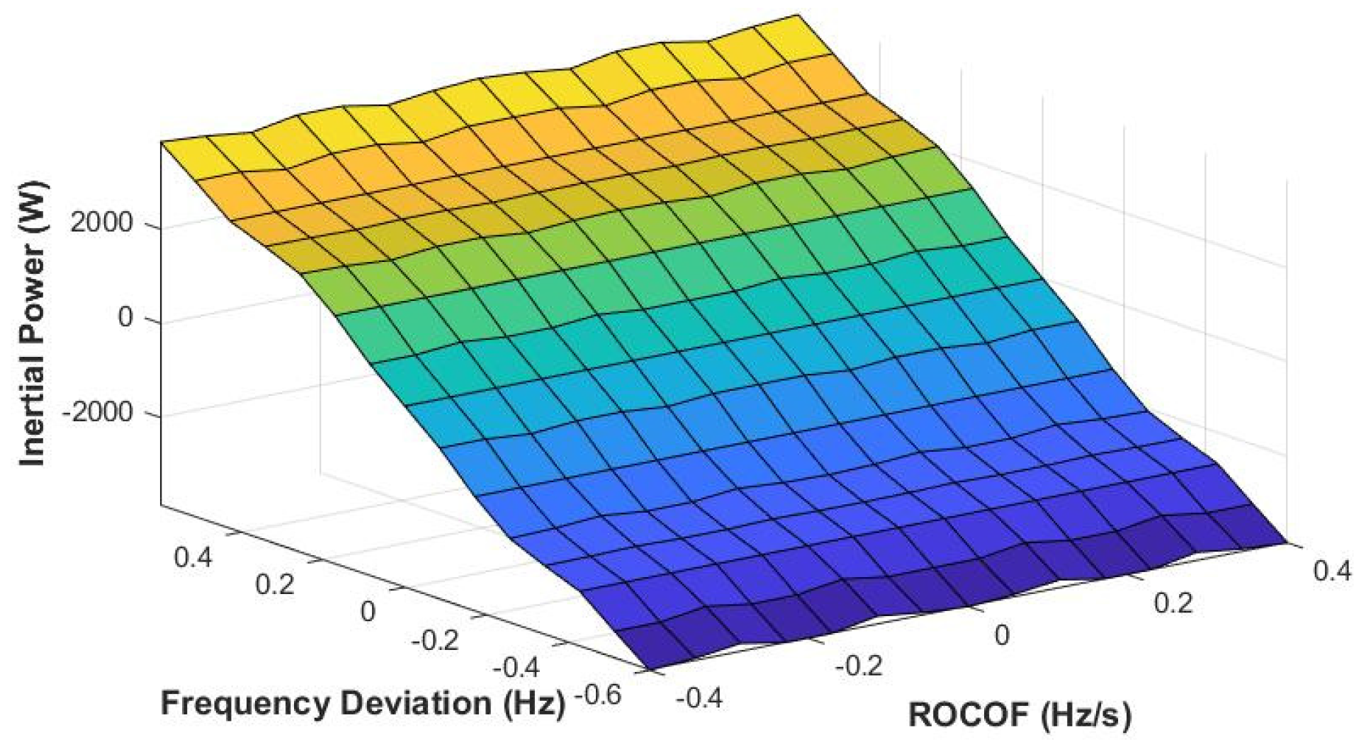
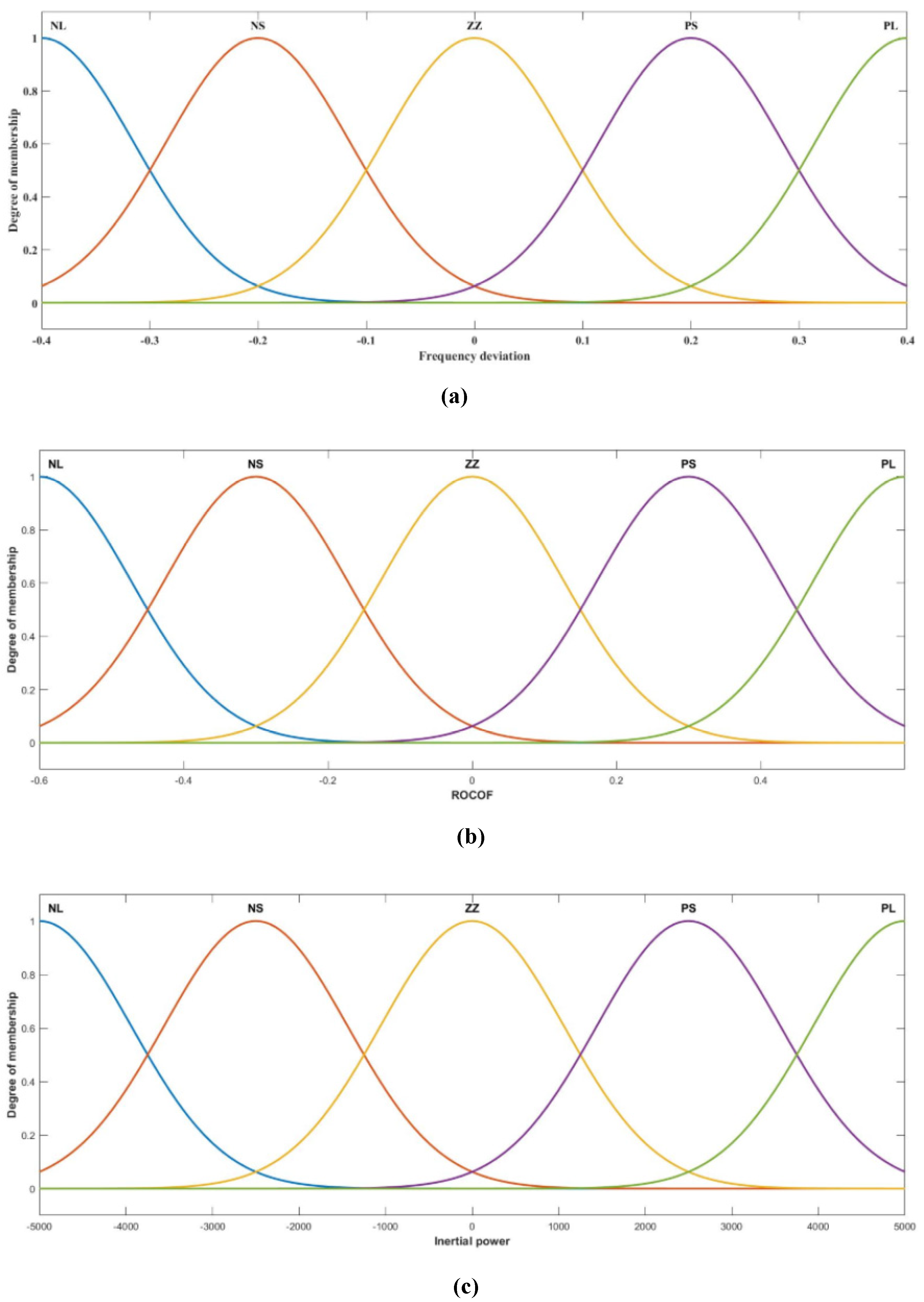
4.2. Fuzzy Inputs and Outputs

The effective performance of the fuzzy system is strongly dependent on the accurate selection of the inputs. Frequency deviation ( Δ f ) and ROCOF are the key parameters that can impact inertial response, and these are selected as inputs for the fuzzy system to enhance the inertia. The inputs of the fuzzy system are determined at the PCC in Figure 1. The inputs of FL can be identified as:
z = [ z 1 z 2 ] = [ Δ f d f d t ]
Usually, fuzzification is used to transform the real inputs into fuzzy values. In the fuzzy inputs and output membership functions, PL is the positive large (implies large positive deviation), PS is the positive small (implies small positive deviation), ZZ implies usual quantity, NL is negative large (large negative deviation), and NS is negative small. The output is an estimated inertial power P I n e r t i a that has been applied to the EIC. The fuzzy rules are created. An appropriate inertial power P I n e r t i a signal is generated as per frequency deviations and ROCOF under power imbalances. The Gaussian membership functions of fuzzy inputs and outputs are shown in Figure 7 and mathematically represented as:
μ ( z 1 = Δ f ) = e x p ( z 1 c 1 ) 2 2 σ 1 2 ; μ ( z 2 = d f d t ) = e x p ( z 2 c 2 ) 2 2 σ 2 2
μ ( y = P I n e r t i a ) = e x p ( y c y ) 2 2 σ y 2
where, μ ( z 1 = ω ) , μ ( z 2 = d ω d t ) , μ ( y = P I n e r t i a ) are the membership functions of frequency deviation, ROCOF and inertial power. c 1 , c 2 , c y are the mean of the membership function of frequency deviation, ROCOF and inertial power. σ 1 , σ 2 , σ y represent the standard deviations of the membership function of frequency deviation, ROCOF and inertial power.
Initially, fuzzification is utilized to transform actual inputs into fuzzy values. Table 2 summarizes the properties of input and output membership functions. The mean of the membership is defined as the range of inputs/outputs to several partitions (number of partitions = number of membership functions − 1).
The standard deviation of each membership function is calculated based on the below equation
σ x = 1 , 2 , y = 0.5 × c 1 , 2 , y ( 2 l n ( 0.5 ) )
Subsequently, these fuzzy values are fed to the fuzzy inference engine with the rules. The fuzzy rules are formulated using the “if-then” condition, and those are tabulated in Table 3. This paper uses the center of gravity defuzzification method to convert the fuzzy output to finite values. Figure 8 shows the surface plot of FL, which represents the amount of inertial power required for various frequency deviations and ROCOF. The required inertial power is calculated based on frequency deviation and ROCOF of the system as per the Figure 8.

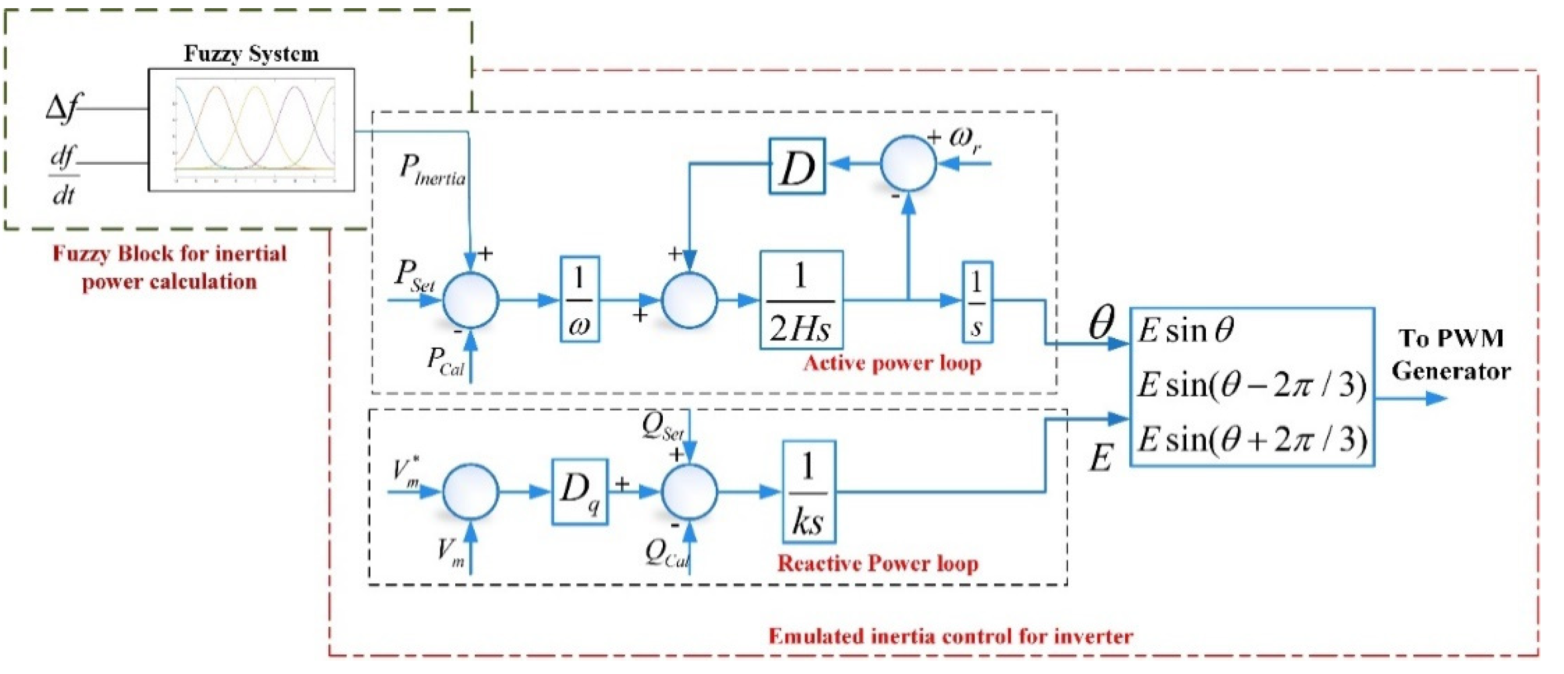
4.3. FL-EIC for Inertia Enhancement

Figure 9 illustrates the proposed FL-EIC technique for inertia enhancement. The FL block estimates the required inertial power in transients. In power imbalances, the signal adjusts to decrease the frequency deviation. The appropriate identification of the fuzzy rules has an adequate performance of the proposed FL-EIC. Therefore, it plays a crucial role in stabilizing the frequency and enhancing the inertial response. The estimated performance is attained when FL is altered by the selected membership functions. Hence, the EIC technique and FL stabilize the frequency, provide sufficient inertia, and effectively reduce the frequency nadir point/overshoot point.

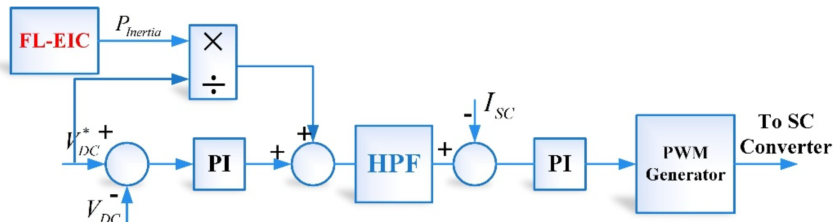
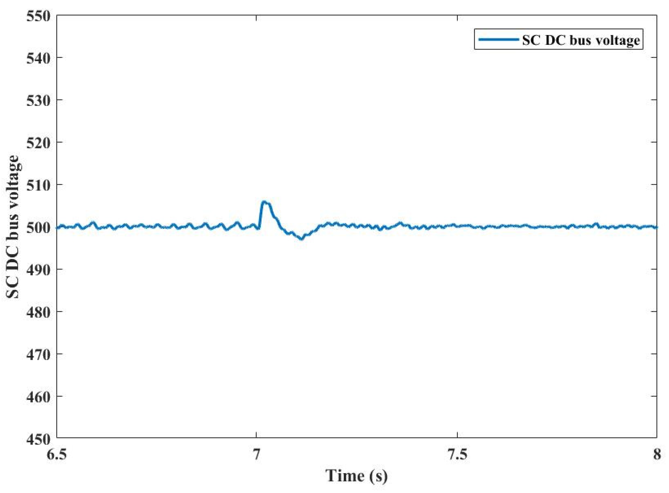
4.4. DC Voltage Controller at SC Bi-Directional Converter

Figure 10 depicts the fundamental control mechanisms of an SC system. The bi-directional control at the SC is controlled, enabling SC voltage VDC to accurately track the reference voltage. Furthermore, to perform inertia emulation, a DC voltage control at SC is used, which explicitly relates the frequency to the SC voltage employed, as seen in Figure 9. The correlation between frequency and SC voltage is made in the DC voltage controller to decrease in frequency peak in the recovery phase. The requisite inertial current released/absorbed from the SC is determined using the appropriate inertial power calculated by the FL-EIC from Figure 9. The inertial reference current is added to the reference current calculated from the PI control. The high-pass filter is used to estimate the required amount of inertial current needed to handle SC.
However, SC has drawbacks. SC has high-power density, which means it can provide a lot of power, but since it has low-energy density, it can only provide power for limited periods. Furthermore, when a supercapacitor discharges, the voltage gradually decreases. Correspondingly, when it loads, the voltage rises linearly. The advancement of SC would make this method more commercially appealing.

5. Simulation Results

The proposed system is modelled in MATLAB/Simulink, and system parameters are tabulated in Table 4. In this section, the proposed FL-EIC is compared with the conventional EIC to demonstrate the effectiveness of the proposed FL-EIC. A step-change in the load creates the frequency event. The variation in frequency and estimated inertial power calculated by two techniques are analyzed.

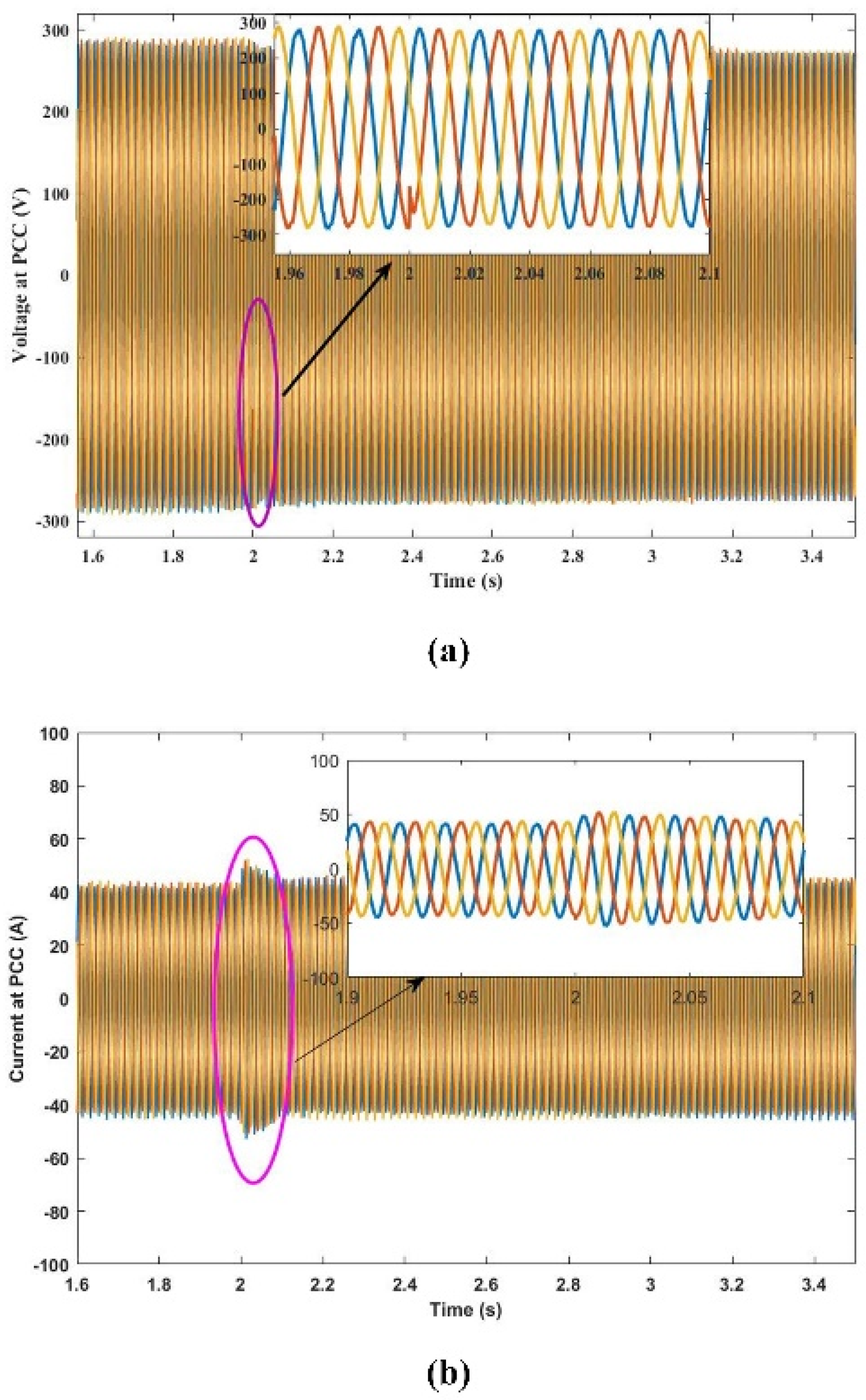
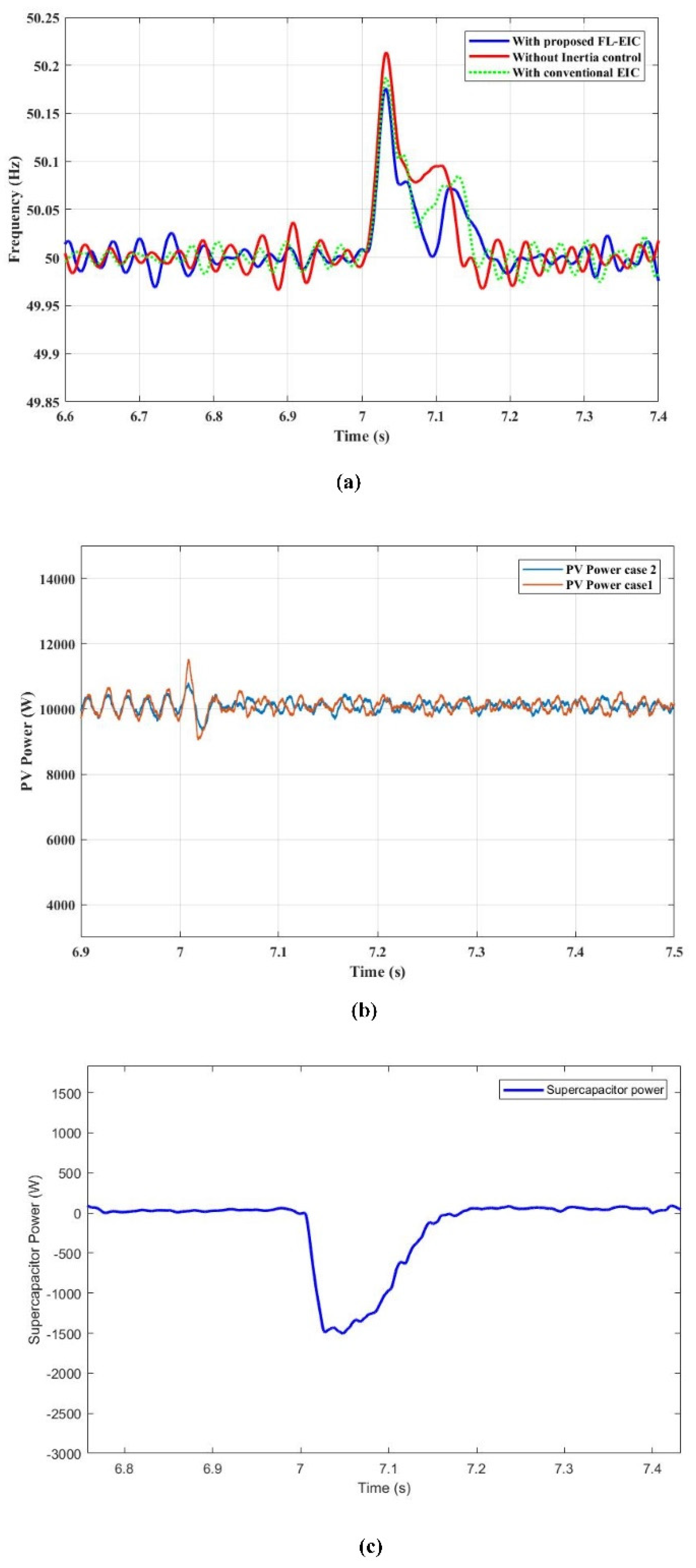
5.1. Frequency Output Analysis under Sudden Load Change

Some sets of simulations are executed to assess the performance FL-EIC based IE–SC under load variations. The following simulations are considered:
  • Case 0: System without inertia control
  • Case 1: System with conventional EIC as per the reference [36].
  • Case 2: System with IE–SC system based on FL-EIC.
In this context, the irradiance level of a PV system is presumed to be 1000 W/m2 and it is capable of generating its maximum power. A baseload of 8000 W is attached to the point of common coupling, and the excess amount of power generated by PV is exported to the grid. The variation in the load is intended to produce a power imbalance at 2 s. This power imbalance results in frequency deviations. The comparison of frequency response in different cases shows the effect of IE–SC based on FL-EIC in the low inertia grid. In Figure 11, the dynamic response of frequency, the output from the PV generator and inertial response from IE–SC with FL-EIC are shown. In case 0, the frequency nadir (lowest frequency point) is more without any additional support, and frequency oscillations are more when the step increase in load is activated. From Figure 11a, the frequency nadir is observed as 49.78 Hz without any additional inertia support. Compared to case 0 and case 1, the frequency nadir is limited to 49.85 Hz with IE–SC based on the FL-EIC technique. Figure 11b shows that oscillations in PV power are more in case 1, and oscillations in PV power are less with FL-EIC. Figure 11c reveals that the inertial power in case 2 is supplied by the FL-EIC technique to provide quick power support. Figure 12a,b shows us the voltage and current at the PCC for an under-frequency event. As expected, waveforms of the voltages are controlled as clean sinusoidal while the proposed controller maintains the DC bus voltage at the SC at constant, as seen in Figure 13. A finding is that the proposed FL-EIC system would not jeopardize the power grid’s normal operation. The load angle of the voltage at PCC increases, as induced by the FL-EIC. The current at 2 s (under frequency event) increases abruptly to supply the power in an inertial response. The increase in current is supplied by inverter2 at the SC. Table 5 lists comparisons of the performance of different testing conditions during a rapid rise in load.
Figure 14 verifies that the performance of the FL-EIC-based IE–SC system under step decreases in load. A rapid shift in load was simulated at t = 7 s to create a mismatch in generation and demand, leading to frequency oscillations. In case 0, the frequency peak is raised to 50.22 Hz without any additional inertial support when the step decrease in the load is modelled. The frequency peak is less with IE–SC based on conventional EIC, whereas the frequency rise is limited to 50.176 Hz with IE–SC based on the proposed FL-EIC technique. Figure 14b illustrates that PV power oscillations are more in case 1 and less in case 2 under sudden decrease in load. Figure 14c shows the amount of inertial power absorbed by the IE–SC based on FL-EIC. Figure 15a,b shows us the voltage and current at the PCC for an under-frequency event. As predicted, the voltage waveforms are regulated as clean sinusoidal while the proposed controller maintains the DC bus voltage at SC constant, as seen in Figure 16. One of the results is that the new FL-EIC method will not endanger the regular operation of the system. The load angle of the voltage at PCC decreases, as induced by the FL-EIC. The current at 7 s (over frequency event) increases abruptly to supply the power in an inertial response. The increase in current is supplied by inverter2 at the SC. Table 6 compares the performance of different testing conditions during a rapid decrease in load. The FL-EIC technique considers both the loops (frequency deviation and ROCOF) to estimate the inertial power to decrease the frequency nadir and improve frequency stability when a step changes in load.

5.2. Inertia Responses for PV Irradiation Variations
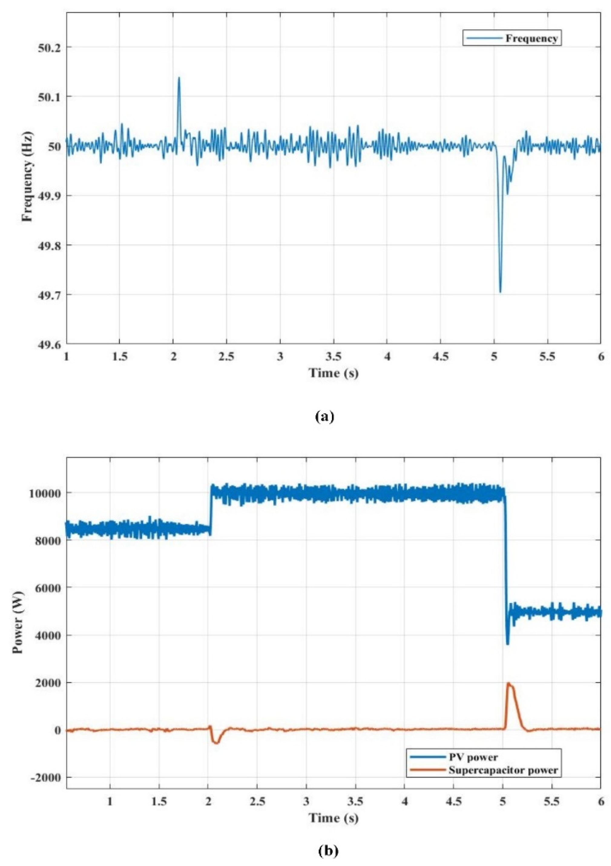
This scenario tests the performance of the FL-EIC-based IE–SC under different PV irradiation levels. Initially, the PV irradiation is assumed as 800 W/m2. To observe the effect of FL-EIC-based IE–SC under different irradiations, the frequency response and inertial power supported by IE–SC is plotted in Figure 17.
The irradiation of PV is increased to 1000 W/m2 at 2 s, and decreased to 500 W/m2 at 5 s. The variations in irradiation levels result in PV power fluctuations, and leads to a power imbalance in the system. This power imbalance induces frequency variations.
As seen in Figure 17a, at t = 2 s the system frequency rise is arrested at 50.13 Hz with IE–SC based on FL-EIC. The frequency dip is arrested at 49.71 Hz with a decrease in the PV irradiation level at 5 s. The inertial power is absorbed at 2 s and released at 5 s, as shown in Figure 17b. It is clear from this scenario that the frequency response is improved with the proposed system under different irradiation levels. Figure 18 depicts the DC bus voltage variations at the SC during PV power variations.

6. HIL Results

HIL evaluation is carried out to evaluate the feasibility and performance of the proposed system. The setup required for Hardware-In-Loop (HIL) implementation and corresponding results are given in this section. The OP5700 (OPAL-RT-based real-time simulator) is a digital simulator capable of real-time operation, i.e., it can solve power system equations fast enough to continuously produce output conditions that realistically represent conditions in real network conditions. The RT-Lab is a comprehensive software used to interact circuits from MATLAB to OP5700. The grid-connected proposed system, along with controllers, are deposited into the OP5700. The detailed plant model is implemented on OPAL-RT, which can closely replicate physical systems and control dynamics. The OPAL-RT set is shown in Figure 19.

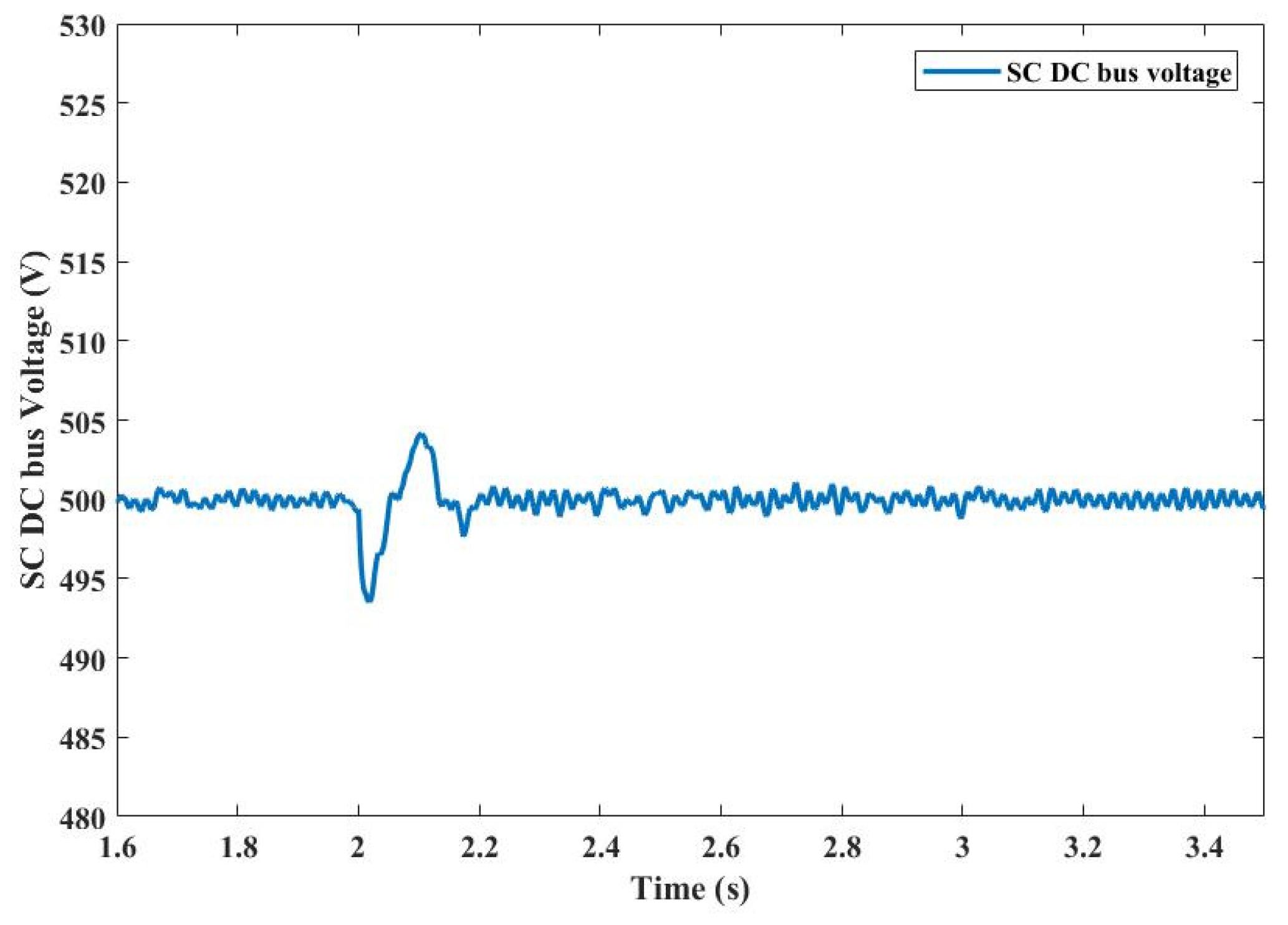
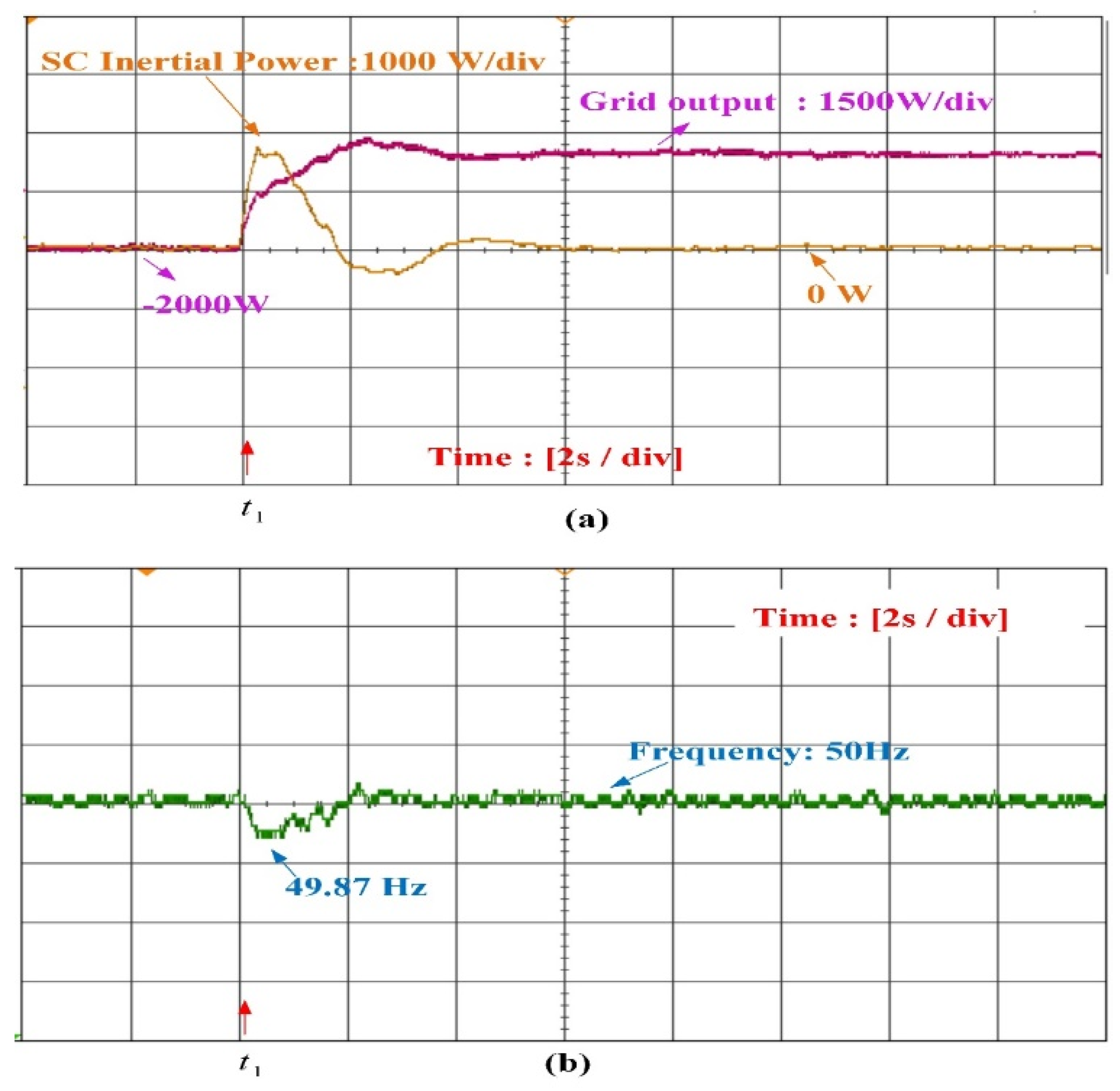
6.1. Step Change in Load

In this scenario, the objective is to demonstrate the performance of the proposed FL-EIC for sudden changes in load conditions. Source side (PV) variations are not considered in this scenario. The load change is modelled at t = t1 s, and consequently, the frequency drops from 50 Hz to 49.86 Hz. Whenever there is a change in frequency from nominal value, then and there the proposed FL-EIC technique activates to inject the required inertial power from SC to the grid. The frequency nadir for this scenario is effectively limited in real-time also. At t = t1 s, the inertial response from the SC is released to compensate for the imbalance. The variation in inertial response from SC and frequency variations for this scenario is shown in Figure 20. Hence, the FL-EIC controlled grid-connected IE–SC system resembles the synchronous generator’s inertial characteristics in load variations. The FL-EIC technique alters the load angle to inject/absorb the power under frequency deviations. Under frequency deviations, the IE–SC system was modelled in such a manner that the highly variable inertial power was supplied/absorbed by the SC.

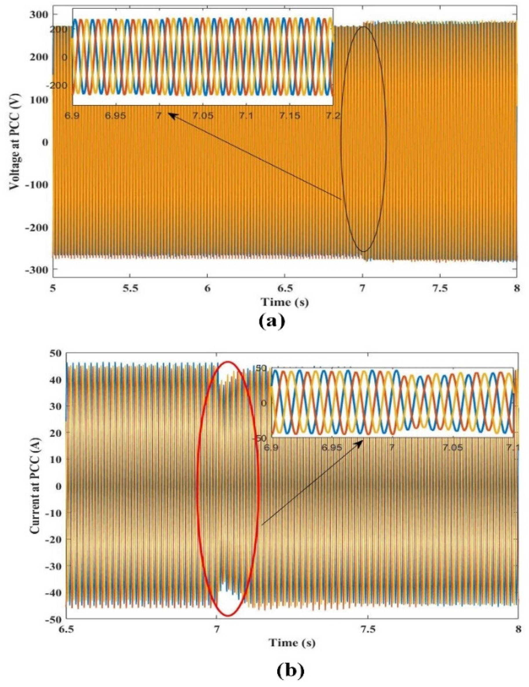
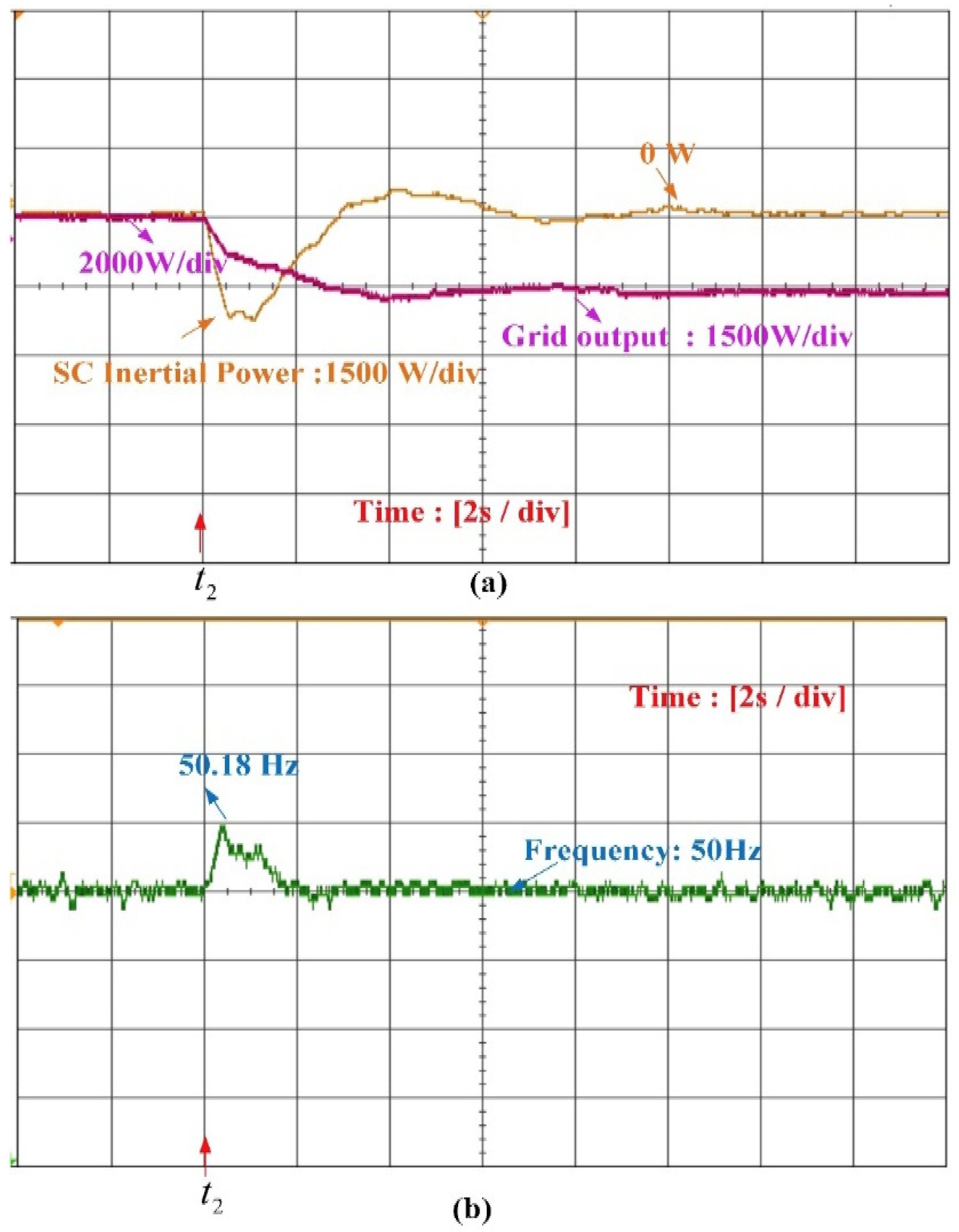
6.2. Step Change in PV Irradiation

In this scenario, a power imbalance is created from variations in the source side to test the evaluation FL-EIC. It was assumed that the PV system operates around 600 irradiances, and the load estimated at the PCC was 8000 W. In the initial condition, the load at the PCC was supplied by the PV and grid. At t = t2 s, a step increase in the irradiation level is modelled to create the power imbalance. This power imbalance creates a frequency rise. Whenever there is an increase in the frequency, the FL-EIC generates the inertial power signal. The FL-EIC technique is used to absorb the extra power in the inertial response to limit the frequency rise at 50.18 Hz, as shown in Figure 21. This transition creates an oscillation in grid frequency, and the proposed FL-EIC technique is able to handle grid frequency variations from the source side also.

7. Conclusions

In this paper, an FL-EIC technique is proposed for IE–SC inertia emulators to improve the inertial response of the grid. Initially, the necessity of an inertia emulator in the low inertia grid is highlighted. The idea behind the FL-EIC is that the required inertial power signal is generated based on inputs (frequency deviation and ROCOF), and the output of the fuzzy controller is fed to the EIC technique to alter the load angle of the inverter to adjust the power and stabilize frequency. The effectiveness of the proposed FL-EIC is compared with the conventional EIC. Furthermore, real-time simulation verification is demonstrated for FL-EIC in the inertial response. Real-time simulation results proved that the proposed EIC was able to handle the sudden load transitions and source-side variations. Moreover, the limitation of the inertia emulation along with design parameters of the proposed work is identified. The validation of continuous variation of source and load is planned for the future, along with hardware implementation of the proposed work.

Author Contributions

Conceptualization—R.K.S., K.P. and E.D.T.; methodology—R.K.S., K.P. and E.D.T., software—R.K.S.; validation—R.K.S., K.P. and E.D.T.; formal analysis—R.K.S., K.P. and E.D.T.; investigation—R.K.S., K.P. and E.D.T.; resources—R.K.S., K.P. and E.D.T.; data curation—R.K.S., K.P. and E.D.T.; writing—original draft preparation R.K.S., K.P. and E.D.T.; writing—review and editing—R.K.S., K.P. and E.D.T.; visualization—R.K.S., K.P. and E.D.T.; supervision—K.P. and E.D.T.; project administration—E.D.T.; funding acquisition—K.P. and E.D.T. All authors have read and agreed to the published version of the manuscript.

Funding

This research work was partially supported by the Italian Ministry for Education, University and Research under the grant PRIN-2017K4JZEE “Planning and flexible operation of micro-grids with generation, storage and demand control as a support to sustainable and efficient electrical power systems: regulatory aspects, modeling and experimental validation”.

Institutional Review Board Statement

Not applicable.

Informed Consent Statement

Not applicable.

Data Availability Statement

Not applicable.

Acknowledgments

The authors of this research work are grateful to the “Fund for Improvement of S&T infrastructure in universities & higher educational institutions (FIST)” of the Department of Science & Technology (DST)—Government of India—for sanctioning and funding Project Grant No.: SR/FST/ETI-420/2016(C) to establish the PHIL/HIL set up used in this research work.

Conflicts of Interest

The authors declare no conflict of interest.

References

  1. Zervos, A. Renewables 2018 Global Status Report; Ren21: Paris, France, 2018. [Google Scholar]
  2. Tamrakar, U.; Shrestha, D.; Maharjan, M.; Bhattarai, B.P.; Hansen, T.M.; Tonkoski, R. Virtual Inertia: Current Trends and Future Directions. Appl. Sci. 2017, 7, 654. [Google Scholar] [CrossRef]
  3. Zhong, Q.-C.; Weiss, G. Synchronverters: Inverters That Mimic Synchronous Generators. IEEE Trans. Ind. Electron. 2011, 58, 1259–1267. [Google Scholar] [CrossRef]
  4. Ratnam, K.; Palanisamy, K.; Yang, G. Future low-inertia power systems: Requirements, issues, and solutions—A review. Renew. Sustain. Energy Rev. 2020, 124, 109773. [Google Scholar] [CrossRef]
  5. Nguyen, H.T.; Yang, G.; Nielsen, A.H.; Jensen, P.H. Frequency stability enhancement for low inertia systems using synthetic inertia of wind power. In Proceedings of the 2017 IEEE Power & Energy Society General Meeting, Chicago, IL, USA, 16–20 July 2017; pp. 1–5. [Google Scholar]
  6. Sarojini, R.K.; Palanisamy, K. Emulated Inertia Control for the Stand-Alone Microgrid with High Penetration of Renewable Energy Sources. Int. J. Renew. Energy Res. 2020, 10, 831–842. [Google Scholar]
  7. Bose, U.; Chattopadhyay, S.K.; Chakraborty, C.; Pal, B. A Novel Method of Frequency Regulation in Microgrid. IEEE Trans. Ind. Appl. 2019, 55, 111–121. [Google Scholar] [CrossRef]
  8. Ashabani, M.; Freijedo, F.D.; Golestan, S.; Guerrero, J. Inducverters: PLL-Less Converters With Auto-Synchronization and Emulated Inertia Capability. IEEE Trans. Smart Grid 2016, 7, 1660–1674. [Google Scholar] [CrossRef]
  9. Xiong, L.; Zhuo, F.; Wang, F.; Liu, X.; Chen, Y.; Zhu, M.; Yi, H. Static Synchronous Generator Model: A New Perspective to Investigate Dynamic Characteristics and Stability Issues of Grid-Tied PWM Inverter. IEEE Trans. Power Electron. 2016, 31, 6264–6280. [Google Scholar] [CrossRef]
  10. Peng, Q.; Fang, J.; Yang, Y.; Liu, T.; Blaabjerg, F. Maximum Virtual Inertia from DC-Link Ca-pacitors Considering System Stability at Voltage Control Timescale. IEEE J. Emerg. Sel. Top. Circuits Syst. 2021, 11, 79–89. [Google Scholar] [CrossRef]
  11. Fang, J.; Li, H.; Tang, Y.; Blaabjerg, F. Distributed Power System Virtual Inertia Implemented by Grid-Connected Power Converters. IEEE Trans. Power Electron. 2018, 33, 8488–8499. [Google Scholar] [CrossRef] [Green Version]
  12. Dreidy, M.; Mokhlis, H.; Mekhilef, S. Inertia response and frequency control techniques for renewable energy sources: A review. Renew. Sustain. Energy Rev. 2017, 69, 144–155. [Google Scholar] [CrossRef]
  13. Su, Y.; Li, H.; Cui, Y.; You, S.; Ma, Y.; Wang, J.; Liu, Y. An Adaptive PV Frequency Control Strategy Based on Real-Time Inertia Estimation. IEEE Trans. Smart Grid 2021, 12, 2355–2364. [Google Scholar] [CrossRef]
  14. Subramaniam, U.; Vavilapalli, S.; Padmanaban, S.; Blaabjerg, F.; Holm-Nielsen, J.B.; Almakhles, D. A Hybrid PV-Battery System for ON-Grid and OFF-Grid Applications—Controller-In-Loop Simulation Validation. Energies 2020, 13, 755. [Google Scholar] [CrossRef] [Green Version]
  15. Delille, G.; François, B.; Malarange, G. Dynamic frequency control support by energy storage to reduce the impact of wind and solar genera- tion on isolated power system’s inertia. IEEE Trans. Sustain. Energy 2012, 3, 931–939. [Google Scholar] [CrossRef]
  16. Rakhshani, E.; Rodriguez, P. Inertia Emulation in AC/DC Interconnected Power Systems using Derivative Tech-nique considering Frequency Measurement Effects. IEEE Trans. Power Syst. 2017, 32, 3338–3351. [Google Scholar] [CrossRef]
  17. Sarojini, R.K.; Palanisamy, K.; Sanjeevikumar, P.; Nielsen, J.B.H. Inertia emulation control technique based fre- quency control of grid-connected single-phase rooftop photovoltaic system with battery and supercapacitor. IET Renew. Power Gener. 2020, 14, 1156–1163. [Google Scholar] [CrossRef]
  18. Fang, J.; Tang, Y.; Li, H.; Li, X. A Bat- tery/Ultracapacitor Hybrid Energy Storage System for Im-plementing the Power Management of Virtual Synchronous Generators. IEEE Trans. Power Electron. 2018, 33, 2820–2824. [Google Scholar] [CrossRef]
  19. Sharma, S.; Varshney, L.; Elavarasan, R.M.; Vardhan, A.S.S.; Vardhan, A.S.S.; Saket, R.K.; Subramaniam, U.; Hossain, E. Performance Enhance- ment of PV System Configurations under Partial Shading Conditions Using MS Method. IEEE Access 2021, 9, 56630–56644. [Google Scholar] [CrossRef]
  20. Gonzalez-Longatt, F.M.; Alhejaj, S. Enabling inertial response in utility-scale battery energy storage system. In Proceedings of the 2016 IEEE Innovative Smart Grid Technologies—Asia (ISGT-Asia), Melbourne, VIC, Australia, 28 November–1 December 2016; pp. 605–610. [Google Scholar] [CrossRef] [Green Version]
  21. Brogan, P.V.; Best, R.J.; Morrow, D.J.; McKinley, K.; Kubik, M.L. Effect of BESS Response on Frequency and RoCoF During Underfrequency Transients. IEEE Trans. Power Syst. 2019, 34, 575–583. [Google Scholar] [CrossRef] [Green Version]
  22. Hosseinipour, A.; Hojabri, H. Virtual inertia control of PV systems for dynamic performance and damping en-hancement of DC microgrids with constant power loads. IET Renew. Power Gener. 2018, 12, 430–438. [Google Scholar] [CrossRef]
  23. Ratnam, K.S.; Palanisamy, K.; Teekaraman, Y.; Nikolovski, S.; Baghaee, H.R. An enhanced emulated inertia control for Grid-connected PV system with HESS in a weak grid. Energies 2021, 14, 1721. [Google Scholar]
  24. Zhu, J.; Hu, J.; Hung, W.; Wang, C.; Zhang, X.; Bu, S.; Li, Q.; Urdal, H.; Booth, C.D. Synthetic Inertia Control Strategy for Doubly Fed Induction Generator Wind Turbine Generators Using Lithium-Ion Supercapacitors. IEEE Trans. Energy Convers. 2018, 33, 773–783. [Google Scholar] [CrossRef]
  25. Zhang, R.; Fang, J.; Tang, Y. Inertia Emulation through Supercapacitor Energy Storage Systems. In Proceedings of the 10th International Conference on Power Electronics and ECCE Asia (ICPE 2019-ECCE Asia), Busan, Korea, 27–30 May 2019; Volume 3, pp. 1365–1370. [Google Scholar]
  26. Sarojini, R.K.; Palanisamy, K. Inertia emulation through supercapacitor for a weak grid. IEEE Access 2021, 9, 30793–30802. [Google Scholar] [CrossRef]
  27. Fang, J.; Yu, J.; Zhang, Y.; Goetz, S.M. An Estimation-Based Solution to Weak-Grid-Induced Small-Signal Stability Problems of Power Converters. IEEE J. Emerg. Sel. Top. Power Electron. 2020, 9, 4558–4572. [Google Scholar] [CrossRef]
  28. Dozein, M.G.; Mancarella, P.; Saha, T.K.; Yan, R. System strength and weak grids: Fun-damentals, challenges, and mitigation strategies. In Proceedings of the Australasian Universities Power Engineering Conference, AUPEC 2018, Auckland, New Zealand, 27–30 November 2018. [Google Scholar]
  29. Cao, X.; Han, M.; Khan, Z.W.; Zhang, L. Design and analysation of DC voltage synchronisation control for a VSC-MTDC based on virtual synchronous generator. IET Gener. Transm. Distrib. 2020, 14, 449–459. [Google Scholar] [CrossRef]
  30. Yap, K.Y.; Sarimuthu, C.R.; Lim, J.M.-Y. Grid Integration of Solar Photovoltaic System Using Machine Learning-Based Virtual Inertia Synthetization in Synchronverter. IEEE Access 2020, 8, 49961–49976. [Google Scholar] [CrossRef]
  31. Chen, Y.-K.; Wu, Y.-C.; Song, C.-C.; Chen, Y.-S. Design and Implementation of Energy Management System With Fuzzy Control for DC Microgrid Systems. IEEE Trans. Power Electron. 2012, 28, 1563–1570. [Google Scholar] [CrossRef]
  32. Hosseinzadeh, M.; Salmasi, F.R. Power management of an isolated hybrid AC/DC micro-grid with fuzzy control of battery banks. IET Renew. Power Gener. 2015, 9, 484–493. [Google Scholar] [CrossRef]
  33. Kim, J.-Y.; Kim, H.-M.; Kim, S.-K.; Jeon, J.-H.; Choi, H.-K. Designing an Energy Storage System Fuzzy PID Controller for Microgrid Islanded Operation. Energies 2011, 4, 1443–1460. [Google Scholar] [CrossRef] [Green Version]
  34. Balasubramani, G.; Thangavelu, V.; Chinnusamy, M.; Subramaniam, U.; Pad-manaban, S.; Mihet-Popa, L. Infrared thermography based defects testing of solar pho- tovoltaic panel with fuzzy rule-based evaluation. Energies 2020, 13, 1343. [Google Scholar] [CrossRef] [Green Version]
  35. Bhattacharjee, C.; Roy, B.K. Fuzzy-supervisory control of a hybrid system to improve contractual grid support with fuzzy proportional-derivative and integral control for power quality improvement. IET Gener. Transm. Sion Distrib. 2018, 12, 1455–1465. [Google Scholar] [CrossRef]
  36. Talaq, J.; Al-Basri, F. Adaptive fuzzy gain scheduling for load frequency control. IEEE Trans. Power Syst. 1999, 14, 145–150. [Google Scholar] [CrossRef]
  37. Bevrani, H.; Daneshmand, P.R. Fuzzy Logic-Based Load-Frequency Control Concerning High Penetration of Wind Turbines. IEEE Syst. J. 2012, 6, 173–180. [Google Scholar] [CrossRef]
  38. Ying, H. Introduction to Fuzzy Control and Modeling. In Fuzzy Control and Modeling; Wiley: Hoboken, NJ, USA, 2010; p. 342. [Google Scholar] [CrossRef]
Figure 1. Various time frames for frequency control [2].
Energies 15 01333 g001
Figure 2. System configuration of a proposed system connected to a low inertia grid.
Energies 15 01333 g002
Figure 3. Ideal single-diode PV Model.
Energies 15 01333 g003
Figure 4. Supercapacitor model.
Energies 15 01333 g004
Figure 5. Conventional emulated inertia control.
Energies 15 01333 g005
Figure 6. Overview of fuzzy logic structure.
Energies 15 01333 g006
Figure 7. Membership function of (a) frequency deviation; (b) ROCOF; (c) Inertial power.
Energies 15 01333 g007
Figure 8. Surface plot of the fuzzy controller.
Energies 15 01333 g008
Figure 9. Fuzzy logic-based emulated inertia control.
Energies 15 01333 g009
Figure 10. DC voltage controller for SC bi-directional converter.
Energies 15 01333 g010
Figure 11. Under-frequency event (a) Frequency, (b) Power from PV, (c) Supercapacitor power.
Energies 15 01333 g011
Figure 12. (a) Voltage and (b) Current at PCC for under-frequency event.
Energies 15 01333 g012
Figure 13. DC bus voltage at SC for under-frequency event.
Energies 15 01333 g013
Figure 14. Over-frequency event (a) Frequency, (b) PV power, (c) supercapacitor power.
Energies 15 01333 g014
Figure 15. (a) Voltage and (b) Current at PCC for over-frequency event.
Energies 15 01333 g015
Figure 16. DC bus voltage at SC for over-frequency event.
Energies 15 01333 g016
Figure 17. PV Power Variations (a) Frequency, (b) PV and supercapacitor power.
Energies 15 01333 g017
Figure 18. DC bus voltage at SC for PV power variations.
Energies 15 01333 g018
Figure 19. Real-time simulation setup.
Energies 15 01333 g019
Figure 20. Load transition under constant irradiation (a) power from SC and grid; (b) frequency.
Energies 15 01333 g020
Figure 21. Source side Variations (a) power from SC and grid; (b) frequency.
Energies 15 01333 g021
Table 1. Supercapacitor parameters.
CharacteristicValueUnit
Nominal voltage220[V]
Maximum operating voltage230[V]
Nominal Capacitance9.29[F]
Internal Series resistance0.18[Ω]
Table 2. Properties of frequency deviation, ROCOF and inertial power membership functions.
Membership FunctionsFrequencyROCOF P I n e r t i a
σ 1 c 1 σ 2 c 2 σ y c y
NL0.08496−0.60.1274−0.41062−5000
NS−0.3−0.2−2500
ZZ000
PS0.30.22500
PL0.60.45000
Table 3. Fuzzy rule base for the proposed control system.
ROCOFFrequency Deviation
NLNSZZPSPL
NLNLNLNSPLPL
NSNLNSNSPSPL
ZZNLNSZZPSPL
PSNLNSPSPSPL
PLNLNSPSPLPL
Table 4. Simulation parameters.
ParameterValue
Nominal frequency (f) Nominal Voltage (V*)
Rated DC bus voltage ( V D C )
PV cell for both PV arrays


PV cell for both PV arrays
DC bus Capacitor
Inverter side inductance ( L 1 ) Load side inductance ( L 2 ) Filter capacitance (C)
Frequency Drooping Coefficient ( D P )
Voltage drooping coefficient ( D q )
Gain (k)
Inertia coefficient ( H S C )
50 Hz
220 V
500 V
VOC = 37.3 V, ISC = 8.2 A
Vm = 30.3 V, Im = 7.5 A
NS = 10, NP = 5
9.29 F, 220 V
3300 µF
2.1 mH, 5 mH
12 µF

50

120

1000 A.s
2.8
Table 5. Comparison table for the sudden load increase.
Case 0Case 1Case 2
Frequency nadir (Hz)49.7749.7949.86
ROCOF (Hz/s)0.270.2420.202
DC bus voltage at SC (V)-487.9497
SC power (kW)-1.611.821
Table 6. Comparison table for the sudden load decrease.
Case 0Case 1Case 2
Frequency nadir (Hz)50.2350.19550.176
ROCOF (Hz/s)0.2650.2420.202
DC bus voltage at SC (V)-510.2507
SC power (kW)-−1.35−1.579
Publisher’s Note: MDPI stays neutral with regard to jurisdictional claims in published maps and institutional affiliations.

