1. Introduction and Theoretical Background
Due to the accelerated expansion of the distribution electric power grid caused by increased consumer demand and the need for increasingly reliable service that complies with regulatory requirements, strong and robust protection of the distribution electric power system is necessary. Investment in protection technologies and devices is very important in order to achieve a certain level of reliability and quality of the electrical power supply. Different power system configurations with their own protection coordination philosophies have unique advantages and disadvantages [
1], which means that each part of the distribution power system must be properly protected to avoid a power outage and its consequences regarding equipment malfunction and failure [
2].
Protective relays are the most important means to meet the aforementioned requirements [
3]. The purpose of the protective relay is to de-energize the faulted part of the distribution power system and prevent the rest of the system from being affected in the event of an abnormal condition or fault, such as a short circuit [
4]. To prevent the aforementioned events and their influence on consumers, the relays are set in coordination with each other. Properly coordinated relays are very important for the power distribution system because poor coordination can have serious consequences on the power system, such as power outages, damage to the equipment and utility station malfunctions.
Protection coordination requires the selection of the protection devices’ settings so that the device responds properly in case of an emergency. Short circuit and load flow analysis are required to obtain correct inputs for relay protection coordination [
5]. The coordination schemes must ensure reliability, selectivity, sensitivity and speed of protection relays.
In distribution systems, one of the basic power system protection strategies is overcurrent protection (I>). Overcurrent relays (OCR) are used as the main protection device due to their lower cost compared to other types of relays [
6]. On the other hand, in transmission power networks OCRs are used only as backup protection, while distance relays are used as a primary protection of transmission lines. This was done due to their relatively high time delays (the problem of OCR selectivity). However, distance relays are usually not used in distribution networks because they represent a significantly much costlier solution compared to using standard OCRs [
7]. Therefore, OCR coordination in a power distribution network is an important concern for a protection engineer. It must be noted that in active networks (with distributed generation units) OCRs are used in junction with under/over voltage protection devices, under/over frequency protection devices, and other devices. Usually, numerical relays have all those protection functions integrated in a single device.
When a fault occurs in the power system, the current magnitude increases [
8]. The overcurrent relays measure the fault current and compare it with the predefined threshold values. When the current level rises above the threshold, a trip command is issued after a predefined time delay, and the corresponding circuit breaker opens its contacts and isolates the faulted area.
In
Section 2 of this paper the authors have critically examined the usage of overcurrent relays, accentuating the circumstances in which each type of relay should be used. A calculation procedure for plug settings multiplier (or pick-up current) determination was laid out in
Section 3 by comparing theoretical considerations in previous research with actual practice in real distribution networks.
Section 4 comprised mentioning the previous research on this particular topic. Additionally, in
Section 5 the authors have proposed that the optimization constraint regarding the upper limit of relay operating time should be modified and separately checked for each protected element in order to comply with the thermal equivalent short-circuit current set in electrical design documentation of cables/overhead lines. Finally, it was proposed and elaborated in detail in
Section 6 why the main parameter of OCR optimization algorithm, the relay operating time, should be determined based on a 3-phase short-circuit calculation at the beginning of the protected element.
2. Types of OCRs and Their Usage
Overcurrent relays can be divided roughly into two types, judging by their time–current characteristic: definite-time OCRs and inverse-time OCRs [
9,
10]. Definite-time OCRs have a relatively simple time–current characteristic, in which time is not a function of current magnitude. In other words, when the current overshoots its threshold value, the relay will detect this value (via current measurement transformers, CTs) and react either instantaneously or after a predetermined time delay Δt. Inverse-time OCRs have an inverse time–current characteristic, in which time is a function of current magnitude, so depending on current value measured by CTs, relays will react slower (lower short-circuit currents) or faster (higher short-circuit currents). Numerical relays can combine the aforementioned types of relays in a single relay that has a joint inverse- and definite-time characteristic. Usually, inverse-time characteristic is reserved for lower currents and definite-time characteristic (with an instantaneous trip function) is reserved for higher currents. This is similar to the operation of a Molded Case Circuit Breaker (MCCB), used in low-voltage networks, where the bimetallic strip is associated with an inverse-time characteristic and the electromagnetic solenoid (or coil) is associated with a definite-time characteristic (usually instantaneous trip).
Depending on the circumstances, either definite-time OCRs or inverse-time OCRs can be used in medium voltage distribution networks, or even both [
11,
12]. Definite-time OCRs are usually used for protection of lines that are not characterized with high inrush currents and whose impedance does not change very much with their length. The latter is indicated for relatively short networks that contain lines with larger cross-sections. On the other side, inverse-time OCRs are usually used for protection of elements with high start-up currents (asynchronous motors) or magnetizing currents (transformers) and lines whose impedance changes significantly with their length (relatively long networks). The use of both relay types is displayed in
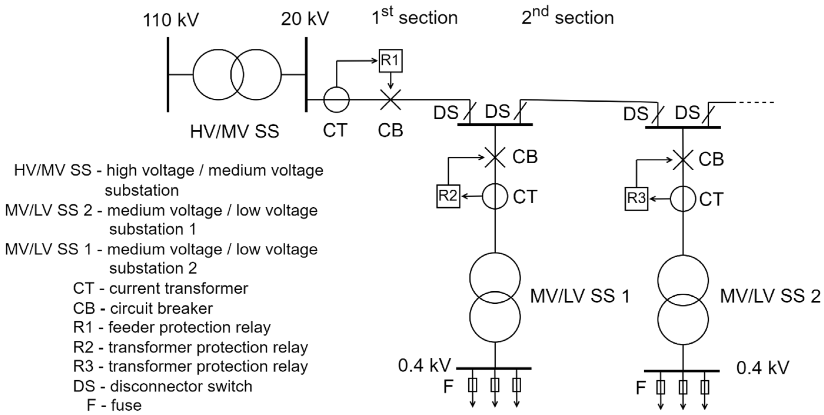
Figure 1, where a feeding substation is delivering power to the distribution network consumers.
Consumers can be connected on a low voltage (LV) network or directly on a medium voltage (MV) network, meaning that in the latter case the MV/LV transformer and the downstream network is a customer’s ownership and maintenance responsibility. However, in both cases the protection philosophy is similar: the feeder’s first line section contains the protection elements (relay denoted as R1 and circuit breaker), which cover all subsequent lines of that feeder. This means that if the short circuit (of any type) occurs, for example on the last line of the feeder, the CT located in the beginning of the first section must detect it and send the information to the relay, which will then initiate the opening of the CB contacts, thereby de-energizing the entire feeder. This situation is actually critical in overcurrent relay protection settings, because it requires that relay R1 must detect the lowest short-circuit current, which is usually associated with 2-phase fault occurring on the end of the feeder. A 2-phase short circuit is lower in magnitude than a 3-phase short-circuit current [
13], according to the well-known relation
. It must be noted that for this relation to be true, inverse network impedance must equal direct impedance, which is usually the case in passive distribution networks. In addition, it is important to note that single phase fault (associated with low or high ohmic earthing of the feeding HV/MV substation) or earth fault (associated with isolated operation of the feeding HV/MV substation) will not be considered in this review paper. The reason is that I
0> protection coordination has a much different philosophy than the multiphase protection due to the specific physical conditions occurring in earth (or single phase) faults, which include zero currents and impedances.
It must also be emphasized that
Figure 1 represents the topology and protection philosophy of a typical European medium voltage distribution network. However, in later references and reviewed papers, authors use topologies and protection philosophies that differ from European practice and in which relays are placed on all MV lines (usually from both sides in tandem with directional overcurrent relays), and the authors’ goal will be to bridge the gap between theoretical and practical observations.
Returning to
Figure 1, it is interesting to point out that the MV feeder cubicle of MV switchboard actually contains CT, relay and CB mechanism, so the term beginning of the feeder is synonymous with the feeder MV cubicle. The feeder relay is usually a definite type OCR, which also contains the instantaneous trip function (I>>). However, the relay protecting the MV/LV transformer is usually an inverse-time OCR, due to the large (5–10 times) magnetizing current flowing through its primary winding when energized without load. The idea is to set the relay to allow the temporary flow of the increased magnetizing current until it subsides, since this is a normal transient operation of the transformer and not a faulty state. Otherwise, unnecessary trips would render the transformer unusable. This applies to all MV/LV power transformers in the network (R2, R3, etc.). Of course, transformers and feeder protection must be selective, that is, in case the fault occurs on LV busbars or the transformer itself, the associate transformer relay must trip first. Only in case of its CT, relay or CB malfunction, the feeder relay must react after a time delay, thereby de-energizing the whole feeder (including all MV/LV transformers).
The above discussion was illustrative of the MV network with radial topology and radial operation. Radial operation is almost universal for MV (and LV) networks. However, MV networks in urban areas can have a loop (or ring) topology, meaning that two (or more) MV feeders from the same HV/MV substation are physically connected with a line that operates in open-circuit mode (on one end the line is opened via switch-disconnector in the MV switchboard of a MV/LV substation). In addition, MV networks in densely populated urban areas can have an interconnected topology, meaning that two (or more) MV feeders from two (or more) separate HV/MV substations are physically connected with a line that operates in open-circuit mode. In this way the security of supply is even greater than in loop topology, since it allows the malfunction of an entire HV/MV substation without affecting electric power delivery to associated loads, because now they can be fed from the remaining HV/MV substation by means of network switching (reconfiguration). Both topologies (loop and interconnected) can change their configuration (and operation) by simply changing the position of normally open-point (NOP), which is of course the switch-disconnector. In practice that means opening the switch-disconnector in an MV switchboard of another MV/LV substation and closing the one that was previously opened. Still, the same protection rules apply for both topologies with one important distinction: the definite-time OCRs are used in networks where the impedance of the network changes very little with the position of normally open-point (NOP), while inverse-time OCRs are used in networks where the impedance of the network changes greatly with the position of normally open-point (NOP).
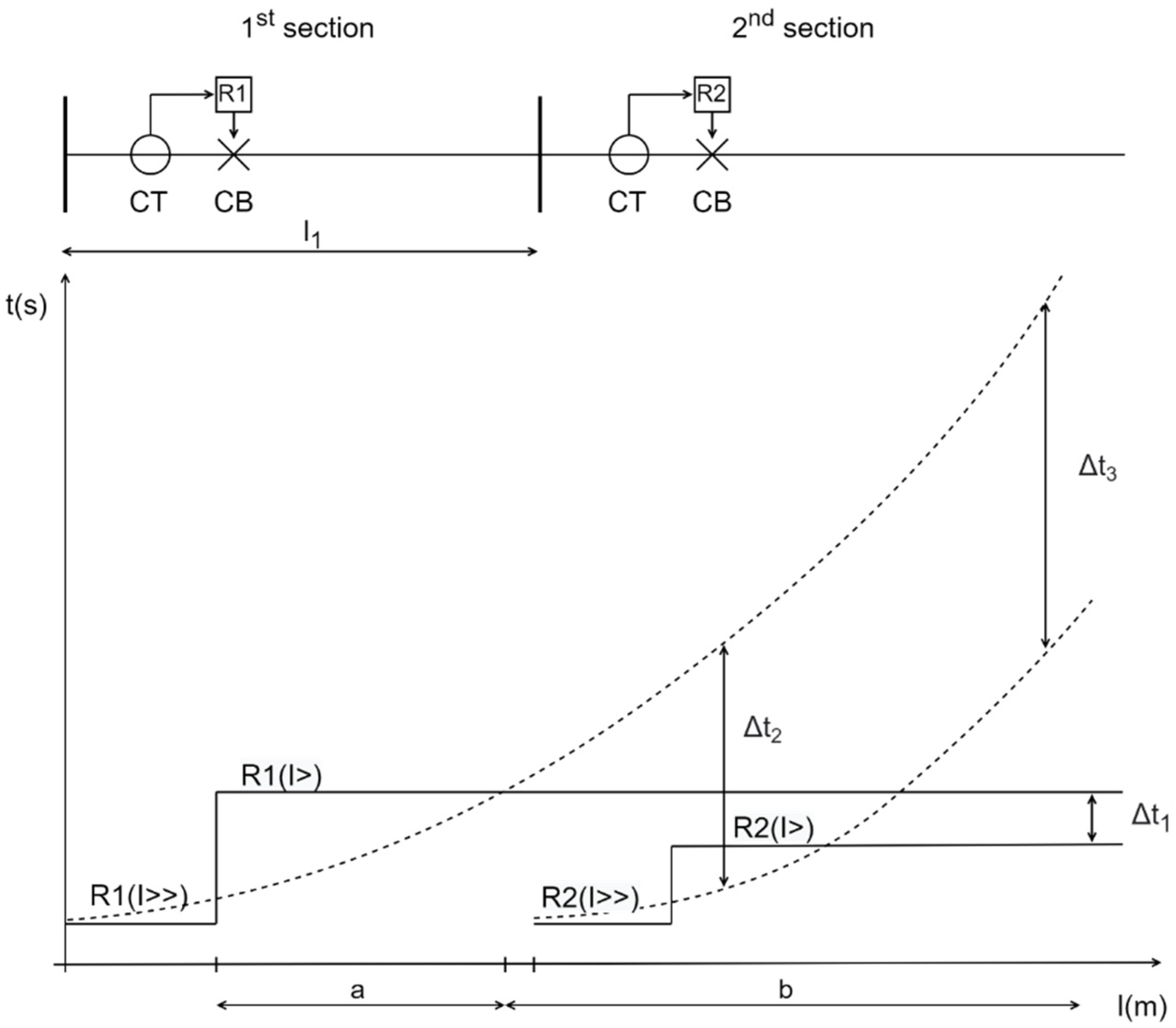
Generally speaking, it can be said that inverse-time OCRs cover the major part of the primary protection zone more efficiently than definite-time OCRs, since they have a faster time response, but it is the opposite for the rest of primary protection zone and a back-up (reserve) protection zone. Both are displayed in
Figure 2, where inverse-time OCR characteristic is displayed with a dotted line and definite-time OCR characteristic is displayed with a continuous line. In area “a” of the relay R1 inverse time beats definite time (it reacts faster), but in area “b” it is the opposite. The same applies for relay R2. It must be noted that area “a” does not have to correspond to the total length of the relay R1 primary protection zone, but in most cases it encompasses its major part.
Additionally, time delay Δt between two relays is uniform and usually lower for two consecutive definite-time OCRs compared to inverse-time OCRs, as is displayed in
Figure 2. This is because in most cases it is much easier to set and maintain a predetermined Δt on a network where definite-time OCRs are used (Δt
1) instead of a network where inverse-time OCRs are used (Δt
2 and Δt
3). The reason for this is that in the latter case operation time is a function of current magnitude, and a protection engineer cannot set the same (uniform) time delay Δt for the entire back-up protection zone. In fact, due to the nature of the inverse function, time delay between two consecutive relays increases with the length of back-up protection zone (Δt
2 < Δt
3). However, when using definite-time OCRs everything involving time delay determination is much simpler. It is very important to note that the time delay Δt between two consecutive relays used in this section is not yet explained in detail. In fact, Δt is an important factor in determining miscoordination between primary and backup relay(s) and is thoroughly explained in
Section 5.2.
Additionally, in this review paper only inverse-time OCRs are observed. This is due to the reason that the OCR optimization cannot be carried out for definite-time OCRs, since their operation time does not depend on the amount of short-circuit current. As is already stated for definite-time OCRs, when the measured short-circuit current overshoots the threshold of the relay, it will send a signal to open the CB contacts irrespective of the amount of that short-circuit current (RMS value). Thus, inverse-time OCRs will simply be termed OCRs in this paper in order to avoid possible future ambiguities.
3. Parameters of an Inverse Type OCR
Overcurrent relays generally have current setting multipliers in the predefined range, which is referred to as plug setting multiplier (PSM). Plug setting multiplier is a ratio between the actual fault current (I
SC) and the calculated pick-up current (I
pick-up).
The pick-up current for each relay is determined by two parameters, the minimum fault current and the maximum load current [
14]. These two parameters will be observed both from a theoretical point of view, which is used in a majority of papers, and a practical point of view, which is used as standard operation procedure (SOP) in European distribution networks.
First, the latter will be described. For example, if a network in
Figure 1 is observed and if it is presumed that the feeder is protected by an inverse-time relay, in order to determine its I
pick-up, first the maximum load current would have to be calculated. To do this, a load flow calculation is necessary (for example, backward-forward iteration method), which in turn will provide information on the maximum load current of the entire feeder (remember that feeder relay R1 protects all the MV lines of that associated feeder). This is usually done in situations where a feeder consists of lines with a uniform cross-section, which in practical cases refers to underground cable networks. Alternatively, the nominal current of the weakest line (branch) can be set as the maximum load current without even performing load flow calculation. This is often done in practical cases where a feeder consists of overhead lines or a mixture of underground cables and overhead lines with different cross-sections. The goal is to single out and protect the weakest line of the feeder. As previously stated, minimum fault current must be determined for sensitivity reasons, because a relay must detect the minimum short-circuit current and differentiate it from maximum load current. Minimum fault current for multiphase faults is calculated usually for 2-phase short circuits, since these fault currents are the lowest, as explained previously.
The place where 2-phase faults need to be calculated is either at the end of the relay primary or reserve protection zone, each multiplied with its own correction factor. The correction factor for the end of primary zone is 1.5 and for the end of reserve protection zone it is 1.2. In case of
Figure 1, the relay R1 primary protection zone goes to the end of the feeder (last line). Its associated reserve protection zone covers the protection of the next downstream relay(s), in case of malfunction. In this particular instance, the reserve protection zone consists of relays R2, R3, and others that have the task to protect MV/LV transformers. Thus, a 2-phase fault needs to be calculated on LV busbars of all associated MV/LV substations and the lowest 2-phase short-circuit current (in most cases also at the end MV/LV substation of the feeder) is singled out as the candidate for relay setting. In almost all cases in distribution networks, 2-phase faults have the lowest value at the end of the relay reserve protection zone, not primary zone. Thus, I
SCmin for
Figure 1 will usually be calculated at LV busbars of the last MV/LV substation of the feeder.
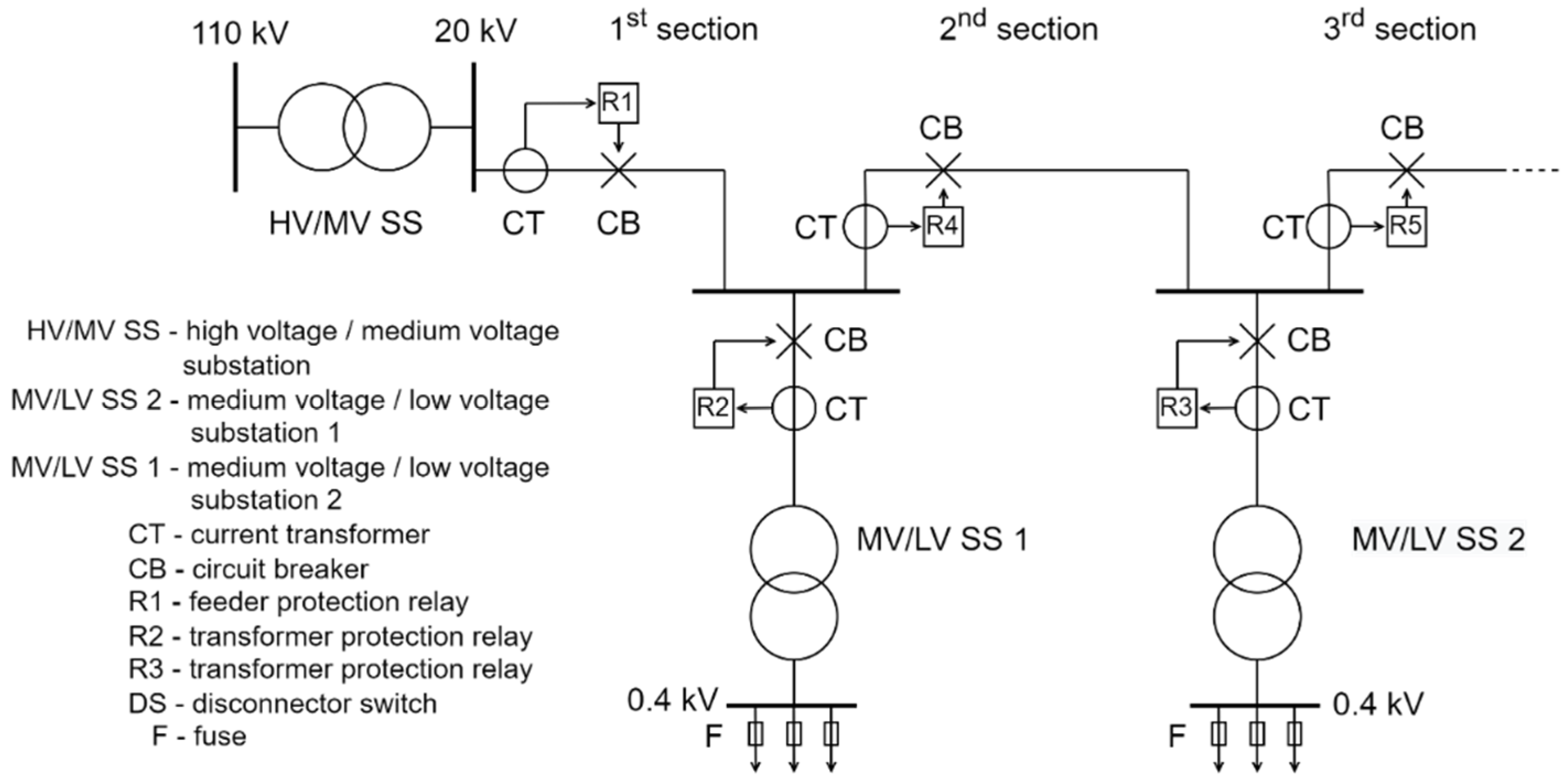
The aforementioned statements are valid for European MV networks. However, in most articles and research papers another topology and protection philosophy of the distribution network is used, although the principles are almost equal. In
Figure 3 a radial distribution feeder is displayed that contains protection relays for each line.
Unlike the European practice, in which the 1st feeder relay’s primary zone covers all the lines, here each line section is protected with its own associated relay and CB. If it is presumed that only inverse-time relays are used, in order to determine Ipick-up of the 1st line section the maximum load current of that line would have to be calculated. To do this, a load flow calculation is necessary (for example, backward-forward iteration method), but with a difference that only the information on the maximum load current of the 1st line will be used. This time the alternative of using the nominal current of the 1st section (branch) by inspecting the line’s design documentation cannot be used, because there is no guarantee that the 1st section is the weakest line of the feeder. Actually, it is quite the opposite, since higher cross-sections are used near the feeder beginning. In other words, determining the Ipick-up for the 1st line with the information on its nominal current would lead to a situation in which the relay R1, for example, would not detect an overload occurring on the 2nd line, in case that line has a lower nominal current. That would, of course, negate the fundamentals of network protection philosophy since the upstream relays must detect overload/fault current of all downstream relays (albeit their output signal towards their associated CBs will be time-delayed in case a downstream relay or CB malfunctions). The same applies for all feeder lines, meaning that only the information on maximum power flows of those lines is necessary in order to set Ipick-up of their associated relays, and not the nominal currents found in lines’ design documentation.
As previously stated, in order to properly set I
pick-up, minimum fault current must also be calculated for sensitivity reasons. The place where 2-phase faults need to be calculated is either at the end of the relay primary or reserve protection zone, each multiplied with its own correction factor. In case of
Figure 3, the relay R1 primary protection zone covers only the 1st line section, as is similar for primary zones of all the relays that protect lines (R4, R5, etc.). Its associated reserve protection zone covers the protection of the next downstream relay(s), in case of malfunction. In this instance, the reserve protection zone of relay R1 consists of transformer relay R2 and line relay R4. Thus, a 2-phase fault needs to be calculated on the LV busbars of the associated MV/LV substation 1 and at the end of the 2nd line section. The lower of those 2-phase currents will be used to set I
pick-up of relay R1, since it has to detect the smallest short-circuit current in its reserve zone of protection. In most research papers, a 2-phase fault is calculated at the end of the next downstream line, while a MV/LV transformer (along with its secondary LV busbars) is usually neglected. That also will be the case in this review paper and the subsequent figures will not contain transformers.
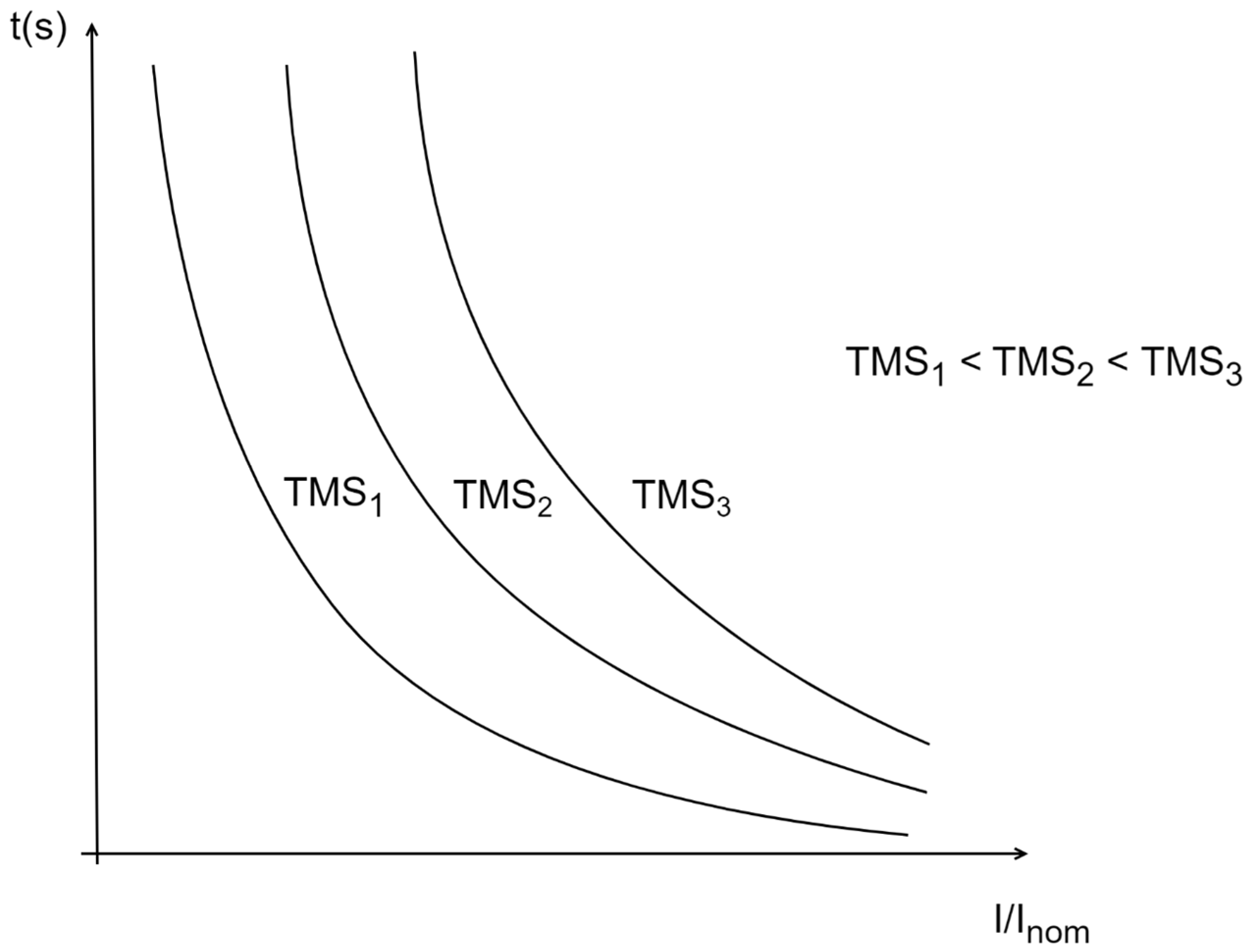
Time Multiplier Setting (TMS) is another parameter used to change the value of operation of the relay. If this value is higher, the relay will take more time to operate and vice versa. This is displayed in
Figure 4. TMS is used in Equation (3), which will be described in
Section 5.
4. Previous Research on OCR Operation Optimization Techniques
Each protective relay must coordinate with other protective relays located on all adjacent buses. Their coordination is an important factor in the design of the protection system. With the protection coordination, the primary relay trips as fast as possible for its zone of protection and operates with a delay to be a backup for downstream protective devices [
15]. In the coordination optimization problem of overcurrent relays, which is the subject of this paper, the objective is to determine the time multiplier setting (TMS) and the plug setting multiplier (PSM) of each relay so that the total operating time of the primary relays is properly minimized, while at the same time avoiding (or also minimizing) the number of relay miscoordinations. This will be described mathematically in
Section 5 with Equations (2)–(6). Miscoordination between two consecutive relays occurs when both relays detect a short-circuit current, but the upstream relay reacts in tandem with (or sometimes faster than) the relay closest to the fault, thereby de-energizing its healthy line together with the faulty line of a downstream relay. For example, if the relay R4 in
Figure 3 would react faster than relay R5 in case of a fault on the 3rd line, both 2nd line, 2nd transformer (and its associated LV consumers), 3rd line and so on would be de-energized. However, if the coordination was proper, in case of a fault on the 3rd line, both 2nd line, 2nd transformer and its associated LV consumers would remain operational. The miscoordination conditions involve a term called “coordination time interval” (CTI) and this will be explained in detail in
Section 5.2.
In addition to TSM and PSM, the optimum method, objective function (OF), network topology and the nonlinear relay characteristics proportional to TSM and PSM are important aspects for optimum coordination [
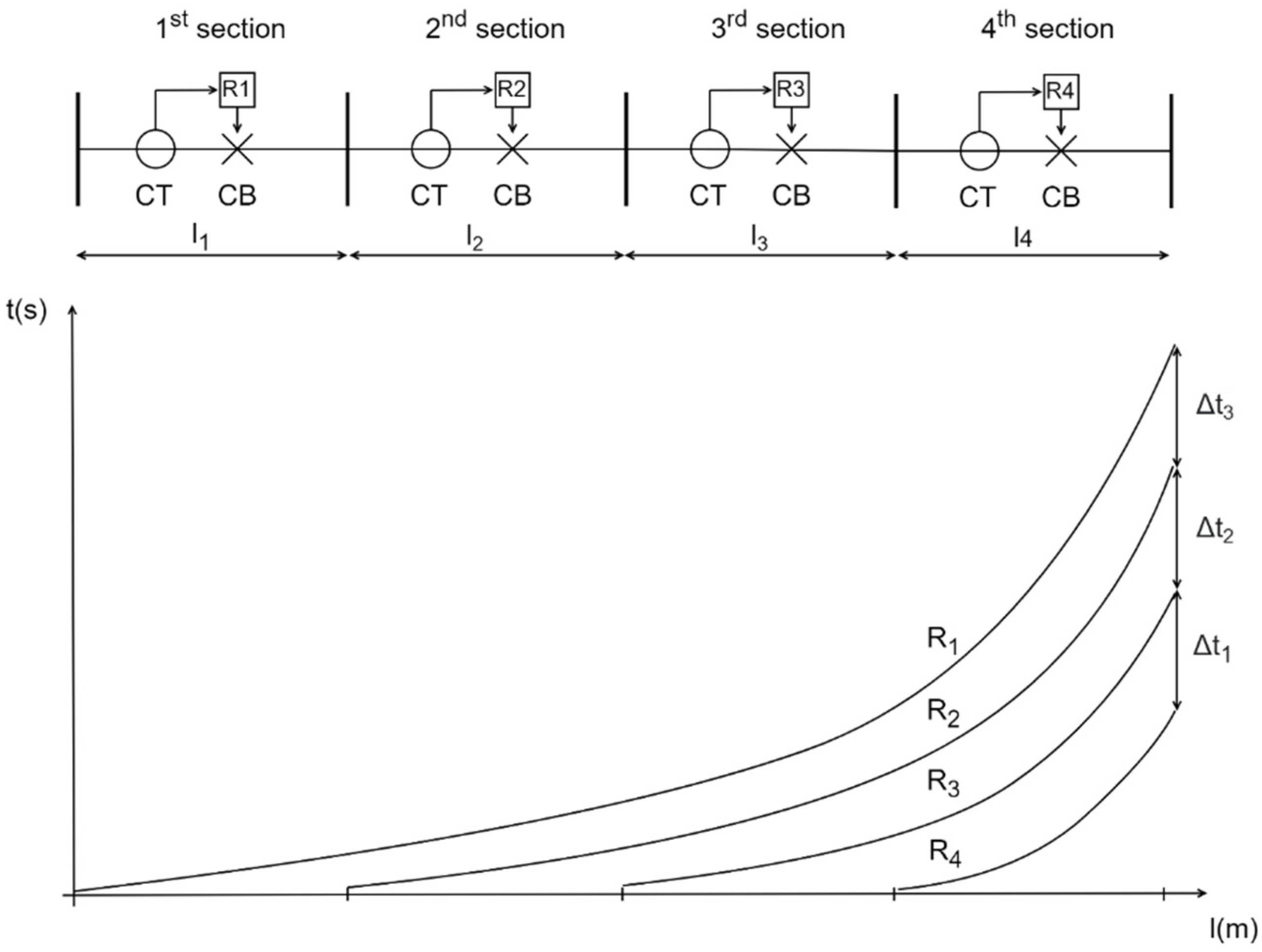
15]. An example of a proper inverse-time OCR operation optimization for a radial distribution network is displayed in
Figure 5.
In this particular example it can be clearly observed that all the lines have a backup protection (even the first line, but its backup protection is an upstream relay on the secondary side of a HV/MV transformer that is not displayed in
Figure 5) and it is graded beginning from the last line up to the first line. Thus, the last line has a triple back-up protection, meaning that the relays R3, R2 and R1 must be set to detect a 2-phase short-circuit current at the end of the last feeder line, albeit it must be emphasized that the total time delay rises respectively by Δt
1, Δt
1 + Δt
2 and Δt
1 + Δt
2 + Δt
3.
It is also important to repeat again that in practical MV network cases only the protection at the beginning of the feeder is installed, unlike in most optimization problems, where it is presumed that each line has a protection relay device associated with its circuit breaker. This is due to the reason that in the past, when distribution networks were exclusively passive in operation, using the latter solution proved costly and it was not affordable for a Distribution Network Operator (DNO). In other words, losing an entire MV feeder (which in practice fed a village or a relatively small part of a town) was a lesser problem than losing an HV feeder, which carried a significant amount of power (approx. 10–20 times more than a distribution feeder) and the loss of which could lead to a blackout situation of a much larger portion of customers (entire towns or parts of cities), or in a worst-case scenario it could lead to unstable operation of the part or even the whole power system (in case of a cascade failure).
Moreover, using more relays in the MV network would create a problem of selectivity between the neighboring relays. This is because electromechanical relays (which were used before) had a relatively long time delay (approx. 0.5 s) and it was hard to time grade more consecutive relays in one feeder without avoiding a longer trip time of backup relays. Longer trip time of backup relays is not a problem per se, but the protected elements (lines, transformers and so on) were exposed to short-circuit currents longer, which could potentially destroy them or deteriorate their parameters. By the introduction of numerical relays this problem was solved because time delay could be set to much smaller values (approx. 0.3 s). Additionally, in modern active distribution networks with bi-directional power flows and a raised awareness of power system quality and security of supply (addressed through SAIFI, SAIDI, CAIDI, ENS, and other indices) the problem of installing additional OCRs and CBs “in depth” of the medium-voltage network is even more accentuated, and so in this (and the subsequent) paper the optimization problem will be reviewed from both a theoretical and contemporary practical point of view.
Various approaches to the optimum coordination of OCRs used to protect distribution systems have been proposed in the literature. Early studies proposed conventional methods such as trial-and-error and the topological analysis method [
16]. Due to the complexity of the system, these approaches suffered from the need for a large number of iterations and a slow convergence rate, which resulted in them becoming time consuming and non-optimal.
Later, new approaches such as optimization methods with linear programming (LP) [
17,
18,
19] and nonlinear programming (NLP) [
20,
21] were proposed to solve the coordination problems of overcurrent protection. NLP optimization methods offered better performances than the methods of LP in solving the OCR coordination problem. However, the convergence rate of such optimization algorithms was still slow as the system size increased [
22].
Recently, nature-inspired algorithms and artificial intelligence-based algorithms have been widely used because they achieve the same task in a relatively short time and lead to near-to global minimum coordination (albeit they cannot guarantee the finding of a global optimum solution). These include Firefly algorithm [
23], Particle Swarm Optimization (PSO) [
24,
25], Ant Colony Optimization [
26], Evolutionary programming [
27], Gray-wolf optimizer [
28], Fuzzy logic [
29], Learning based optimization [
30], hybrid approaches [
31,
32,
33,
34,
35] and Genetic algorithm [
5,
32,
36,
37,
38,
39].
The genetic algorithm (GA) is a randomized optimization and search technique guided by the principle of natural genetic systems. It is one of the most robust tools for solving various optimization problems and has a wide range of applications in distribution power networks, for example, optimum capacitor allocation, optimum distributed generation (DG) allocation, optimum Battery Energy Storage System (BESS) allocation, optimum distribution network reconfiguration and others. The authors will lay out a proposed theory based on GA structure for OCR operation optimization in a sequel of this review article.
The aforementioned optimization techniques have superior performance in terms of achieving the near-to global optimum compared to the traditional brute-force search, trial-and-error, topological and conventional LP and NLP algorithms. However, most evolutionary and heuristic algorithms require more computational time and also suffer from premature convergence, actually proving the “no free lunch” theorem. To date, a significant effort has been made by researchers to solve the optimum relay coordination problems of OCRs. In most of the cases, the main focus is on optimizing the relay settings so that the total relay operation time can be minimized.
Many approaches are based on OCR optimization in meshed distribution networks, although this particular operation is seldom used in European practice. Mesh operation mandates the usage of directional relays on the end nodes of protected elements (lines), thus magnifying the complexity of this problem [
40,
41,
42,
43,
44,
45,
46]. Proper solutions comply with the desired protection philosophy where relays react in minimum time from both sides of the protected element and thereby enable continuous delivery of electrical power to all consumers of the network.
A very recent approach to OCR optimization is the inclusion of adaptive protection of distribution networks. However, this concept relies heavily on the extensive and reliable communication infrastructure and a central automation system. The latter may be incorporated into an existing SCADA distribution management system (DMS). The goal is to minimize relays’ operating time throughout the network on the basis of correct state estimation of network topology [
47,
48,
49]. Distribution network topology is not constant in time, and changes occur in the network that result in different configurations. The reasons are usually faulty states, planned maintenance or even switching for loss minimization purposes. This simply means that, according to the changing network configuration, protective relays will not be manually readjusted, but instead their settings will be dynamically updated.
Implementation of the aforementioned protection philosophy still encounters many challenges, primarily due to the fact that extensive communication infrastructure requires significant costs for the DNO. Although HV/MV substations are mostly incorporated in SCADA/DMS, small MV/LV substations are only partially incorporated into the latter system. Secondly, minimization of inverse-time OCRs is often accompanied with combinatorial explosion, since relay parameters are volatile in time, meaning that each relay has n TMS and PSM parameters corresponding to n respective network configurations. Adaptive protection of distribution networks can be achieved without significant obstacles if definite-time OCRs are used. However, as stated, definite-time relays cannot be included in the optimization problem since using them nullifies Equation (3) in the subsequent section, which is central for the optimization problem.
5. Basic Problem Formulation and Statement
Power system protection is usually implemented as primary and backup protection. Accurate identification of relay requirements and proper coordination among protection relays are the most important tasks to ensure reliable and safe operation of the power system. Reliable coordination of OCRs means that the primary relay should isolate faults in its own zone quickly, and the backup relay should operate after a certain time Δt to clear the fault without delay if the primary relay does not operate (experiences a malfunction).
The OCR coordination problem can be formulated as a constrained optimization problem. Therefore, the main aim is to minimize the total operating time of all relays present in the system. Objective function used in most of the literature is given in Equation (2):
where
is the number of relays,
is the operating time of relay
and
is the weight assigned to each relay representing its operating time. If all relays are equally important (meaning they protect equally sensitive load), the term
may be omitted.
5.1. Defining OCR’s Inverse Time—Current Characteristic
A nonlinear inverse OCR characteristic function that has been reported in most of the literature [
50,
51] is shown in Equation (3):
where
,
,
are constants chosen to provide the selected curve characteristics,
is the actual fault current flowing through the relay coil,
(Plug Setting) is the relay current set point and
is the Time Multiplier Setting of the relay
. The values of
,
,
are given in
Table 1 [
36,
37].
and
from Equation (1) are actually synonyms, and
is a synonym to
.
The operating time of the relay is affected by the upper and lower limits of its settings
and
, respectively. Therefore,
and
are the most important variables to be optimized for the coordination problem.
adjusts the time passed between the moment the relay detects the fault current and the moment it sends the signal towards the CB to open its contacts. This, of course, occurs when the fault current reaches a value equal to, or greater than, the current threshold set by
.
limitation is specified so that the minimum pick-up current setting is selected to be greater than the maximum load current for each relay covering the protected element (for example, line). Also, the maximum pick-up current setting must be selected to be less than the minimum 2-phase fault current on the end of the protected element (for example, line) [
52]. Both minimum and maximum pick-up currents are described in
Section 3 and in practice only a single value,
, is used for setting the relay. The general equation for determining
can be stated as:
where
(0.9–0.95) denotes ratio of return current (maximum value of current at which the relay releases its contacts when the current decreases) and operating current (current at which the relay closes its contacts when the current increases),
(1.2–1.4) denotes safety factor which is introduced so that the relay does not start to operate in case it detects maximum load current
and
is sensitivity coefficient (1.2–1.5), which is introduced so that the relay recognizes the minimum 2-phase fault current
at the end of its primary or reserve zone (usually the latter). In practical cases
is actually set closer to the left side of the equation because it is better to indiscriminately trip the slightly overloaded line than to trip only for minimum fault currents. In this “gray area” between maximum operating current and minimum fault current it is always best to “sacrifice” sensitivity for safety, that is, it is better to mistakenly de-energize a feeder than to allow long-term overcurrent flow and the consequential destruction or deterioration of its element (for example, branch). This is of course characteristic for distribution networks, whereas for transmission networks the continuous operation of the system is almost essential, so apart from introducing distance relays there are additional tools with which a transmission network operator can accurately assess the overload state of its elements (dynamic thermal rating, DTR). Returning to the distribution networks, it is also important to point out that if safety was “sacrificed” for sensitivity, another problem would arise due to the fact they are radially operated. Every subsequent repair or replacement time of an affected element (for example, branch) would ultimately result in a much higher ENS (Energy Non-Supplied) and other reliability indices for the system, thus proving that it is better to stay on the safe side of the previous equation.
5.2. Coordination Constraint
The coordination constraint between the main and backup relay can be expressed as follows [
53,
54,
55]:
where
and
are the operating time of the backup relay and the primary relay, respectively.
is the abbreviation of “coordination time interval”. Roughly speaking,
mostly consists of CB operating time, which is measured from the moment the CB received a trip signal from the relay until the moment its contacts are opened (and the current stops flowing through the CB).
also consists of its associated relay’s over-travel time (characteristic only for electromechanical relays) and relay tolerances and setting errors. This is the reason why a total
is higher for electromechanical relays (0.5 s) than for numerical relays (0.3), which do not have moving parts.
The question is why should a minimum time period of pass between the operation of a backup relay, in case a primary relay fails to operate, even if their respective time–current inverse curves are not mutually intersected? The reason is that a situation where both relays send a trip signal to their associated CBs may occur. For example, if both primary and backup relay detect a short circuit, they will both be activated. However, the primary relay, which is closer to the fault, must generate its output trip signal for its associated CB after ms, while the backup relay will wait until its internal clock counts the time . Now the primary relay has sent the signal to its CB and CB must open its contacts in time. This cannot be as fast as a relay operation (because numerical relay can operate, that is, perform its internal script and generate a trip signal in approx. 30 ms), and due to CB’s mechanical lever operation and arc quenching time, will last for 0.3 s (it is presumed that CB works in tandem with a numerical relay). If during that time backup relay’s internal clock counts the time , it will generate a trip signal (in 30 ms) and send it to its associated CB. This happens because the primary relay’s CB has not fully opened its contacts ( time has not lapsed) and the fault current is still flowing through both CTs and both relays can detect it. Thus, both CBs will operate and both protected elements (for example, lines) will be de-energized as a result. For this reason alone, it is essential to allow a minimum time to pass between primary and backup relay operation.
The coordination constraint can be rewritten in terms of discrimination time as follows [
56]:
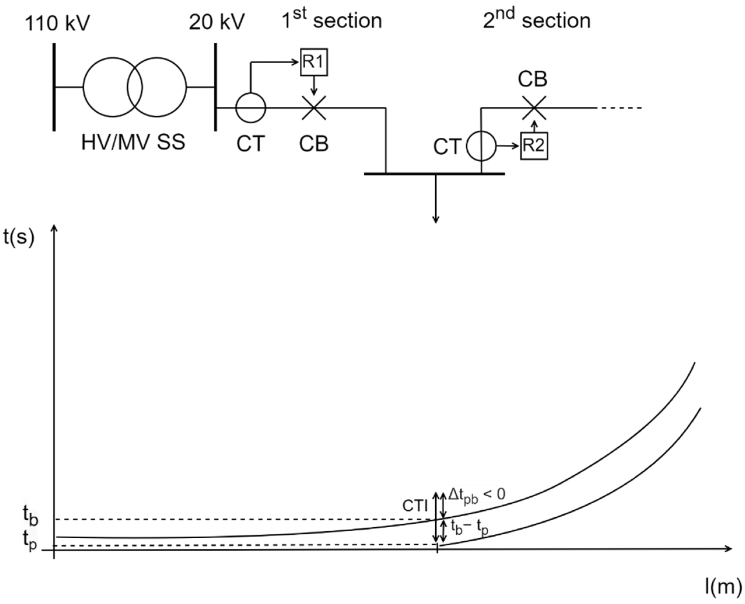
where
represents discrimination time. In case of a negative value of
miscoordination occurs, leading to an infeasible solution of the coordination problem, because this means that both relays send a trip signal to their associated CBs. However, this constraint can be included in the objective function, but with the emphasis that it must be penalized (as will be explained in detail in the next article where complex objective functions will be observed and reviewed). The aforementioned situation is displayed in
Figure 6 where
is predefined as 0.3 s.
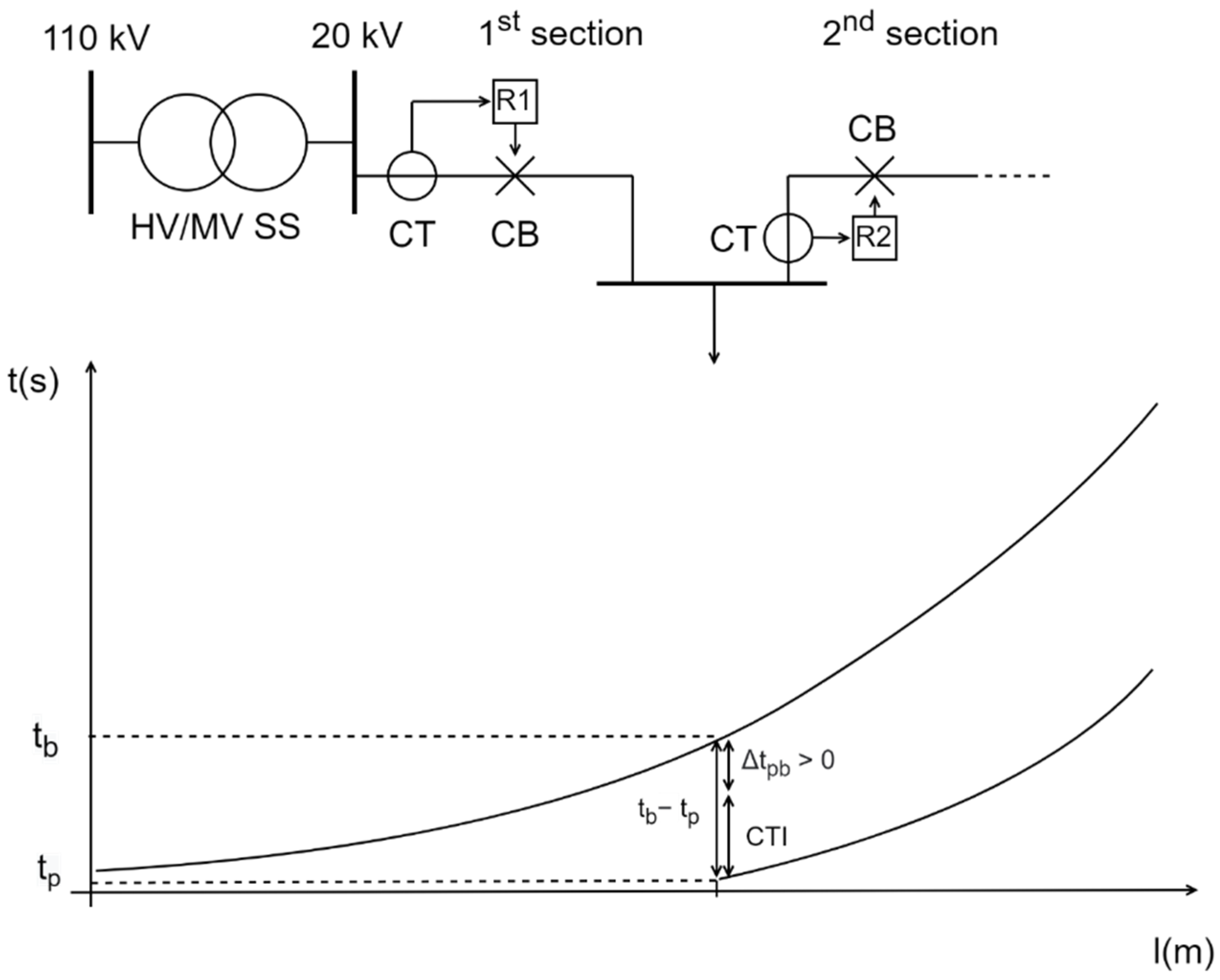
Similarly, in case of a positive value of
, the problem solution becomes feasible because miscoordination will not occur between a primary and backup relay. In addition, this (satisfactory) constraint can be included in the objective function if the protection engineer’s goal is to additionally minimize the (positive) discrimination time
while at the same time preserving predefined
. The situation with a proper coordination between two consecutive relays is displayed in
Figure 7 where
is also predefined as 0.3 s.
A potential problem when including discrimination time
in the objective function arises from the fact that this parameter needs to be modified in order to include it in the objective function denoted by Equation (2). By not changing it, a negative discrimination time would actually improve the results, which is of course inadmissible. Many authors have invested significant effort in minimizing the discrimination time, while at the same time avoiding possible miscoordination between primary and backup relay pairs [
39,
41,
42]. Even when minimized, this parameter alone cannot guarantee that the primary relay operating time
will not last longer than allowed, according to the equation for thermal equivalent short-circuit current. Worse still is the situation where the primary relay fails to operate, and a slower reaction time of a backup relay
causes damage to the protected element. The aforementioned problem will be addressed in the following subsection.
5.3. Bounds on Operating Time of a Relay
To maintain reliability and ensure proper timing response, a relay requires a minimum time to start the tripping mechanism of its corresponding circuit breaker, but it is not desirable for it to require a long time to be activated when needed:
where
and
are the minimum and maximum operating time of relay
, respectively. These relay operating time limits are defined in accordance with the requirements of the protective schemes [
57]. Term
usually denotes the time associated to generate a relay’s trip signal for CB and in numerical relays this takes approx. 30 ms. In other words, the relay’s fastest operating time is 30 ms, and it cannot react faster than that. Term
is somewhat of an ambiguity. Although in most review papers this limit is predetermined, it is never fully explained.
It is the opinion of the authors that
should be removed from the Equation (7) and that it should be separately inspected for different cases of fault currents, as will be explained below. In fact, it should be associated with the operating time calculated for different types of short circuit at the beginning and the end of the protected element (for example, line). This is to ensure that a fault current flowing through the protected element (for example, line) for a time period until the relay operates, will not over-exceed design documentation specification data. In case it does, its mechanical or electrical parameters will deteriorate or the element may become damaged (for example, the insulation of the cable will melt). The reason the authors propose the inspection of
for different faults at the beginning and the end of protected elements is that even a low
can be a cause for damaging an element if the short-circuit current flowing through the element is high enough. These data are actually available in the design documentation and can be found in the following general equation:
where
is the actual short-circuit current flowing through the element,
is the relay operating time, and
is called the thermal equivalent short-circuit current and it can be found in the electrical design documentation of cables and overhead lines (OHLs). The latter term denotes the RMS value of a current having the same thermal effect and the same duration as the actual short-circuit current, which may contain a DC component subsiding in time. Whether a short-circuit waveform will contain a DC component or not depends on the value of voltage at the generators’ terminals at the moment of short-circuit occurrence.
Since the elements of the distribution networks are located far from large generators (sources) connected to the transmission networks and there is a large impedance between them (R/X ratio is high), this decaying DC component can last for a very short time. This occurs because the transient time constant of the short circuit (
) is much shorter than in transmission networks, exactly due to a high R/X ratio. Thermal equivalent short-circuit current is essential for a proper rating of power conductors and equipment (lines, busbars, and so on), with special emphasis on an element’s cross-section calculation and determination. If the actual short-circuit current flowing through the element is greater than
, the generated heat
will start to melt the copper or aluminum wires, thereby deteriorating its mechanical and electrical parameters. When used in transmission networks, Equation (8) will be written differently and term
will be substituted by
, which denotes the calculated thermal equivalent short-circuit current for the protected element (branch, busbar, and so on). This calculation is often simplified by using the following equation:
where
and
are factors explained in [
58]. Equation (9) is used when a fault occurs in transmission networks and a short-circuit current consists of a decaying DC component. However, as stated, in distribution networks this is often not the case due to high R/X ratio and, although a fault current may also contain a subsiding DC component, the
and
factors in Equation (9) can be approximated as 0 and 1, respectively, without much loss of accuracy. Thus, a following simplification can be made where
. Now Equation (8) can be used for distribution networks without a need to calculate thermal equivalent short-circuit current for each element according to Equation (9).
As said, the relay operating time factor in Equation (8) is also of a concern for the optimization problem. When using definite-time relays, Equation (8) is relatively easy to solve, since their operation time is the same for all currents exceeding the predetermined threshold value. In the same equation, it is enough to determine the worst-case scenario fault, which is usually calculating the 3-phase short-circuit current at the beginning of the protected element (for example, line) and verifying if that amount of current is lower than the factor represented by the righthand side of Equation (8), in case a definite-time OCR clears the fault in time. If the clearing time of a definite-time OCR is set to 1 s, then it is enough to check if the 3-phase short-circuit current at the beginning of the element is lower than the thermal equivalent short-circuit current rated in the design documentation data.
However, when using inverse-time relays, the situation is not so simple. Here the relay operation time is a function of current magnitude, so more cases must be examined because an element may become damaged due to different faults, each associated with its unique operating time (according to the inverse time–current characteristic). Relay operation time must be calculated for each case using Equation (3). The first case is the same as with definite-time OCRs, and it involves checking maximum 3-phase short-circuit current at the beginning of the protected element, since in that situation it is certain that relay operation time will be the shortest. By calculating maximum 3-phase short-circuit current and relay operation time from Equation (3) it is easy to verify Equation (8). The same principle applies for all other cases. The second case is calculating the 2-phase short-circuit current at the beginning of the protected element, since in that case the relay operating time will be longer. The last two cases involve calculating a 3-phase and 2-phase fault at the end of the protected element. The potential problem is that 3-phase short-circuit current at the end of the element is of course lower than the one at its beginning, but the relay operation time is now slower, and this combination can lead to exceeding thermal equivalent short-circuit current. Lastly, 2-phase short-circuit current at the end of the element is the last extreme case, where the lowest multiphase short-circuit current will cause the OCR to operate slowest, meaning that a danger of breaching still exists. This is because the denominator on the right hand side of Equation (8) will have a higher value, thereby artificially lowering the thermal equivalent short-circuit current. When all these cases are calculated for an element and if there is even one case in which Equation (8) is breached, the optimization solution should be deemed infeasible and must be completely removed from the optimization process, since it can result in a serious damage to the protected element.
As a consequence, the upper term in Equation (7) must be redefined, should be omitted and different operating times associated with different fault currents should be calculated for an element during the optimization process. This should be done for each proposed solution (relay and setting), and in case there is a single element where Equation (8) is breached it must be exempted from the optimization process.
5.4. Bounds on Time Multiplier Settings
The
limitation [
59,
60] is expressed in Equation (10) where
represents the minimum
value of the relay
, and
represents the maximum
value of the relay
:
In practice, the values of
vary between 0.05–1.2 [
61].
5.5. Bounds on Plug Settings of a Relay
Constraint considering the pickup current setting is given in Equation (11), where
and
are the lowest and highest values of
for the relay
, respectively [
62].
The values of
setting depend on the actual conditions in network, as was already discussed in
Section 3. The minimum pick-up current setting
is usually set to be equal or greater than 1.2 times the maximum load current. That is because sensitivity is often overlooked in favor of safety. Similarly, maximum pick-up current setting
is set to be less than or equal to 2/3 of the maximum fault current [
32]. Authors would propose, according to
Section 3, that
should be equal to the lowest value of calculated 2-phase faults at the end of the relay primary or reserve protection zone, each multiplied with its own correction factor.
6. Optimum OCR Coordination Process
As the basis of electric power system analyses, short-circuit current calculation is an important step for setting correct inputs for protective devices. Once the network is modelled with the desired electrical parameters of the elements, it is very important to determine the maximum short-circuit current under fault conditions for each node and with that information perform the relay coordination. The operating time for each relay is determined using Equation (3). It is worthy to emphasize that, when calculating , short-circuit current that must be calculated beforehand is actually associated only with the primary protection zone.
The next question is what multiphase fault current must be used while calculating the central optimization function described with Equations (2) and (3) and where should its occurrence be? In most of the research articles the type of fault and its position along the line is not clearly specified, but the authors will propose that only maximum 3-phase fault currents should be observed. To explain this choice for Equations (2) and (3) an opposite situation will be demonstrated; in Equation (3) only 3-phase (or even 2-phase) fault current at the end of the line will be included. Since this current is lower than the one at the beginning of the line, of the associated relay will be greater, meaning that now the optimization goal is minimizing the operating time of relays reacting to faults at the end of their respective lines. Since the operating time for multiphase faults at the end of the line is greater than at the beginning (due to the inverse nature of I-t function), one important piece of information regarding the coordination between primary and backup relay will be hidden from the protection engineer.
As can be seen from
Figure 2, the time delay Δt between any primary and backup relay increases with line length, so it can be stated that for relay coordination the most critical part where a fault may occur is at the beginning of the line. In other words, if the actual time delay Δt between two consecutive relays is lower than a predetermined threshold (for example 0.3 s) then the backup relay will trip along with the primary relay on a faulted line, thereby de-energizing both the faulted and healthy line. If a protection engineer has at his disposal only information on Δt between primary and backup relay for a fault at the end of the line, he does not know if those relays will mis-coordinate for a 3-phase fault at the beginning of the line. In fact, according to
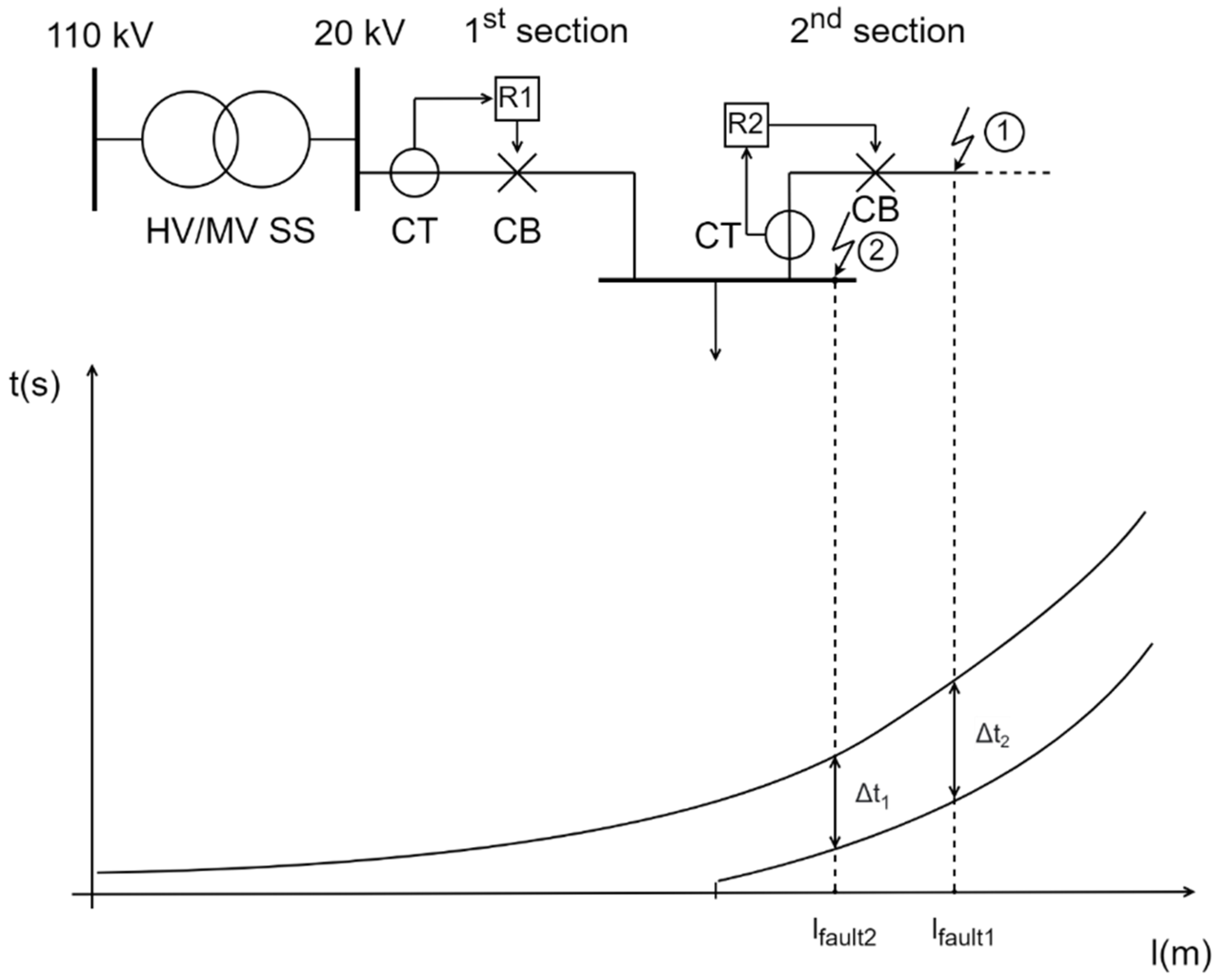
Figure 2, the value Δt between primary and backup relay for a fault at the end of the line is actually the highest value of Δt function along the line, and the authors’ opinion is that Δt should be examined for the most critical situation, which is the highest fault (3-phase short circuit) at the beginning of the line. The last factor regarding this choice is also worth mentioning, and it concerns the actual place where 3-phase fault will be calculated, which is shown for relay R2 in
Figure 8. Please note that the measure of the l-axis is exaggerated compared to the practical cases in order to differentiate the terms displayed below.
Although the most correct place to calculate this current is just after the circuit breaker (fault 1), the authors will calculate this fault at the busbars located at the beginning of the line (fault 2). The results will differ very little from the first case (since this difference in practice is only a few meters of cable/overhead line), as is displayed in
Figure 8, and this way the calculated current will be slightly larger, meaning the results will stay on the safety margin. If by this presumption Δt
1 at busbars’ fault (fault 2) is bigger than
between relay R2 and backup relay R1, it can be safely stated that in case of a fault after CB (fault 1) the latter will remain true for Δt
2. The opposite will, however, result in discarding both relay settings by the protection engineer. Why? Because if Δt
1 at busbars’ fault (fault 2) is lower than
, there is still a possibility that in case of a fault after CB (fault 1) Δt
2 will be greater than
. However, since this rise of Δt along the line or the difference between Δt
2 and
is very small in absolute values (in milli or microseconds), this solution will be discarded for safety reasons. Summarily, the actual place for 3-phase fault calculation will be at the busbars located before the associated relay and this will be true for all relays in the proposed optimization algorithm, which will be covered in a future article.
When optimizing OCR operation, additional concern must be placed on possible problems regarding DG impact on protection coordination. Sympathetic tripping and protection blinding are the two most common examples of relay false triggering. The first concerns the situation in which a DG on one feeder supplies short-circuit current to another feeder where the fault occurred. Both upstream and DG contributing currents now flow through the affected feeder, thereby lowering the associated relay’s operating time. The gravest problem here lies in the fact that breaking and making capacity of CBs and electrical equipment, through which this increased fault current flows, may become breached.
Protection blinding is characteristic for relays between the upstream network and a DG unit, in case of a fault downstream of that DG unit. Since upstream network contributing current is determined by network and DG impedance, its amount may become lower compared to the case where no DG is connected. This simply means that the mentioned relays will not detect a short-circuit current occurring on the lines beyond that DG unit.
It can be concluded that whenever a new element is added in a distribution network and whenever its configuration is changed, the protection parameters need to be carefully examined, reviewed and updated.
7. Conclusions and Future Research
In this paper the authors have thoroughly addressed the concept of overcurrent relay operation optimization and its fundamental terms and tasks. First, the difference between definite-time and inverse-time OCRs has been highlighted and their most important pros and cons were stated. In addition, the circumstances in which using each type of relay is the most appropriate were pointed out. Next, the standard parameters of inverse-type OCRs were described and it was stated that the relay’s sensitivity limit should be determined for 2-phase short-circuit currents at the end of the reserve protection zone. However, maximum load current should be the most important factor for plug settings multiplier determination due to the specific operation requirements for distribution networks. The latter statements were compared from both a theoretical and practical point of view. Next, the basic OCR optimization problem formulation was reviewed and a systematic approach based on previous research was carried out. A very important term to explain was the coordination time interval and its influence on the solution of the optimization problem. Moreover, the upper bound of the relay operating time was critically examined and an alternative was proposed, which has a very distinct usage in practice. Finally, the optimum OCR coordination process was reviewed and it was proposed that a 3-phase short circuit at the beginning of the protected element’s primary zone should be used to calculate the relay operating time for the optimization function. This was accentuated in order to dismiss the possible breach-of-coordination time interval between two relays that would occur when calculating other types of short-circuit faults along the protected element (usually line).
The importance of this paper was to critically examine the fundamentals of the OCR optimization problem and to clear possible ambiguities regarding its implementation in practical cases. Special attention and effort was put into validating the parameters and constraints of a basic OCR optimization function, which will serve as a basis for future research. The authors plan to follow up on this review paper with another one, which will deal with advanced objective functions, their advantages and drawbacks, and its goal will be to propose a new method for optimum overcurrent relays’ operation. Topics such as distributed generation protection, directional relay usage, meshed network operation and the gradual automation of distribution networks “in depth” will be separately observed, systematically analyzed and integrated into a proposed new approach for defining and handling the OCR optimization problem.
Additionally, an effort will be made to align different types of protection functions in a single optimization problem. By integrating definite- and inverse-time OCR protection and by adding differential and under/over voltage protection, the quality of solutions would be greatly upgraded and the objective function would more precisely mirror the actual practice in DNOs’ networks.


