
Design and Implementation of the Bidirectional DC-DC Converter with Rapid Energy Conversion


Abstract
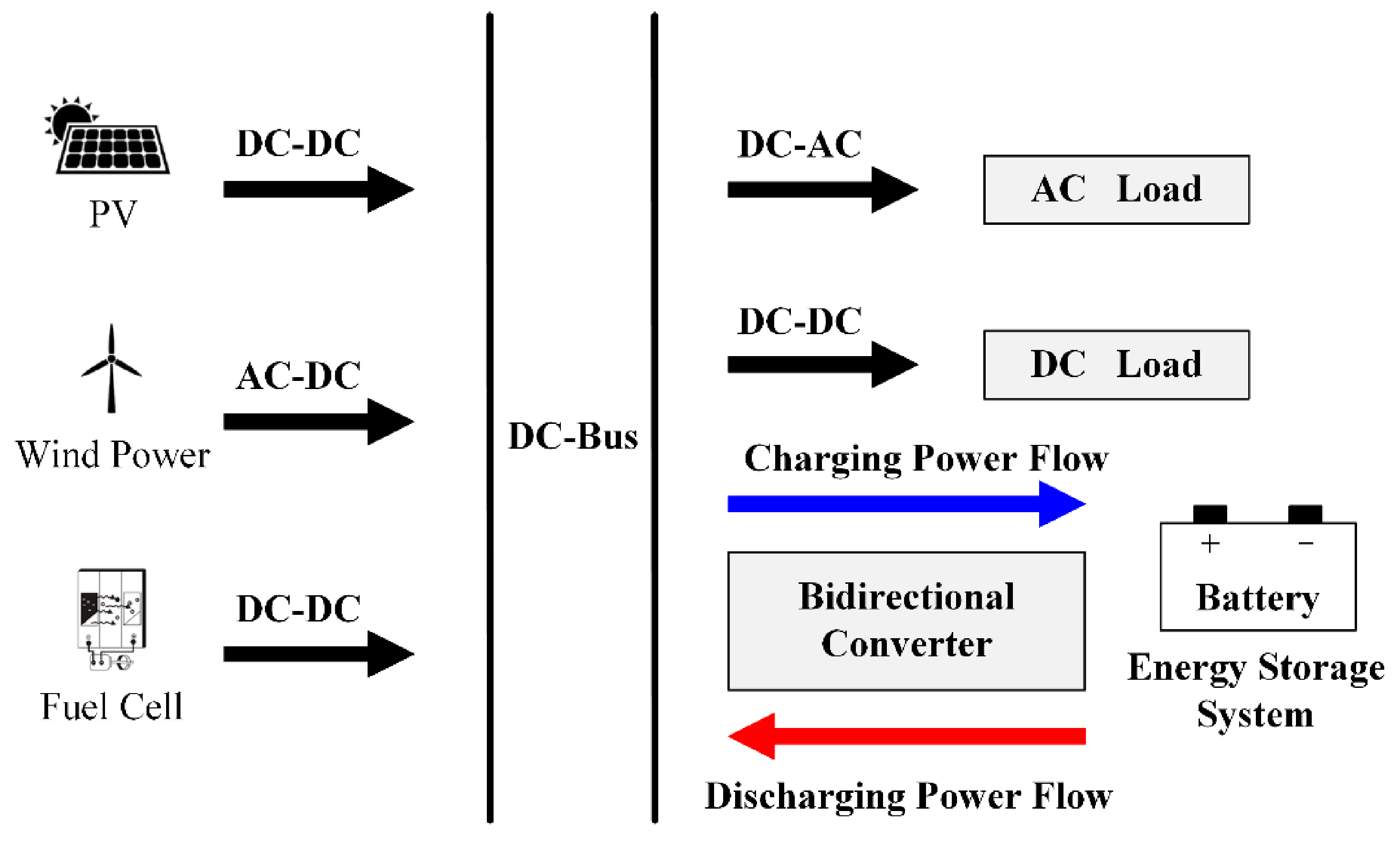
:1. Introduction
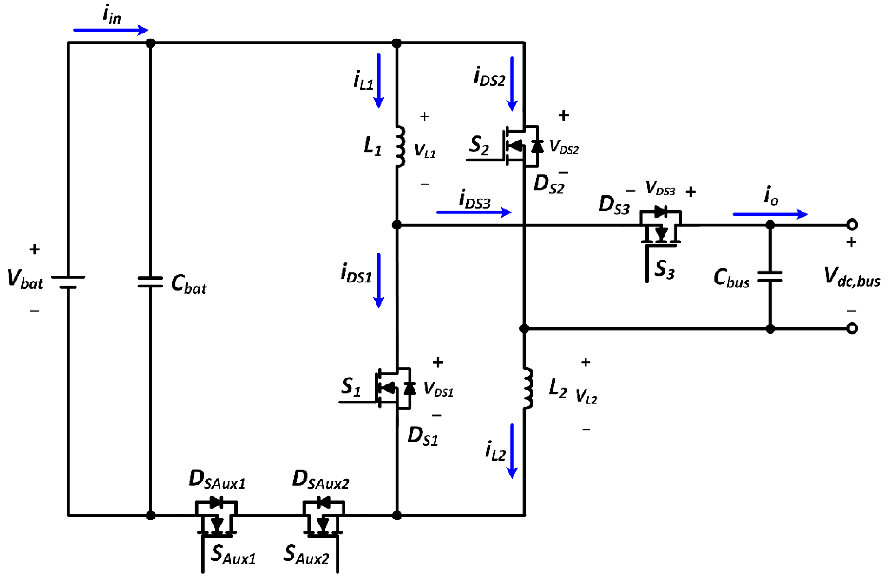
2. Operational Principle of Proposed Converter
- The converter is operated at the steady state.
- The converter is operated in CCM condition.
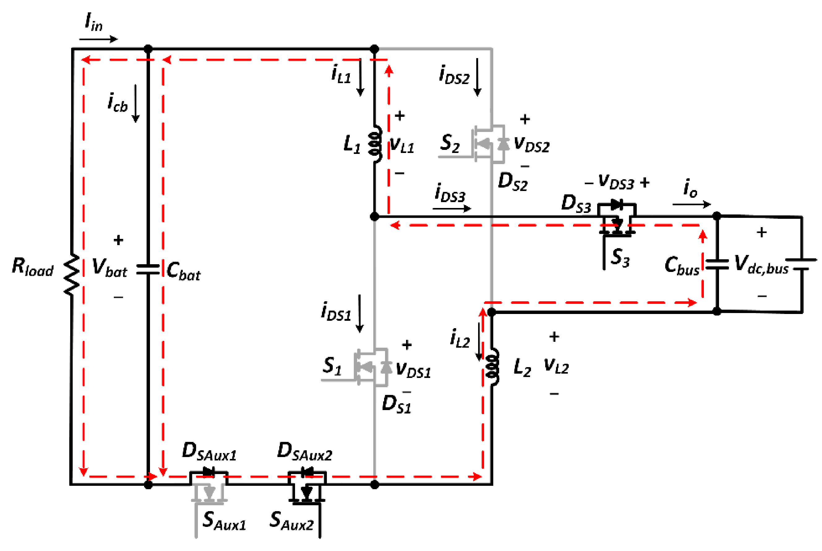
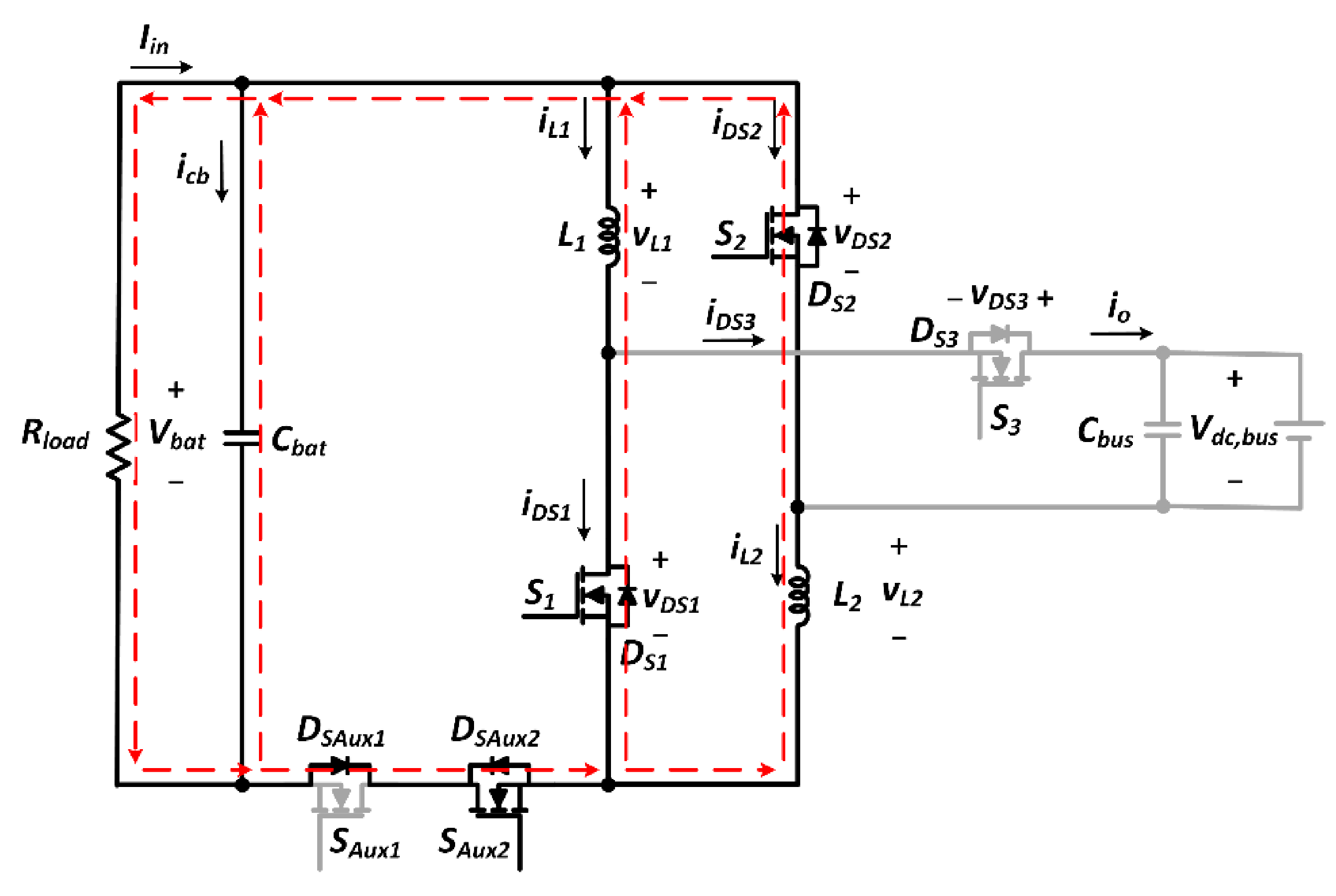
- The Body diodes of the power switches S1, S2, S3, SAux1, and SAux2 should be considered, corresponding to diodes DS1, DS2, DS3, DSAux1, and DSAux2.
- The capacitances of Cbat and Cbus are large enough to be regarded as a constant voltage source.
- The other components are assumed with ideal conditions except for the components indicated above.

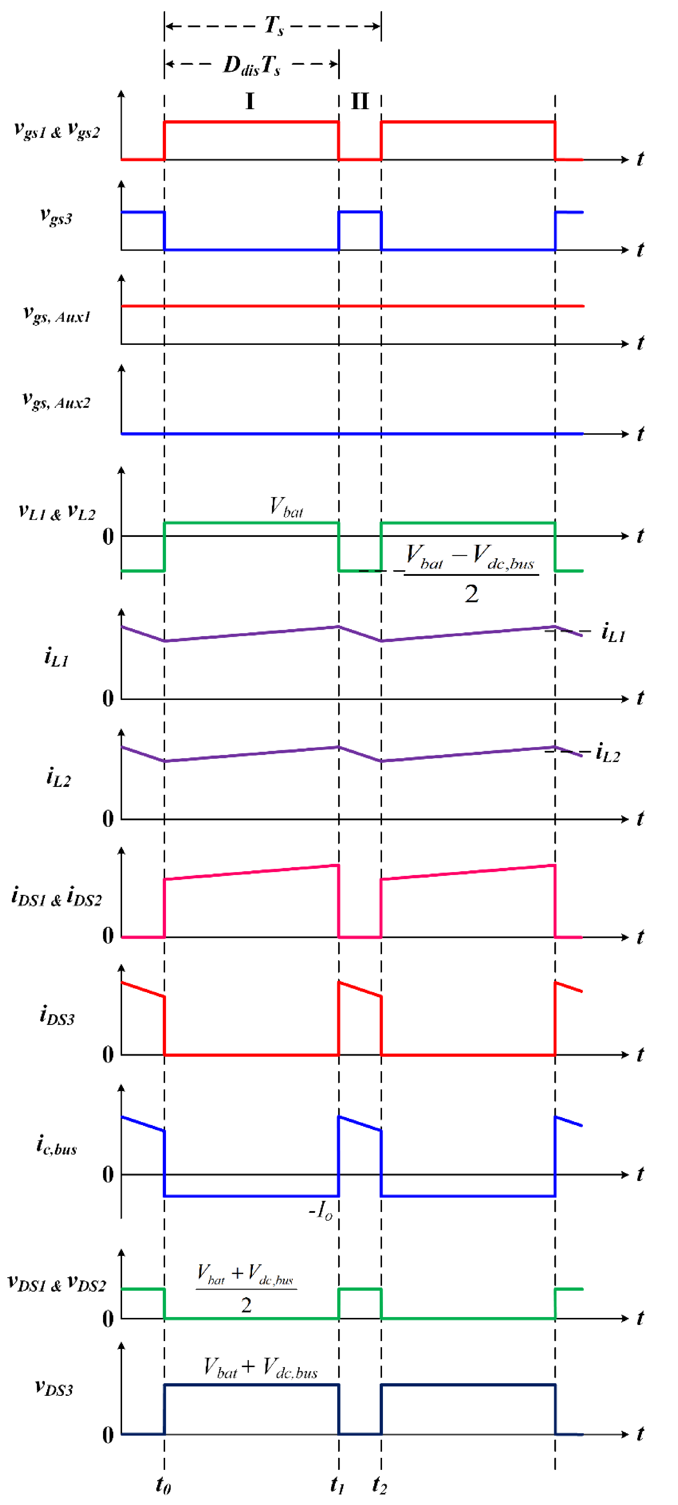
2.1. Step-Up Mode
2.1.1. Mode I (t0–t1)
2.1.2. Mode II (t1–t2)


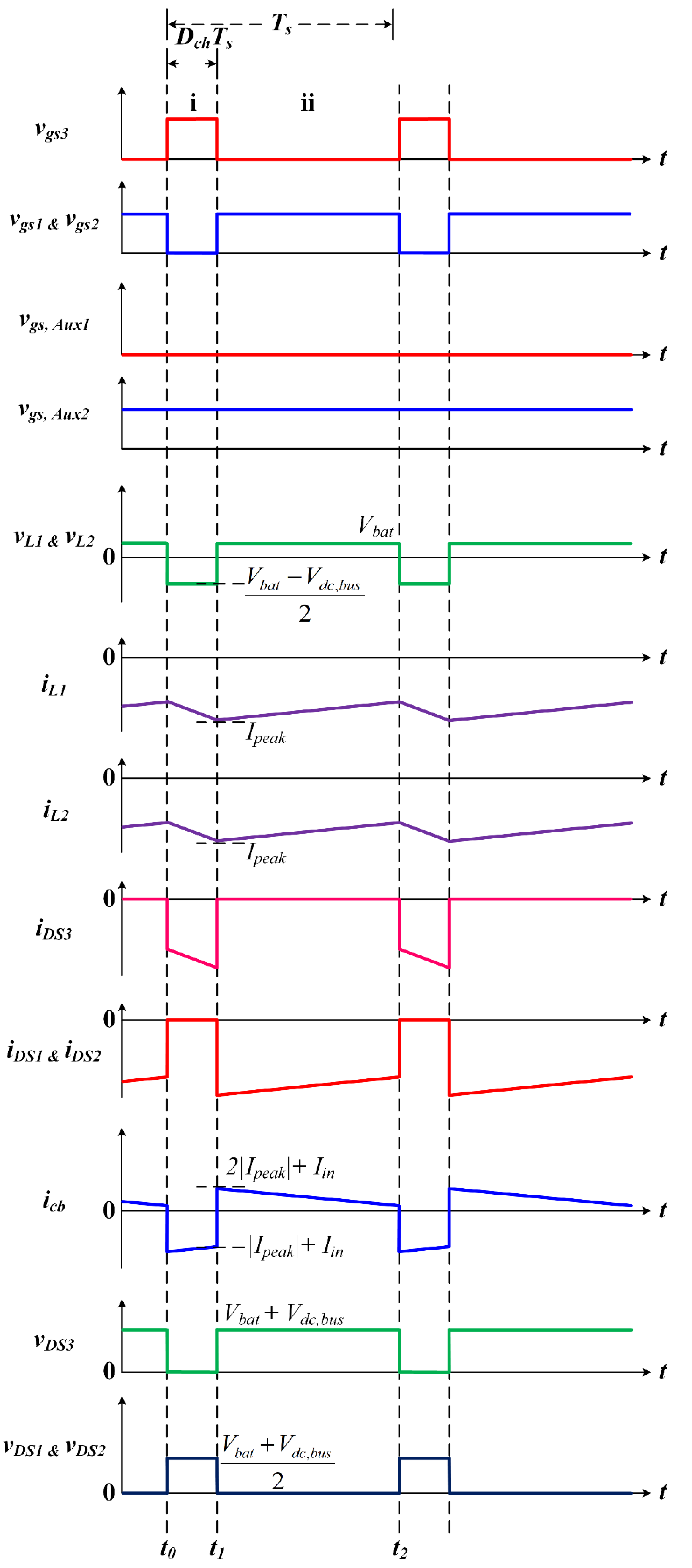
2.2. Step-Down Mode
2.2.1. Mode i (t0–t1)
2.2.2. Mode ii (t1–t2)
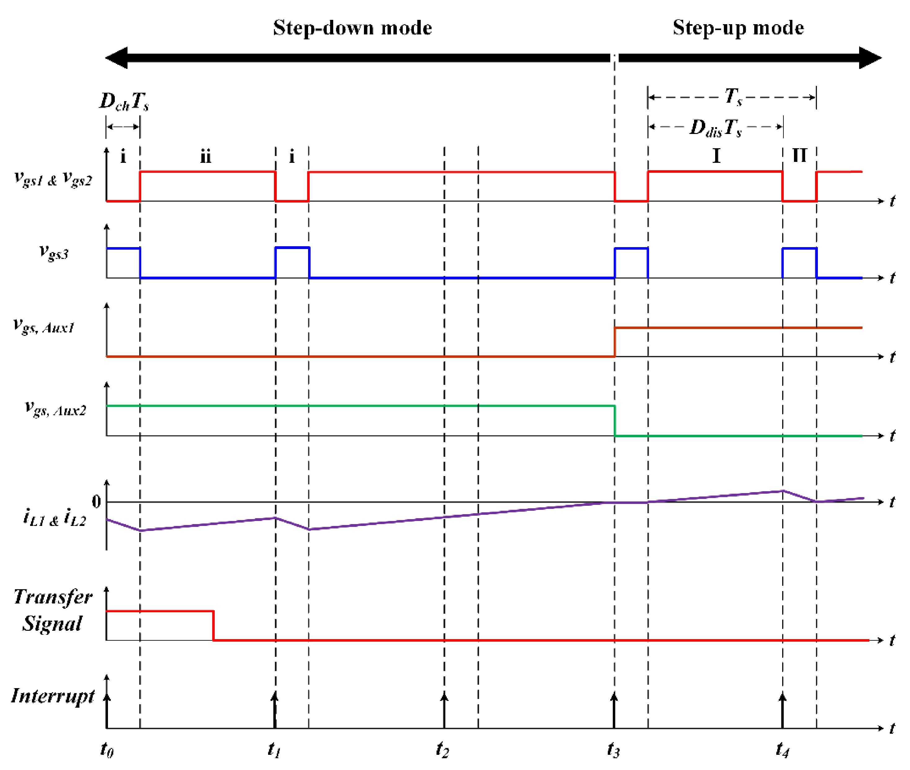
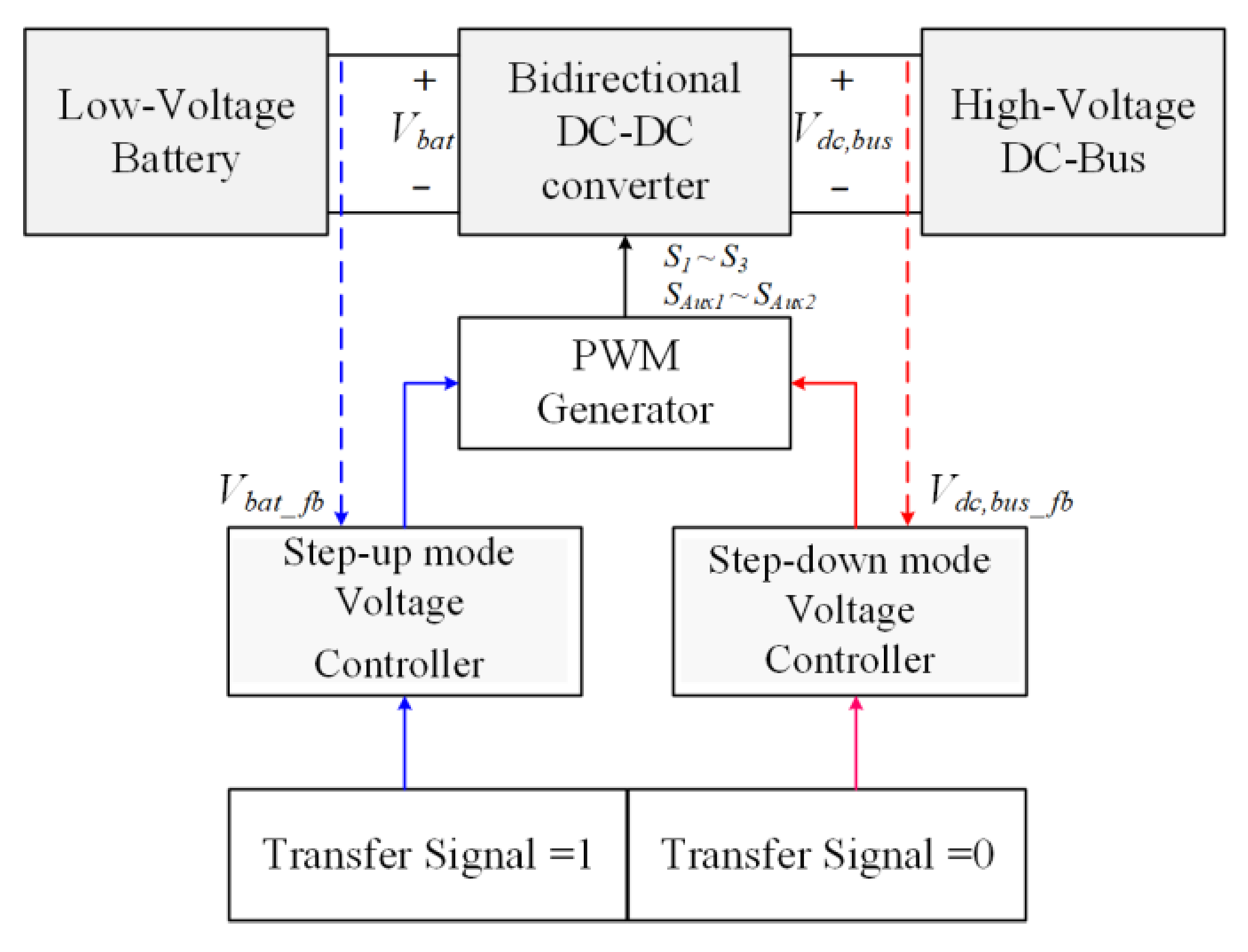
3. Control Strategy of Transferring State
- Step 1:
- Detect the status of the transfer signal and determine whether the converter changes the operating mode or not.
- Step 2:
- The gate driving signals of the bidirectional switches SAux1 and SAux2 maintain the original operating mode until the inductor currents iL1 and iL2 demagnetize to zero.
- Step 3:
- The gate driving signals of the bidirectional switches SAux1 and SAux2 change the original operating mode.
- Step 4:
- Finally, restore the gate driving signals of the main switches S1, S2, and S3.
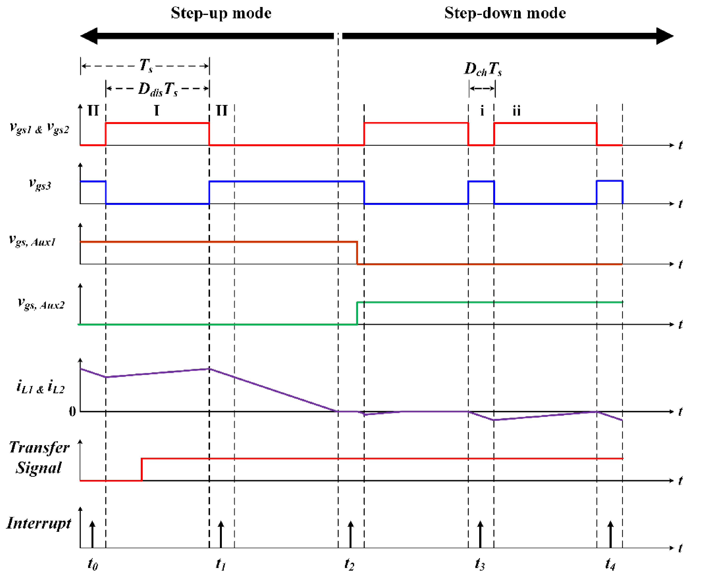
3.1. Transferring State from Step-Up Mode to Step-Down Mode

3.2. Transferring State from Step-Down Mode to Step-Up Mode
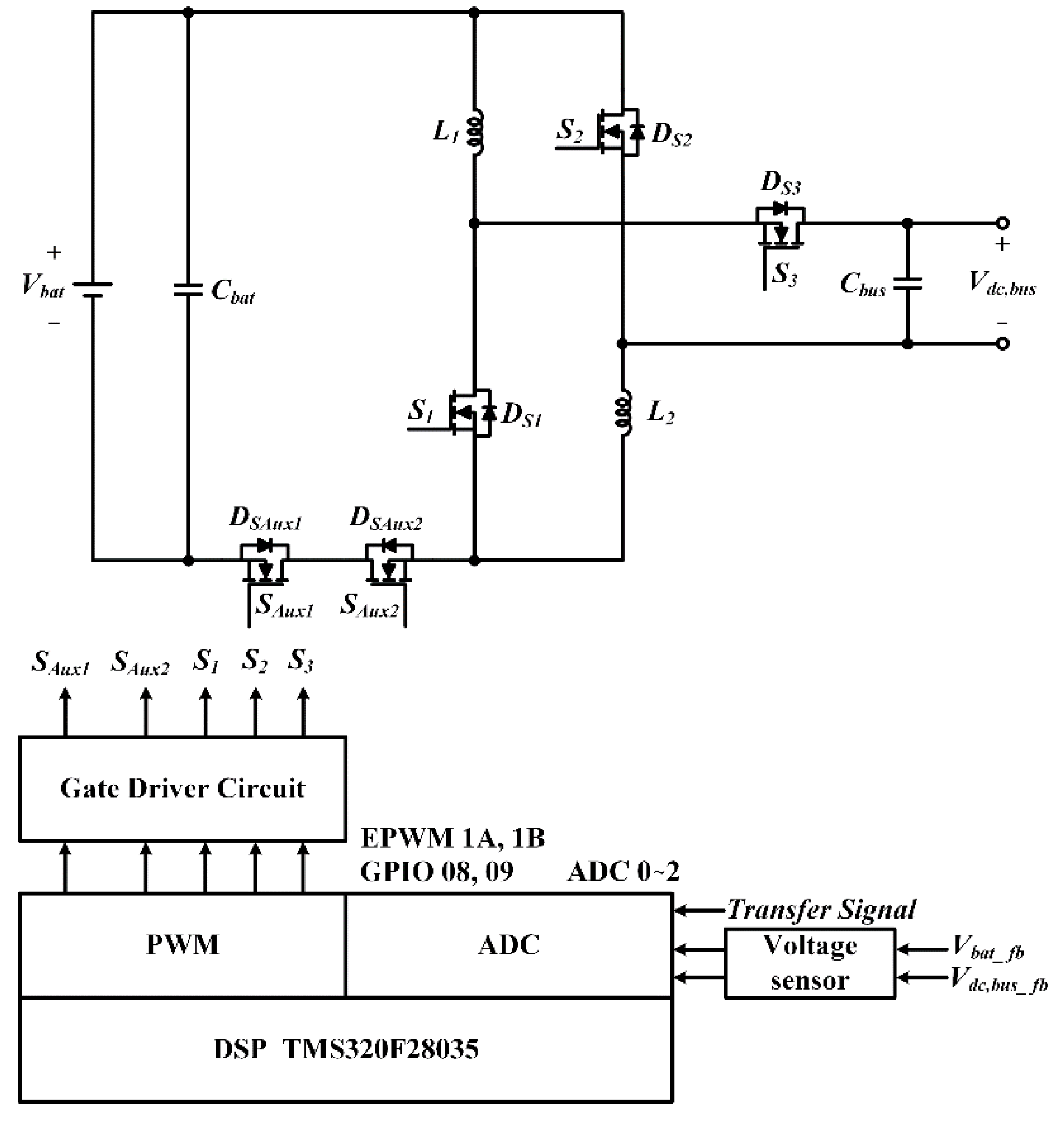
3.3. Flow Chart of the Digital Control System
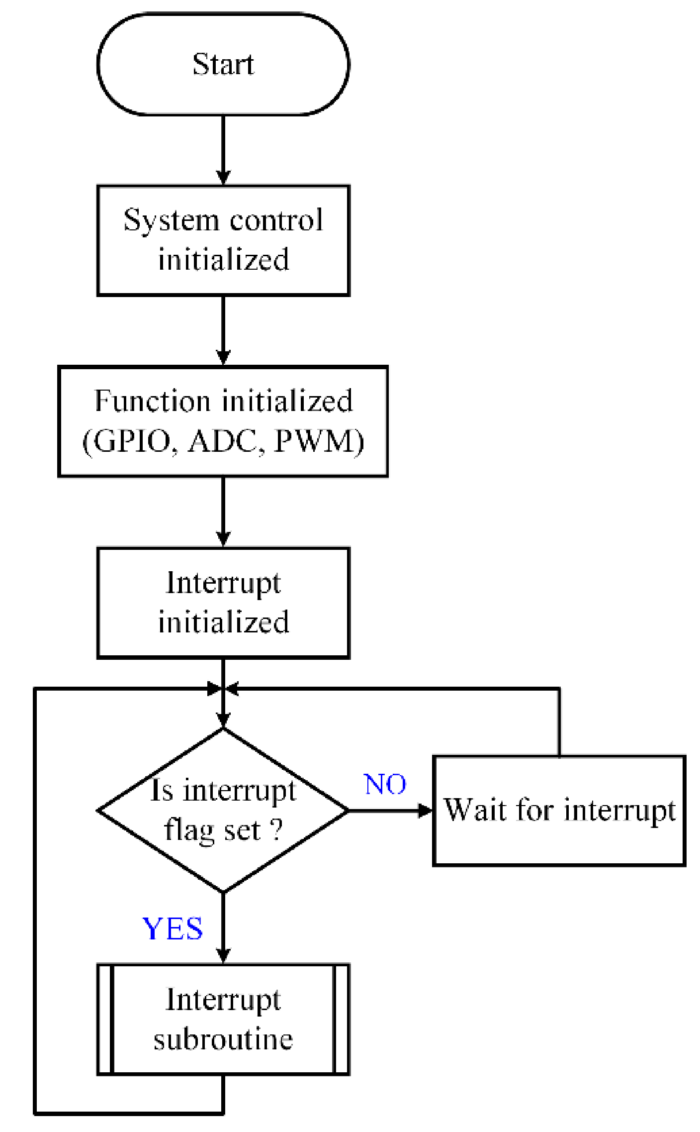
- If the time-base counter operates in the up-count mode and the initial value of the counter is zero, the counter value increases until the PRD value is reached. The time-based counter is then reset to zero and then recount from zero to PRD value again. The cycle period of the count value is equivalent to one system cycle.
- When the time-base counter equals zero, this event sets the flag of interrupt and enters the interrupt service routine. In addition, the ADC module is also e = set to perform the conversion.
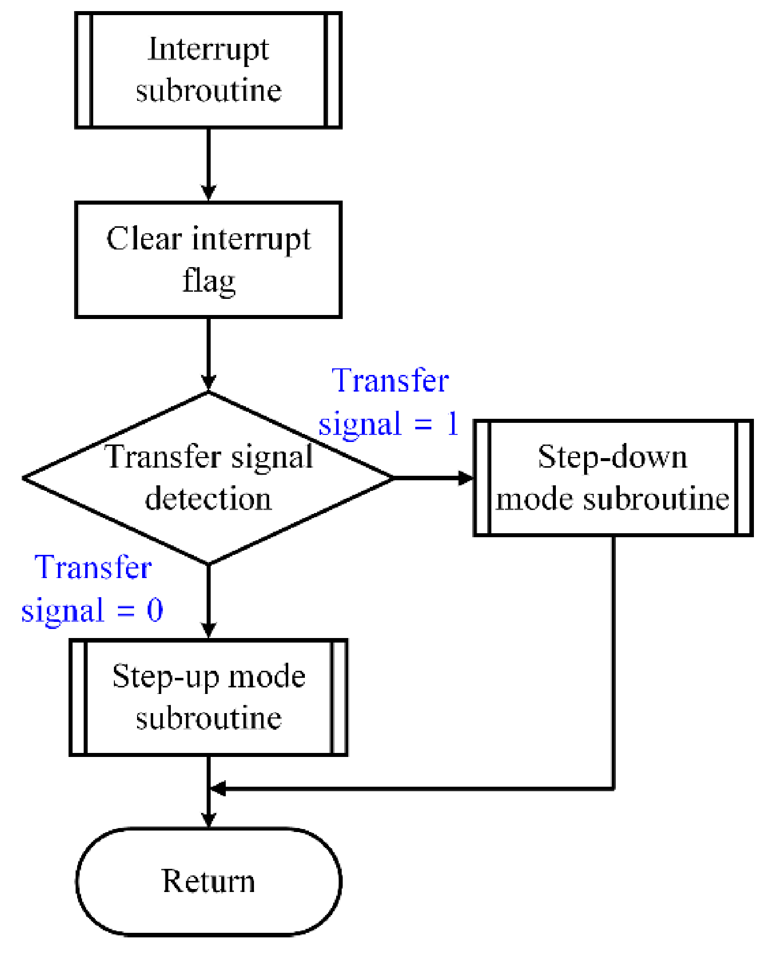
- After entering the interrupt service routine, the flag of interrupt must be cleared first so that the interrupt subroutine can be executed next time.
- Finally, the state of the transfer signal is detected to determine at which mode the converter is operating. If the transfer signal is detected as 0, the converter operates in the discharging mode. On contrary, if the transfer signal is detected as 1, the converter operates in the charging mode.
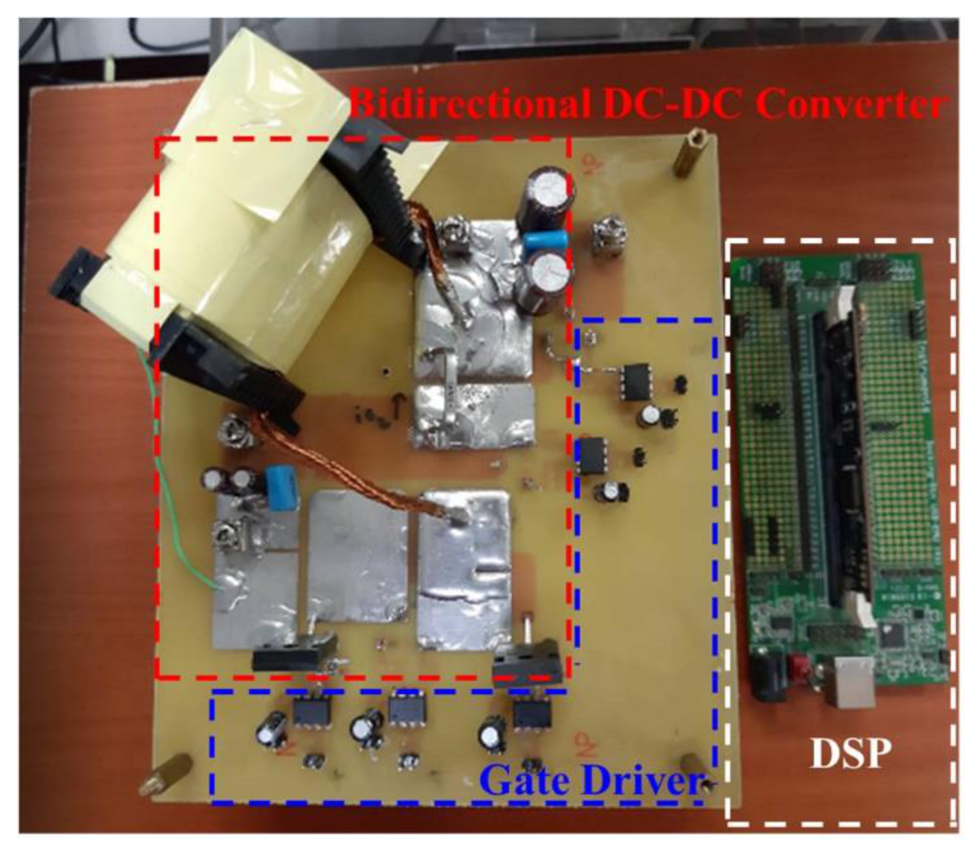
4. Experimental Results
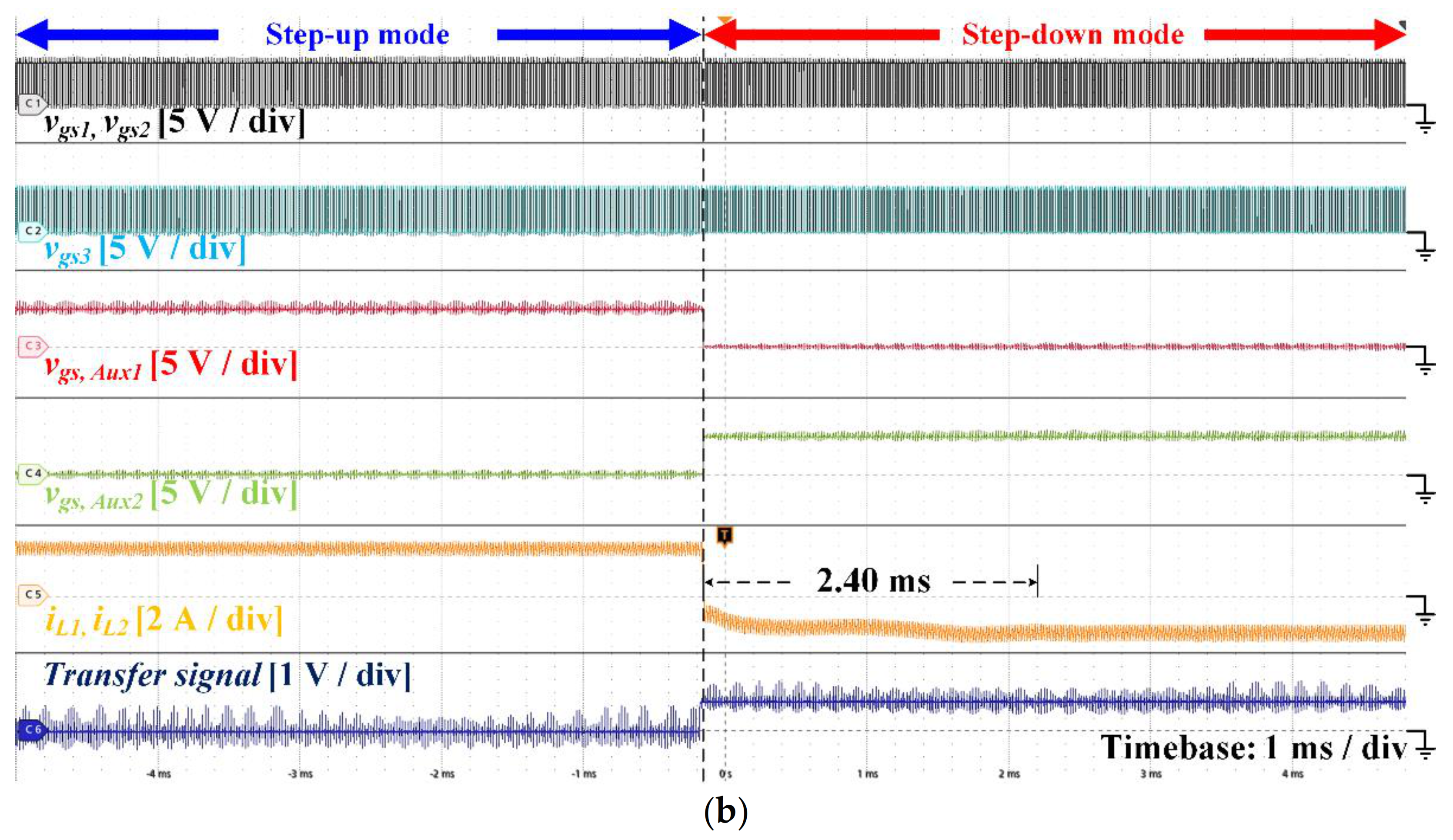
4.1. Step-Up Mode to Step-Down Mode (CCM Condition)
4.2. Step-Down Mode to Step-Up Mode (CCM Condition)
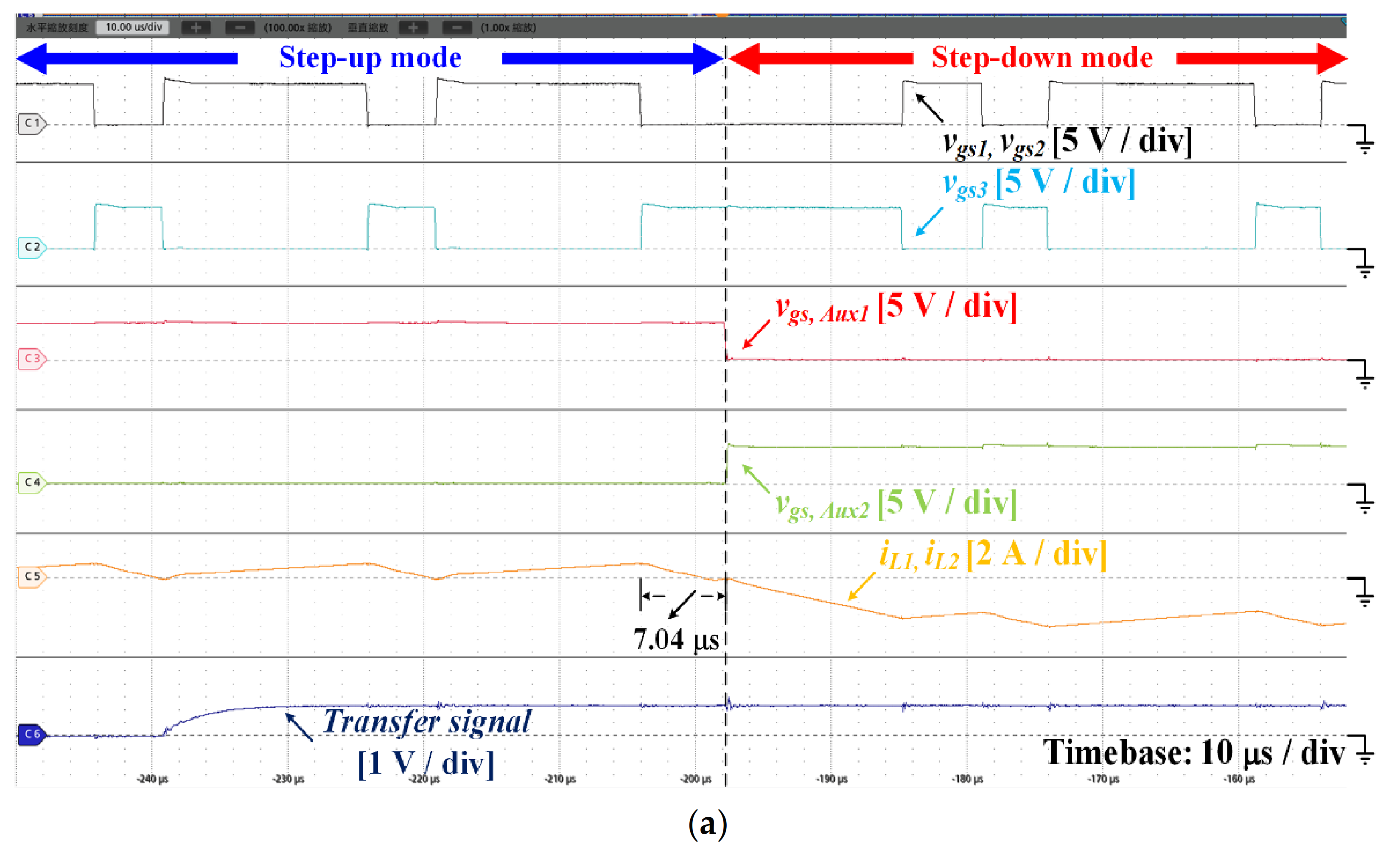
4.3. Step-Up Mode to Step-Down Mode (BCM Condition)
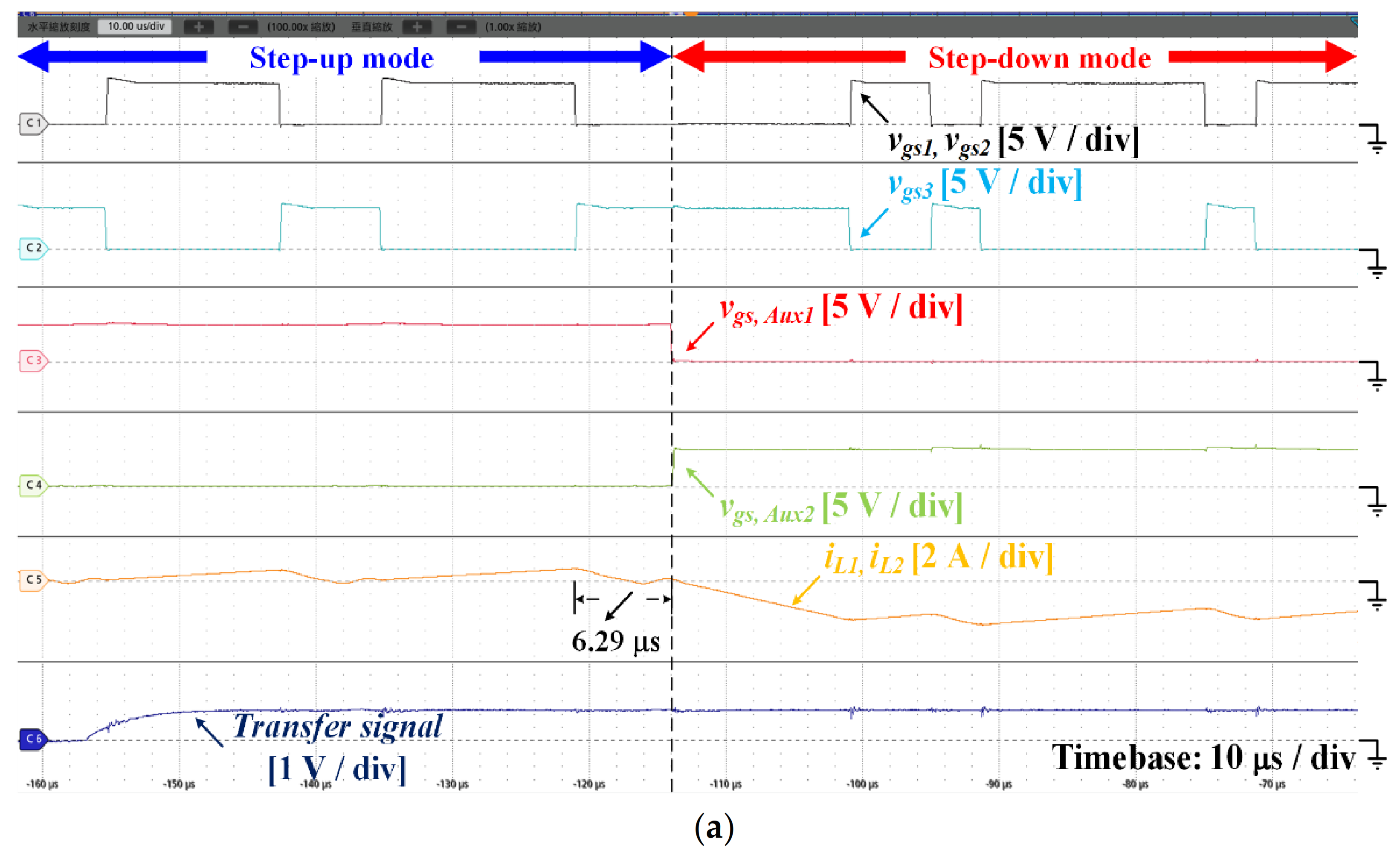
4.4. Step-Up Mode to Step-Down Mode (DCM Condition)
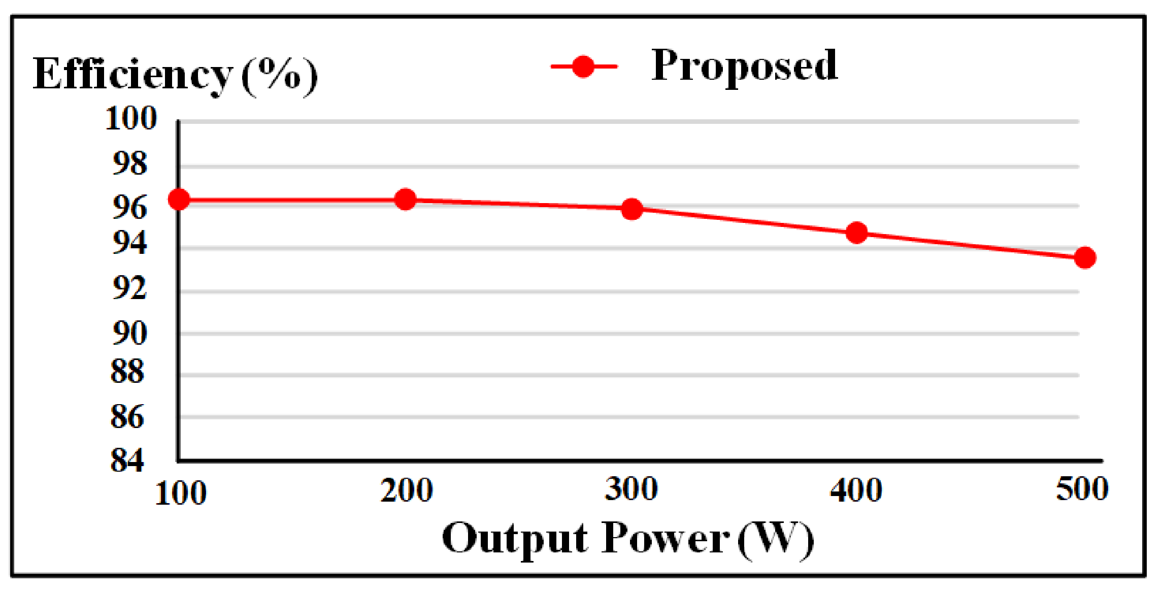
4.5. Efficiency under Step-Up Mode
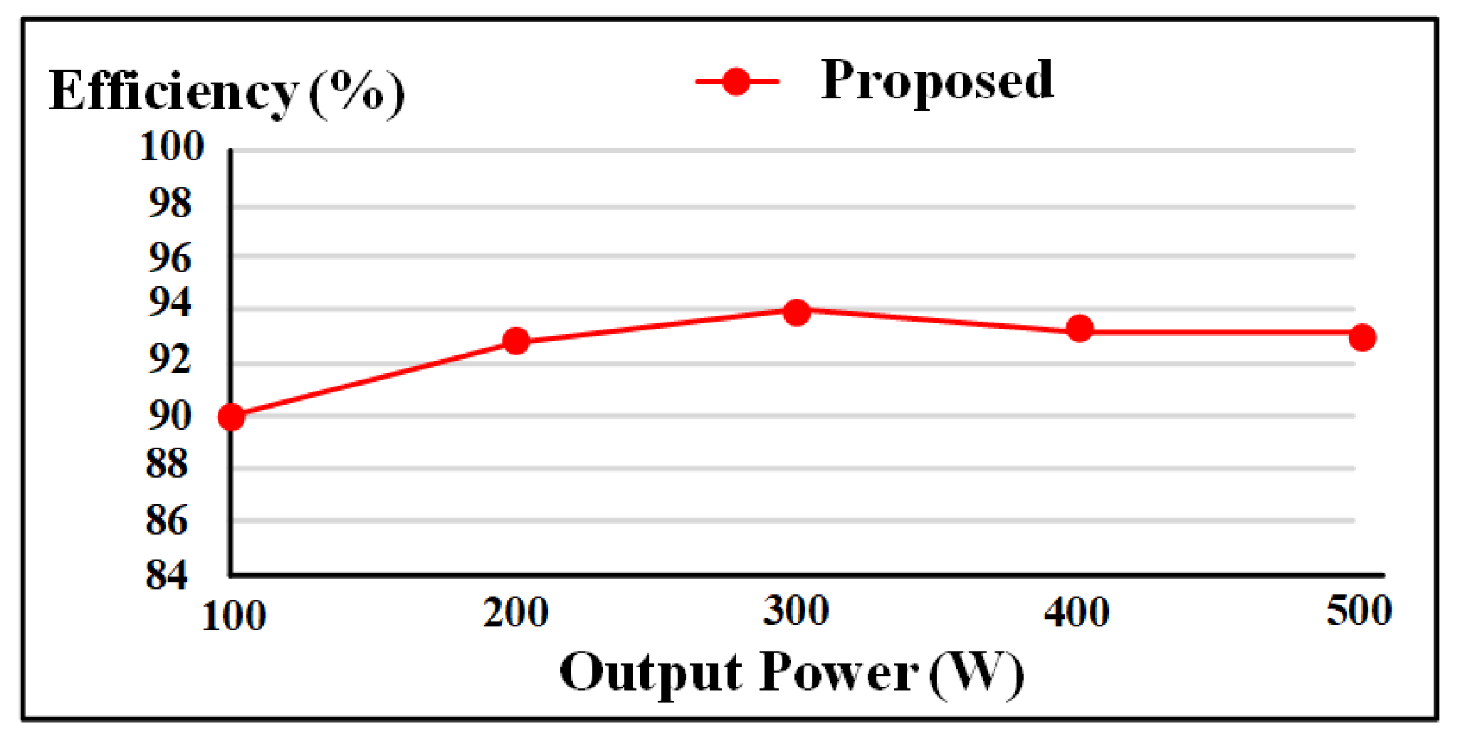
4.6. Efficiency under Step-Down Mode
5. Conclusions
Author Contributions
Funding
Institutional Review Board Statement
Informed Consent Statement
Conflicts of Interest
References
- Uang, Y.; Javanroodi, K.; Nik, V.M. Climate Change and Renewable Energy Generation in Europ—Long-Term Impact Assessment on Solar and Wind Energy High-Resilution Future Climate Data and Considering Climate Uncertainties. Energies 2022, 15, 302. [Google Scholar] [CrossRef]
- Arraño-Vargas, F.; Shen, Z.; Jiang, S.; Fletcher, J.; Konstantinou, G. Challenges and measures in Power Systems with High Share of Renewables—The Australian Expperience. Energies 2022, 15, 429. [Google Scholar] [CrossRef]
- Cardenas, B.; Styles, L.S.; Rouse, J.; Garvey, S.D. Short-, Medium- and Long-Duration Energy Storage in a 100% Reneable Electricity Grid: A UK Case Study. Energies 2022, 14, 8524. [Google Scholar] [CrossRef]
- Chen, S.; Yang, B.; Pu, T.; Chang, C.; Lin, R. Active Current Sharing of a Parallel DC-DC Converters System Using Bat Algorithm Optimized Two-DOF PID Control. IEEE Access 2019, 7, 84757–84769. [Google Scholar] [CrossRef]
- Bora, B.; Gudy, S.K. Performance and Analysis of Adaptable PI and SMC for a Hybrid PV-Battery System. In Proceedings of the 2020 IEEE International Women in Engineering (WIE) Conference on Electrical and Computer Engineering (WIECON-ECE), Bhubaneswar, India, 26–27 December 2020; pp. 84–89. [Google Scholar] [CrossRef]
- Han, Y.; Ning, X.; Yang, P.; Xu, L. Review of Power Sharing, Voltage Restoration and Stabilization Techniques in Hierarchical Controlled DC Microgrids. IEEE Access 2019, 7, 149202–149223. [Google Scholar] [CrossRef]
- Wu, H.; Sun, K.; Chen, L.; Zhu, L.; Xing, Y. High step-up/step-down soft-switching bidirectional DC-DC converter with coupled-inductor and voltage matching control for energy storage systems. IEEE Trans. Ind. Electron. 2016, 63, 2892–2903. [Google Scholar] [CrossRef]
- Kwon, O.; Kim, J.; Kwon, J.; Kwon, B. Bidirectional Grid-Connected Single-Power-Conversion Converter with Low-Input Battery Voltage. IEEE Trans. Ind. Electron. 2018, 65, 3136–3144. [Google Scholar] [CrossRef]
- Liang, T.J.; Lee, J. Novel high-conversion-ratio high-efficiency isolated bidirectional DC-DC converter. IEEE Trans. Ind. Electron. 2015, 62, 4492–4503. [Google Scholar] [CrossRef]
- Bai, S.; Lukic, S.M. Unified active filter and energy storage system for an MW electric vehicle charging station. IEEE Trans. Power Electron. 2013, 28, 5793–5803. [Google Scholar] [CrossRef]
- Bryden, T.S.; Hilton, G.; Dimitrov, B.; de León, C.P.; Cruden, A. Rating a Stationary Energy Storage System Within a Fast Electric Vehicle Charging Station Considering User Waiting Times. IEEE Trans. Transp. Electrif. 2019, 5, 879–889. [Google Scholar] [CrossRef] [Green Version]
- Venkatramanan, D.; John, V. A Reconfigurable Solar Photovoltaic Grid-Tied Inverter Architecture for Enhanced Energy Access in Backup Power Applications. IEEE Trans. Ind. Electron. 2020, 67, 10531–10541. [Google Scholar] [CrossRef] [Green Version]
- IEEE Guide for Batteries for Uninterruptible Power Supply Systems (Revision of IEEE 1184-1994). In IEEE Std 1184-2006(R2011); IEEE: New York, NY, USA, 2006; pp. 1–73. [CrossRef]
- Mozos, A.B.; Mouli, G.R.C.; Bauer, P. Evaluation of topologies for a solar powered bidirectional electric vehicle charger. IET Power Electron. 2019, 12, 3675–3687. [Google Scholar] [CrossRef]
- Zheng, Y.; Li, S.; Dey, S.; Smedley, K. Family of isolated bidirectional resonant converters with duty-cycle control and automatic power flow transition. IET Power Electron. 2018, 11, 1582–1590. [Google Scholar] [CrossRef]
- Sharma, A.; Nag, S.S.; Bhuvaneswari, G.; Veerachary, M. An improved mode transition technique for a non-isolated bidirectional DC-DC converter. IEEE Trans. Circuits Syst. II 2020, 67, 3093–3097. [Google Scholar] [CrossRef]
- Cornea, O.; Andreescu, G.; Muntean, N.; Hulea, D. Bidirectional power flow control in a DC microgrid through a switched-capacitor cell hybrid DC-DC converter. IEEE Trans. Ind. Electron. 2017, 64, 3012–3022. [Google Scholar] [CrossRef]
- Vuyyuru, U.; Maiti, S.; Chakraborty, C. Active power flow control between DC Microgrids. IEEE Trans. Smart Grid 2019, 10, 5712–5723. [Google Scholar] [CrossRef]
- Bayati, M.; Farahmandrad, M.; Tehrani, K. More and Faster Energy Transfer Capability for Battery Chargers of Electric Vehicles. In Proceedings of the 2021 World Automation Congress (WAC), Paris, France, 24–26 August 2021; pp. 228–232. [Google Scholar] [CrossRef]
- Khan, I.A.; Pi, D.; Yue, P.; Li, B.; Khan, Z.U.; Hussain, Y.; Nawaz, A. Efficient behavior specification and bidirectional gated recurrent units-based intrusion detection method for industrial control systems. IET Electron. Lett. 2020, 56, 27–30. [Google Scholar] [CrossRef]
- Callegaro, L.; Ciobotaru, M.; Pagano, D.J.; Turano, E.; Fletcher, J.E. A simple smooth transition technique for the noninverting buck-boost converter. IEEE Trans. Power Electron. 2018, 33, 4906–4915. [Google Scholar] [CrossRef]
- Tang, Y.; Chen, Y.; Madawala, U.K.; Thrimawithana, D.J.; Ma, H. A new controller for bidirectional wireless power transfer systems. IEEE Trans. Power Electron. 2018, 33, 9076–9087. [Google Scholar] [CrossRef]
- Xu, J. PWM modulation and control strategy for LLC-DCX converter to achieve bidirectional power flow in facing with resonant parameters variation. IEEE Access 2019, 7, 54693–54704. [Google Scholar] [CrossRef]
- Waghmare, T.; Chaturvedi, P. Study of Bidirectional DC-DC Converter: Control Schemes and Switching Techniques. In Proceedings of the 2020 IEEE First International Conference on Smart Technologies for Power, Energy and Control (STPEC), Nagpur, India, 25–26 September 2020; pp. 1–6. [Google Scholar] [CrossRef]
- Bhaskar, M.S.; Meraj, M.; Iqbal, A.; Padmanaban, S. Nonisolated Symmetrical Interleaved Multilevel Boost Converter with Reduction in Voltage Rating of Capacitors for High-Voltage Microgrid Applications. IEEE Trans. Ind. Appl. 2019, 55, 7410–7424. [Google Scholar] [CrossRef]
- Zhu, R.; Hoffmann, F.; Vázquez, N.; Wang, K.; Liserre, M. Asymmetrical bidirectional DC-DC converter with limited reverse power rating in smart transformer. IEEE Trans. Power Electron. 2020, 35, 6895–6905. [Google Scholar] [CrossRef]


| Step-Up Mode | Step-Down Mode | ||
|---|---|---|---|
| Battery Voltage, Vbat | 24 V | DC Bus Voltage, Vdc,bus | 200 V |
| DC Bus Voltage, Vdc,bus | 200 V | Battery Voltage, Vbat | 24 V |
| Step-up Power, Pdis | 500 W | Step-down Power, Pb | 500 W |
| Switching Frequency, fs1 | 50 kHz | Switching Frequency, fs2 | 50 kHz |
| Item | Value |
|---|---|
| Inductors L1, L2 | 185 μH |
| Capacitor Cbat | 56 μF/35 V |
| Capacitor Cdc,bus | 22 μF/250 V |
| Main Switches S1, S2, S3 | IMW65R048M1H |
| Bidirectional Switches SAux1, SAux2 | FDH055N15A |
| Mode | DCM | BCM | CCM |
|---|---|---|---|
| Step-up to Step-down | 6.29 μs | 7.04 μs | 15.8 μs |
| Step-down to Step-up | <20 μs | <20 μs | 50.01 μs |
Publisher’s Note: MDPI stays neutral with regard to jurisdictional claims in published maps and institutional affiliations. |
© 2022 by the authors. Licensee MDPI, Basel, Switzerland. This article is an open access article distributed under the terms and conditions of the Creative Commons Attribution (CC BY) license (https://creativecommons.org/licenses/by/4.0/).
Share and Cite
Chen, B.-Z.; Liao, H.; Chen, L.; Chen, J.-F. Design and Implementation of the Bidirectional DC-DC Converter with Rapid Energy Conversion. Energies 2022, 15, 898. https://doi.org/10.3390/en15030898
Chen B-Z, Liao H, Chen L, Chen J-F. Design and Implementation of the Bidirectional DC-DC Converter with Rapid Energy Conversion. Energies. 2022; 15(3):898. https://doi.org/10.3390/en15030898
Chicago/Turabian StyleChen, Bing-Zhang, Hsuan Liao, Linda Chen, and Jiann-Fuh Chen. 2022. "Design and Implementation of the Bidirectional DC-DC Converter with Rapid Energy Conversion" Energies 15, no. 3: 898. https://doi.org/10.3390/en15030898
APA StyleChen, B.-Z., Liao, H., Chen, L., & Chen, J.-F. (2022). Design and Implementation of the Bidirectional DC-DC Converter with Rapid Energy Conversion. Energies, 15(3), 898. https://doi.org/10.3390/en15030898