1. Introduction
Due to the high storage and transportation risk factors, the efficient use of pressure energy has long plagued researchers. Whether the pressure energy is converted from other energy or associated pressure energy, it must be used or converted in time to efficiently use its resources. A gas wave refrigerator (also called a thermal separator) is a piece of equipment that uses gas pressure to expand and refrigerate [
1,
2]. Its advantages include simple structure, low cost [
3], convenient operation and maintenance, high pressure resistance, operation with liquid, low power consumption, etc. The basic principle is to inject high pressure gas from a rotating distributor (rotary type) or a wall jet oscillator (static type) into several gas wave tubes with initial openings in turn. The pulse jet formed will perform expansion work on the stagnant gas in the tube, and the enthalpy of the jet gas itself will be lowered and cooled [
4].
Research on static gas wave refrigerators is still in the development stage. The air wave tube (also called the receiving tube) is closed at the end to eject air intermittently. A “contact surface” formed between the ejected air and the trapped air in the tube moves forward, and multiple compression waves are continuously generated until a positive shock wave is formed [
2,
5]. The shock wave sweeps the gas along the tube, increasing the temperature and pressure of the gas; the energy of the shock wave dissipates as it is transmitted to the gas through the tube wall, thereby greatly reducing the enthalpy and temperature of the incident gas (refrigeration) [
6,
7]. The forward movement of the shock wave continuously transfers energy to the original gas in the tube, thereby attenuating the shock wave. However, when the shock wave is not completely attenuated, it can move to the end of the tube and reflect back to the outlet of the gas wave tube. The reflected shock wave will have two adverse effects on gas refrigeration. The first is to heat the cold air that was refrigerated to be discharged, such that the temperature of the cold air rises again. The second is to increase the pressure of the jet inlet, increase the oscillator load, and reduce the incident pressure ratio. Both losses will directly reduce the efficiency of gas wave refrigeration.
Elimination the reflected shock wave is an important research direction to improve the efficiency of gas wave refrigeration. The conventional method is to lengthen the gas wave tube to reduce the shock wave such that it is unable to reflect; however, this wastes a significant amount of materials, causes vibration and condensate accumulation, and blocks the gas wave tube, making the effective tube length heavy and short. Fang et al. [
8] proposed the addition of a shock absorption chamber with a limited volume at the end of each gas wave tube to dissipate and absorb the shock wave; the refrigeration efficiency was greatly improved, yet the fluctuation in the ejection frequency was still large. Hu et al. [
9] proposed using multiple shock absorption cavities in series to further attenuate the reflected shock waves. Zou et al. [
10,
11] experimentally studied the damping dissipation of wire mesh in the end of the gas wave tube, and Li et al. [
12]. experimentally studied the shock wave with an orifice composite structure and achieved certain results. Dai et al. [
13]. used CFD calculations to show that two composite structures can attenuate the shock wave to an acceptable level. In addition, Zhu [
14], Li [
15], and Liu et al. [
16] studied the matching of the length of the gas wave tube with the ejection frequency, such that the gas wave tube can operate at a high-efficiency ejection frequency and reduce the impact of reflected shock waves. It is also possible to increase the heat exchange by changing the tube wall structure, increasing the energy dissipation in the tube, and reducing the reflected shock wave. For example, in the research of Al-Obaidi et al. [
17,
18,
19], different dimple geometrical configurations with a combination of corrugated tubes and twisted tape were numerically investigated. The study found that vortices and rotational flow originated behind and near the dimple, twisted tape, and corrugation surfaces. The rotational flow and vortices promote mixing in flow between the thermal boundary layer and velocity boundary flow layer, thus increasing the heat transfer enhancement. This method can also improve refrigeration efficiency. Zou et al. [
10,
11] proposed moving the shock wave absorption chamber forward to a proper position behind the middle of the gas wave tube, creating a middle shock wave absorption chamber that was used to reduce the return of the reflected shock wave and fold the reflected shock wave back to the back section of the gas wave tube to accelerate its dissipation. The refrigeration efficiency was improved; however, there was significant incident energy loss in the fluid.
In a uniform straight gas wave tube, the reflected shock wave will maintain a high intensity and return to the exit position. If a wave-eliminating cavity is installed, the reflected shock wave can be attenuated by multiple reflections and energy dissipation in the cavity, and the intensity of the reflected returning shock wave will be significantly reduced, improving the cooling efficiency of a gas wave tube with the same tube length. In order to efficiently use the ejection pressure energy and reduce the reflected shock wave, one should also try to reconstruct the distribution and reflection of the wave system in the gas wave tube, improve the shock wave forward path, block the shock wave reflection, and increase the dissipation in the back section of the gas wave tube, thus improving shock wave attenuation. According to this idea, we proposed and studied the Helmholtz-type wave-elimination chamber structure, which was used to enhance the incident shock wave, prevent the return of the reflected shock wave, and fold the reflected shock wave back to the back section of the gas wave tube to accelerate energy dissipation and reduce the impact on the exit position of the reflected shock wave. Based on this, a new and efficient Helmholtz gas wave tube was developed.
2. Using CFD to Model the Chamber Geometry and Simulate the Flow Field of a Gas Wave Tube
2.1. Creating a Chamber Geometry Model
According to the previous analysis, to improve the efficiency of a static gas wave refrigerator it is necessary to increase the shock wave forward path, block the shock wave reflection, and increase the dissipation of the back section of the gas wave tube to promote shock wave attenuation. The proposed Helmholtz wave-elimination chamber structure is strictly symmetrical along the axis in geometry, and the three-dimensional model can be simplified to two-dimensional in the calculation. If the ejection frequency is controlled well, this cavity in the middle can make a small part of the shock wave that escapes from the left side of the cavity reflect the shock wave, which will meet the incident rightward expansion wave caused by the next ejection jet and the two will cancel out. Thus, the harm of the reflected shock waves is basically eliminated.
Figure 1 shows the schematic diagram of the Helmholtz wave-elimination chamber.
After the jet enters the chamber, the boundary layer disturbance is amplified by the resonance of the oscillating chamber to form an annular feedback flow vortex. The vortex ring further develops to form a large-area cavitation, blocking the continuity of the jet and forming a self-oscillating pulse jet.
Figure 2 shows the schematic diagram of a traditional wave-elimination chamber. Generally, after the jet enters the chamber, the boundary layer disturbance is amplified by the wave-elimination chamber and directly hits the wall of the vertical chamber. After a large amount of kinetic energy is lost, the feedback flow vortex is formed; however, the regular vortex ring cannot be completely formed, causing the jet to lose a significant amount of pressure.
This geometric model adopts the Helmholtz wave-elimination chamber and traditional wave-elimination chamber comparison model. The dimensionless parameters of Helmholtz geometry were obtained from the related literature [
20,
21,
22], and they can be used as a comparison with the traditional chamber. For comparison, these parameters are shown in
Table 1.
2.2. Calculation Models and Boundary Conditions
CFD was used to simulate a double-chamber gas wave tube with the traditional wave-elimination chamber and the Helmholtz wave-elimination chamber, designed in the middle of the tube; an absorption chamber was also added at the ends of the two kinds of gas wave tubes. The two kinds of tube structures and the calculation mesh division are shown in
Figure 3. Using a two-dimensional calculation model, a maximum mesh size of 0.2 mm was determined by independence analysis, and the mesh at the opening of the tube was densified.
The end absorption chamber was closed on the same side as the wave-elimination chamber; the front section of the middle wave-elimination chamber was
La = 2000 mm, the rear section was
Lb = 1000 mm, and the total length of the two kinds of tubes with the chamber was 3200 mm. Since only the efficiency of the two gas wave tubes were compared, the pulse flow setting was realized by programming the pulsating intake function (UDF) in the simulation process. We used a trapezoidal wave to simulate the incident wave. As shown in
Figure 4, the time for the rising and falling of the leading edge was 1/40 s of the period T.
The pulse jet function (UDF) shown in
Figure 4 is as follows:
where
t represents any time,
T is the oscillation period,
PA is the certain instantaneous excitation pressure value,
PL is the minimum pressure, and
Ph is the maximum pressure.
The total pressure of the gas wave tube port in the ejection stage was 0.2 MPa, 0.3 MPa, and 0.4 MPa, and the temperature was 300 K, the cold air exhaust stage was subsonic flow, the static pressure value of the fixed nozzle was 0.1 MPa, and the corresponding expansion ratios ε (the ratio of the total inlet pressure to the static outlet pressure) were 2, 3, and 4, respectively, at fixed wall boundaries. The gas hypothesis conformed to the ideal gas state equation. The gas injection frequency f was 25 Hz~80 Hz (in 5 Hz increments); the gas was assumed to conform to the ideal gas equation of state, and the viscosity was 1.789 × 10⁻⁵ kg/m·s.
2.3. Numerical Calculation Method
The inlet of the gas wave tube pulsating jet is transonic, and it produces compressible and strong turbulent flow. The Reynolds average method for solving the time-averaged Navier–Stokes equation should be adopted, considering that the nozzle jet is turbulent and the turbulent flow is a highly non-linear and complex flow. The simulation method adopts the two-equation realizable k-ε turbulence model, and the finite volume method is used to discretize the control equations [
23]. The diffusion term selects a central difference scheme with high computational efficiency and second-order accuracy, which converges quickly. The convection term is anisotropic. In order to avoid numerical oscillations, the MUSCL (Monotonic Upstream-centered Scheme for Conservation Laws) format of the Roe flux differential splitting in the upside-down style is used for discretization [
24], and the second-order fully implicit time step is used for iteration [
25].
2.4. Refrigeration Efficiency of the Gas Wave Tube
The refrigeration efficiency of the gas wave tube is the ratio of the actual enthalpy drop of the jet gas entering and exiting the gas wave tube to the ideal isentropic enthalpy drop. The specific heat of the ideal gas does not change with pressure, as shown in the following formula:
where
k is the isentropic process index of the gas,
Tin is the total temperature at the inlet of the jet gas, and
Tout is the time-average total temperature at the outlet of the gas wave tube.
During the simulation process, the mass-weighted average total temperature Tav of the outlet section of the gas wave tube is monitored over time. When the change with time is stable (we selected the seventh period), the outlet section of the gas wave tube outlet section Tav and Δt, the product of the mass flux Δm, are accumulated and then divided by the integral value m of the total exhaust mass at the outlet of the gas wave tube; finally, the time-average total temperature Tout of the gas at the outlet of the gas wave tube can be obtained.
3. Flow Field Simulation and Results Analysis of the Two Kinds of Chambers
For the three-dimensional simulation of the two cavities, the simulation conditions were as follows: the ejection frequency was 80 Hz, the total pressure of pulsating ejection was 0.3 MPa, the temperature was 300 K, the static pressure at the outlet stage was 0.1 MPa, and the corresponding expansion ratio ε was 3.
Figure 5 shows a cloud diagram of the velocity vortex field changes inside two kinds of chambers. It can be seen from the figure that the jet in the Helmholtz-wave-elimination chamber begins to spread from the edge of the jet with time after ejection. When the time of reaching the back chamber wall is t, the edge of the jet collides with the back wall of the wave-elimination chamber, forming a tiny backflow. The backflow forms a vortex in the wave-elimination chamber, and the formation of this vortex will in turn disturb the edge shear layer of the jet, forming positive feedback, and finally strengthening the vortex flow inside the oscillation chamber and intercepting the continuous jet to form a self-oscillating jet. In the traditional wave-elimination chamber, the time it takes for the jet to enter the chamber, the wave-elimination chamber to amplify the boundary layer disturbance, and the jet to directly hit the vertical chamber wall, is
t. After a large amount of kinetic energy is lost, the feedback flow vortex is formed; however, the regular vortex ring cannot be completely formed, causing the jet to lose a significant amount of pressure.
Figure 6 shows the pressure changes at the outlet of the two chambers. The Helmholtz chamber excited a stable self-oscillating jet under a condition of small pressure loss. The total pressure of the Helmholtz wave-elimination chamber was much higher than the traditional wave-breaking chamber. The total pressure retention rate increased by 7%. This shows that the forward collision of the jet in the traditional chamber consumes a great deal of energy. Reducing the jet pressure front jump speed and the slow pressure drop causes a large amount of energy loss when the jet collides with the back chamber wall and cannot be avoided. Therefore, the total outlet pressure is lower than in the Helmholtz chamber, which affects the refrigeration efficiency.
Figure 7 shows the outlet velocities of the two chambers. The Helmholtz wave-elimination chamber jet velocity loss was significantly lower than that of the traditional wave-elimination chamber, and the velocity increased by about 50 m/s, which also doubled the amplitude of the jet’s self-oscillation pulsation and increased the jet turbulence at the end of the gas wave tube, improving the energy dissipation efficiency.
We observed the effect of the change in the expansion ratio on the outlet pressure of the Helmholtz wave-elimination chamber. When the pulsating ejection frequency was 80 Hz, the total pressure of pulsating ejection was 0.2 MPa, 0.3 MPa, and 0.4 MPa, and the temperature was 300 K, the cold air exhaust stage was subsonic flow, the static pressure value of the fixed nozzle was 0.1 MPa, and the corresponding expansion ratios ε were 2, 3, and 4, respectively. It can be seen from
Figure 8 that reducing the expansion ratio slows down the pressure front jump speed and pressure drop speed. Therefore, the Helmholtz chamber would have a better effect on the end jet at a high expansion ratio.
4. Comparison and Analysis of the Efficiency of the Two Kinds of Gas Wave Tube Refrigeration
Through the method of two-dimensional numerical simulation, the calculation was carried out by combining different frequencies of pulsating jets with a closed gas wave tube structure. The intensity of the shock wave is defined as the ratio of the total gas pressure in the gas wave tube to the static pressure at the outlet. The changes in the shock wave intensity in the two gas wave tubes with time are shown in
Figure 9. Under the action of the wave elimination chamber, the reflected shock wave in the gas wave tube was significantly weakened; it can be seen that the Helmholtz gas wave tube P/P
os value was only 1.7, and the P/P
os value of the traditional gas wave tube was 1.9. The reflected shock wave intensity was reduced by about 11%.
Figure 10 shows the gas mass weighted average total temperature
Tav with time for the two gas wave tube structures in a cycle where the jet duty ratio was 1/2, the expansion ratios ε were 2, 3, and 4, and the jet frequencies f were 25 Hz and 80 Hz. It can be seen from the figure that the jet gas in the exhaust stage is expanded and cooled by the original gas in the compression tube and then discharged from the outlet to obtain a lower-temperature refrigerant gas. From
Figure 10a,b, it can be seen that the cooling temperature of the Helmholtz central wave-elimination chamber was significantly lower than that of the gas wave tube of the traditional wave-elimination chamber.
Figure 11 shows the numerical simulation of the refrigeration efficiency of the Helmholtz wave-elimination chamber and the traditional wave-elimination chamber as a function of the ejection frequency. Under the condition where the jet duty ratio was 1/2 and the expansion ratios ε were 2, 3, and 4, the refrigeration efficiency increased by about 11–18% with the frequency conversion; the refrigeration efficiency showed a relative increase of about 2.9% (50 Hz), 2% (40 Hz), and 2.2% (25 Hz). In addition, due to the increase in the expansion ratio, the turbulence intensity, the temperature difference, and the pressure gradient in the tube, the efficiency was generally slightly improved. Furthermore, because the temperature in the tube was higher, the wave speed increased. The corresponding efficiency extremes were also improved with the increase in the ejection frequency.
Through the numerical simulation method, combined with the structural calculation of the pulsating jet and the gas wave tube, it was shown that the Helmholtz-type gas wave tube reduces the loss of incident kinetic energy and increases the consumption of reflected shock waves. The reflected shock wave is reflected multiple times between the middle chamber and the end of the gas wave tube, which weakens the intensity of the reflected shock wave and improves the refrigeration efficiency of the gas wave tube.
5. Experimental Study and Comparison of Two Kinds of Gas Wave Tube Refrigeration Efficiency
We constructed a single-tube gas wave refrigerator to verify the influence on the refrigeration efficiency of the two gas wave tube structures. The exhaust gas of the single-tube small-volume gas wave refrigerator is easily affected by the temperature of the surrounding environment, making it difficult to accurately measure the exhaust temperature. However, if the changing law of environmental influence factors is observed, the contrasting values of different air wave tube structure refrigeration efficiencies are easy to measure and distinguish; hence, it is a more economical and effective experimental research method.
5.1. Experimental Facilities
The experimental device is shown in
Figure 12. The single-tube experimental machine was built by accurately aligning the jet nozzle with the opening of the single air wave tube and then fixing it. Between the nozzle and the gas wave tube orifice, a jet pulse modulation disc with two symmetrical and transparent arc openings was inserted. When the arc opening turns to the nozzle and the opening position of the gas wave tube, air is ejected into the gas wave tube. During the exhaust phase, the gas wave tube entrance is blocked by the pulse modulation disc, and the air flows out from the front end of the gas wave tube toward the outlet. According to the requirements of intake duty ratio 1/2 and duty ratio 1/4, the ratio of the transparent arc length to the closed arc length of the pulse modulation disc was 1:1 and 1:2, respectively, as shown in
Figure 13.
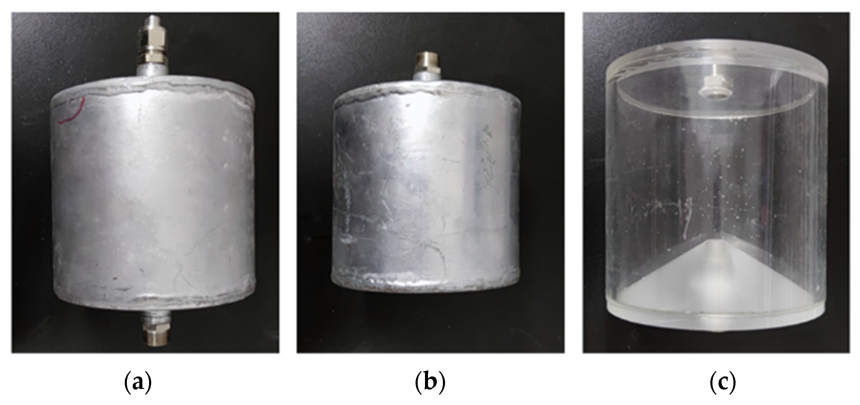
The pulse modulation disc was driven by an AC motor whose speed was regulated by a frequency converter. The frequency f was changed by adjusting the motor speed n (r/min). Because there were two arc-shaped openings on the disc, f = 2n/60 Hz. The outlet structure adopted an acrylic plate to engrave the flow channel; the gas wave tube was copper tube, the front tube length was 2000 mm, and the inner diameter was 10 mm. The distance between the two chambers of the two airwave tubes was 1000 mm, and the inner diameter of the tube was 10 mm. The inner diameter of the chamber was about 96 mm, and the length of the inner chamber was about 100 mm. There are three types of wave-elimination chamber. The first two are hollow cylinders made of aluminum. The difference between the two is whether both ends are open. These three structures are shown in
Figure 14. The Helmholtz wave-elimination chamber proposed in this paper was made of Plexiglass.
5.2. Experimental Results and Analysis
In the actual experiment, the ambient temperature was uncontrollable and was different from the idealized instantaneous ejection into the gas wave tube and instantaneous exhaust used in the simulation. For a certain distance between the nozzle and the gas wave tube opening, the jet caused a certain degree of loss before entering the gas wave tube, which, along with other complications, made the refrigeration efficiency obtained by the experiment lower than the value obtained by the simulation.
The pressure sensor (5) was inserted into the air supply pipe close to the nozzle to measure the total pressure Pin at the inlet of the air wave pipe. The valve was used to adjust the pressure to 0.1 and 0.2 MPa. The exhaust static pressure was the atmospheric pressure, and the corresponding expansion ratios ε were close to 2 and 3, respectively. A temperature sensor (4) was also inserted into the air supply pipe close to the nozzle for measurement, which was used as the total intake temperature Tout. For the measurement of the cooling temperature of the outlet air, because the modulation disc 9 was attached to the arc-shaped groove on the end of the gas wave tube, the pulse exhaust and reflection caused by the speed change made it difficult to accurately measure the exhaust temperature in the edge area of the pulse jet modulation disc. Therefore, this experiment adopted an indirect method that involved setting a flow channel near the opening of the gas wave tube, inserting a temperature sensor (2), measuring the time-average temperature Ta near the opening, and then approximately converting to the exhaust temperature Tout. Although the accurate refrigeration temperature cannot be measured in this way, it is clear enough that the measurement results of uniform conditions can be used to compare the refrigeration efficiency of various gas wave tubes.
Because the room temperature injection gas and the refrigerating gas alternately pass through the opening of the gas wave tube, and the ambient gas outside the metal gas wave tube heats the small amount of refrigerating gas, the time-average temperature Ta measured at the opening of the gas wave tube is much higher than the actual cooling discharge temperature Tout. Regardless of the influence of environmental heating, it is assumed that the heat transfer Q = mcpΔT of the ejection and exhaust gas to the sensor are equal. Assuming that the specific heat capacity cp is constant, and the mass m of injection and exhaust gas is equal, the following equations are given according to the relationship of equal heat transfer: Tin − Ta = Ta − Tout and Tout = 2Ta − Tin. The refrigeration efficiency values of different gas wave tube structures under different ejection conditions and frequency conditions can be calculated by substituting the calculated exhaust temperature Tout, the measured total intake temperature Tin, and the expansion ratio ε into Equation (2).
In fact, corresponding to the improved efficiency of the new gas wave tube, the ambient gas outside the tube had a greater impact on the refrigerant gas inside the tube, and the heating was also stronger. However, since the above simplified formula is not considered, the calculated efficiency curve gap between the two gas wave tubes is smaller than the actual value. In addition, the heating coefficient of the nozzle with the temperature difference is difficult to estimate, so it was not considered. This leads to a certain error in the results between the actual experiment and the numerical simulation under ideal boundary conditions; however, it is still accurate enough to compare the refrigeration efficiency of the two gas wave tubes.
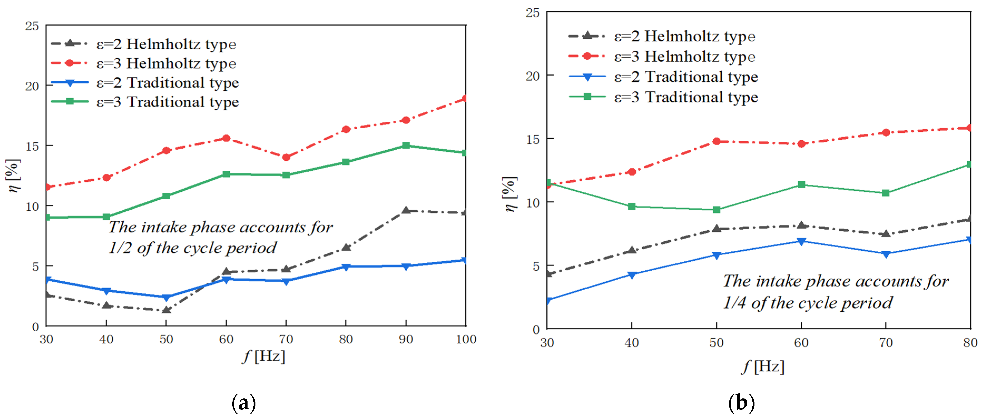
Figure 15a shows the cooling efficiency obtained from the measured time-average temperature at the exit section of the gas wave tube of the two structures under the condition where the jet duty ratio was 1/2 and the expansion ratios ε were 2 and 3. With the increase in frequency, the cooling efficiency also increased by 2% to 6%; the Helmholtz chopper chamber increased by about 3.5% (50 Hz) and 3.7% (90 Hz) compared with the gas wave tube of the traditional middle chopper chamber. In addition, the efficiency extreme value increased with the fluctuation of the ejection frequency.
Figure 15b shows the cooling efficiency obtained by the measured time-average temperature at the exit section of the gas wave tube of the two structures under the condition where the jet duty ratio was 1/4 and the expansion ratios ε were 2 and 3. The refrigeration efficiency also increased by 2% to 5%. The Helmholtz central wave-elimination chamber and the gas wave tube of the traditional central wave-elimination chamber were relatively improved by about 5% (50 Hz) and 2% (90 Hz), respectively.
It can be seen from the experimental results that the refrigeration efficiency and flatness of the Helmholtz wave-elimination chamber gas wave tube were significantly higher than that of the existing traditional wave-elimination chamber gas wave tube. The ejection frequencies corresponding to the peak and trough efficiency of the two kinds of gas wave tubes in the experiment were also basically consistent with the simulation results.


