1. Introduction
Solar energy is one of the major sources of renewable energy. This fact means that converting it into electricity is a very important research topic. A photovoltaic system can be defined as a system used for the transformation of solar energy into electrical energy. High cost and low efficiency are among the defects of photovoltaic systems. This event motivates scientists to investigate how to maximize the efficiency of renewable energy resources. Considerable attention is given to photovoltaic (PV) power generation systems as one of the most promising energy generation systems that can alternate with fossil fuel power generation [
1]. The PV industry has expanded rapidly in the last 20 years [
2]. It can also be seen that the installation of photovoltaic technology is increasing by 20–25% annually, mainly due to cost reduction. The cost reduction is driven by the improvement of solar cell efficiency, the improvement of production technology, and the development of economies of scale.
An inverter is required to transform the DC electricity coming from a photovoltaic generator into AC electricity [
3,
4]. One of the most important electronic components of a grid-connected PV inverter is the DC/AC inverter controller [
5]. Therefore, it received intensive research to optimize its performance. There are different types for the regulation of the controlling action of the controller. The conventional methods are based on proportional integral differential methods PID.
A PI controller is proposed as a solution for three-phase grid-connected inverter control. The proposed solution is simulated using PSIM and implemented in hardware to validate the results [
6]. A detailed description of the hardware implementation of the PI controller is presented in [
7]. The hardware uses a dsPIC microcontroller to control the inverter and produce a voltage that is synchronized with the grid voltage. The purpose of that research is to show a practical implementation of a control system for a grid-connected inverter (GCI) by using a dsPIC microcontroller. It is found that the conventional PI controllers are relatively slow and have more steady-state errors and more ripples compared to the fuzzy controllers [
7].
In [
8], a fuzzy controller, which is based on a special choice of a combination of inputs and outputs, is used. The selection of input and output, as well as fuzzy rules, is based on the principle of mathematical analysis of the derived function (slope) in order to find the best value. It can also be observed that by employing only three sets of linguistic variables to deconstruct the membership functions of the fuzzy controller’s inputs and outputs, the best results and answers from the photovoltaic system may be achieved [
8]. The fuzzy controllers can be also used for the maximum power point tracking in DC/DC converters of the PV generators. However, in partial shading, classical fuzzy MPPT fails to obtain the global maxima. [
9]. In order to overcome the FLC problem under shading conditions [
9], FLC is based on dynamic safety margin (DSM), similar to the MPPT algorithm of photovoltaic systems. The simulation results show that the proposed MPPT algorithm can detect the peak value at the global maximum point and manage the photovoltaic system. A two-fuzzy logic controller scheme [
10] is proposed to control the DC/DC converter and the inverter in a three-phase grid-connected inverter. The proposed scheme improves the power quality of the system. However, the research article presents a simulation study only.
The control strategy of the photovoltaic (PV) system in [
11] utilized a single-phase grid-connected inverter with low voltage ride-through (LVRT) capability which is controlled by a fuzzy logic controller. In reference [
12], a DC–DC boost converter is used to boost the DC voltage generated by a solar cell with an output voltage of 18 volts. In order to obtain good transient and steady-state performance, a typical 54 V fuzzy controller is suitable for DC–DC converters, and 24 V is suitable for DC–AC converters. They found that the created controller provided fast response and good performance. [
12].
In addition, a fuzzy logic controller for a three-phase grid-connected inverter has been designed and implemented in hardware [
13]. The fuzzy controller (FLC) was tested using a 260-watt photovoltaic system. Their results show that the FLC performs better with the PI controller [
13].
A fuzzy controller for controlling a grid inverter for 22 KV distribution systems was proposed. The experimental results showed that the intelligent controller increased the stability of the output voltage [
14].
In [
15], smart fuzzy was proposed to provide active and reactive power control for efficient low-voltage ride-through (LVRT) capabilities during grid faults. The logic proposed by fuzzy is based on an improved reactive and active power control strategy by injecting reactive current to stabilize the grid voltage. In addition to the fuzzy strategy of inverter control, the algorithm of a 1 kW solar photovoltaic grid-connected system was verified in real time on the hardware.
A research paper [
16] described an optimized fuzzy controller for grid-connected photovoltaic systems. The proposed controller is optimized using a nature-inspired optimization algorithm called LSA. In order to demonstrate the functioning of the proposed algorithm, a hardware prototype was realized [
16].
Ngoc-Tung Nguyen et al. [
17] introduced a fuzzy-PI controller to control a grid-connected inverter where they tuned the PI by fuzzy logic for various advantages such as being less expensive, covering a larger variety of operating circumstances, and improving the quality factor. Despite disturbances of the load and variations of input, the gain of the PI controller is tuned by the fuzzy algorithm [
17].
Regarding regulation of the inverter with a simplified fuzzy-PI controller (SFPIC) [
18], a linear control surface proposes a single input of fuzzy controller with its fuzzification and defuzzification processes. The proposed controller was shown to produce a comparable performance to its standard fuzzy-PI controller but with a significant reduction in computational time. A hardware implementation was realized to compare the simplified fuzzy-PI performance controller and the traditional fuzzy-PI controller [
18].
An interactive grid-connected inverter controlled by fuzzy-PI was developed and deployed [
19]. The PI controller’s proportionate and complete gains were determined according to the system operating point by the FLC. A self-adapting PI controller was realized, which can adapt to the fast transient response due to different operating conditions such as grid disturbances and natural influences. Both simulation and experimental results show that the system proposed has rapid dynamic responses with low overshoot and short adjustment times. The proposed inverter system was also compared to the conventional PI-controlled system [
19]. In a previous work [
20], a comparison between different controllers was worked out. It showed the superior performance of the fuzzy-PI controller. This motivated the researchers to develop a fuzzy-PI controller for their PV system [
20].
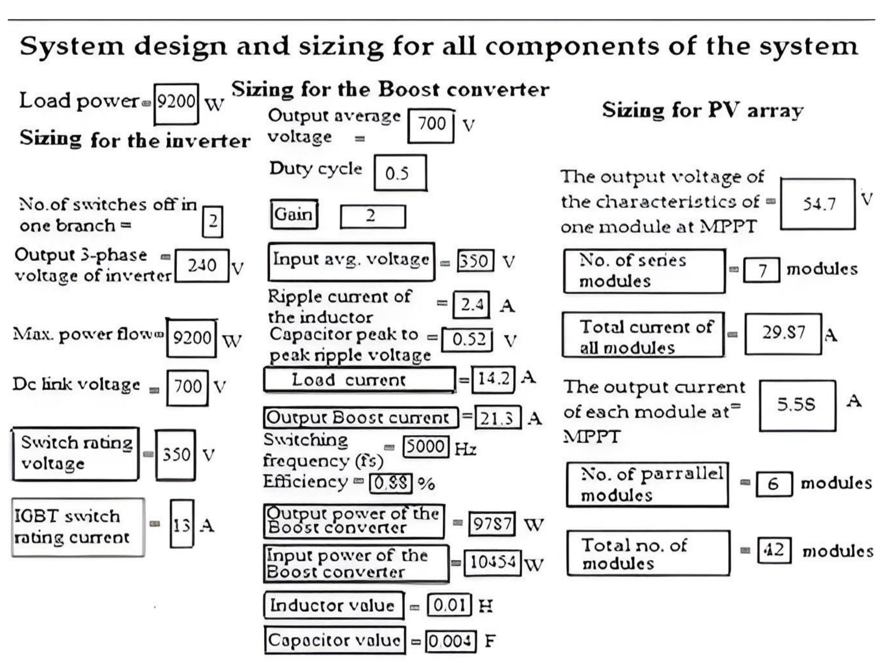
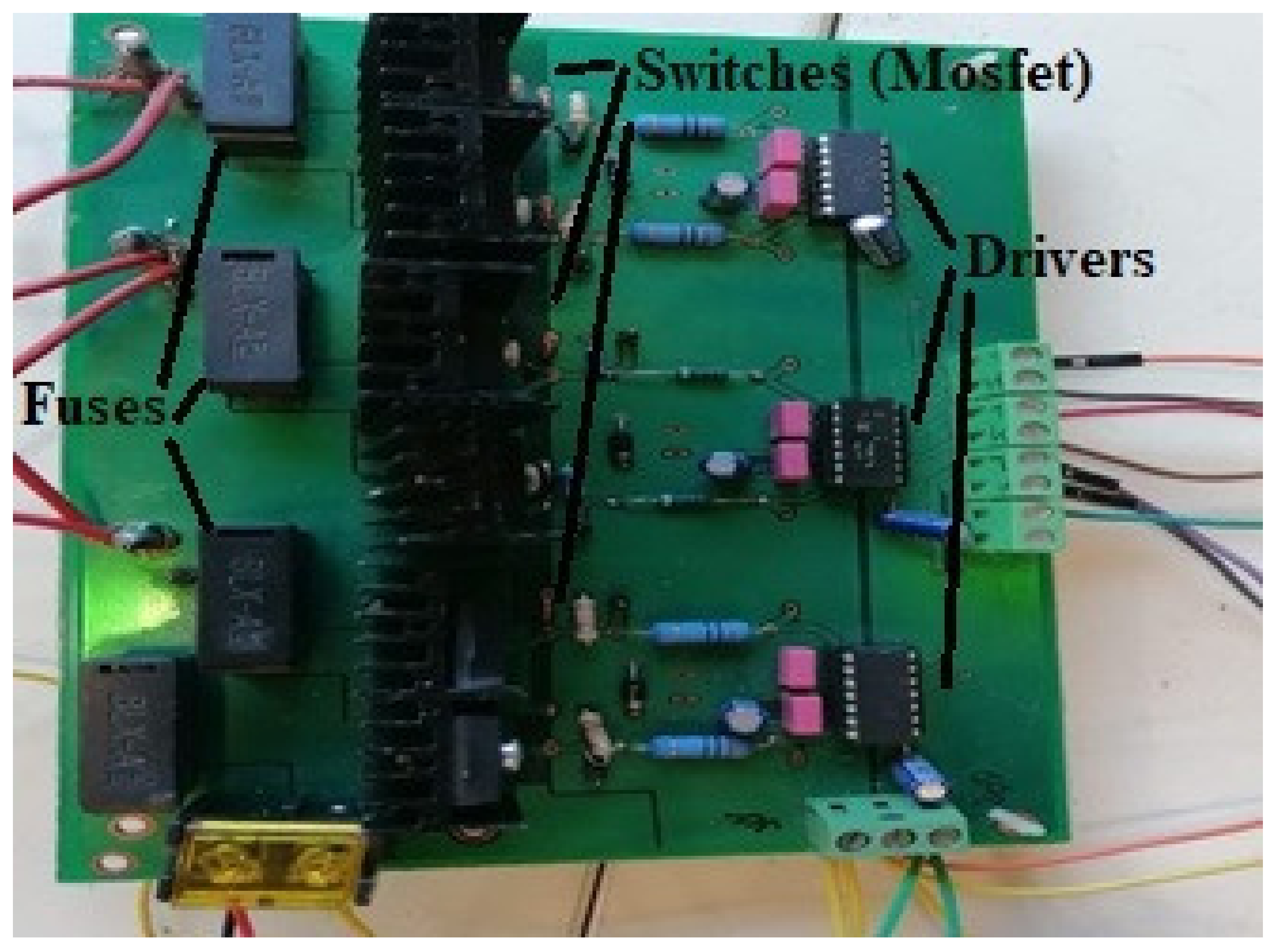
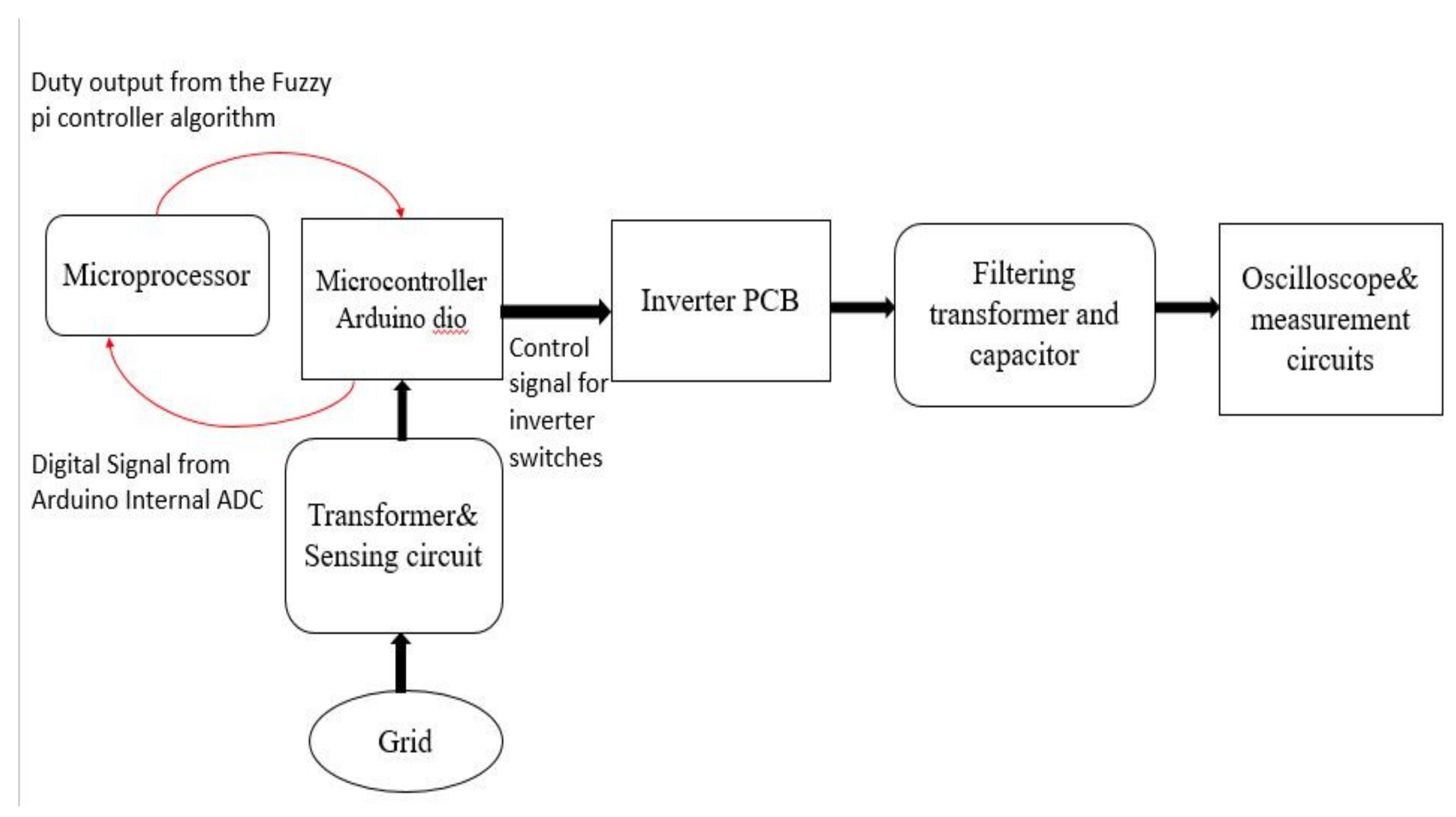
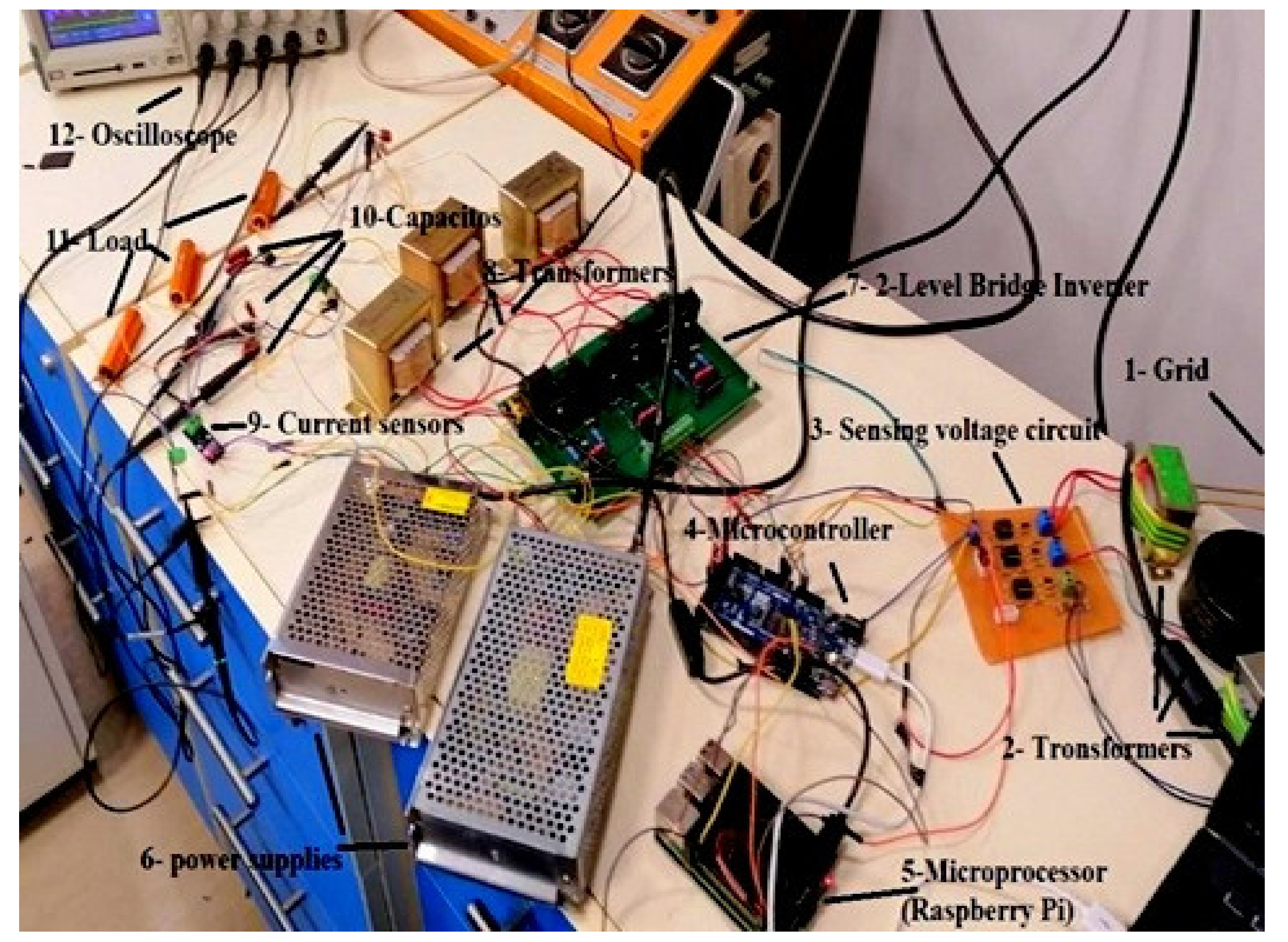
The main objective of this work is to introduce the design and hardware implementation of an intelligent controller (fuzzy-PI) for grid-connected photovoltaic generators in an average household. In terms of hardware implementation, the researchers used a 70 W prototype to test the controller for the sake of safety and cost issues. The proposed methodology does not need complex programming, as a Matlab control code is transformed to a C-control code for operating the electronic hardware design of the controller. Finally, the hardware setup is developed for verifying the simulation model of the system realized in Matlab.
The paper is organized as follows:
Section 2 describes the Simulink components of the PV system in detail.
Section 3 provides Simulink results.
Section 4 provides a GUI for system design and sizing for all components of the system modules.
Section 5 introduces a design and hardware implementation of an intelligent controller (fuzzy-PI) for the inverter part of a grid-connected PV system, code generation, and experimental results. In the hardware implementation, the researcher works with a 70 W prototype to test the controller.
Section 6 provides a conclusion and future work.
2. Complete Descriptions of the Simulink Components of PV System
This section presents a full description of the Matlab Simulink system that is built to test the fuzzy-PI controller.
Figure 1 shows the complete Simulink model for the system. On the left, there is a DC voltage source along with two decoupling capacitors. The idea is to model the effect of a PV panel source along with a converter. An exact model is not needed for the PV panel because the researcher concentrates on the inverter controller part. The output of the DC voltage along with decoupling capacitors goes through a two-level bridge inverter. The control signal of the two-level bridge inverter comes from the fuzzy-PI controller. The three-phase output of the inverter is input to the measurement block and then input to the LC filter. The LC filter is responsible for eliminating the disturbance from the three-phase signals. The LC filter output is connected to an AC load that has two options (high load and low load). On the other side, there are the grid and the measurement and display blocks.
2.1. Input Voltage
The basic components of the Simulink model consist of the following:
There is a use of a simplified I–V curve model introduced in other papers [
21].
In this Simulink model, the researcher is concerned with the inverter controller. The researcher uses the value of the voltage at the MPPT generated by the boost converter.
There is a model of a PV array and a boost converter with a single voltage source parallel with two series capacitors.
The paper [
21] shows that the voltage source model approximates the real photovoltaic panel operation.
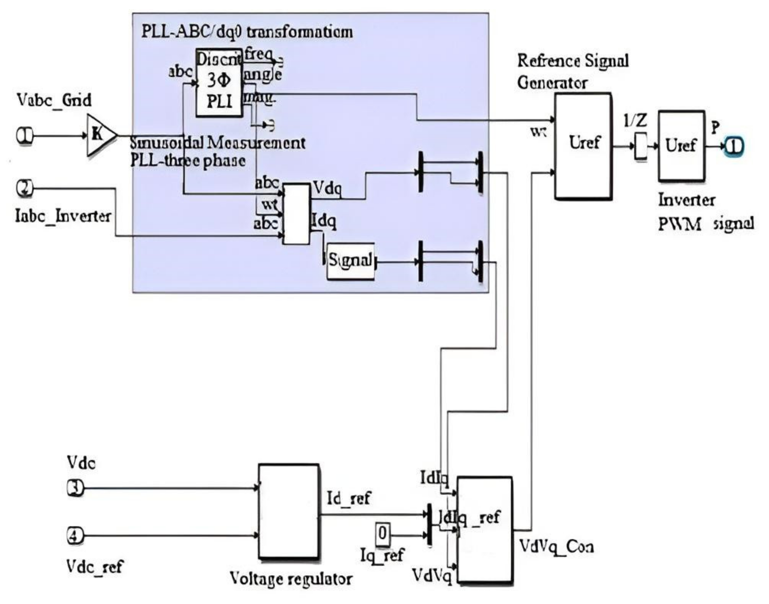
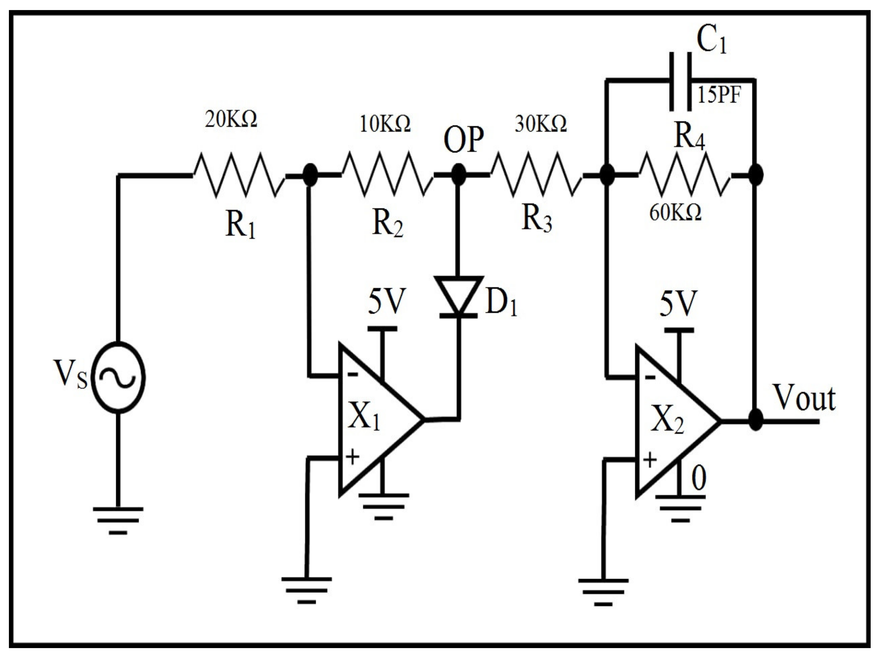
2.2. Fuzzy-PI Controller
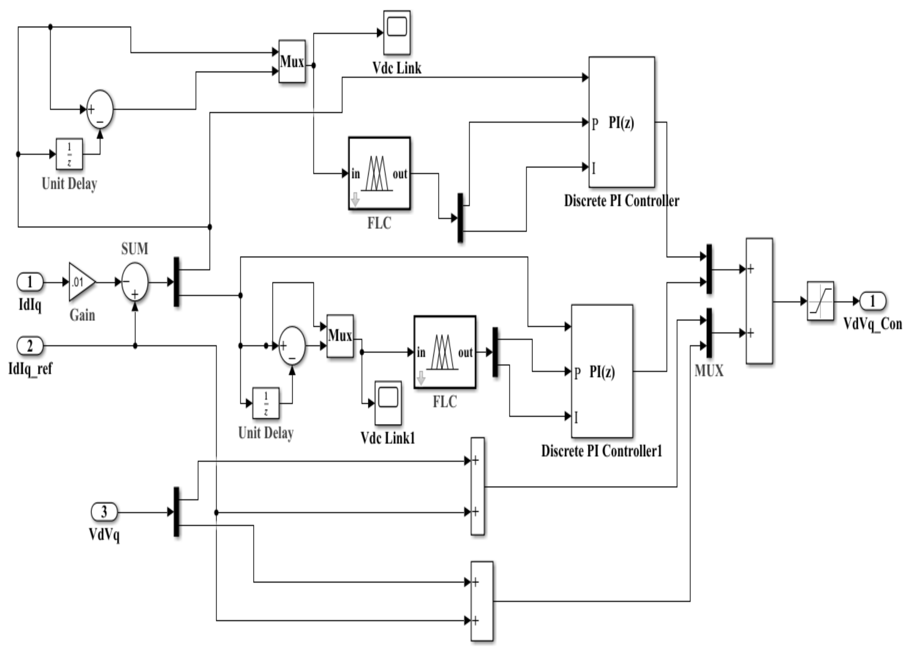
The controller of the inverter consists of a current regulator and a voltage regulator. The internal components of the current regulator are discussed here.
The researchers suggest that the algorithm illustrated in
Figure 2 is a fuzzy-PI controller.
Figure 2 shows the fuzzy-PI controller. First, the Id direct and Iq quadrature currents are subtracted from the Id and Iq reference values to obtain the error. The logic blocks of the fuzzy control the error. The Vd and Vq signals are then added to the controlled signals, which create the control signal to the V
d and V
q direct and quadrature voltages on the complete system. The input of the fuzzy logic is the calculated error that is used to obtain the gains of the PI controller.
On an FLC that is adjusted to the input data is the nonlinear mapping of the output scalar data. FLC consists of three phases: fuzzification, the rules table, and defuzzification [
22]. In most nonlinear applications, the conventional controller does not work well. Therefore, the fuzzy logic control (FLC) was an efficient nonlinear application solution.
Fuzzification is the process that is used to convert the input crisp values into the fuzzy variable values by using input gains and normalized membership functions. Defuzzification is the process that is used to convert the fuzzy variable values into crisp values by using output gains and normalized membership functions.
Two blocks of fuzzy logic are used: one for voltage control and the other for current control. The fuzzy controller design consists of the design of the membership functions and the design of the rules table. By using the Matlab Fuzzy Toolbox, the researcher can build the FLC [
20].
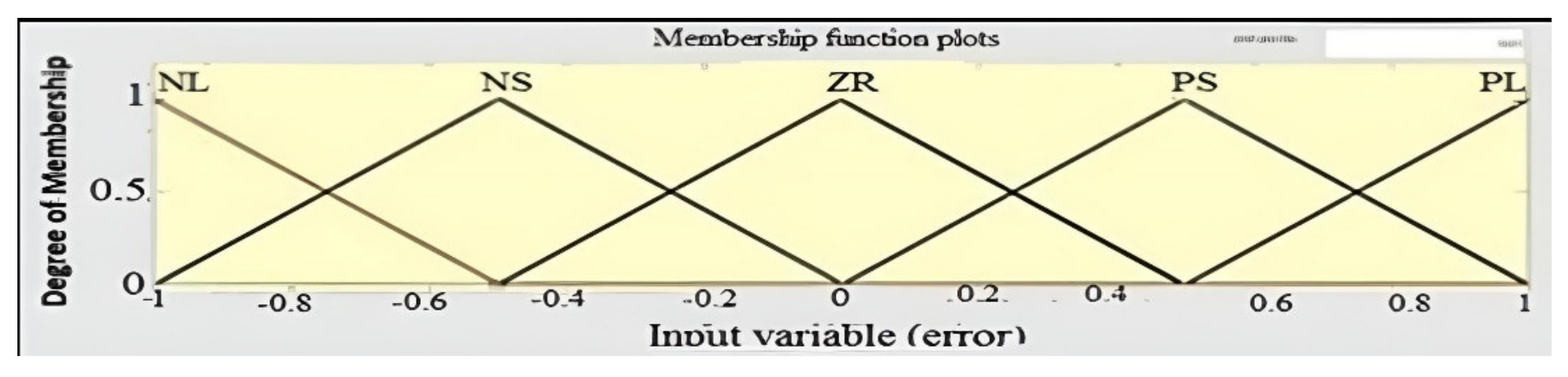
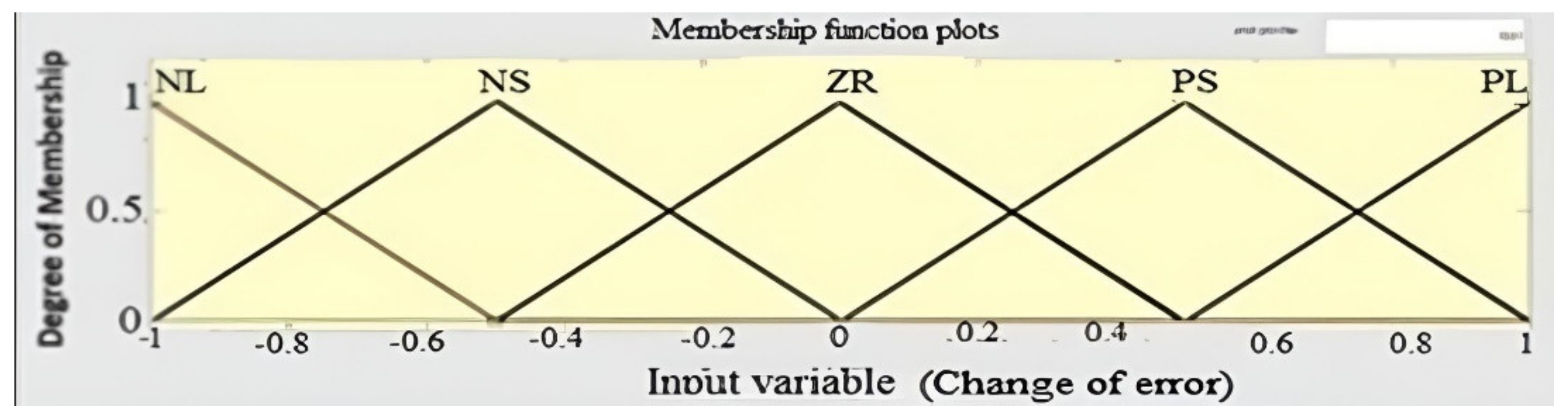
Each fuzzy element in
Figure 3 and
Figure 4 is the meaning of each language connected to five uniform membership functions. Fuzzy logic control is used for tracking currents (Id and Iq), while a phase-locked loop (PLL) is used for park transformation synchronization (ABC-DQ) [
22,
23].
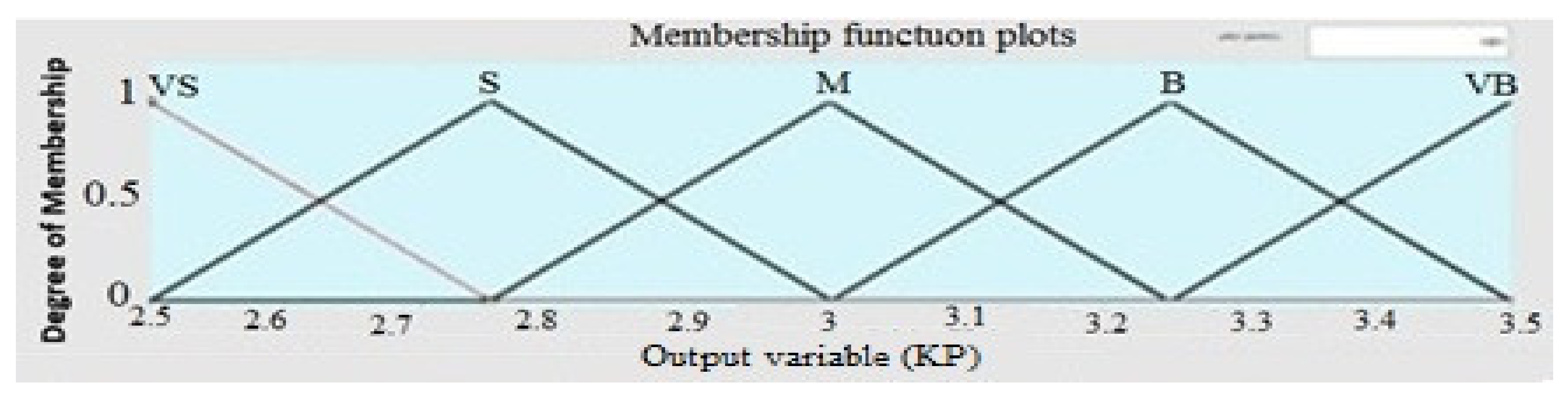
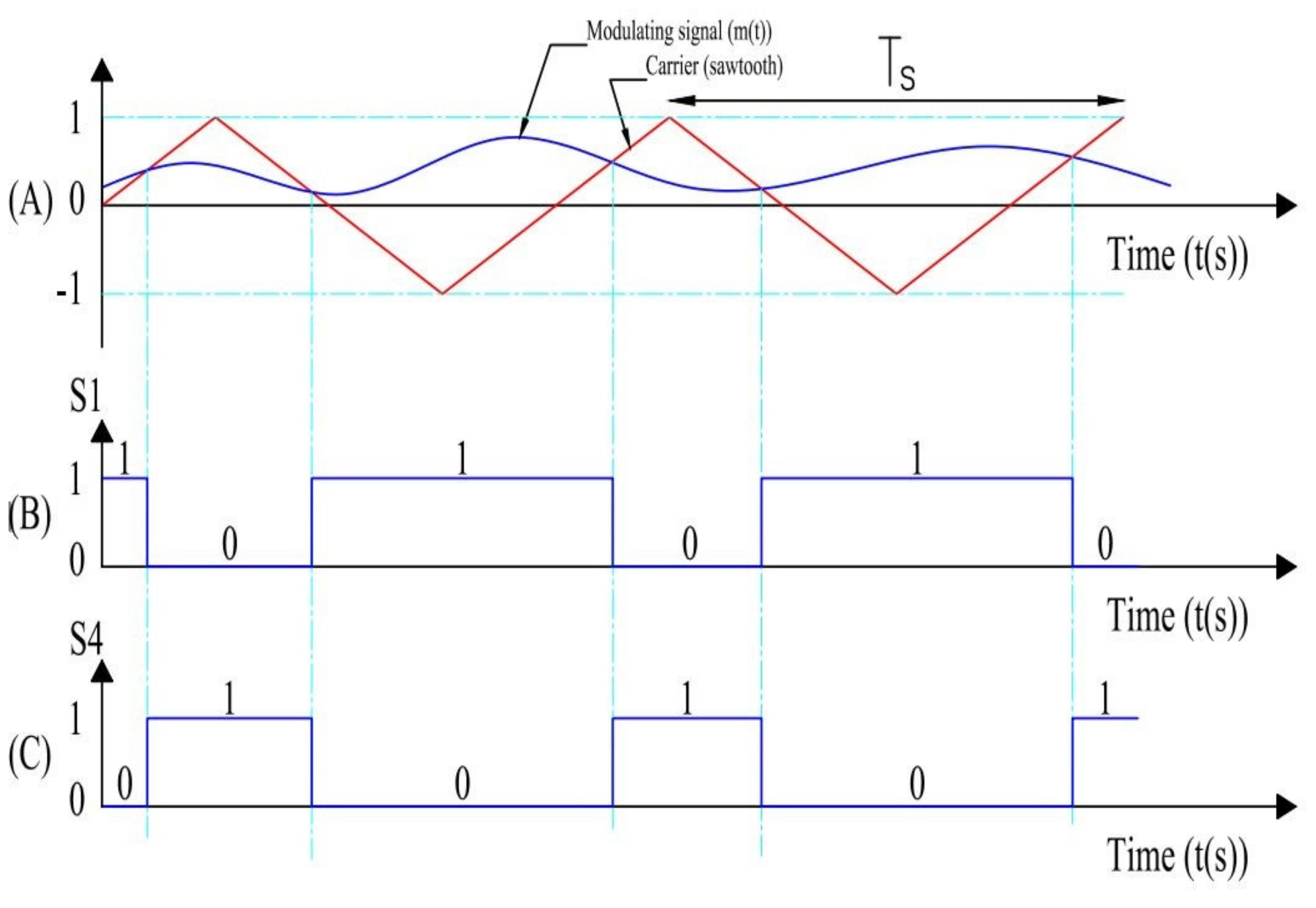
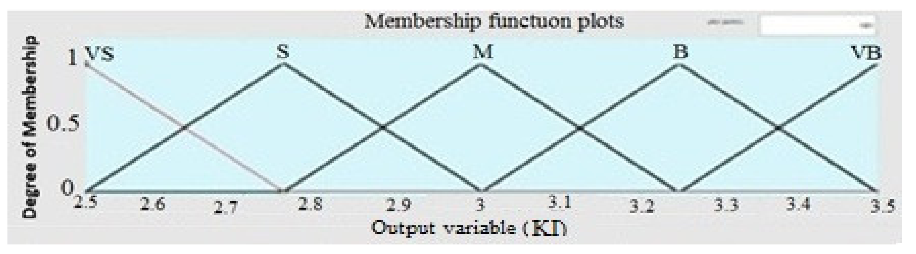
The block of fuzzy logic has two inputs, the change of error (ΔΔe) and the error (Δe) that generates the PI controller gains, which are defined as integral gain (Ki) and proportional gain (Kp). In accordance with variations in the temperature and the irradiance, the proposed fuzzy-PI controller varies gain values (Ki and Kp). The (Ki and Kp) values are multiplied by the error before being passed to the discrete-time integrator and zero-order hold. The membership functions of direct and quadrature Id and Iq output currents for fuzzy inverter control with Ki gain between 14.5 to 15.5 and Kp gain between 2.5 to 3.5 are illustrated in
Figure 5 and
Figure 6, where a rule table is used to minimize the current error and the transient response to perform FLC [
24].
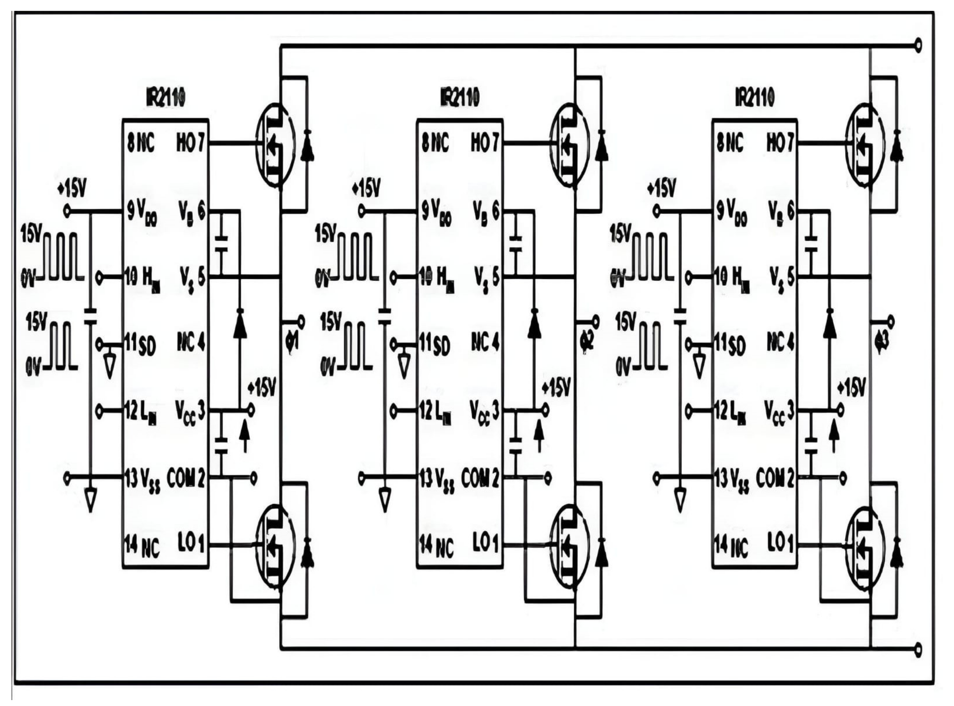
2.3. Inverter
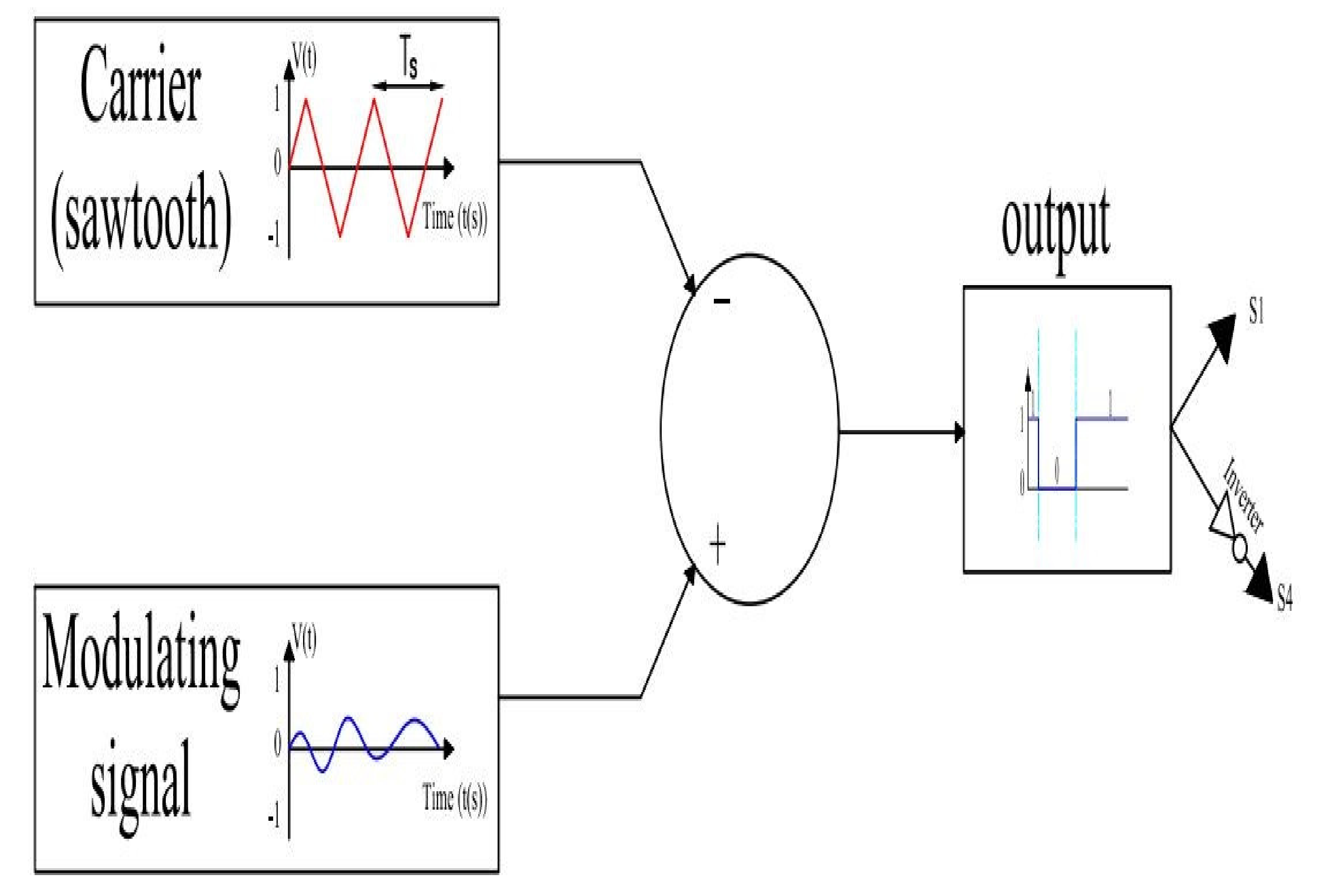
The two-level bridge is connected to a DC power supply.
The bridge output is connected to the three-phase LC filter.
Use a three-phase measurement block after the three-phase LC filter.
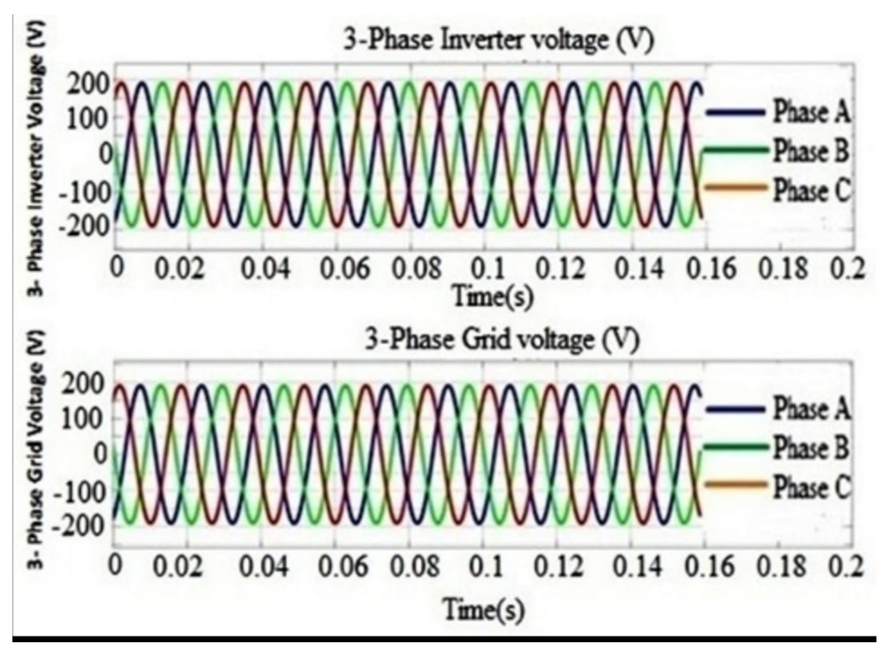
For three-phase voltage and current calculations, a measuring tool is used, as shown in
Figure 1.
Review of inverters in photovoltaic applications [
25]:
Inverters are required to tie PV generators to the utility grid. They convert the DC power generated by PV to AC power used by the grid. Electricity is kept at a constant voltage in only one direction for DC power, and passive filters are usually employed to filter out harmonics generated from the inverter switching, yielding almost a clean voltage with a reduced harmonic distortion, which can be fed into the power grid.
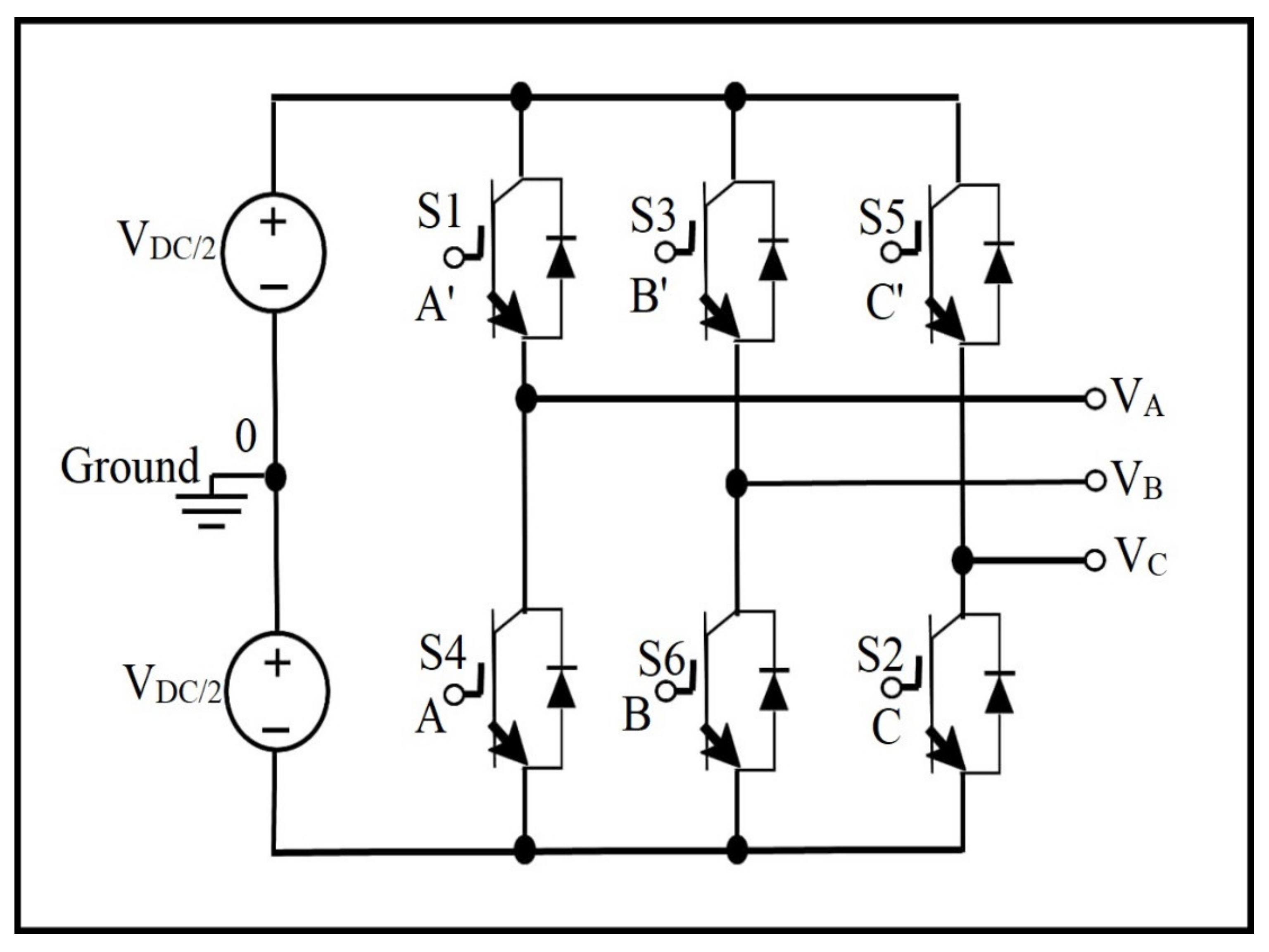
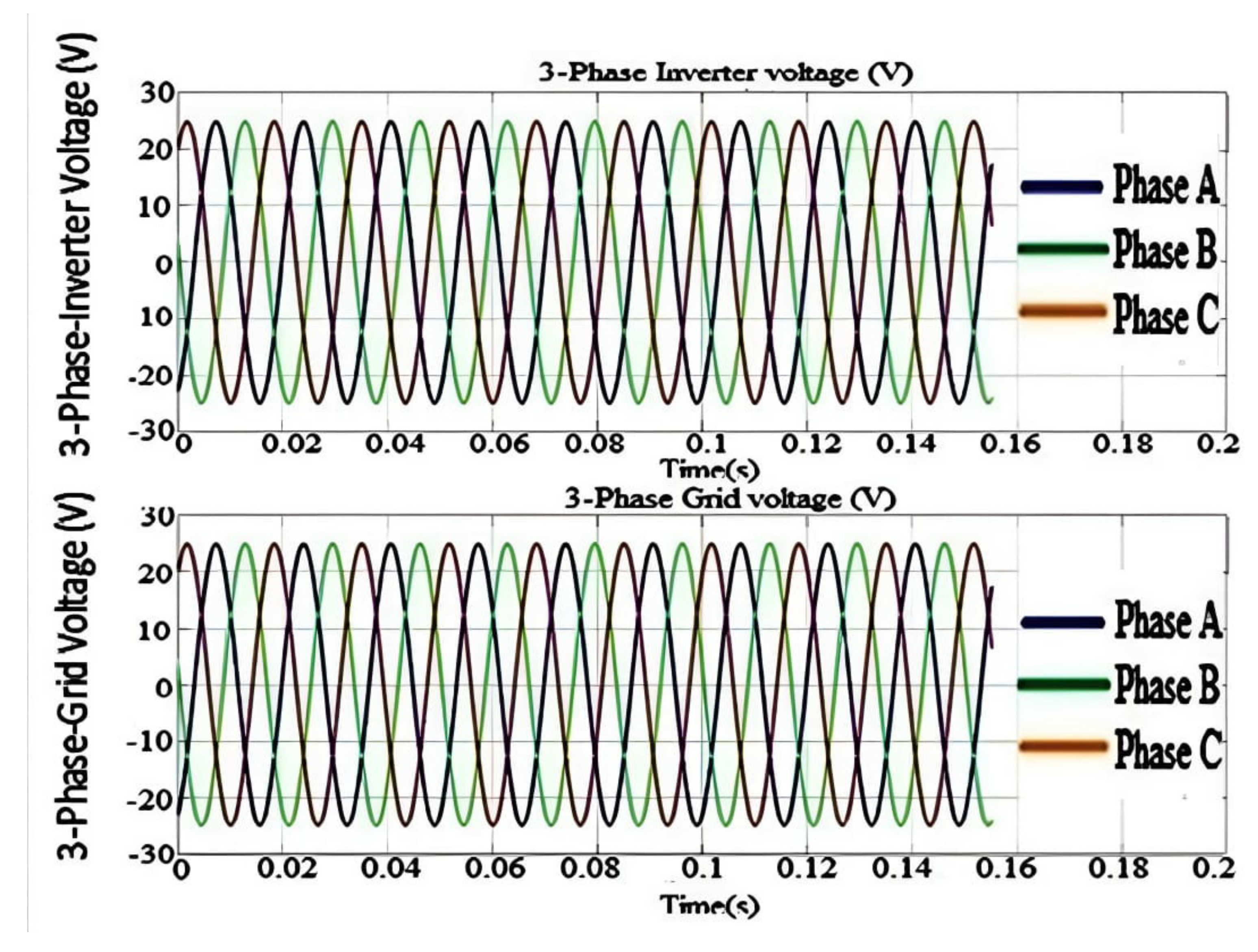
The general-principle diagram of the three-phase inverter and its operating instructions [
26]:
Figure 7 shows three identical half-bridge converters that make up the three-phase, two-level inverter. The DC sides of the three half-bridge converters are connected in parallel to a single DC-side voltage source. Each half-bridge converter has one phase of a three-phase (A, B, and C) AC system wired to its AC-side terminal. The alternating current system could be passive, such as an RLC load, or active, such as a synchronous machine (electrical power grid).
2.4. Three-Phase Loads
In the simulation model, the RLC module is used to model the three-phase load.
The RLC branch is a block with a resistance value (R) related to (active power) and a capacitor (C) and coil (L) related to reactive power. RLC is a Matlab Simulink block of the RLC branch with active load power P = 70 W and reactive load power = 0.
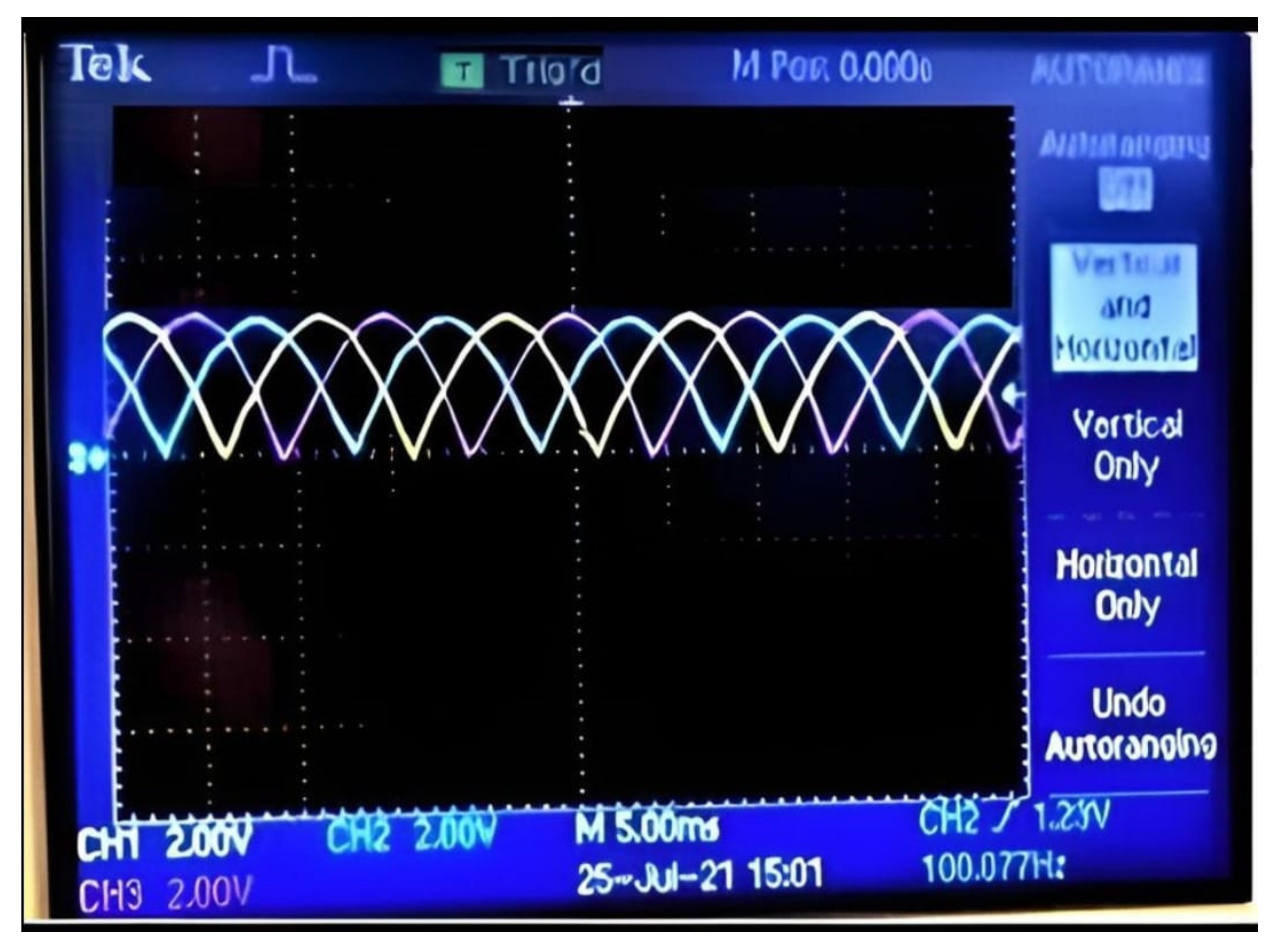
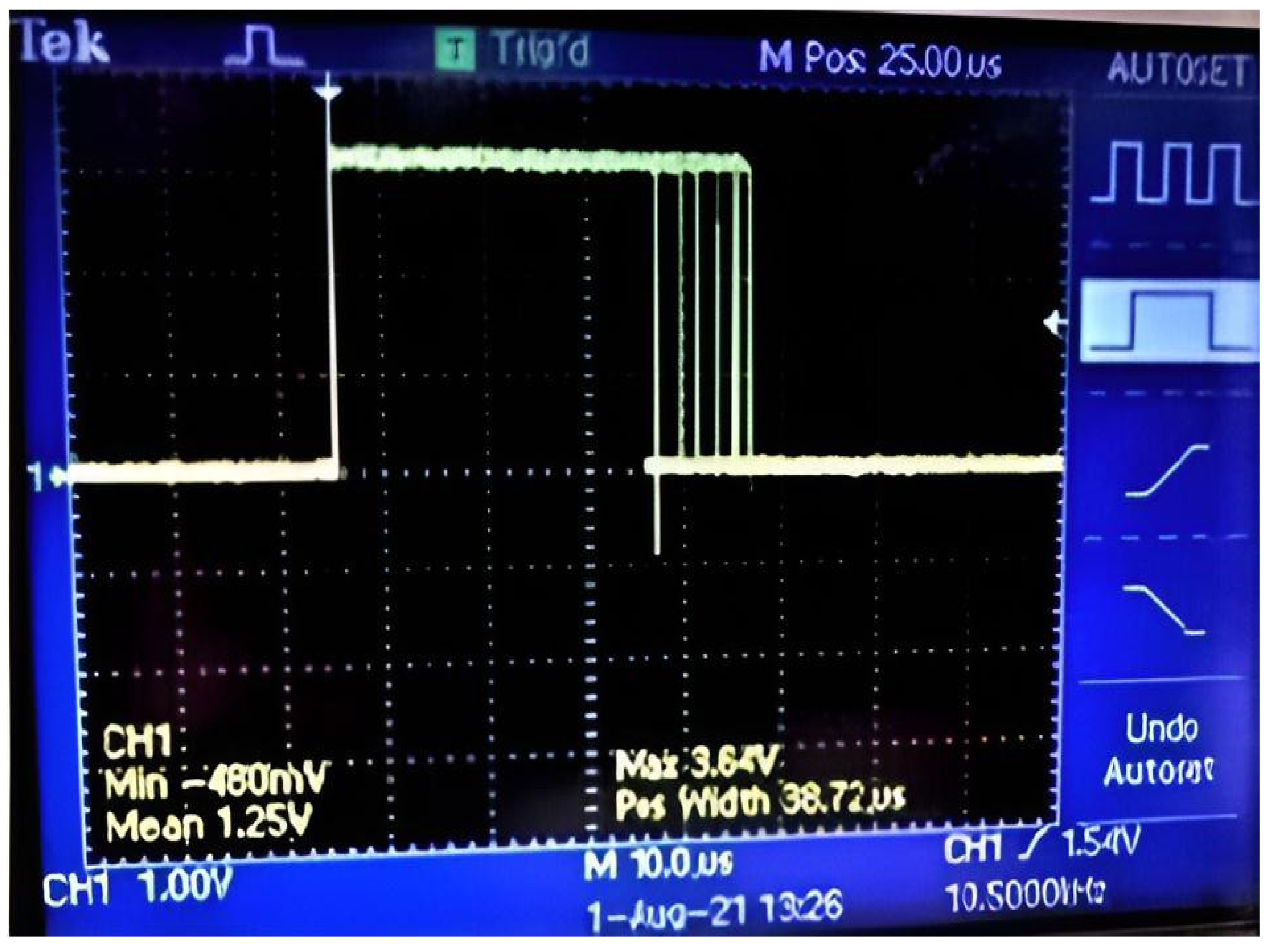
2.5. Total Harmonic Distortion
Total harmonic distortion (THD) is a measure of how a signal (voltage or current) is distorted by the harmonics in the signal.
The main measurement results obtained from Simulink prove that the fuzzy-PI controller works in theory, and then the experimental result is total harmonic distortion.
Simulink uses the THD block to measure the total harmonic distortion of the inverter output signal.


