Article

Simulation Study of Solidification in the Shell-And-Tube Energy Storage System with a Novel Dual-PCM Configuration

School of Engineering, Macquarie University, Sydney, NSW 2109, Australia
*
Author to whom correspondence should be addressed.
Energies 2022, 15(3), 832; https://doi.org/10.3390/en15030832
Submission received: 1 December 2021 / Revised: 18 January 2022 / Accepted: 21 January 2022 / Published: 24 January 2022
(This article belongs to the Special Issue Thermal Energy Storage and Energy Conversion Technologies)

Abstract

:
This study proposes a novel dual-PCM configuration with outstanding solidification response in a horizontal shell-and-tube energy storage system. To demonstrate that the proposed PCM configuration is superior in its thermal responses, results from a range of numerical simulations are presented and compared between different configurations of dual-PCM. As the melting/solidus point is a crucial factor for the solidification rate, dual PCMs are chosen such that the average of their melting point is equal to the melting point of the single-PCM in the reference case. Additionally, equal-area sectors are considered for all cases to ensure the same quantities of PCMs are compared. The temporal liquid fraction and temperature contours reveal that solidification is delayed in the upper half of the system due to strong natural convection motions. Therefore, a dual-PCM configuration is offered to improve the solidification rate in this region and accelerate the full solidification process. Results show that placing a PCM with a lower solidus point in the lower half or an annulus-shaped zone around the cold tube can save the full recovery time up to 8.51% and 9.36%, respectively. The integration of these two strategies results in a novel and optimum design that saves the solidification time up to 15.09%.

1. Introduction

There is a growing environmental concern regarding the increasing usage of fossil fuels, and solar energy has gained much attention as an important substitute [1]. An impending problem with the application of solar energy is that its supply fluctuates with weather conditions. Thermal energy storage (TES) systems have been introduced as an attractive way to store solar energy [2,3]. Three methods of energy storage could be applied in TES systems: sensible (change in the temperature of the storage material), latent (change in the phase of storage material), and chemical (by reversible chemical reactions). Phase change materials (PCMs) are highly used in latent thermal energy storage (LTES) systems due to their high latent energy capacity [3,4,5]. A TES system with PCM can store 5–14 times more energy than a system using suitable storage materials of the same volume [6]. The usage of PCMs has received widespread interest, with clear evidence demonstrating the important roles they have in the storage and recovery of solar energy [7,8], energy savings in buildings [9,10,11], and electronics cooling [12,13].
Although PCMs have high energy storage capacity, their poor thermal conductivity is a major challenge, especially in solidification, where the conduction heat transfer is mainly dominated, and natural convection is less effective. Therefore, novel techniques could be used for an accelerated solidification or melting of the PCMs. Eccentric configuration of the tubes in horizontal TES systems has been identified as an efficient, economical, practical, yet simple technique to improve the rate of phase change process [14]. Senthil [15] experimentally investigated the effect of heat transfer fluid (HTF) tube orientation in a horizontal TES unit filled with PCM. Three types of HTF tube (concentric, eccentric, and inclined) were examined, while water was selected as the HTF with the temperature of 60 °C. The inclined configuration was found to be more efficient due to revealing 21.42% lesser charging duration compared with the regular concentric configuration. In a numerical study, Kadivar et al. [16] investigated the effect of tube eccentricity in a horizontal PCM-based TES unit. They conducted an optimization to find the radial and tangential eccentricities of the inner tube (HTF tube). The optimized geometry improved the charging time up to 7.1 time faster but worsened the discharging time up to 3 times slower than the reference concentric case. Alnakeeb et al. [17] investigated the effects of the inner flat-tube eccentricity of a TES unit on the melting performance of the PCM. They carried out numerical simulations to examine different eccentricities and aspect ratios of the inner flat-tube and discovered that the best melting performance resulted from the circular tube with the smallest eccentricity value. Although some studies have been conducted to improve the melting performance of single PCM in TES systems, to the best of authors’ knowledge, this technique (eccentric configuration of tubes) has not been attempted to improve the energy recovery in a TES unit (which is associated with the solidification rate of PCM).
Furthermore, the use of multiple PCMs with different melting temperatures has been shown to significantly improve the energy storage and recovery process, which has gained increasing attention in recent years [3,12,18,19,20]. However, when a single-PCM is used, the rate of melting or solidification in different regions of the TES is different due to the non-uniform distribution of the natural convection induced vortexes. Thus, a non-uniform distribution of solid–liquid interface and temperature results. Consequently, a weak storage/recovery performance results. Therefore, an optimum configuration of multiple PCMs with different melting temperatures could alleviate this problem. For example, the solidification process is delayed in regions with strong convective motions. Therefore, placing a PCM with a higher solidus point in these regions can help to compensate for the negative effect of natural convection. The benefit of applying multiple PCMs with varying melting points is studied by Farid et al. [21,22]. They discovered an improved thermal response in a TES system when several PCMs with different melting temperatures are housed in cylindrical capsules, compared to a conventional system with a single PCM. In our latest work [12], the advantage of employing multiple PCMs was also reported. It was found that employing a pair of PCMs (n-Eicosane/RT44) results in a better thermal performance of the heat sink than employing only one PCM (n-Eicosane or RT44). Siyabi et al. [23] employed experimental and numerical approaches to investigate the benefit of multiple PCMs for a better heat transfer rate in a shell-and-tube heat exchanger. They reported that the case with multiple PCMs is the best arrangement due to the shorter melting time. Mozafari et al. [3] investigated the effect of different arrangements of dual PCMs in a triplex tube heat exchanger, when subjected to simultaneous charging and discharging. They developed a new dual-PCM design which improved the thermal energy storage and recovery as 37.93%, and 21.06%, respectively, compared with the reference case with single PCM. This performance was also found to be further improved to 76.9% in storage and 32.9% in recovery by adding 3% nanoparticles to the PCMs. Although some researchers have studied multiple PCMs in the TES system, to the best of the authors’ knowledge, there is no reported study to offer an optimum configuration of PCMs for the energy recovery in a horizontal shell-and-tube heat exchanger.
Despite the poor thermal conductivity of PCMs, a common problem in the solidification of some phase change materials (such as salt hydrates, sugar alcohols, and alkanes) is supercooling [24,25]. In supercooling, the PCM solidifies below its typical solidus temperature, limiting its thermal stability in long-term applications. In the present work, paraffin-based PCMs were selected to avoid the supercooling effect during the solidification.
In this study, PCM solidification in a horizontal shell-and-tube heat exchanger was numerically investigated for different dual-PCM configurations for the first time. An annular geometry was preferred for the heat exchanger due to the high surface-area-to-volume ratio. The full solidification time was comparatively investigated for different dual-PCM configurations. This study aimed to develop a new dual-PCM design for improved heat recovery of the TES system. Numerical simulations were carried out to investigate the thermo-fluidic characteristics of the PCMs during solidification. Dual-PCM configurations that yielded faster solidifications were further optimized through parametric studies. This novel design would benefit wide TES applications in industrial waste heat recovery, solar energy utilization, energy saving in buildings, and cold energy storage systems.

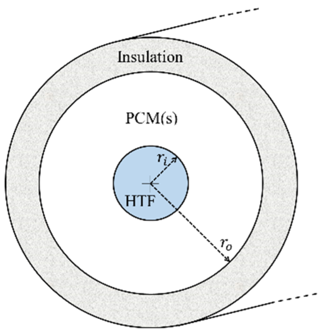
2. Problem Description

Figure 1 shows the schematic of the current storage unit, which includes three concentric copper tubes, where r i = 6.35   mm and r o = 24.13   mm . The HTF passes through the inner tube while the outer tube is insulated. Single PCM or different configurations of dual-PCMs are housed in the middle annulus. The inner tube is assumed to be isothermally cooled with a constant temperature of 300 K. Therefore, the solidification grows initially from a layer around the inner tube. The thermophysical properties of PCMs and the copper tube are summarized in Table 1.
Firstly, simulations were conducted to examine the solidification rate for a different arrangement of dual PCMs (Figure 2). To have a fair comparison, the PCM sectors in all dual-PCM configurations had equal areas. In addition, the selection of PCMs was done such that the effect of other parameters (properties of PCMs) on the comparison results were minimized. For example, the average values of melting temperature and latent heat in dual-PCM cases (PCM-1 and PCM-3) was equal to the melting temperature and latent heat of single-PCM (PCM-2) in the reference case (case-1), as could be seen in Table 1. Furthermore, all the PCMs had the same density of 770 kg/m³, the same thermal conductivity of 0.2 W / m · K , and the same specific heat of 2 kJ / kg · K .

3. Numerical Method

3.1. Initial Boundary Conditions and Assumptions

In this work, a transient 2D model was developed to study the PCM solidification in a shell-and-tube heat exchanger. The natural convection effect inside the liquid PCM was taken into account. The storage unit was considered to be initially fully melted ( T i n i t i a l = 353   K ), which could be expressed as:
t = 0     u r = 0 ,   u θ = 0 ,   T = T i n i t = 353   K
For the symmetric cases (all cases except case-2), only the right-half of the unit was considered in the computational domain. A constant temperature of 300 K was considered for the inner tube, while the outer tube was insulated (zero heat flux). The boundary conditions can be expressed as follows:
r = r i    u r = 0 ,   u θ = 0 ,   T = T C H F T = 300   K r = r o    u r = 0 ,   u θ = 0 ,   T r = 0 θ = ± π / 2      u r θ = 0 ,   u θ = 0 ,   T θ = 0     ( c a s e s 1 ,   3 ,   4 , 5   &   6 )
For the borders between the PCM zones (illustrated with thick dashed lines in Figure 2), the thin wall approximation was applied to allow the heat exchange from one zone to the other. At these boundaries, the temperature was directly mapped by coupling the two sides of each border together as follows:
b o r d e r   w a l l s   { T P C M ( i ) = T P C M ( i + 1 ) u r = 0 u θ = 0
The above equation means that the rate of heat leaving the ( i ) t h PCM layer across the interface is equal to the rate of heat entering the ( i + 1 ) t h layer along the same direction.
In this numerical work, natural convection and heat conduction coexisted during the PCM solidification. The following assumptions were made:
  • The liquid phase was laminar, incompressible, and Newtonian.
  • The radiation heat transfer was not considered in the system.
  • Volume change of PCM during the solidification was neglected.
  • Isotropic and homogeneous materials were considered for the tubes.
  • The HTF was assumed to keep a constant temperature.
  • The thickness of tubes was ignored due to the relatively higher thermal conductivity of the material.
  • Viscous dissipation and slip velocity on the boundaries were ignored.

3.2. Governing Equations

In the present study, continuity, momentum, and energy equations were employed as: (I) Continuity equation
.   V = 0
(II) Momentum equation
ρ ( u r t + V . u r ) = P + μ 2 u r + ρ g sin θ + S u r
ρ ( u θ t + V . u θ ) = P + μ 2 u θ + ρ g cos θ + S u θ
(III) Energy equation
t ( ρ H ) + . ( ρ V H ) = . ( k T )
where h and ΔH represent sensible enthalpy and latent heat, respectively ( H = h + Δ H ) . The term . ( ρ V H ) is the transport of latent-heat evolution. Momentum sink was defined as:
S u r = C ( 1 λ ) 2 u r λ 3 + δ
S u θ = C ( 1 λ ) 2 u θ λ 3 + δ
where C is the mushy zone constant (set to 10 5 in this study), led to the best match with predictions of Khodadadi et al. [27]. δ = 0.001 is a small constant to avoid zero in the denominator. The enthalpy h was defined as:
h = h r e f + T r e f T C p d T
where h r e f is the reference enthalpy at ( T r e f = 273   K ) . Melting heat was calculated based on latent heat L, i.e.:
Δ H = λ L
λ denotes the liquid fraction of PCM during the solidification process, between the solidus and liquidus temperatures ( T s < T < T l . ):
λ = { 0 , T T s T T s T l T s T s < T < T l 1 , T T l
The Boussinesq approximation was used to account for the natural convection motions inside the liquid PCM, considering the variation in density. Thus, the density of liquid PCM could be expressed as:
ρ = ρ m β ( T T m ) + 1
where ρ m indicates the original density of liquid PCM, β is the thermal expansion coefficient, and T m = ( T s + T l ) / 2 . T s and T l are the solidus and liquidus temperatures, respectively.

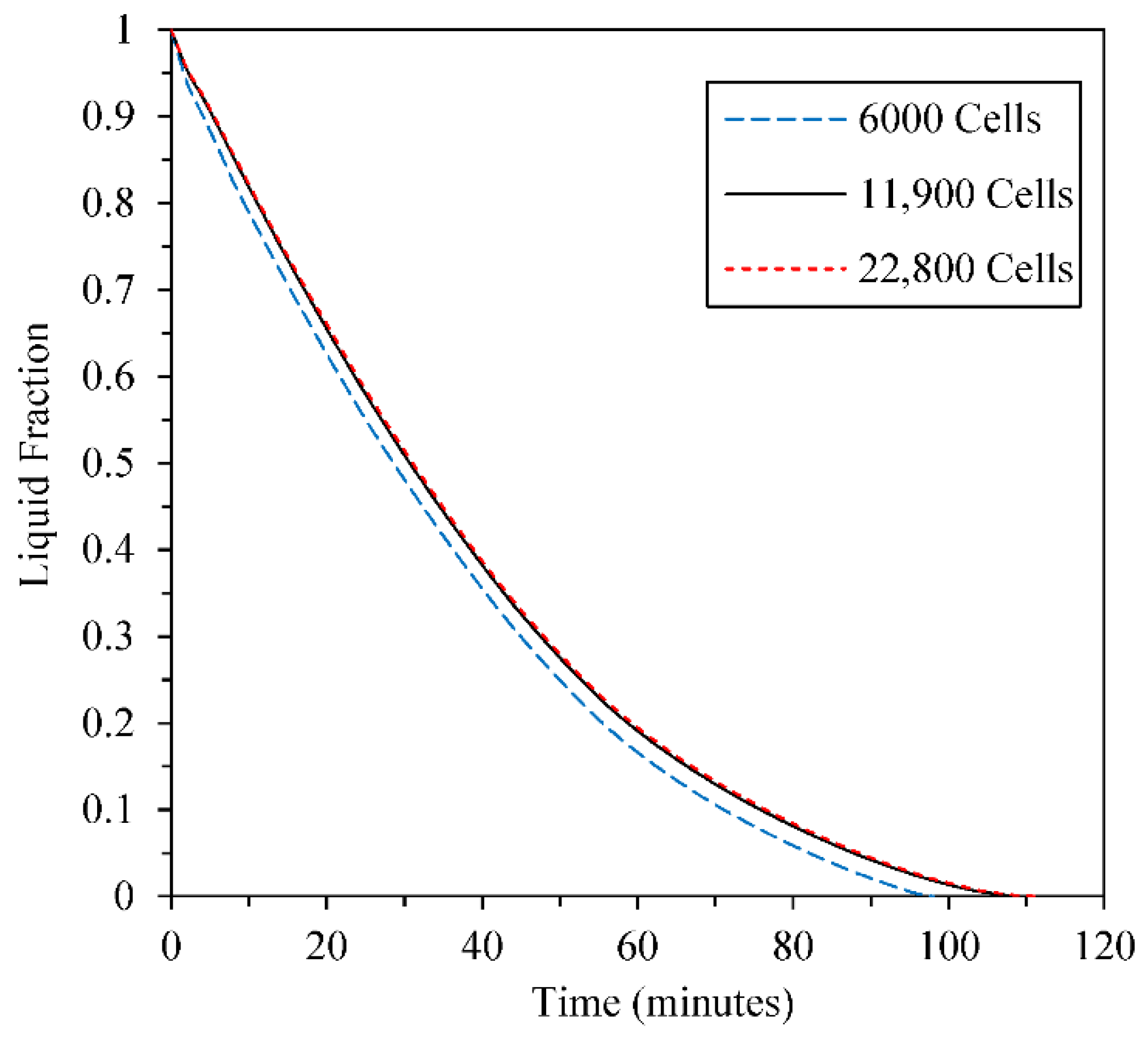
3.3. Numerical Procedure

The current study aimed to predict the solidification of PCM in a shell-and-tube heat exchanger. ANSYS FLUENT 21.1 software was used to conduct numerical simulations. The enthalpy-porosity approach [28] was employed to compute the solidification of PCM, wherein the porosity in each cell was set equal to the liquid fraction in that cell. Finite Volume Method (FVM) was used with high-order quadratic upstream interpolation for QUICK scheme [29] to discretize the governing equations. The pressure-based method was applied to solve the heat and fluid flow equations. The pressure staggering option (PRESTO) scheme was employed for pressure correction during the iterative solution process. The semi-implicit method for pressure linked equations (SIMPLE) algorithm recommended by Patankar [30] was also applied for pressure-velocity coupling. The under-relaxation factors for the momentum, pressure, and energy were set as 0.5, 0.3, and 1, respectively. Convergence criteria for continuity and momentum equations were set as 10 4 , while it was set as 10 6 for the energy.

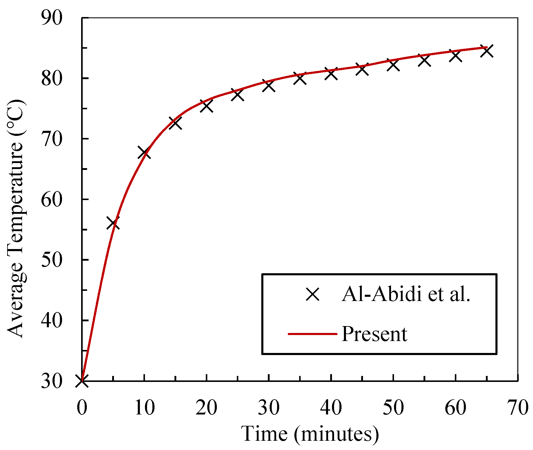
3.4. Validation and Verification

In this section, the simulation method was validated against the experimental reports of Al-Abidi et al. [31]. For this aim, the initial and boundary conditions were set based on the reported data in the reference study [31]. For this validation, the phase change process of paraffin (RT82) was numerically examined in a triplex tube heat exchanger. The comparison plot is illustrated in Figure 3, where a good prediction of temperature during a period of 65 min could be seen.
The effects of mesh size and time-step on the numerical results were thoroughly examined. Figure 4 shows the result of grid independence examination, where transient liquid fraction was predicted for dual-PCM configuration of case-6. Various number of cells (from 6000 to 22,800) were examined in the numerical simulations, and it was observed that increasing the number of cells to higher than 11,900 did not make any significant change in predicted values of liquid fraction. Therefore, computational domains with 11,900 cells were selected for the predictions. The time step was also found to be set to 0.1 s for an accurate prediction.

4. Results and Discussion

Computational Fluid Dynamics (CFD) was employed to examine the heat transfer and fluid flow behavior of PCMs during a heat recovery process in the shell-and-tube heat exchanger.

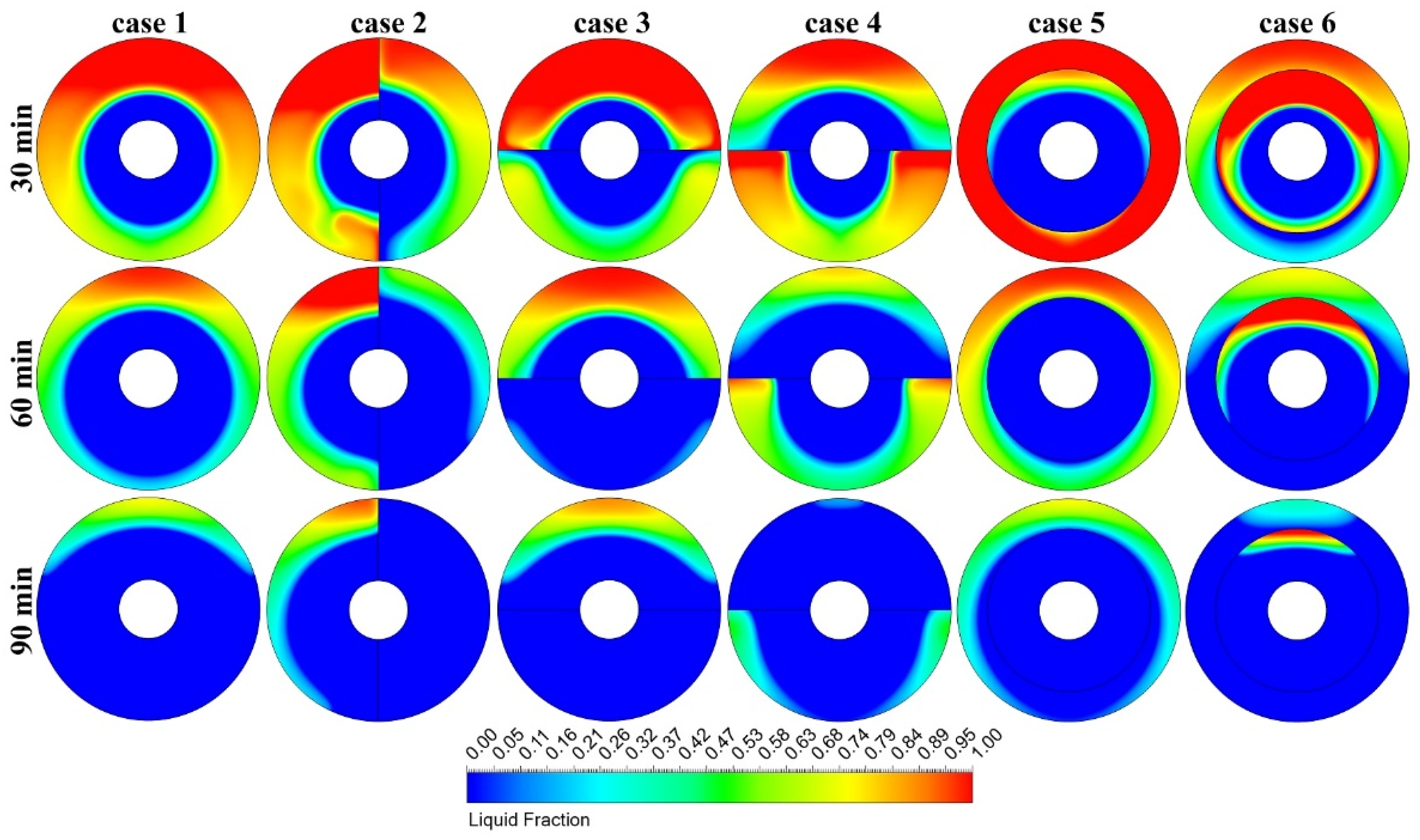
4.1. Comparison of the Configurations

In this section, six cases (refer to Figure 2) were investigated through the discussion on their liquid-fraction and temperature analysis. Next, the configuration with the fastest solidification response was refined with a parametric optimization.

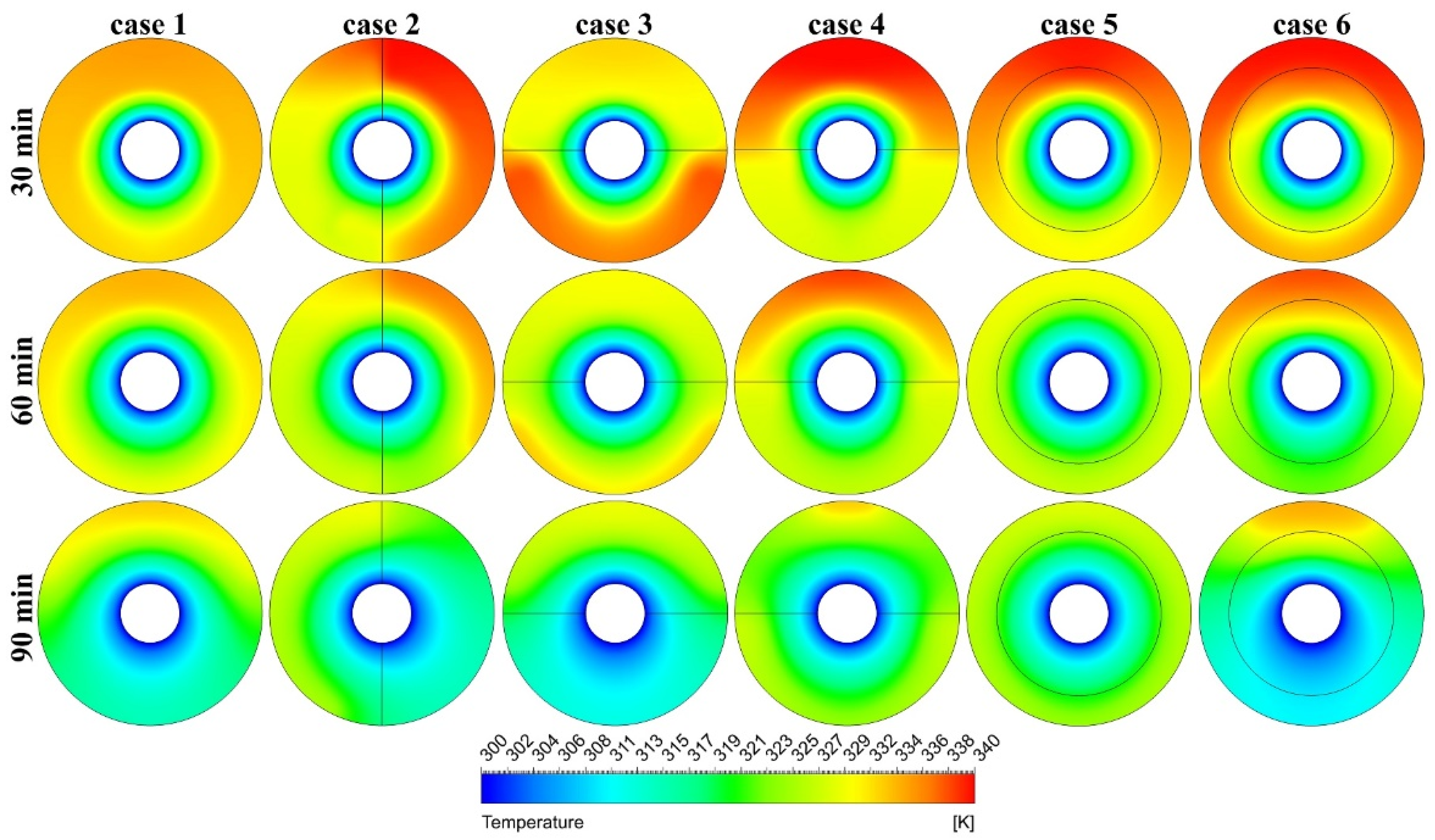
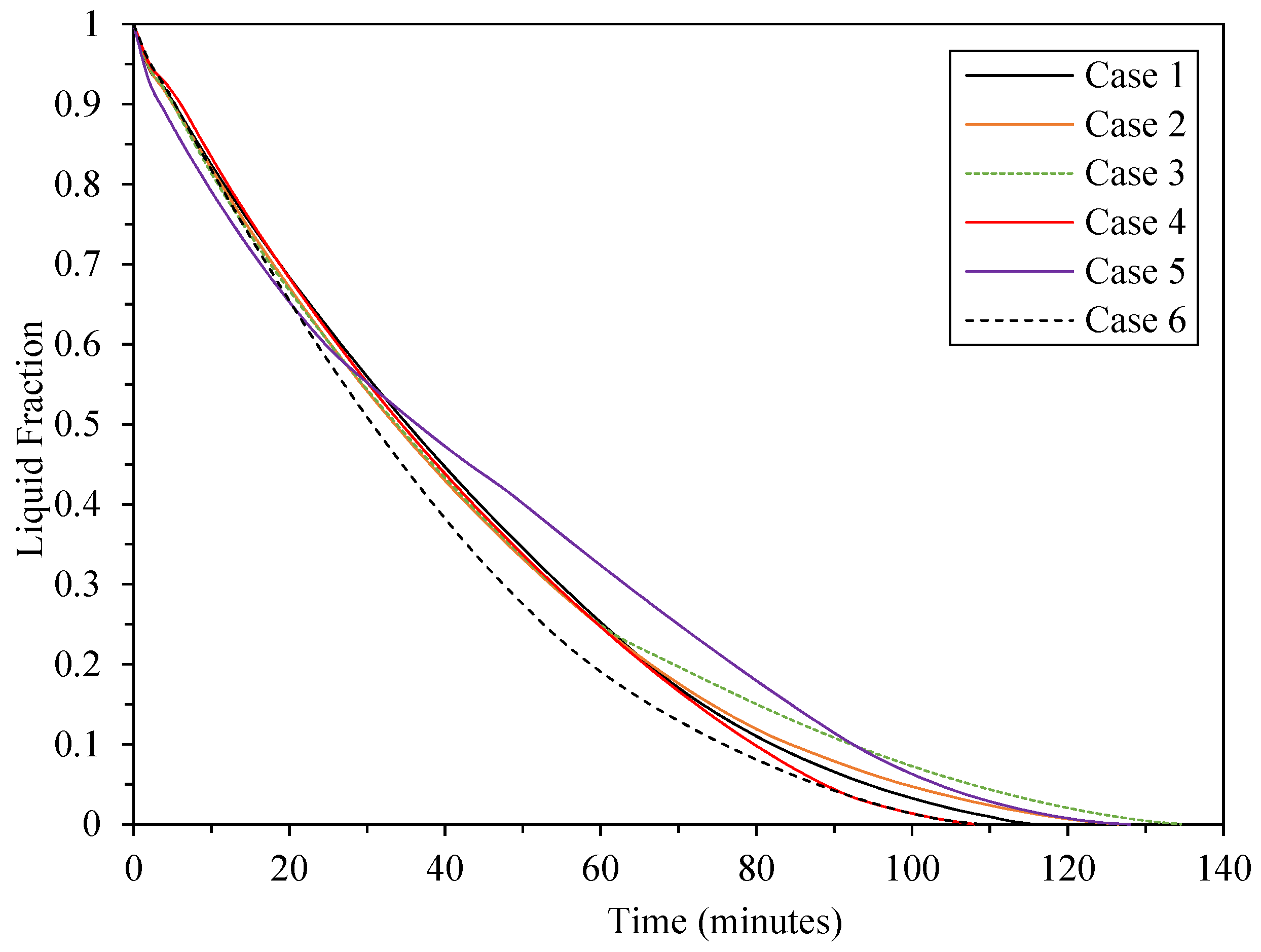
4.1.1. Liquid-Fraction and Temperature Analysis

Figure 5 presents the liquid-fraction contours in three time-stages of discharging of the TES. The evolution of solid–liquid interfaces for all cases indicated that solidification started from the neighbor of the cold inner tube and grew in a radial direction but mostly toward the lower zones. This is due to the strong natural convection induced motions in the upper zone. A buoyancy force drove the hot liquid toward the upper regions since it had a lower density than the cold liquid. Therefore, strong natural convection movements in the upper zone cause delayed solidification in this region. Moreover, a lower range of temperature could be seen in the lower zones of temperature contours illustrated in Figure 6. However, this solidification non-uniformity could be reduced or increased by arranging two different PCMs with different melting-solidification points. Due to higher solidus temperature, PCM-3 showed a faster solidification response than PCM-1 and PCM-2. This could be seen in contour plots of case-2 at Figure 5, where PCMs were housed in left and right sections with the same condition against gravity. Figure 6 reveals that the temperature was mostly changed in layers along the radial direction, indicating the dominance of heat conduction over natural convection, especially in the lower zone.
At the time-stage of 90 min, the liquid fractions of 0.65, 0.079, 0.108, 0.0437, 0.114, and 0.0421 are reported for cases 1–6, respectively. Case-4 and case-6 reveal better solidification responses according to the liquid-fraction evolutions (refer to Figure 5). PCM-3 (which had the quickest solidification response) was housed in the upper half of the unit in case-4. Therefore, the strong natural convection in the upper half was compensated with the quick response of PCM-3 at this zone. As a result, both PCMs fully solidified almost at the same time. Case-6 favored another strategy with the same goal, such that PCM-1 (which had a relatively delayed solidification) was placed around the cold tube and PCM-3 was placed in the outer zone. Therefore, the solidification process finished almost at the same time in both PCMs.

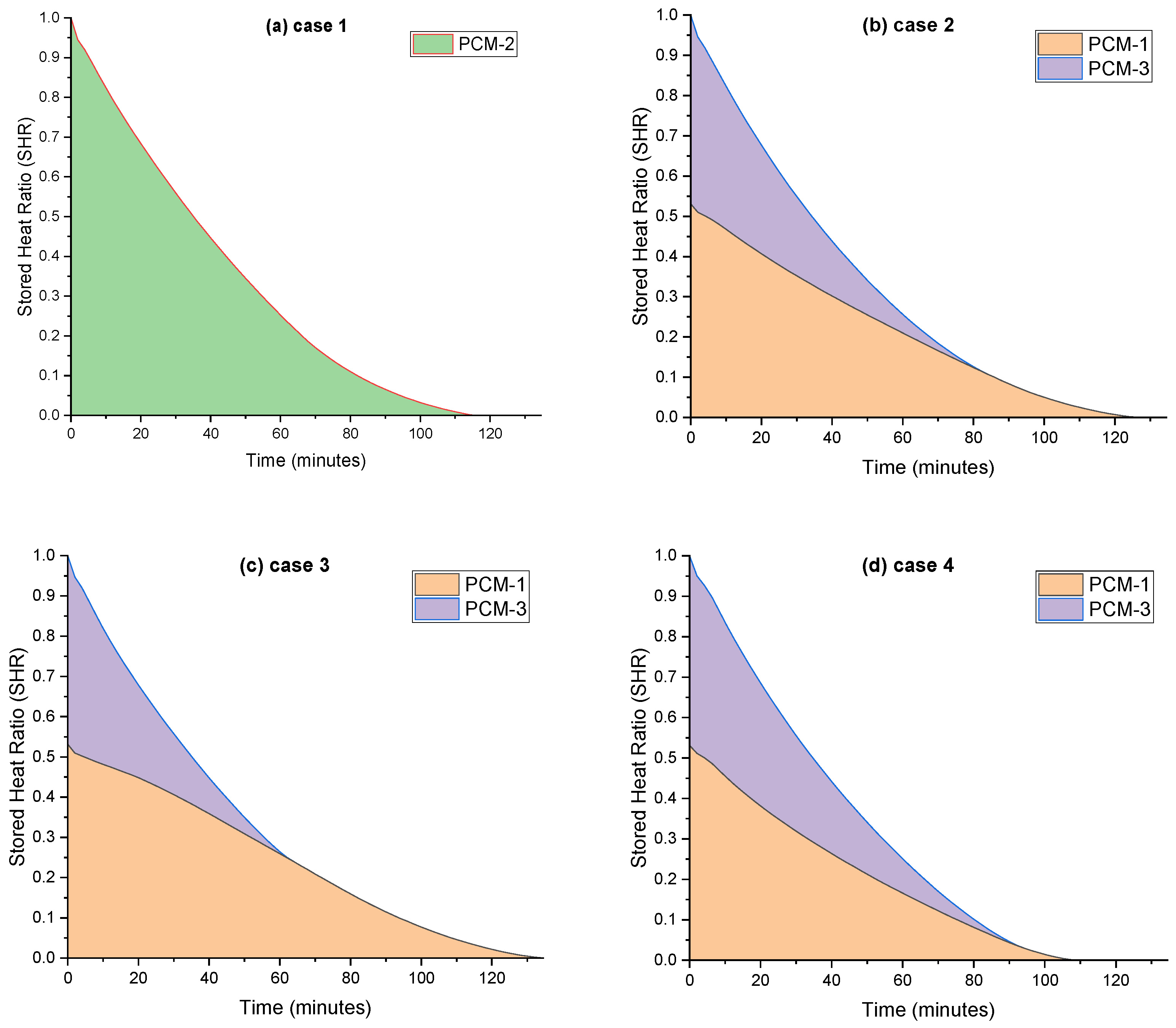
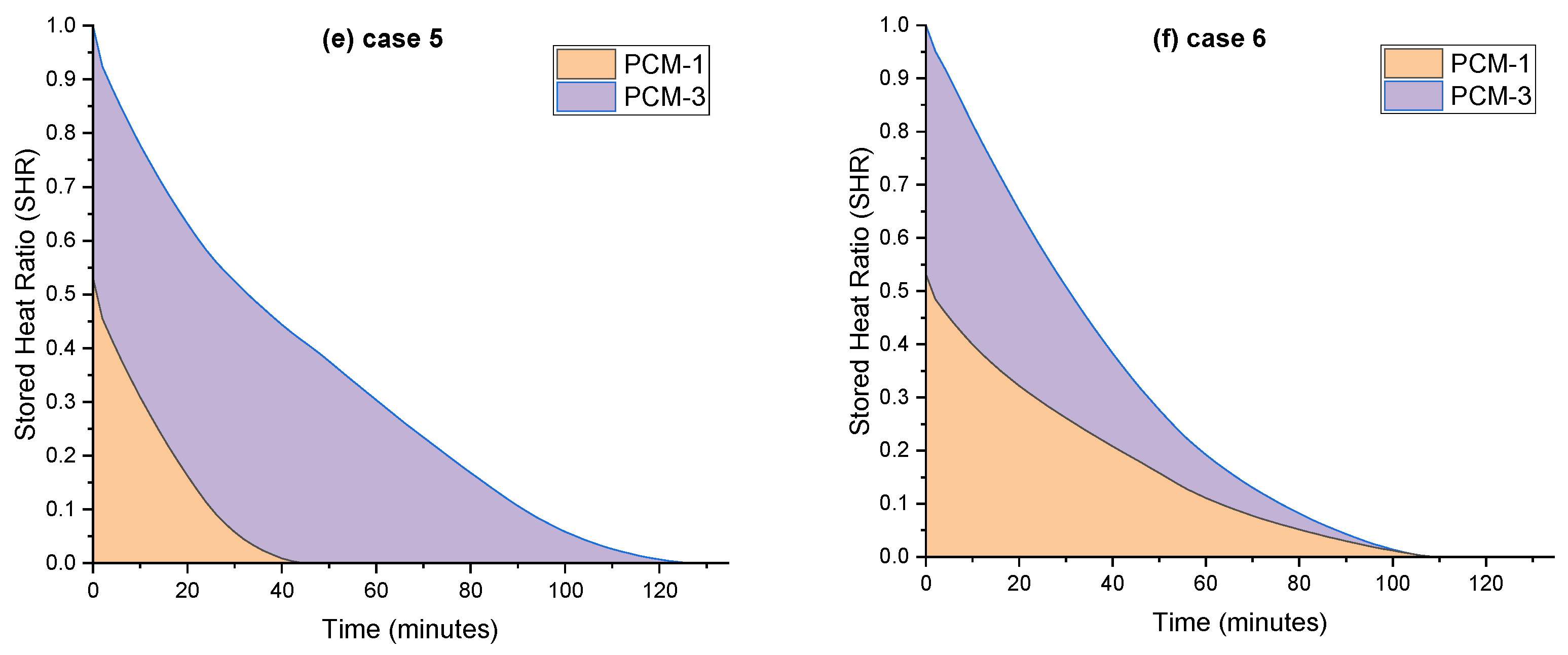
4.1.2. Heat Transfer Analysis

Transient evolution of liquid fraction is presented in Figure 7 for all studied cases so far. For dual-PCM cases, the average liquid fraction of two PCMs were counted. The required time for a full solidification process was found to be 116, 126.5, 134.5, 108, 128, and 109 min for cases 1–6, respectively. Although case-4 revealed the quickest response, Figure 7 shows that case-6 revealed the lowest values of the liquid fraction among the cases most time during the discharging. For example, the liquid fraction of case-6 at time-stages of 30 and 60 min was 0.509 and 0.191, respectively, while case-4 showed higher liquid fractions of 0.553 and 0.247. Figure 7 reveals that the solidification process could be accelerated up to 6.89% or 6.03% when effective configurations of dual-PCM (case-4 or case-6) were preferred over a single-PCM in a shell-and-tube heat exchanger.
Equation (14) expresses the storage heat contribution (SHR) in the TES system, which is the ratio of the latent stored energy to the maximum amount of latent energy that could be stored in the unit:
S H R = L a t e n t   h e a t   s t o r e d   i n   t h e   T E S M a x i m u m   h e a t   s t o r a g e   c a p a c i t y   o f   T E S
Figure 8 shows temporal plots of SHR for all of the studied cases so far. It could be seen that quick, full solidifications could be achieved when both PCMs were almost equally involved in the energy recovery during the whole discharging process (case-4 and case-6). Case-6 revealed the most consistent SHR share of PCMs during the discharging process so that both PCMs went through the solidification process almost equally and were fully solidified with only 4 min time difference. On the other hand, in dual-PCM cases with slow solidification responses (cases 2, 3, and 5), inconsistent solidifications were observed according to the data provided in Figure 8. For example, PCM-1 was fully solidified after 46 min, while PCM-3 was fully solidified after 128 min discharging in case-5.

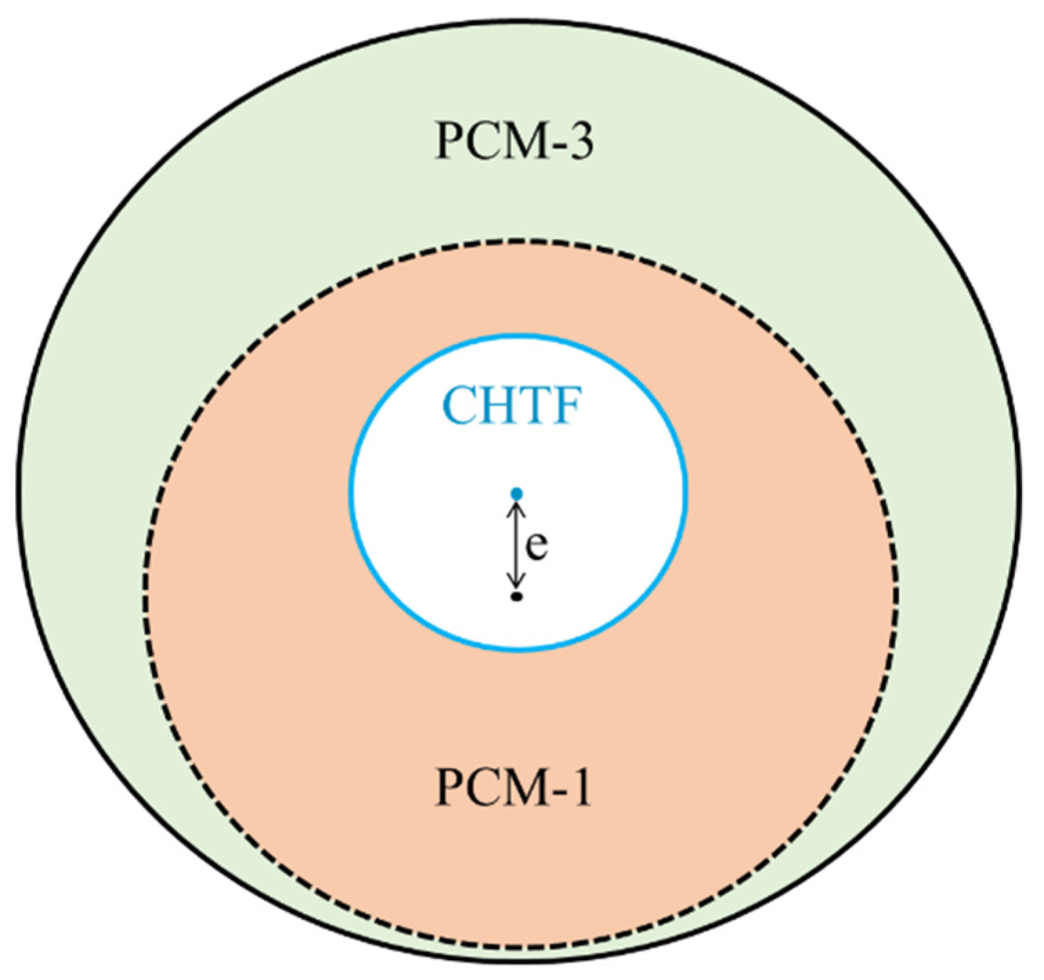
4.2. Optimum Configuration of Dual-PCM

A good TES system should reveal a quick response in storage and recovery of the thermal energy. As discussed in Section 4.1.2, case-4 and case-6 showed better responses in recovering latent heat in the storage unit. Case-6 had the radial distribution advantage where the PCM with delayed solidification (PCM-1) was placed around the cold tube, leading to an almost uniform rate of solidification in both PCMs. On the other hand, housing a quick-solidifying PCM (PCM-3) in the upper half of the unit (where strong natural convection motions prevent a quick solidification) provided an almost consistent recovery in both upper and lower halves. Therefore, two important points must be taken into account for an optimum design of a shell-and-tube system in energy recovery:
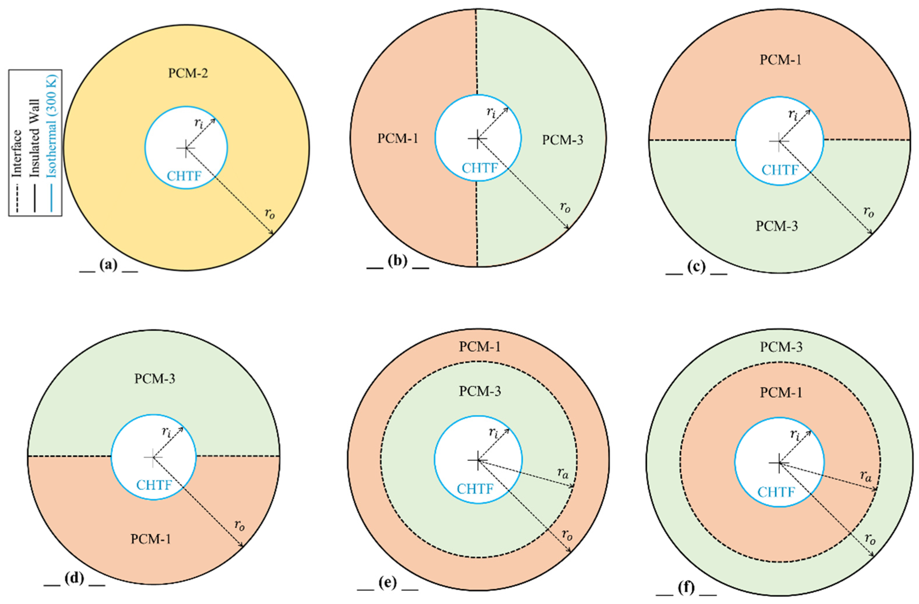
  • Arrangement of PCMs in the radial direction, such that PCM with lower solidus point is placed around the cold tube.
  • Filling the upper half of the unit with the PCM with a higher solidus point.
Considering these points, the configuration of case-6 could be improved if a downward eccentricity is applied for the sector tube (Figure 9). Thus, the optimum eccentricity of the sector tube is suggested in a parametrical study for accelerated energy recovery in the shell-and-tube storage system.
Figure 10 presents the transient reduction in liquid fraction for eccentricities of 3, 4, 5, and 6 mm. A unit with e = 6 mm needs the shortest time (98.5 min) for a full solidification process. It indicates that the new design (case-7: e = 6 mm) accelerates the full solidification process by 15.09% compared with the reference case with a single PCM. The liquid fraction evolution is also compared between cases 1, 4, 6, and 7 in Figure 11. It could be seen that case-7 shows the fastest solidification. The novel design accelerated the solidification time up to 8.51% and 9.36% compared with case-4 and case-6, respectively.
Liquid-fraction and temperature contours at different time-stages are illustrated in Figure 12 for different eccentricities. Only three eccentricities of 0, 3, and 6 mm were selected due to the close similarity of cases. The evolution of contour plots shows that by increasing the eccentricity, a higher portion of PCM-1 (the PCM with delayed solidification) was placed in the lower region, then its delayed solidification was compensated with the advantage of being in the area with weak natural convection. Temporal contour plots clearly show how an eccentricity of 6 mm could improve the solidification rate in both PCMs during the heat recovery process.

4.3. Melting Performance of the New Design

To complement the TES system explored in this study, the new design that shows great reduction in the full solidification time was investigated for melting processes as well. The optimum design was compared with the melting performance of the reference case in order to have a brief evaluation of the heat storage process. For this aim, the HTF with hot constant temperature of 353 K was passed through the inner tube, while the outer tube was thermally insulated. The system was initially kept at a temperature of 300 K. Figure 13 presents the liquid-fraction variation of case-1 and case-7 (optimum design) during the melting process. The full melting times for case-1 and case-7 were reported as 128 and 127 min, respectively, indicating a slight improvement (of 0.8%) in the melting performance of the optimum design.

5. Conclusions

The heat recovery was studied in the solidification of PCMs in a shell-and-tube storage system. Different configurations of dual-PCM were comparatively investigated against a single-PCM configuration. In each dual-PCM configuration, the storage unit was divided into equal-area sections including: left/right sections, lower/upper sections, and annulus-shaped sections. The numerical results show that good arrangements of dual-PCM can improve the energy recovery compared with a traditional unit with a single-PCM. The results can be summarized as follows:
  • Applying dual-PCM configurations instead of a single-PCM configuration does not necessarily improve the solidification performance inside a horizontal TES system, but effective arrangements of PCMs with different solidus points could improve the energy recovery performance.
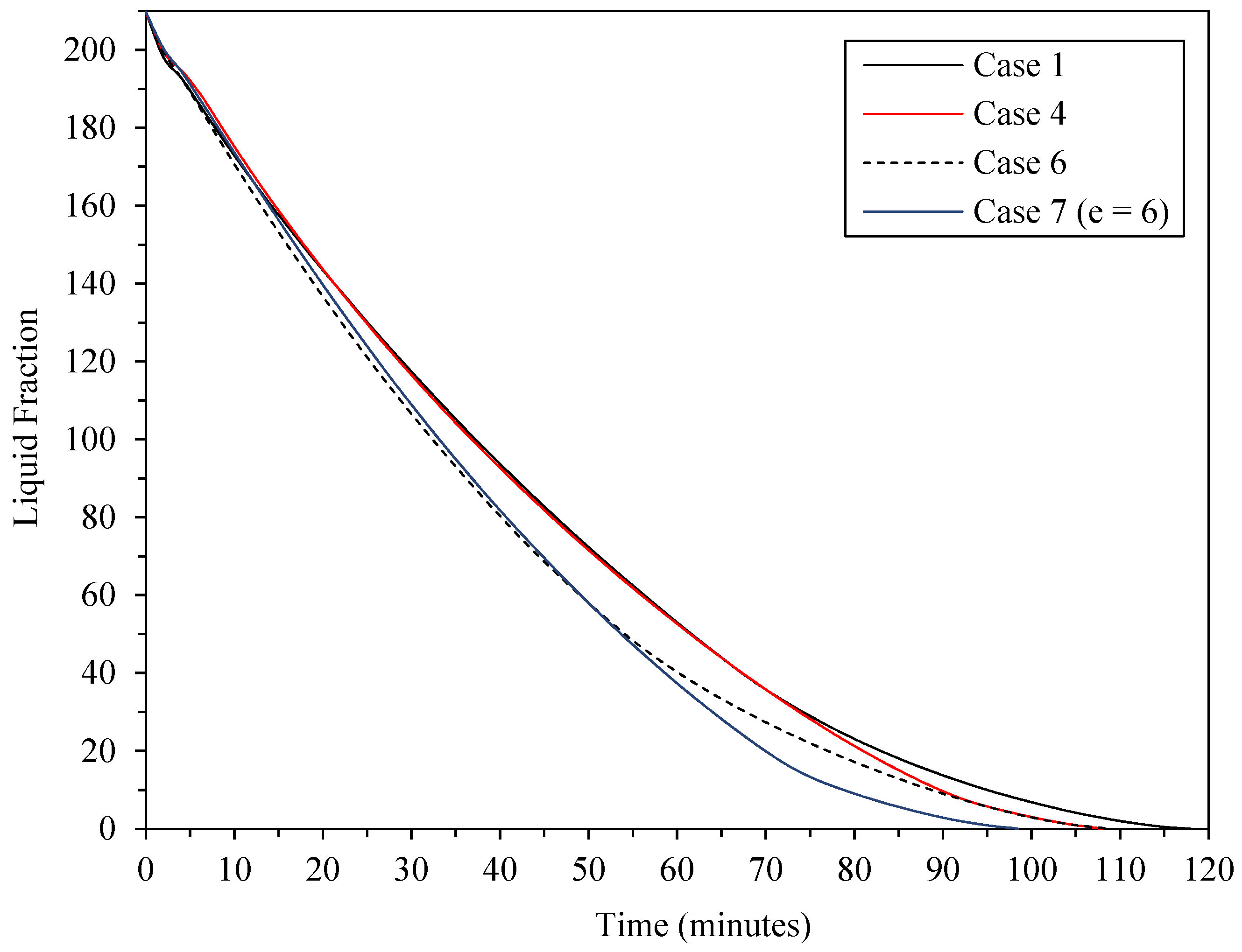
  • Placement of a PCM with a higher solidus point at the upper half and a PCM with a lower solidus point at the lower half of the system could significantly accelerate the solidification time (case-4), up to 6.89% compared with the reference case (case-1 with a single-PCM).
  • When dual-PCMs were radially arranged in the storage unit (annulus-shaped sections) such that the PCM with a lower solidus point is placed around the cold tube (case-6), the energy recovery time improved up to 6.03% compared with the reference case.
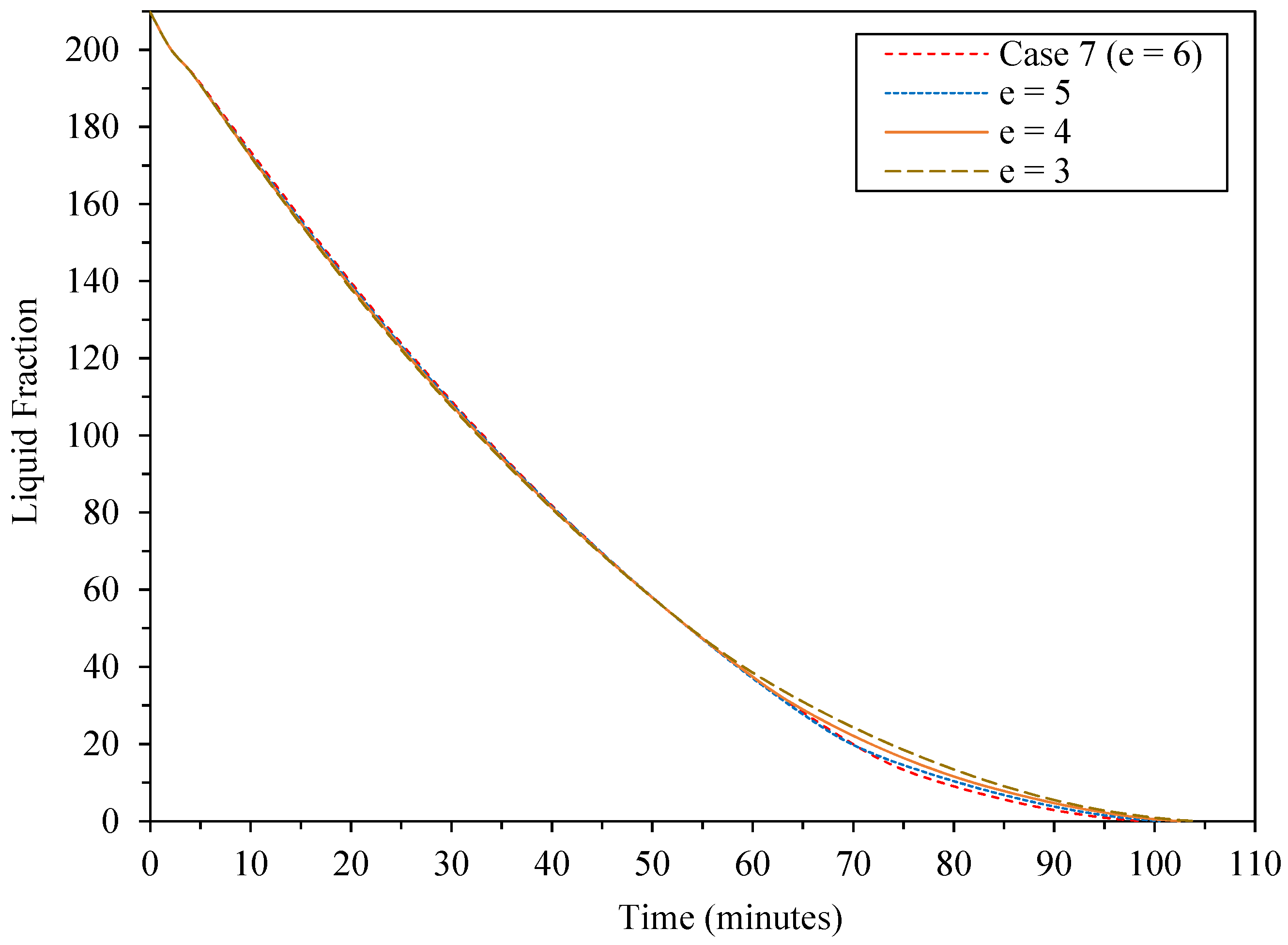
  • A better recovery response in the TES system could be achieved when both design advantages of case-4 and case-6 are taken into account by applying a downward eccentricity to the sector tube of the radial configuration. Therefore, a novel design with 6 mm eccentricity was introduced to accelerate the solidification time up to 15.09%, 8.51%, and 9.36% compared with cases 1, 4, and 6, respectively.
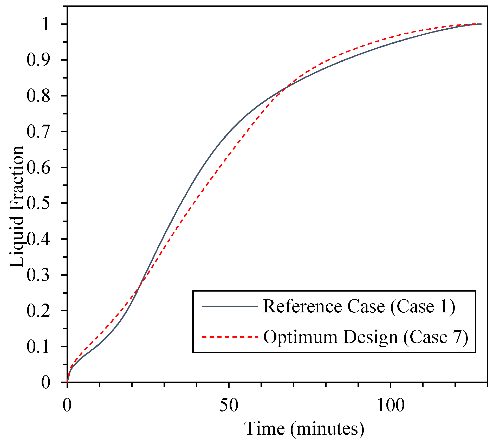
  • Although this paper was focused only on solidification performance of the PCMs in a shell-and-tube storage unit, evaluation of the melting process showed a slight storage improvement for the new design compared with the reference case.
The numerical results in this study are limited to the horizontal shell-and-tube storage units and PCMs used. Such study should be extended to other types of storage containers and further conclusions could be discovered by adding finned structures.

Author Contributions

Conceptualization, M.M.; methodology, M.M.; software, M.M.; validation, M.M.; formal analysis, M.M.; investigation, M.M.; resources, M.M.; data curation, M.M.; writing—original draft preparation, M.M.; writing—review and editing, M.M, S.C. and A.L.; supervision, A.L. and S.C. All authors have read and agreed to the published version of the manuscript.

Funding

This research received no external funding.

Data Availability Statement

Data are contained within the article.

Conflicts of Interest

The authors declare no conflict of interest.

Nomenclature

CMushy zone constant
C p Specific heat (J/kg·K)
dDiameter
gGravity acceleration (m/s²)
hSpecific enthalpy (J/kg)
kThermal conductivity (W/m·K)
LLatent heat of fusion (J/kg)
PPressure (Pa)
SMomentum source term (N/m³)
tTime (s)
TTemperature (K)
T l Liquidus temperature (K)
T s Solidus temperature (K)
uVelocity in r direction (m/s)
vVelocity in θ direction (m/s)
rRadial coordinate
Greek symbols
ρDensity (kg/m³)
βThermal expansion coefficient ( K 1 )
μDynamic viscosity (kg/ms)
θAngular coordinate
δConstant small number
λLiquid fraction
ΦVolume fraction
Subscripts
iInner tube
initInitial
lLiquid PCM
oOuter shell
refReference
sSolid PCM
Acronyms
CFDComputational fluid dynamics
FVMFinite volume method
HTFHeat transfer fluid
LTESLatent thermal energy storage
PCMPhase change materials
PRESTOPressure staggering option
SIMPLESemi-implicit method for pressure linked equations
TESThermal energy storage

References

  1. Kolosok, S.; Bilan, Y.; Vasylieva, T.; Wojciechowski, A.; Morawski, M. A Scoping Review of Renewable Energy, Sustainability and the Environment. Energies 2021, 14, 4490. [Google Scholar] [CrossRef]
  2. Alva, G.; Liu, L.; Huang, X.; Fang, G. Thermal energy storage materials and systems for solar energy applications. Renew. Sustain. Energy Rev. 2017, 68, 693–706. [Google Scholar] [CrossRef]
  3. Mozafari, M.; Lee, A.; Cheng, S. A novel dual-PCM configuration to improve simultaneous energy storage and recovery in triplex-tube heat exchanger. Int. J. Heat Mass Transf. 2022, 186, 122420. [Google Scholar] [CrossRef]
  4. Chaturvedi, R.; Islam, A.; Sharma, K. A review on the applications of PCM in thermal storage of solar energy. Mater. Today Proc. 2021, 43, 293–297. [Google Scholar] [CrossRef]
  5. Tao, Y.; He, Y.-L. A review of phase change material and performance enhancement method for latent heat storage system. Renew. Sustain. Energy Rev. 2018, 93, 245–259. [Google Scholar] [CrossRef]
  6. Ghoneim, A. Comparison of theoretical models of phase-change and sensible heat storage for air and water-based solar heating systems. Sol. Energy 1989, 42, 209–220. [Google Scholar] [CrossRef]
  7. Qiu, L.; Ouyang, Y.; Feng, Y.; Zhang, X. Review on micro/nano phase change materials for solar thermal applications. Renew. Energy 2019, 140, 513–538. [Google Scholar] [CrossRef]
  8. Kumar, A.; Tiwari, A.K.; Said, Z. A comprehensive review analysis on advances of evacuated tube solar collector using nanofluids and PCM. Sustain. Energy Technol. Assess. 2021, 47, 101417. [Google Scholar] [CrossRef]
  9. Saffari, M.; De Gracia, A.; Fernández, C.; Cabeza, L.F. Simulation-based optimization of PCM melting temperature to improve the energy performance in buildings. Appl. Energy 2017, 202, 420–434. [Google Scholar] [CrossRef] [Green Version]
  10. Jia, J.; Liu, B.; Ma, L.; Wang, H.; Li, D.; Wang, Y. Energy saving performance optimization and regional adaptability of prefabricated buildings with PCM in different climates. Case Stud. Therm. Eng. 2021, 26, 101164. [Google Scholar] [CrossRef]
  11. Park, J.H.; Berardi, U.; Chang, S.J.; Wi, S.; Kang, Y.; Kim, S. Energy retrofit of PCM-applied apartment buildings considering building orientation and height. Energy 2021, 222, 119877. [Google Scholar] [CrossRef]
  12. Mozafari, M.; Lee, A.; Mohammadpour, J. Thermal Management of Single and Multiple PCMs based Heat Sinks for Electronics Cooling. Therm. Sci. Eng. Prog. 2021, 23, 100919. [Google Scholar] [CrossRef]
  13. Mozafari, M.; Lee, A.; Cheng, S. Improvement on the cyclic thermal shock resistance of the electronics heat sinks using two-objective optimization. J. Energy Storage 2022, 46, 103923. [Google Scholar] [CrossRef]
  14. Mozafari, M.; Akhavan-Behabadi, M.; Qobadi-Arfaee, H.; Hanafizadeh, P.; Fakoor-Pakdaman, M. Experimental study on condensation flow patterns inside inclined U-bend tubes. Exp. Therm. Fluid Sci. 2015, 68, 276–287. [Google Scholar] [CrossRef]
  15. Senthil, R. Effect of position of heat transfer fluid tube on the melting of phase change material in cylindrical thermal energy storage. Energy Sources Part A Recovery Util. Environ. Eff. 2019, 1–11. [Google Scholar] [CrossRef]
  16. Kadivar, M.; Moghimi, M.; Sapin, P.; Markides, C. Annulus eccentricity optimisation of a phase-change material (PCM) horizontal double-pipe thermal energy store. J. Energy Storage 2019, 26, 101030. [Google Scholar] [CrossRef]
  17. Alnakeeb, M.A.; Salam, M.A.A.; Hassab, M.A. Eccentricity optimization of an inner flat-tube double-pipe latent-heat thermal energy storage unit. Case Stud. Therm. Eng. 2021, 25, 100969. [Google Scholar] [CrossRef]
  18. Gong, Z.-X.; Mujumdar, A. A new solar receiver thermal store for space-based activities using multiple composite phase-change materials. J. Sol. Energy Eng. 1995, 117, 215–220. [Google Scholar] [CrossRef]
  19. Wang, J.; Ouyang, Y.; Chen, G. Experimental study on charging processes of a cylindrical heat storage capsule employing multiple-phase-change materials. Int. J. Energy Res. 2001, 25, 439–447. [Google Scholar] [CrossRef]
  20. Al Siyabi, I.; Khanna, S.; Mallick, T.; Sundaram, S. Multiple phase change material (PCM) configuration for PCM-based heat sinks—an experimental study. Energies 2018, 11, 1629. [Google Scholar] [CrossRef] [Green Version]
  21. Farid, M.M.; Kanzawa, A. Thermal performance of a heat storage module using PCM’s with different melting temperatures: Mathematical modeling. J. Sol. Energy Eng. 1989, 111, 152–157. [Google Scholar] [CrossRef]
  22. Farid, M.M.; Kim, Y.; Kansawa, A. Thermal performance of a heat storage module using PCM’s with different melting temperature: Experimental. J. Sol. Energy Eng. 1990, 112, 125–131. [Google Scholar] [CrossRef]
  23. Al Siyabi, I.; Khanna, S.; Mallick, T.; Sundaram, S. Experimental and numerical study on the effect of multiple phase change materials thermal energy storage system. J. Energy Storage 2021, 36, 102226. [Google Scholar] [CrossRef]
  24. Thonon, M.; Fraisse, G.; Zalewski, L.; Pailha, M. Analytical modelling of PCM supercooling including recalescence for complete and partial heating/cooling cycles. Appl. Therm. Eng. 2021, 190, 116751. [Google Scholar] [CrossRef]
  25. Tan, P.; Lindberg, P.; Eichler, K.; Löveryd, P.; Johansson, P.; Kalagasidis, A.S. Effect of phase separation and supercooling on the storage capacity in a commercial latent heat thermal energy storage: Experimental cycling of a salt hydrate PCM. J. Energy Storage 2020, 29, 101266. [Google Scholar] [CrossRef]
  26. Rubitherm GmbH. Available online: https://www.rubitherm.eu. (accessed on 28 November 2021).
  27. Khodadadi, J.M.; Hosseinizadeh, S.F. Nanoparticle-enhanced phase change materials (NEPCM) with great potential for improved thermal energy storage. Int. Commun. Heat Mass Transf. 2007, 34, 534–543. [Google Scholar] [CrossRef]
  28. Brent, A.; Voller, V.R.; Reid, K. Enthalpy-porosity technique for modeling convection-diffusion phase change: Application to the melting of a pure metal. Numer. Heat Transf. Part A Appl. 1988, 13, 297–318. [Google Scholar]
  29. Leonard, B.P. A stable and accurate convective modelling procedure based on quadratic upstream interpolation. Comput. Methods Appl. Mech. Eng. 1979, 19, 59–98. [Google Scholar] [CrossRef]
  30. Patankar, S. Numerical Heat Transfer and Fluid Flow; Taylor & Francis: Abingdon, UK, 2018. [Google Scholar]
  31. Al-Abidi, A.A.; Mat, S.; Sopian, K.; Sulaiman, M.; Mohammad, A.T. Experimental study of melting and solidification of PCM in a triplex tube heat exchanger with fins. Energy Build. 2014, 68, 33–41. [Google Scholar] [CrossRef]
Figure 1. Schematic of the TES unit in the current study.
Energies 15 00832 g001
Figure 2. Computational domains in the current study; (a) case-1, (b) case-2, (c) case-3, (d) case-4, (e) case-5, (f) case-6.
Energies 15 00832 g002
Figure 3. Validation of the numerical method against the experimental results reported by Al-Abidi et al. [31].
Energies 15 00832 g003
Figure 4. Effect of grid size on the transient liquid fraction in TES with configuration of case-6.
Energies 15 00832 g004
Figure 5. Liquid-fraction contours of the studied cases at different time-stages.
Energies 15 00832 g005
Figure 6. Temperature contours of the studied cases at different time-stages.
Energies 15 00832 g006
Figure 7. Liquid-fraction evolution for studied cases.
Energies 15 00832 g007
Figure 8. Transient variation of SHR for the studied cases.
Energies 15 00832 g008aEnergies 15 00832 g008b
Figure 9. Eccentric configuration of the sector tube.
Energies 15 00832 g009
Figure 10. Transient liquid fraction for different eccentricities of the sector tube.
Energies 15 00832 g010
Figure 11. Comparison of transient liquid fraction between some selected cases.
Energies 15 00832 g011
Figure 12. Histories of liquid fraction (right halves) and temperature distribution (left halves) for different eccentricities.
Energies 15 00832 g012
Figure 13. Melting evolution comparison between the reference case and the new design.
Energies 15 00832 g013
Table 1. Properties of materials employed in this study [26].
Material k   ( W m · K ) C p   ( k J k g · K ) L   ( k J k g ) T s   ( K ) T l   ( K ) ρ   ( k g / m ³ ) β   ( 1 K ) .   μ   ( N · s m 2 )
PCM-1 (RT-55) 0.221703243307700.00050.0264
PCM-2 (RT-60)0.221603283347700.00050.0288
PCM-3 (RT-65)0.221503313387700.00050.03
Copper4000.38---------8920------
Publisher’s Note: MDPI stays neutral with regard to jurisdictional claims in published maps and institutional affiliations.

