1. Introduction
Electrical drives, the main objective of which is a system utilization of electrical machines for electromechanical energy conversion and for control of this transformation, comprise a very important sector of electrical engineering.
At present, variable speed electrical drives with induction motors belong to an industry standard. These drives use two basic techniques to control the magnetic flux and torque: vector control and direct torque control [
1,
2,
3,
4,
5].
For supplying of induction motors, frequency converters with different types of structures and control methods are used [
6,
7].
In general, it is well known that a current control loop of DC or AC drives operates with a steady-state error during the rotor speed transient states, even when proportional integral (PI) current controllers are used [
8]. This error is a problematic issue, especially for fast torque (current) control or time-optimal position control methods, because in these cases, the real motor torque is less than a reference value (steady-state error). This topic is important in the field of traction applications or robotics. In these cases, it is necessary to find methods to suppress the current control error.
Sensorless drives, sensor fault tolerant control and applications of artificial intelligence belong to the top topics in the field of sophisticated control methods for electrical controlled drives. In these cases, the vector control algorithm is mostly used as a basic control method [
9,
10,
11,
12,
13,
14,
15]. This is the reason why it is important to suppress the aforementioned current control steady-state error, to reach the best possible performance of the drive. Equations for the elimination of the coupling between the flux- and torque-producing stator current components are very often used for vector-controlled induction motor drives. The aforementioned coupling occurs in the voltage equations expressed in the rotating reference frame [
x,
y] oriented on the rotor flux space vector. It is well known from the literature [
16,
17,
18,
19,
20] that the decoupling equations are important for independent control of the stator current space vector components. Moreover, the coupling can deteriorate the current responses in the high-speed range if it is not well compensated [
20].
A comparative study of two decoupling control methods, based on the theory of differential geometry and the conventional vector control, is shown in [
21]. In this case, the decoupling between the flux linkage subsystem and the rotor speed subsystem is investigated in different drive operations. A new state equation of an induction motor is proposed in [
22] for easy design of the decoupling system. A robust decoupling current controller is presented in [
18] and is based on an internal model control method. In [
17], a similar decoupling controller was investigated with the goal to be more robust to the parameter variation. Two additional PI controllers in the coupling paths are used in [
19,
20]. If an output voltage vector of the current controllers is greater than the maximum inverter voltage, it is decreased by a reducing technique called overmodulation. In [
20], the overmodulation technique is improved for better torque transient response. All mentioned references are focused on the important issues of the coupling, but this paper deals with the problems concerning the steady-state error of the torque-producing stator current control during the rotor speed changes. The proposed decoupling equations eliminate the steady-state current error. In the paper, a detailed and comprehensive analysis of the problem is presented, including a mathematical description of how the current error can be calculated.
This paper is organized as follows.
Section 2 and
Section 3 deal with the mathematical model of a vector-controlled induction motor and used control structure.
Section 4 focuses on the analysis and compensation of the current control error. Simulation and experimental results are shown in
Section 5 and
Section 6, respectively. Finally, conclusions are presented in
Section 7.
2. Mathematical Model of Vector-Controlled Induction Motor
The vector control of an induction motor is based on the separation of the stator current space vector into two perpendicular components, flux producing
iSx and torque producing
iSy. The components define the magnetization and torque of an induction motor [
4].
The
x-axis of the [
x,
y] rotating reference frame is determined by the position of the rotor flux space vector
ΨR or magnetizing current space vector
im, respectively, (see
Figure 1).
The induction motor model can be described in the different complex reference frames (see
Figure 1).
The following voltage equations can be derived for the components of the stator voltage space vector expressed in the [
x,
y] rotating reference frame:
The following equations can be defined for the induction motor torque and other variables corresponding to
Figure 1:
It is possible to obtain the following equations for the stator current components from the voltage Equations (1) and (2). After the Laplace transformation and by neglecting changes of the magnetizing current, the relations for the stator current space vector components in the
x-axis and
y-axis can be defined as:
Members in square brackets in (14) and (15), respectively, represent undesirable coupling between the x and y components.
The stator current control scheme of the vector-controlled induction motor drive without decoupling block (see
Figure 2) can be drawn on the basis of Equations (14) and (15).
Figure 2 shows the obvious coupling between the flux current component
iSx and the torque current component
iSy according to Equations (14) and (15).
The control scheme shows the current control of both current components without decoupling.
Section 4,
Section 5 and
Section 6 deal with the torque-producing stator current control only, i.e., the influence of the flux-producing stator current
iSx to the torque-producing stator current
iSy only.
To cancel the coupling between the current space vector components, a decoupling block is used. It can be implemented as members that are added to the outputs of the current controllers in the individual axes using the following equations:
For the analysis of the decoupling influence in
Section 4,
Section 5 and
Section 6, the steady-state in terms of excitation is considered (
im =
iSx). In this case, it is possible to derive the following Equations (18) and (19) using Equations (15) and (17):
3. Control Structure of Induction Motor Drive
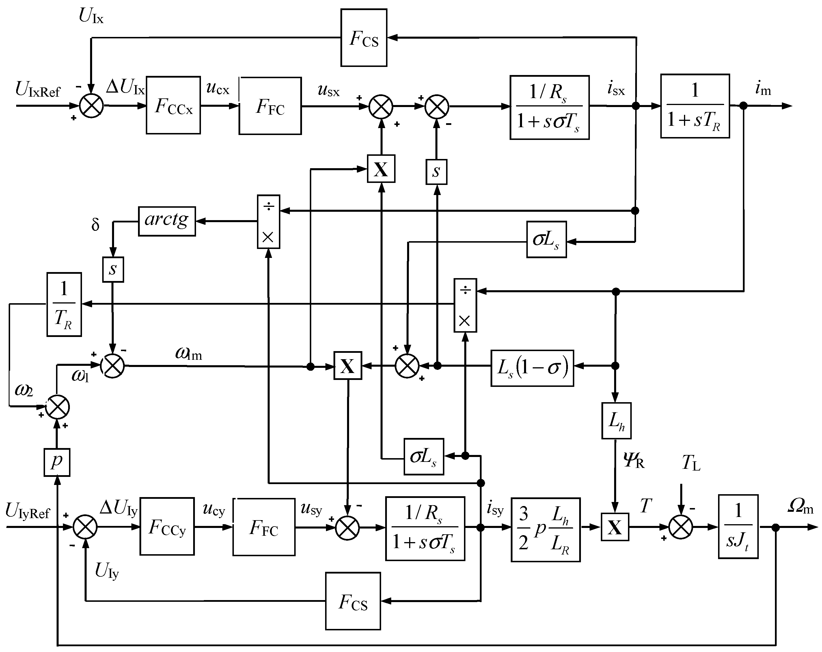
The control structure of the vector-controlled induction motor drive is shown in
Figure 3. The control structure uses the space vectors expressed in the rotating reference frame oriented on the rotor magnetic flux. The current control loops are designed as subordinate loops of the speed and flux (magnetizing current) control.
The estimation of the magnetizing current
im and orienting quantities
sinγ and
cosγ is carried out using the so-called current model of an induction motor (see block Motor model in
Figure 3). This model uses the rotor angle
ε and the rotor time constant
TR for the estimation of the stator current space vector components in the [
α, β] stationary reference frame.
The orienting angle
γ is used for the Park transformation of the complex space vector components from the [
α,
β] stationary reference frame to the [
x, y] rotating reference frame (see block e
− jγ in
Figure 3) and for the reverse transformation (see block e
jγ in
Figure 3).
The reference flux-producing stator current
iSxRef is determined by the PI controller of the magnetizing current, which processes control error between the reference value
imRef and actual value of the magnetizing current
im. The magnetizing current is estimated in the block Motor model (see
Figure 3).
The reference magnetizing current
imRef is constant (nominal) in the operating range from 0 rpm to the nominal speed
ΩmN. The reference magnetizing current
imRef decreases for the higher speeds (field weakening mode) according to the following relation:
In
Figure 3, there is the following description of the blocks:
FC—Frequency Converter; CS—Current Sensor; PWM—Pulse Width Modulation; PS—Position Sensor; ES—Evaluation of Speed; IM—Induction Motor; DEC—Decoupling block.
The reference torque-producing stator current iSyRef is determined by the PI speed controller.
Both components of the stator current space vector are then controlled in the subordinate current control loops. The voltage components ukx and uky are evaluated in the decoupling block DEC according to Equations (16) and (17). They are added to the outputs of the current controllers to suppress the coupling between the x-axis and y-axis.
4. Steady-State Error of Torque-Producing Stator Current Control
For the steady-state error analysis of the torque-producing stator current control, an induction motor drive in a laboratory of the Department of Electronics, VSB—Technical University of Ostrava is considered. The induction motor parameters (type P 112 M04) are shown in
Table 1.
The induction motor is coupled mechanically with a DC machine (type MB 112 S-T) that has the following parameters: PN = 1.5 kW, JDCM = 0.022 kgm2. The total moment of inertia including mechanical coupling is Jt = 0.043 kgm2.
The induction motor is powered by a frequency converter with a voltage source inverter. The DC link voltage Ud = 540 V.
The control of the frequency converter output voltage is based on the sinusoidal pulse-width modulation using a sawtooth voltage with frequency fp = 2 kHz and amplitude Upmax = ±10 V.
The frequency converter gain is defined as KFC = (1/2)·Ud/Upmax = (1/2)·540/10 = 27 and the frequency converter time constant is defined as TFC = 1/(2·fp) = 1/(2·2000) = 0.00025 s = 0.25 ms. The frequency converter transfer function called FFC is treated as a first-order transfer function.
The torque-producing stator current control structure can be created using the following transfer functions:
FCS—current sensor transfer function, current sensor gain KCS = 1 V/A, time constant TCS = 0.5 ms. FCS is treated as a first-order transfer function.
FCCy—torque-producing stator current controller transfer function, current controller gain KCCy = 0.4, time constant TCCy = 8 ms.
FSS—speed sensor transfer function. An incremental sensor IRC 120/1024 is used to measure the rotor speed and position with the four times multiplication of the output pulses. In this case, the number of pulses per one revolution is 4096. The used sampling period for speed evaluation is Tv = 5 ms, so the speed sensor time constant is TSS = Tv/2 = 2.5 ms. The speed sensor gain KSS is assumed to be equal to 1.
For the analysis, the nominal excitation of the induction motor in steady-state is considered (magnetizing current Im = 6 A). This corresponds to the condition im = iSx and the validity of Equations (18) and (19). The influence of the load torque TL, slip angular frequency Ω2 and time derivative of the load angle δ are neglected.
4.1. Torque-Producing Stator Current Control Structure without Decoupling Block
The torque-producing stator current control structures without the decoupling block are shown in
Figure 4 and
Figure 5.
The transfer function
FMy represents the induction motor transfer function in the
y-axis:
The term
Tm in the transfer function
FMy can be regarded as the mechanical time constant. It is calculated for the total moment of inertia
Jt = 0.043 kgm
2, using the motor parameters (see
Table 1), by the following equation:
The term σ
Ts in the transfer function
FMy can be regarded as the electromagnetic time constant:
From
Figure 5, the transfer function of the open control loop for the torque-producing stator current is defined by the following equation:
where the open loop gain
K0 is calculated by:
The steady-state current control error can be calculated according to the following equation:
which represents the steady-state current control error 5.83% of the reference torque-producing stator current for the considered parameters, although the PI controller is used. The main reason for the error is the back electromotive force (EMF) changes caused by the rotor speed transient-states (see
Figure 4 and
Figure 5, respectively). Finally, this is the disadvantage of the torque-producing stator current control structure without the decoupling block. The first one is the well-known coupling between the current space vector components (see
Section 3). The current control error increases with the lower moment of inertia (see Equation (26)).
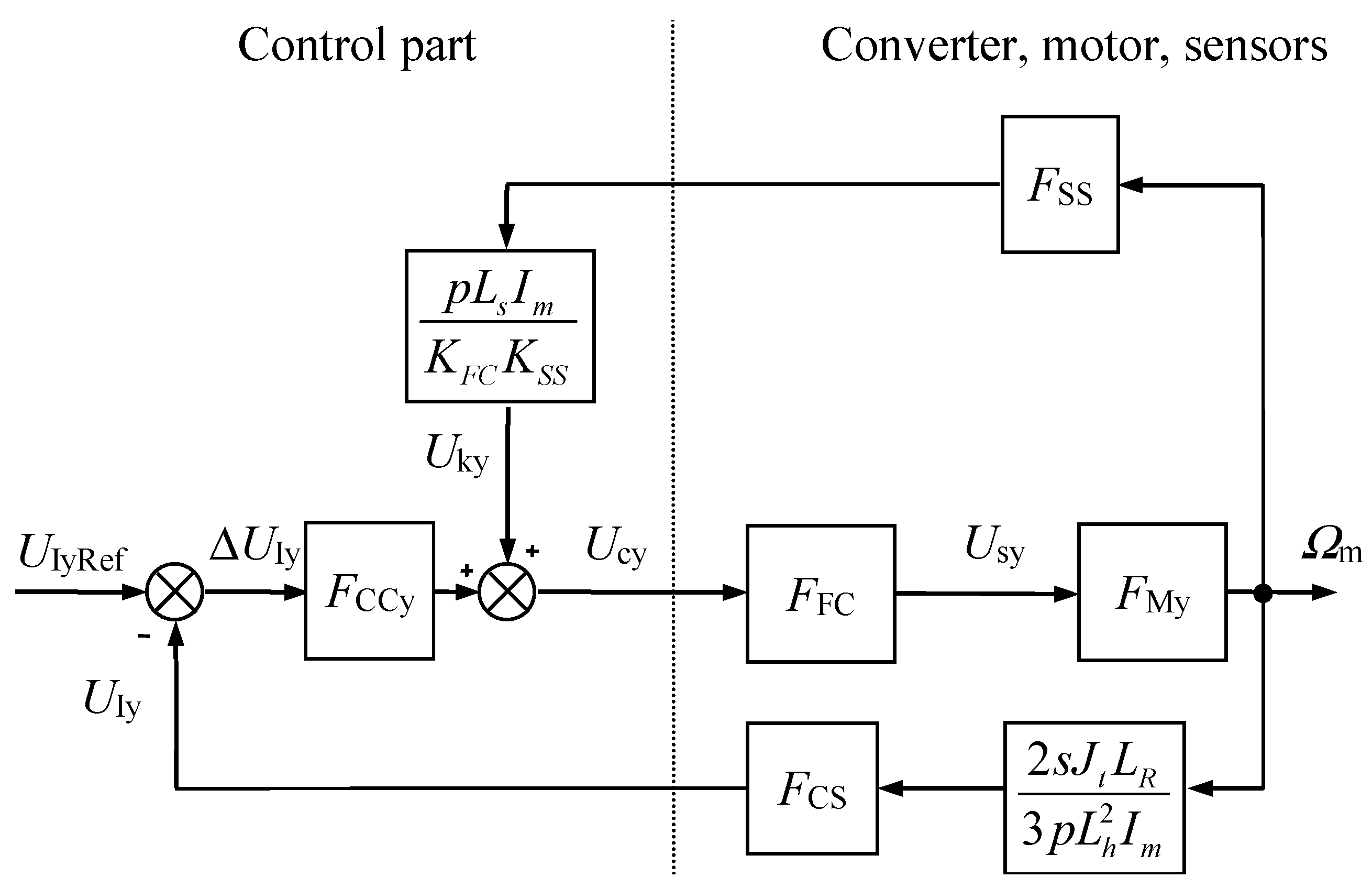
4.2. Torque-Producing Stator Current Control Structure with Decoupling Block
The torque-producing stator current control structures with decoupling block are shown in
Figure 6 and
Figure 7.
From
Figure 6 and
Figure 7, the transfer function of the open control loop with the decoupling block is defined by the following equation:
The steady-state current control error is defined as follows:
In this case, it is evident that the steady-state current error is zero during the rotor speed transient-states.
5. Simulation Results
Models of the presented stator current control structures (
Figure 4 and
Figure 6) were created in the simulation software MATLAB-Simulink.
The actual and reference torque-producing stator currents
iSy and
iSyRef obtained from the control structure without the decoupling block are presented in
Figure 8a,b and with the decoupling block in
Figure 9a,b. The simulation results confirm the derived steady-state current control errors mentioned in
Section 4 for the situation of the rotor speed transient-states (acceleration of the drive).
In the case of the control structure with the decoupling block, the steady-state error is equal to zero (see
Figure 9a,b) which corresponds to (28).
In the control structure without the decoupling block, the steady-state error for the total moment of inertia
Jt = 0.043 kgm
2 is equal to 100·(6–5.65)/6 = 5.83% (see
Figure 8a), which numerically corresponds to the result in accordance with (26). The steady-state error for the total moment of inertia
Jt =
Jm = 0.013 kgm
2 is equal to 100·(6–4.98)/6 = 17 % (see
Figure 8b), which also numerically corresponds to the result in accordance with (29). For this reduced moment of inertia, it is possible to calculate (according to (25)) the open loop gain
K0 = 4.88 against to the original value
K0 = 16.15. In this case, the steady-state current control error is defined by the following Equation (29) using Equation (26):
In
Figure 10a,b, the actual rotor speeds are shown for acceleration of the AC drive with the torque-producing stator currents according to
Figure 8 and
Figure 9. It is evident that the vector-controlled AC drive with the decoupling block provides better dynamic performance.
6. Experimental Results
The presented control structures are experimentally tested on a laboratory stand to verify the theoretical assumptions and the simulation results of the steady-state torque-producing stator current error during acceleration or deceleration of the drive. The laboratory stand consists of the induction motor fed by a voltage source inverter and a Texas Instruments Digital Signal Controller TMS320F28335 based control system.
The same induction motor parameters are used in the simulation stage and the experimental testing (see
Table 1). The vector control method, including the decoupling algorithm, is implemented in the DSC control system with the sampling frequency of 50 μs.
Figure 11a,b shows the experimental results during the acceleration of the IM drive from 0 to 500 rpm and reversal to −500 rpm without the decoupling block (
Figure 11a) and with the decoupling algorithm (
Figure 11b). The IM drive is not subjected to load.
Figure 12a,b shows the experimental results in detail during the acceleration of the IM drive from 0 to 500 rpm without the decoupling block (
Figure 12a) and with the decoupling algorithm (
Figure 12b).
The mentioned steady-state error of the torque-producing stator current control is presented in
Figure 11a and
Figure 12a. The reference torque-producing stator current is 6 A, but the real average value of the torque-producing stator current is 5.2 A.
From
Figure 11b and
Figure 12b, it is evident that the reference and actual steady-state torque-producing stator currents are almost the same, both 6 A. In this case, the control algorithm uses the decoupling block.
The presented experimental results demonstrate better dynamic performance of the control structure with the decoupling algorithm because of a higher torque-producing stator current during the transients of the rotor speed. In this case the acceleration time from 0 to 500 rpm is shorter by about 20 ms.
7. Conclusions
This paper presents that the steady-state error of the torque-producing stator current of the vector-controlled induction motor drive during the rotor speed transient-states can be eliminated using the presented correction decoupling algorithm. The fact was theoretically derived in (28) and confirmed by the simulation and experimental testing.
In the case of the vector control of the induction motor without the decoupling block, the mentioned current error depends on many drive parameters, see (26) and (25), for example, on the frequency converter gain, controller parameters, motor parameters, moment of inertia, magnetizing current etc. In the field weakening region of the drive, it is necessary to take into account the decreasing of the magnetizing current.
The experiment results confirmed the theoretical assumptions and the results from the simulation stage. If the decoupling algorithm is not used and the moment of inertia is 0.013 kgm2, the steady-state torque-producing stator current during the drive acceleration is 4.98 A for the simulation and 5.2 A for the real laboratory model of the drive instead of the reference value equal to 6 A. If the presented decoupling algorithm is used in the vector control structure, the steady-state current error is equal to zero for both the simulation and the experiment too. Of course, the presented decoupling block ensures independent control of the stator current space vector components.
This topic is important in the field of traction applications or robotics. In these cases, it is necessary to find methods to suppress the torque-producing stator current control error.
The above mentioned facts about the steady-state current control error caused by the back EMF changes can be applied with some modifications in other vector-controlled AC drives.
Author Contributions
Conceptualization, M.K., P.P. and D.P.; methodology, M.K. and P.P.; software, M.K. and M.S.; validation, M.K., M.S. and P.P.; formal analysis, M.K.; investigation, M.K., P.P. and D.P.; resources, M.K. and P.P.; writing—original draft preparation, M.K. and P.P.; writing—review and editing, P.P. and M.K.; visualization, M.K.; supervision, P.P. and D.P.; project administration, P.P.; funding acquisition, P.P. and M.K. All authors have read and agreed to the published version of the manuscript.
Funding
This research was funded by the Student Grant Competition of VSB-Technical University of Ostrava, grant number SP2022/48 and by the European Regional Development Fund—Operational Programme Research, Development and Education, grant number CZ.02.1.01/0.0/0.0/17_049/0008425 (Research Platform focused on Industry 4.0 and Robotics in Ostrava agglomeration).
Institutional Review Board Statement
Not applicable.
Informed Consent Statement
Not applicable.
Data Availability Statement
Not applicable.
Conflicts of Interest
The authors declare no conflict of interest.
Nomenclature
| FCCx | x-axis stator current controller transfer function |
| FCCy | y-axis stator current controller transfer function |
| FFC | frequency converter transfer function |
| FCS | current sensor transfer function |
| im | magnetizing current |
| im | magnetizing current vector |
| iSx, iSy | stator current space vector components expressed in [x, y] rotating reference frame |
| Jt | total moment of inertia |
| Lh | magnetizing inductance |
| LR, LS | rotor and stator inductance |
| p | number of pole pairs |
| RR, RS | rotor and stator resistance |
| tE | electromagnetic induction motor torque |
| tL | load torque |
| TR, TS | rotor and stator time constant |
| uSx, uSy | stator voltage space vector components expressed in [x, y] rotating reference frame |
| ε | rotor position angle |
| γ | orienting angle |
| δ | load angle |
| σ | total leakage constant |
| ΨR | rotor magnetic flux |
| ΨR | rotor magnetic flux vector |
| Ω1 | angular speed of stator current |
| Ωim | angular speed of magnetizing current |
| Ωm | electrical rotor angular speed |
References
- Bose, B.K. Global energy scenario and impact of power electronics in 21st century. IEEE Trans. Ind. Electron. 2013, 60, 2638–2651. [Google Scholar] [CrossRef]
- Lisauskas, S.; Udris, D.; Uznys, D. Direct torque control of induction drive using fuzzy controller. Elektron. Elektrotechnika 2013, 19, 13–15. [Google Scholar] [CrossRef][Green Version]
- Aliskan, I.; Gulez, K.; Tuna, G.; Mumcu, T.V.; Altun, Y. Nonlinear speed controller supported by direct torque control algorithm and space vector modulation for induction motors in electrical vehicles. Elektron. Elektrotechnika 2013, 19, 41–46. [Google Scholar] [CrossRef]
- Vas, P. Sensorless Vector and Direct Torque Control; Oxford University Press: New York, NY, USA, 1998. [Google Scholar]
- Perdukova, D.; Palacky, P.; Fedor, P.; Bober, P.; Fedak, V. Dynamic identification of rotor magnetic flux, torque and rotor resistance of induction motor. IEEE Access 2020, 8, 142003–142015. [Google Scholar] [CrossRef]
- Frivaldsky, M.; Dobrucky, B.; Prazenica, M.; Koscelnik, J. Multi-tank resonant topologies as key design factors for reliability improvement of power converter for power energy applications. Electr. Eng. 2015, 97, 287–302. [Google Scholar] [CrossRef]
- Milicevic, D.; Katic, V.; Corba, Z.; Greconici, M. New space vector selection scheme for VSI supplied dual three-phase induction machine. Adv. Electr. Comput. Eng. 2013, 13, 59–64. [Google Scholar] [CrossRef]
- Leonhard, W. Control of Electrical Drives, 2nd ed.; Springer: Berlin/Heidelberg, Germany, 1997. [Google Scholar]
- Girovsky, P.; Timko, J.; Zilkova, J. Shaft sensor-less FOC control of an induction motor using neural estimators. Acta Polytechnica Hung. 2012, 9, 31–45. [Google Scholar]
- Salmasi, F.R. A Self-healing induction motor drive with model free sensor tampering and sensor fault detection, isolation, and compensation. IEEE Trans. Ind. Electron. 2017, 64, 6105–6115. [Google Scholar] [CrossRef]
- Merizalde, Y.; Hernández-Callejo, L.; Duque-Perez, O. State of the art and trends in the monitoring, detection and diagnosis of failures in electric induction motors. Energies 2017, 10, 1056. [Google Scholar] [CrossRef]
- Liu, Y.; Stettenbenz, M.; Bazzi, A.M. Smooth fault-tolerant control of induction motor drives with sensor failures. IEEE Trans. Power Electron. 2019, 34, 3544–3552. [Google Scholar] [CrossRef]
- Listwan, J.; Pienkowski, K. Comparative analysis of control methods with model reference adaptive system estimators of a seven-phase induction motor with encoder failure. Energies 2021, 14, 1147. [Google Scholar] [CrossRef]
- Kuchar, M.; Palacky, P.; Simonik, P.; Strossa, J. Self-tuning observer for sensor fault-tolerant control of induction motor drive. Energies 2021, 14, 2564. [Google Scholar] [CrossRef]
- Tran, C.D.; Palacky, P.; Kuchar, M.; Brandstetter, P.; Dinh, B.H. Current and speed sensor fault diagnosis method applied to induction motor drive. IEEE Access 2021, 9, 38660–38672. [Google Scholar] [CrossRef]
- Lorenz, R.D.; Lawson, D.B. Performance of feedforward current regulators for field oriented induction machine controllers. IEEE Trans. Ind. Applicat. 1987, IA-23, 142–150. [Google Scholar] [CrossRef]
- Briz, F.; Degner, M.W.; Lorenz, R.D. Analysis and design of current regulators using complex vectors. IEEE Trans. Ind. Applicat. 2000, 36, 817–825. [Google Scholar] [CrossRef]
- Harnefors, L.; Nee, H. Model-based current control of ac machines using the internal model control. IEEE Trans. Ind. Applicat. 1998, 34, 133–141. [Google Scholar] [CrossRef]
- Jung, J.; Lim, S.; Nam, K. PI type decoupling control scheme for high speed operation of induction motors. In Proceedings of the 28th Annual IEEE Power Electronics Specialists Conference, St. Louis, MO, USA, 27 June 1997; pp. 1082–1085. [Google Scholar]
- Jung, J.; Nam, K. A dynamic decoupling control scheme for high-speed operation of induction motors. IEEE Trans. Ind. Electron. 1999, 46, 100–110. [Google Scholar] [CrossRef]
- Zhiling, L.; Hongping, J.; Guohai, L. Comparative Study on Vector Control and Differential Geometry Decoupling Control Method of Induction Motor. In Proceedings of the 2005 International Conference on Electrical Machines and Systems, Nanjing, China, 27–29 September 2005; pp. 1539–1543. [Google Scholar]
- Sasakura, Y.; Kawakami, T.; Kawabata, Y.; Ejiogu, E.C.; Kawabata, T. Novel decoupled controller for vector controlled induction motor without rotor constant in the final formula. In Proceedings of the Power Conversion Conference, Osaka, Japan, 2–5 April 2002; pp. 384–389. [Google Scholar]
Figure 1.
Components of stator current space vector.
Figure 1.
Components of stator current space vector.
Figure 2.
Stator current control scheme of vector-controlled induction motor without decoupling block.
Figure 2.
Stator current control scheme of vector-controlled induction motor without decoupling block.
Figure 3.
Vector-controlled induction motor drive.
Figure 3.
Vector-controlled induction motor drive.
Figure 4.
Torque-producing stator current control structure without decoupling block.
Figure 4.
Torque-producing stator current control structure without decoupling block.
Figure 5.
Adjusted torque-producing stator current control structure without decoupling block.
Figure 5.
Adjusted torque-producing stator current control structure without decoupling block.
Figure 6.
Torque-producing stator current control structure with decoupling block.
Figure 6.
Torque-producing stator current control structure with decoupling block.
Figure 7.
Adjusted torque-producing stator current control structure with decoupling block.
Figure 7.
Adjusted torque-producing stator current control structure with decoupling block.
Figure 8.
Simulation results: reference (green) and actual (blue) torque-producing stator current without decoupling; (a) total moment of inertia Jt = 0.043 kgm2 (including DC machine), steady-state value of torque-producing stator current is 5.65 A; (b) total moment of inertia Jt = JM = 0.013 kgm2 (induction motor only), steady-state value of torque-producing stator current is 4.98 A.
Figure 9.
Simulation results: reference (green) and actual (blue) torque-producing stator current with decoupling; (a) total moment of inertia Jt = 0.043 kgm2 (including DC machine), steady-state value of torque-producing stator current is 6 A; (b) total moment of inertia Jt = JM = 0.013 kgm2 (induction motor only), steady-state value of torque-producing stator current is 6 A.
Figure 10.
Simulation results: (
a) actual rotor speed for torque-producing stator current without decoupling according to
Figure 8a (blue) and with decoupling according to
Figure 9a (green), total moment of inertia
Jt = 0.043 kgm
2 (including DC machine); (
b) actual rotor speed for torque-producing stator current without decoupling according to
Figure 8b (blue) and with decoupling according to
Figure 9b (green), total moment of inertia
Jt = 0.013 kgm
2 (induction motor only).
Figure 11.
Experimental results: acceleration from 0 to 500 rpm and reversal, actual rotor speed (light blue), the reference (dark blue) and actual (pink) torque-producing stator current, total moment of inertia of Jt = JM = 0.013 kgm2 (induction motor only), current scale 2 A/div, speed scale 400 rpm/div, time scale 200 ms/div; (a) without decoupling; (b) with decoupling.
Figure 12.
Experimental results: detail of acceleration from 0 to 500 rpm, actual rotor speed (light blue), the reference (dark blue) and actual (pink) torque-producing stator current, total moment of inertia of Jt = JM = 0.013 kgm2 (induction motor only), current scale 1 A/div, speed scale 400 rpm/div, time scale 20 ms/div; (a) without decoupling; (b) with decoupling.
Table 1.
Induction motor parameters.
Table 1.
Induction motor parameters.
| Parameter | Value |
|---|
Rated power
Rated torque | 2.7 kW |
| 19 Nm |
| Rated speed | 1360 rpm |
| Rated stator voltage | 400/230 V |
| Rated stator current | 7.51 A |
| Rated stator magnetic flux | 0.877 Wb |
| Number of pole pairs | 2 |
| Stator resistance | 2.10 Ω |
| Rotor resistance | 2.51 Ω |
| Stator inductance | 0.137 H |
| Rotor inductance | 0.137 H |
| Rotor time constant | 54.6 ms |
| Moment of inertia | 0.013 kgm2 |
| Publisher’s Note: MDPI stays neutral with regard to jurisdictional claims in published maps and institutional affiliations. |
© 2022 by the authors. Licensee MDPI, Basel, Switzerland. This article is an open access article distributed under the terms and conditions of the Creative Commons Attribution (CC BY) license (https://creativecommons.org/licenses/by/4.0/).


