
The Modeling of the LC Divergence Oscillation Circuit of a Superconducting DC Circuit Breaker Using PSCAD/EMTDC


Abstract
:1. Introduction
2. Superconducting DC Circuit Breaker
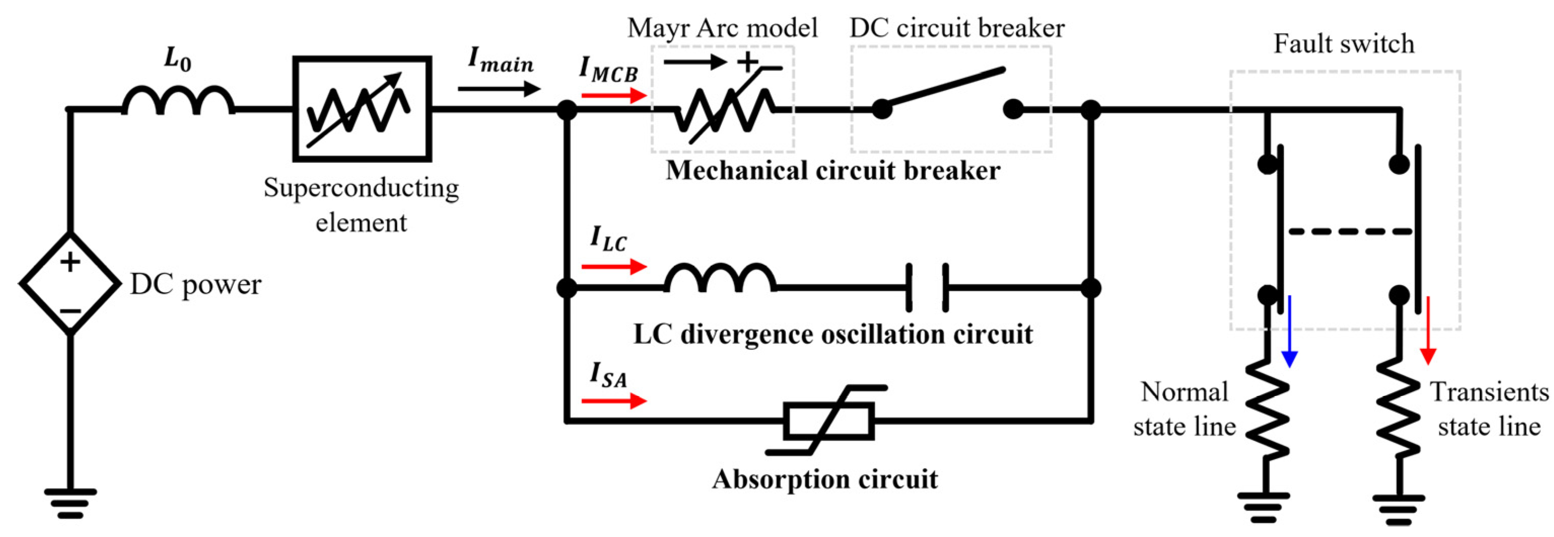
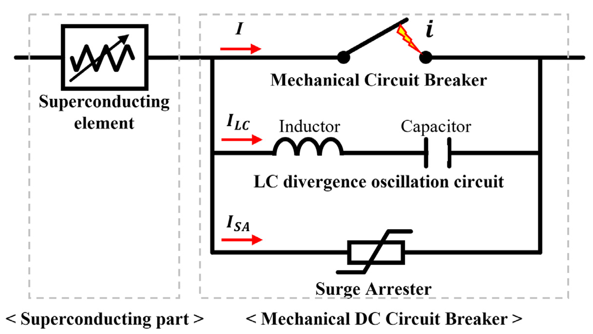
2.1. Principle and Mechanism of a Superconducting DC Circuit Breaker
2.2. LC Divergence Oscillation Circuit
3. Design of the Simulation
3.1. PSCAD/EMTDC Modeling
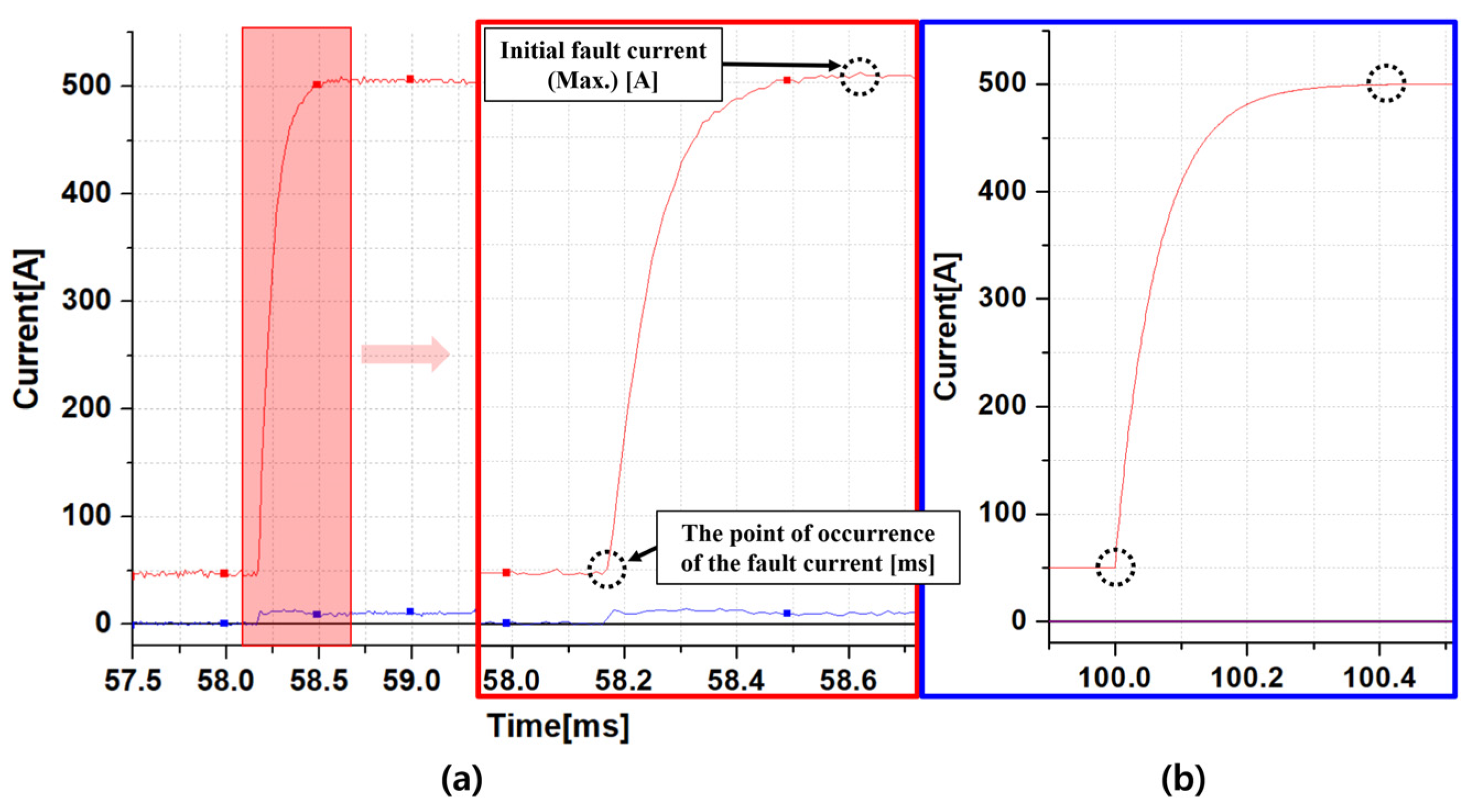
3.2. The Modeling of DC Initial Fault Current
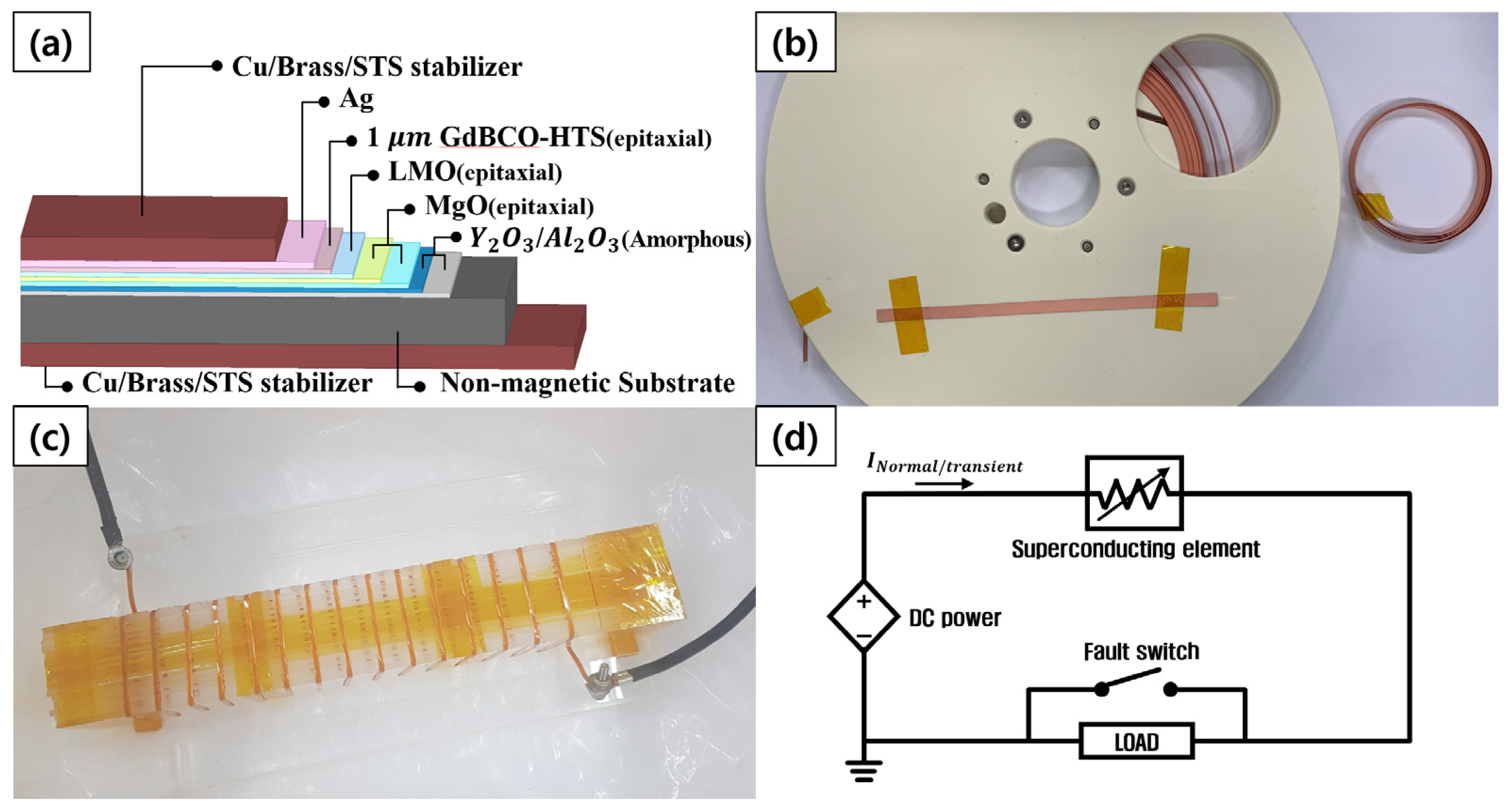
3.3. The Superconducting Element and Simulation Model
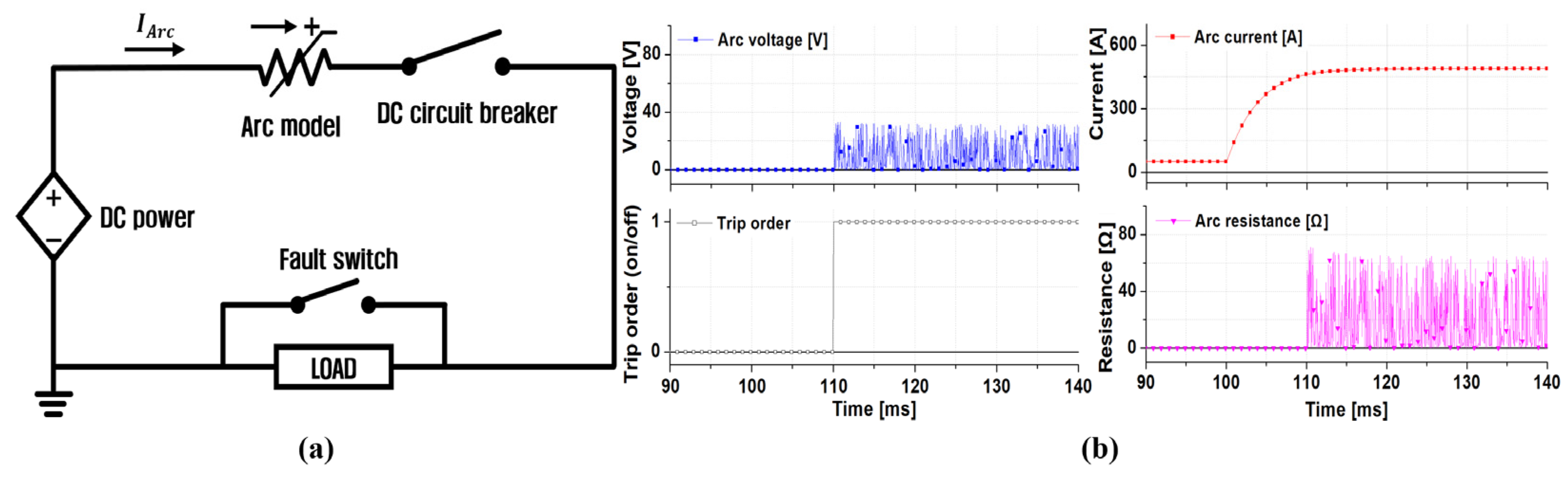
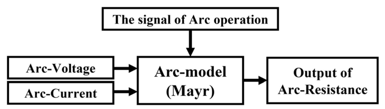
3.4. Arc Model
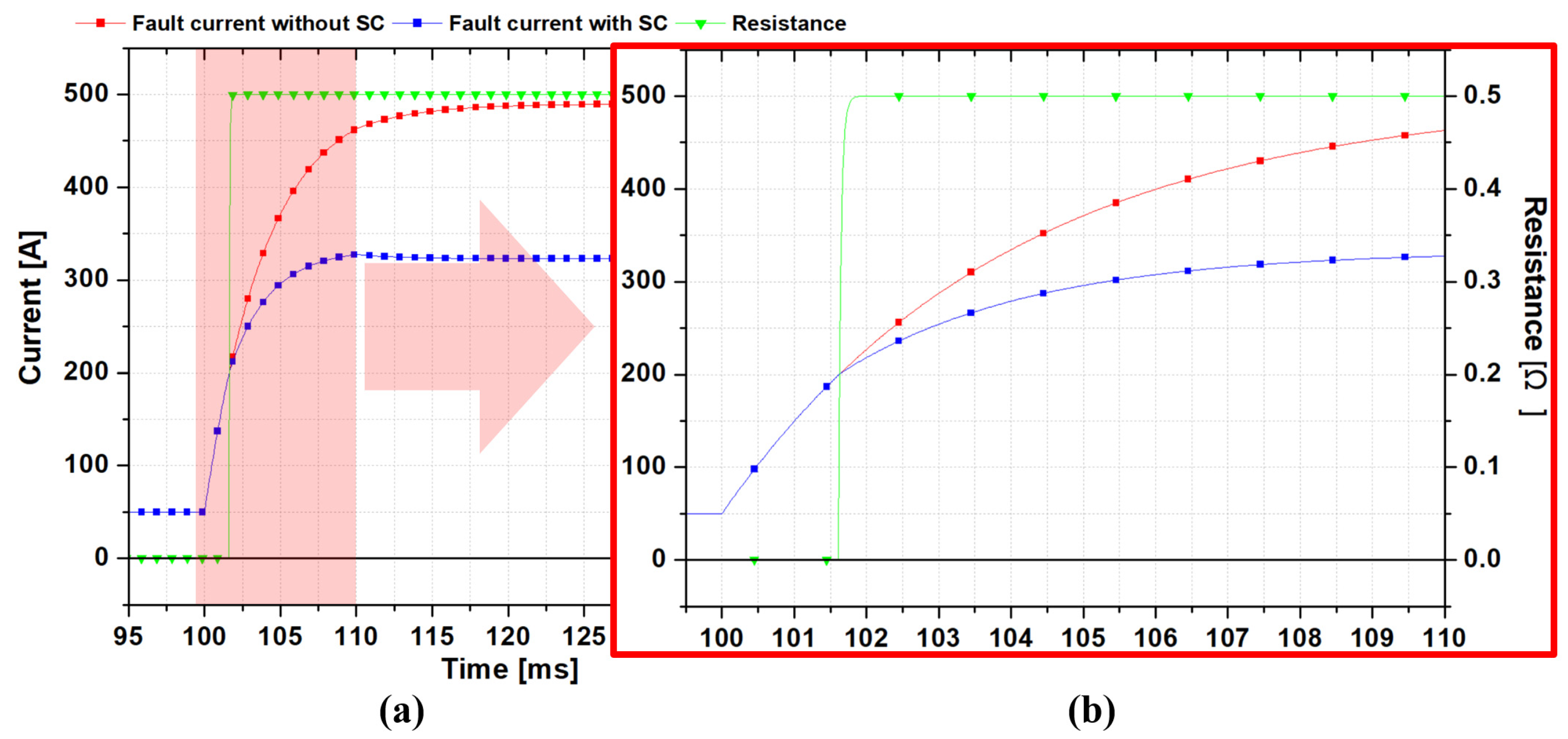
4. Results of the Simulation
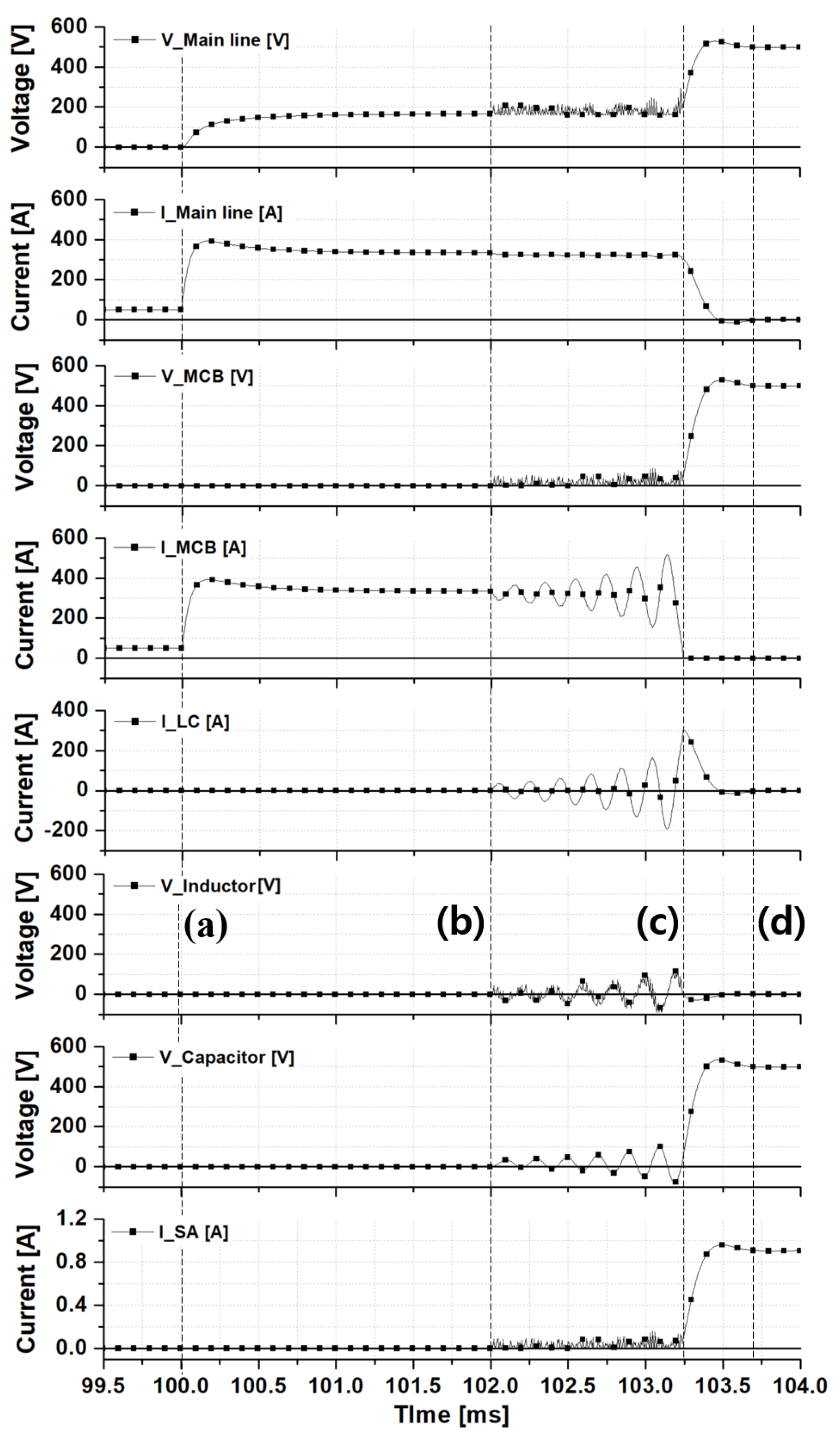
- (a)
- is the time point at which the simulated short-circuit fault occurred, which was approximately 100 .
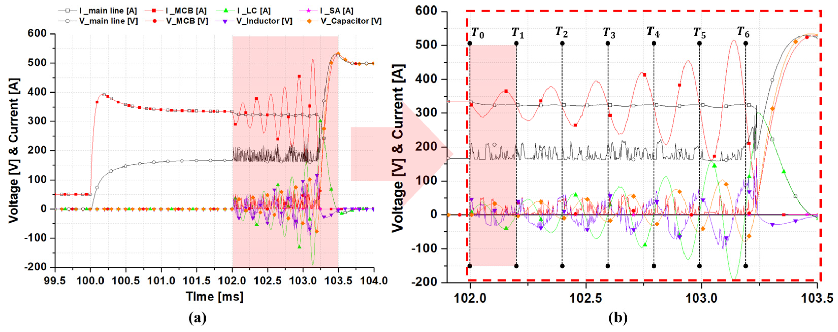
- (b)
- is the time point at which the MCB starts the opening operation, and it was about 102.0 .
- (c)
- is the time point at which the artificial current zero point of the fault current, which was approximately 103.2 .
- (d)
- is the time point when the fault current was completely cut off, and it was about 103.7 .
5. Review
6. Conclusions
Author Contributions
Funding
Institutional Review Board Statement
Informed Consent Statement
Data Availability Statement
Acknowledgments
Conflicts of Interest
References
- Sapkota, R.; Kolluri, S.; Adhikari, J.; Panda, S.K. MMC based multi-terminal HVDC subsea power transmission system with the integration of offshore renewable energy. In IEEE Innovative Smart Grid Technologies-Asia (ISGT-Asia); IEEE: Piscataway, NJ, USA, 2017; pp. 1–6. [Google Scholar] [CrossRef]
- Ahmed, N.; Norrga, S.; Nee, H.P.; Haider, A.; Hertem, D.; Zhang, L. HVDC SuperGrids with Modular Multilevel Converters—The Power Transmission Backbone of the Future. In Proceedings of the 9th International Multi-Conference on Systems, Signals and Devices, Chemnitz, Germany, 20–23 March 2012; pp. 1–7. [Google Scholar] [CrossRef]
- Le Metayer, P.; Paez, J.; Toure, S.; Buttay, C.; Dujic, D.; Lamard, E.; Dworakowski, P. Break-even distance for MVDC electricity networks according to power loss criteria. In Proceedings of the 23rd European Conference on Power Electronics and Applications (EPE’21 ECCE Europe), 6–10 September 2021; pp. 1–9. [Google Scholar]
- Hafez, O.; Bhattacharya, K. Optimal Break-Even Distance for Design of Microgrids. In IEEE Electrical Power and Energy Conference; IEEE: Piscataway, NJ, USA, 2012; pp. 139–144. [Google Scholar] [CrossRef]
- Parker, M.A.; Holliday, D.; Finney, S.J. DC protection for a multi-terminal HVDC network including offshore wind power, featuring a reduced DC circuit breaker count. J. Eng. 2019, 17, 4511–4515. [Google Scholar] [CrossRef]
- Mitra, B.; Chowdhury, B.; Manjrekar, M. HVDC transmission for access to off-shore renewable energy: A review of technology and fault detection techniques. IET Renew. Power Gener. 2018, 12, 1563–1571. [Google Scholar] [CrossRef]
- Ahmad, M.; Wang, Z. A Hybrid DC Circuit Breaker with Fault-Current-Limiting Capability for VSC-HVDC Transmission System. Energies 2019, 12, 2388. [Google Scholar] [CrossRef] [Green Version]
- Nadeem, M.H.; Zheng, X.; Tai, N.; Gul, M. Identification and Isolation of Faults in Multi-terminal High Voltage DC Networks with Hybrid Circuit Breakers. Energies 2018, 11, 1086. [Google Scholar] [CrossRef] [Green Version]
- Khalid, S.; Raza, A.; Alqasemi, U.; Sobahi, N.; Yousaf, M.Z.; Abbas, G.; Jamil, M. Technical Assessment of Hybrid HVDC Circuit Breaker Components under M-HVDC Faults. Energies 2021, 14, 8148. [Google Scholar] [CrossRef]
- Marroqui, D.; Blanes, J.M.; Garrugós, A.; Gutiérrez, R. Self-powered 380 V DC SiC solid-state circuit breaker and fault current limiter. IEEE Trans. Power Electron. 2019, 10, 9600–9608. [Google Scholar] [CrossRef]
- Li, H.; Yu, R.Z.; Yi, Z.; Yao, R.; Liao, X.L.; Chen, X.P. Design of 400 V miniature DC solid state circuit breaker with SiC MOSFET. Micromachines 2019, 5, 314. [Google Scholar] [CrossRef] [Green Version]
- Ludin, G.A.; Amin, M.A.; Matayoshi, H.; Rangarajan, S.S.; Hemeida, A.M.; Takahashi, H.; Senjyu, T. Solid-State DC Circuit Breakers and Their Comparison in Modular Multilevel Converter Based-HVDC Transmission System. Electronics 2021, 10, 1204. [Google Scholar] [CrossRef]
- Grenzheuser, J.; Lee, C.K. Power loss analysis of five-level inverters for grid tie photovoltaic system. In Proceedings of the 2013 5th International Conference on Power Electronics Systems and Applications (PESA), Hong Kong, China, 11–13 December 2013; IEEE: Piscataway, NJ, USA, 2013; Volume 12, pp. 1–6. [Google Scholar] [CrossRef]
- Grgić, I.; Vukadinović, D.; Bašić, M.; Bubalo, M. Calculation of Semiconductor Power Losses of a Three-Phase Quasi-Z-Source Inverter. Electronics 2020, 9, 1642. [Google Scholar] [CrossRef]
- Hafezi, H.; Faranda, R. A New Approach for Power Losses Evaluation of IGBT/Diode Module. Electronics 2021, 10, 280. [Google Scholar] [CrossRef]
- Liang, S.; Tang, Y.; Xia, Z.; Ren, L.; Chen, L.; Xu, Y.; Wang, Z.; Yan, S. Study on the Current Limiting Performance of a Novel SFCL in DC Systems. IEEE Trans. Appl. Supercond. 2017, 27, 1–6. [Google Scholar] [CrossRef]
- Li, B.; Wang, C.; Wei, Z.; Xin, Y.; Li, B.; He, J. Technical Requirements of the DC Superconducting Fault Current Limiter. IEEE Trans. Appl. Supercond. 2018, 28, 1–5. [Google Scholar] [CrossRef]
- Xiang, B.; Luo, J.; Gao, L.; Wang, J.; Geng, Y.; Liu, Z.; Ding, T. Protection schemes using resistive-type superconducting fault current limiters with mechanical DC circuit breakers in MMC-MTDC grids. IET Gener. Transm. Distrib. 2020, 14, 3422–3432. [Google Scholar] [CrossRef]
- Xiang, B.; Gao, L.; Luo, J.; Wang, C.; Nan, Z.; Liu, Z.; Geng, Y.; Wang, J.; Yanabu, S. A CO2/O2 Mixed Gas DC Circuit Breaker with Superconducting Fault Current-Limiting Technology. IEEE Trans. Power Deliv. 2020, 35, 1960–1967. [Google Scholar] [CrossRef]
- Xiang, B.; Cheng, N.; Yang, K.; Liu, Z.; Geng, Y.; Wang, J.; Yababu, S. SF6 passive resonance DC circuit breaker combined with a superconducting fault current limiter. IET Gener. Transm. Distrib. 2020, 14, 2869–2878. [Google Scholar] [CrossRef]
- Song, W.J.; Pei, X.O.; Xi, J.W.; Zeng, X.W. A novel helical superconducting fault current limiter for electric propulsion aircraft. IEEE Trans. Electrif. 2021, 3, 276–286. [Google Scholar] [CrossRef]
- Lee, H.Y.; Asif, M.; Park, K.H.; Mun, H.M.; Lee, B.W. Appropriate Protection Scheme for DC Grid Based on the Half Bridge Modular Multilevel Converter System. Energies 2019, 12, 1837. [Google Scholar] [CrossRef] [Green Version]
- Lee, J.I.; Dao, V.Q.; Dinh, M.C.; Lee, S.J.; Kim, C.S.; Park, M.W. Combined Operation Analysis of a Saturated Iron-Core Superconducting Fault Current Limiter and Circuit Breaker for an HVDC System Protection. Energies 2021, 14, 7993. [Google Scholar] [CrossRef]
- Park, S.Y.; Choi, H.S. Operation Characteristics of Mechanical DC Circuit Breaker Combined with LC Divergence Oscillation Circuit for High Reliability of LVDC System. Energies 2021, 14, 5097. [Google Scholar] [CrossRef]
- Park, S.Y.; Kim, S.H.; Choi, H.S. Analysis of Simulation Operation Characteristics of Superconducting DC Circuit Breaker According to L and C Elements of LC Divergent Vibration Circuit. In Proceedings of the IEEE International Conference on Applied Superconductivity and Electromagnetic Devices (ASEMD), Tianjin, China, 16–18 October 2020; pp. 1–2. [Google Scholar] [CrossRef]
- Park, S.Y.; Choi, H.S. Characteristics of a Superconducting DC Circuit Breaker According to L and C Elements of LC Divergent Oscillation Circuit. IEEE Trans. Appl. Supercond. 2021, 31, 1–4. [Google Scholar] [CrossRef]
- Xiang, B.; Junaid, M.; Gao, L.; Liu, Z.; Geng, Y.; Wang, J.; Yanabu, S. Effects of Short Circuit Currents on Quench and Recovery Properties of YBCO Tapes for DC SFCL. IEEE Trans. Appl. Supercond. 2019, 29, 1–6. [Google Scholar] [CrossRef]
- Zha, W.; Qiu, Q.; Cao, S.; Wang, H. Quench and Recovery Characteristics of Solenoid and Pancake SFCLs Under DC Impact Current. IEEE Trans. Appl. Supercond. 2020, 30, 1–6. [Google Scholar] [CrossRef]
- Matsushita, N.; Yanai, S.; Angkoolpakdeekul, T.; Shirai, Y.; Shiotsu, M. Recovery Characteristics of GdBCO Series-Connected Non-Inductive Coil in Pressurized Liquid Nitrogen for a Resistive SFCL. IEEE Trans. Appl. Supercond. 2020, 31, 1–5. [Google Scholar] [CrossRef]
- Mayr, O. Beiträge zur Theorie des statischen und des dynamischen Lichtbogens. Arch. Elektrotech. 1943, 37, 588–608. [Google Scholar] [CrossRef]
- Mayt, O. Über die Theorie des Lichtbogens und seiner Löschung. Elektrotech. Z. Jahrg. 1943, 64, 645–652. [Google Scholar]
- Schavemaker, P.H.; Van der Sluis, L. An Improved Mayr-Type Arc Model Based on Current-Zero Measurements. IEEE Trans. Power Deliv. 2000, 15, 580–584. [Google Scholar] [CrossRef]
- Mo, Y.; Bao, L.; Jia, S.; Shi, Z.; Qin, Y.; Cai, W. The Influence of Transient Interrupting Voltage on the Residual Plasma Dissipation in a 10 kV Mechanical DC Vacuum Circuit Breaker. In Proceedings of the 29th International Symposium on Discharges and Electrical Insulation in Vacuum (ISDEIV), Suzhou, China, 18–23 September 2021; pp. 286–289. [Google Scholar] [CrossRef]
- Jia, S.; Tang, Q.; Shi, Z. Review on HVDC circuit-breaker tests. In Proceedings of the 4th International Conference on HVDC, Xi’an, China, 6–9 November 2020; pp. 808–814. [Google Scholar] [CrossRef]
- Pauli, B.; Mauthe, G.; Ruoss, E.; Ecklin, G.; Poter, J.; Vithayathil, J. Development of a high current HVDC circuit breaker with fast fault clearing capability. IEEE Trans. Power Deliv. 1988, 3, 2072–2080. [Google Scholar] [CrossRef] [Green Version]
- Nakao, H.; Nakahoshi, Y.; Hatano, M.; Koshizuka, T.; Nishiwaki, S.; Kobayashi, A.; Murao, T.; Yanabu, S. DC Current Interruption in HVDC SF6 Gas MRTB by Means of Self-Excited Oscillation Superimposition. IEEE Trans. Power Deliv. 2001, 16, 62. [Google Scholar] [CrossRef]
- Shen, B.; Chen, Y.; Li, C.; Wang, S.; Chen, X. Superconducting fault current limiter (SFCL): Experiment and thesimulation fromfinite-element method (FEM) to power/energysystem software. Energy 2021, 234, 121251. [Google Scholar] [CrossRef]
- Zheng, F.; Deng, C.; Chen, L.; Li, S.; Liu, Y.; Liao, Y. Transient Performance Improvement of Microgrid by a Resistive Superconducting Fault Current Limiter. IEEE Trans. Appl. Supercond. 2015, 25, 6. [Google Scholar] [CrossRef]
- Parizad, A.; Baghaee, H.R.; Tavakoli, A.; Jamali, S. Optimization of Arc Model Parameters Using Genetic Algorithm. In Proceedings of the International Conference on Electric Power and Energy Conversion Systems (EPECS), Sharjah, United Arab Emirates, 10–12 November 2009; pp. 1–7. [Google Scholar]
- Van der Sluis, L.; Rutgers, W.R.; Koreman, C.G.A. A physical arc model for the simulation of current zero behavior of high-voltage circuit breakers. IEEE Trans. Power Deliv. 1992, 7, 1016–1022. [Google Scholar] [CrossRef]
- Panousis, E.; Bujotzek, M.; Christen, T. Arc cooling mechanisms in a model circuit breaker. IEEE Trans. Power Deliv. 2014, 29, 1806–1813. [Google Scholar] [CrossRef]
- CIGRE Working Group 13.01. Applications of Black Box Modelling to Circuit Breakers; Electra: Florence, Italy, 1993; pp. 41–71. [Google Scholar]


| Parameters | Value |
|---|---|
| Operating temperature | 77 K |
| 200 A | |
| Superconducting layer thickness | 0.11 mm |
| Superconducting layer width | 4.1 mm |
| Substrate | Stainless steel |
| Stabilizer | Copper |
| Coil pitch | 20 mm |
| Size | 80 × 80 × 400 mm |
| Total tape length | 5 m |
| Number of coil turns | 15 (Solenoid) |
[102.00] | [102.05] | [102.10] | [102.15] | [102.20] | |
|---|---|---|---|---|---|
| I_Mainline [A] | 333 | 325 | 324 | 324 | 324 |
| I_MCB [A] | 333 | 290 | 324 | 364 | 324 |
| I_LC [A] | 0 | 35 | 0 | −40 | 0 |
| I_SA [A] | 0 | 0 | 0 | 0 | 0 |
| V_Inductor [V] | 0 | −16 | −33 | −4 | 9 |
| V_Capacitor [V] | 0 | 16 | 33 | 13 | −5 |
[102.00] | [102.19] | [102.39] | [102.59] | [102.79] | [102.99] | [103.18] | |
|---|---|---|---|---|---|---|---|
| I_Mainline [A] | 333 | 324 | 324 | 323 | 324 | 324 | 324 |
| I_MCB [A] | 333 | 324 | 324 | 323 | 324 | 324 | 324 |
| I_LC [A] | 0 | 0 | 0 | 0 | 0 | 0 | 0 |
| I_SA [A] | 0 | 0 | 0 | 0 | 0 | 0 | 0 |
| V_Inductor [V] | 0 | 9 | 44 | 27 | 38 | 73 | 83 |
| V_Capacitor [V] | 0 | −5 | −11 | −20 | −32 | −51 | −80 |
Publisher’s Note: MDPI stays neutral with regard to jurisdictional claims in published maps and institutional affiliations. |
© 2022 by the authors. Licensee MDPI, Basel, Switzerland. This article is an open access article distributed under the terms and conditions of the Creative Commons Attribution (CC BY) license (https://creativecommons.org/licenses/by/4.0/).
Share and Cite
Park, S.-Y.; Kim, G.-W.; Jeong, J.-S.; Choi, H.-S. The Modeling of the LC Divergence Oscillation Circuit of a Superconducting DC Circuit Breaker Using PSCAD/EMTDC. Energies 2022, 15, 780. https://doi.org/10.3390/en15030780
Park S-Y, Kim G-W, Jeong J-S, Choi H-S. The Modeling of the LC Divergence Oscillation Circuit of a Superconducting DC Circuit Breaker Using PSCAD/EMTDC. Energies. 2022; 15(3):780. https://doi.org/10.3390/en15030780
Chicago/Turabian StylePark, Sang-Yong, Geon-Woong Kim, Ji-Sol Jeong, and Hyo-Sang Choi. 2022. "The Modeling of the LC Divergence Oscillation Circuit of a Superconducting DC Circuit Breaker Using PSCAD/EMTDC" Energies 15, no. 3: 780. https://doi.org/10.3390/en15030780
APA StylePark, S.-Y., Kim, G.-W., Jeong, J.-S., & Choi, H.-S. (2022). The Modeling of the LC Divergence Oscillation Circuit of a Superconducting DC Circuit Breaker Using PSCAD/EMTDC. Energies, 15(3), 780. https://doi.org/10.3390/en15030780