Article

Voltage-Sensorless Natural Frame Control for Single-Phase CHB Converter under Distorted Grid Conditions

1
Guangxi Key Laboratory of Power System Optimization and Energy Technology, Guangxi University, Nanning 530004, China
2
College of Electrical Engineering, Guangxi University, Nanning 530004, China
*
Author to whom correspondence should be addressed.
Energies 2022, 15(3), 769; https://doi.org/10.3390/en15030769
Submission received: 13 December 2021 / Revised: 15 January 2022 / Accepted: 17 January 2022 / Published: 21 January 2022
(This article belongs to the Section F3: Power Electronics)

Abstract

:
In this paper, a control scheme combining grid voltage sensorless control and natural frame control (NFC) has been proposed for single-phase cascaded H-bridge converter (CHB) under distorted grid conditions. Firstly, the virtual flux (VF) signal is estimated by a modified virtual flux estimator (VFE). Then the VF-based NFC is derived, using the estimated sinusoidal VF signal to generate the unit vectors for synchronization, which enables the omitting of the coordinate transformation, current quadrature signal generation, and phase-locked loop (PLL). Aiming at the problem that grid harmonic interference is not well considered in the conventional NFC and conventional voltage sensorless control, a current controller with enhanced harmonic-rejection ability is proposed in this paper. As a result, better steady-state performance and rapid transient response are achieved. The effectiveness of the proposed method has been verified on a prototype of the single-phase 3-cell CHB converter.

Graphical Abstract

1. Introduction

With the development of renewable energy resources, large amounts of distributed generation (DG), distributed energy storage systems, and local loads are connected to the utility grid [1]. Consequently, unideal conditions such as grid voltage unbalance and distortion are prone to occur at the point of common coupling (PCC) between the microgrids and the giant grid [2]. It has an undesirable influence on the control system of grid-connected converters in the DG (e.g., CHB in photovoltaic generation). Then the output current of the converters will be seriously distorted. Therefore, to improve the harmonic-rejection ability of the converter, the control strategy is required to eliminate the influence of grid voltage distortion on the output current.
On the one hand, the synchronization method used in the control strategy, which affects the input signal of the inner loop controller, should precisely and rapidly extract the fundamental sinusoidal signal or phase information for synchronizing under distorted grid conditions. The different filter schemes adopted by the synchronization method are roughly divided into the low-pass filter (LPF), notch filter, band-pass filter, comb filter, and others [3,4,5]. Cascaded delay signal cancellation (CDSC) has become a popular alternative due to its enhanced harmonic filtering performance, simple calculation, and better linear phase characteristics [6,7,8].
On the other hand, the impact of the distorted grid voltage on the output current should be eliminated by the control strategy. In [9,10,11], control schemes based on grid voltage feedforward were proposed. However, this method relies on the sampling of grid voltage. It will fail when the AC voltage sensor is faulty or missing. Yuan et al., proposed a multi-resonant controller (MRC) [12], which is basically the same as the methods proposed in [13,14]. These methods increase the harmonic peaks of the current loop by inserting several resonant controllers, thereby suppressing the background harmonics of grid voltage. However, the control structure of MRC is complicated. For the sake of simple structure and enhanced harmonics performance, repetitive controller (RC) [15,16,17] and modified RC [18] were proposed. But they were only verified in the synchronous rotating reference frame (dq frame) of three-phase converter.
The aforementioned current controllers can be realized in different reference frames, namely dq frame, stationary frame, and natural frame [19]. To simplify the structure of the control system, the natural frame control (NFC) is proposed in [20]. Compared with the conventional methods, the phase-locked loop (PLL) and the coordinate transformation are not needed in NFC. Consequently, the control structure of NFC is more compact, and the shortcomings of PLL-based methods, for example, complicated design of PLL parameters [21], and the limitation of the low-order current harmonic suppression ability [22], could be avoided. However, the potential distortion of grid voltage has not been considered in [20].
The above analysis has been carried out around the control system. As for the topology of the main circuit, unlike the ordinary two-level converters, the hardware cost of the CHB converter becomes a prominent issue. The grid voltage sensorless control has recently attracted much attention for reliability improvement and structure simplification [23]. The resolution limitations, mitigating noise, and other interferences caused by sensors can also be eliminated [24]. Moreover, the voltage sensorless method of converter can also be adopted as a complementary strategy when the sensors encounter faults [25]. The emphasis of grid voltage sensorless control relies on the accurate and fast estimation of fundamental grid voltage or VF, which can replace the grid voltage sensor [26]. However, the existing sensorless control methods have drawbacks, as follows. Firstly, the existing sensorless control methods are mainly based on ideal grid conditions without considering the distorted grid conditions [27,28,29]. The grid voltage is easily distorted because of the increase of nonlinear loads and distributed generators [30]. It brings new challenges to the synchronization link based on sensorless control. Secondly, in the grid voltage sensorless control, the grid voltage feedforward method cannot be implemented. The harmonic-rejection ability of the control system will be weakened, which results in the inability to adapt to the distorted grid conditions. Thirdly, the majority of the existing sensorless control methods are conducted in three-phase system. The 2nd-order ripple voltage of DC-link of single-phase converter will deteriorate the output voltage and current of the converter [31], which has higher requirements for the harmonics rejection ability of control system.
Regarding the problems mentioned above, in this paper, the grid voltage sensorless control for the single-phase grid-connected converter under distorted grid conditions has been studied. Then a novel control scheme that combines voltage sensorless control and NFC is proposed for a single-phase CHB converter. Firstly, the fundamental sinusoidal VF is estimated by the VFE based on three cascaded first-order low-pass filters and CDSC, then the calculation formula of AC current reference based on VF is deduced. Secondly, a controller has been proposed, which integrates the proportional-resonant (PR) controller and RC in natural frame to realize the tracking of fundamental current reference signal and rejection of grid harmonics interference. Finally, the DC-links voltage balance of CHB is guaranteed with the balancing strategy.
Experimental results verify that the proposed methods have the merits of a fast and smooth dynamics process consistent with NFC and excellent anti-harmonic interference ability. In the case of a similar power rate of converter, when compared with other methods, lower total harmonic distortion (THD) of grid current is achieved with the proposed sensorless control method, even under more severe grid voltage distortion.
The rest of this article is organized as follows. Theoretical analysis of the single-phase CHB converter is introduced in Section 2. Next, the principle of VF estimation is detailed in Section 3. In Section 4, the NFC based on VF is deduced, and the analysis and design of current controller under distorted grid conditions are presented. Then, the experimental verification is given in Section 5. Finally, Section 6 concludes this paper.

2. Theoretical Analysis under Distorted Grid Voltage

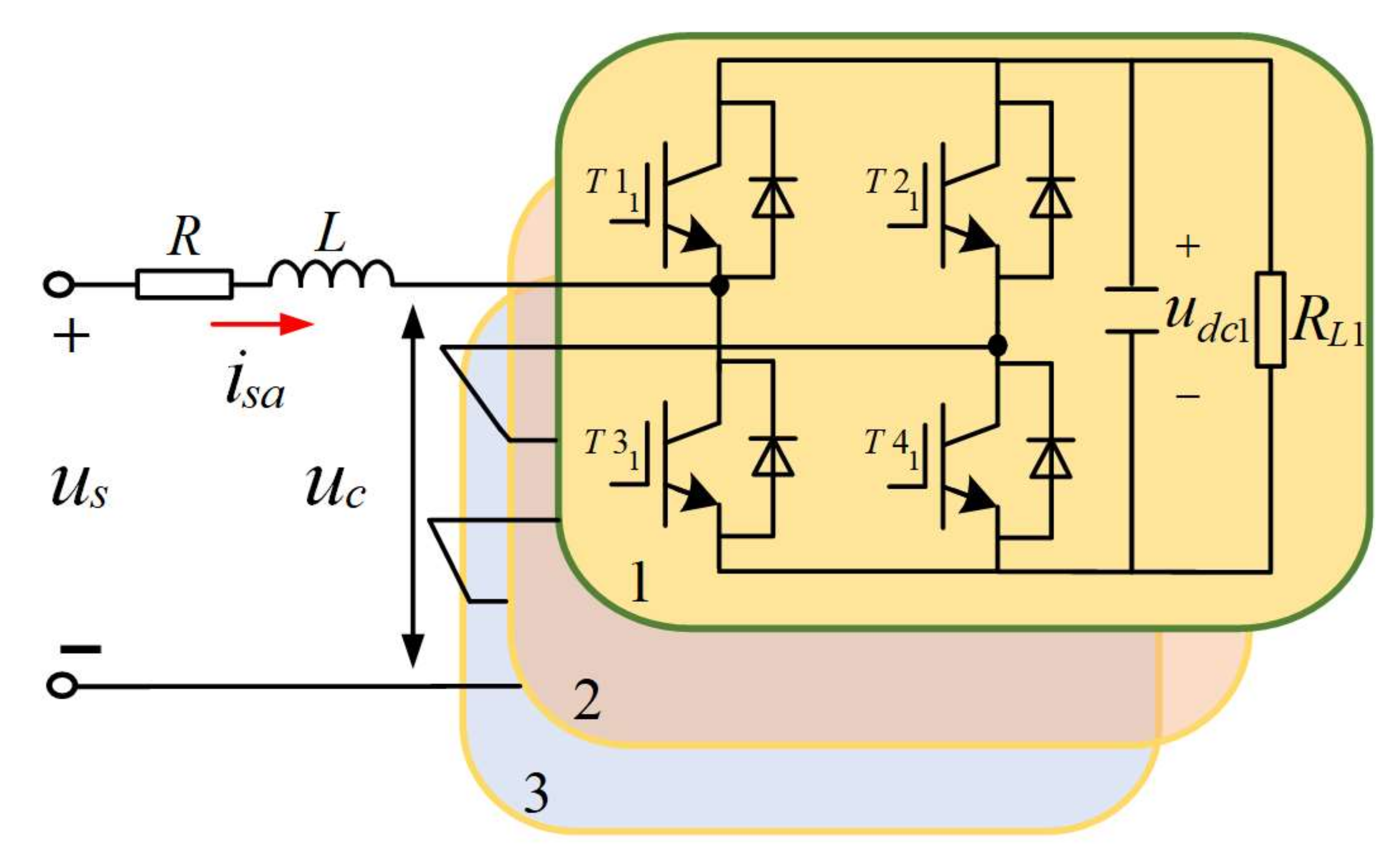
2.1. Mathematical Model of Single-Phase 3-Cell CHB Converter

Figure 1 shows the topology of single-phase 3-cell CHB converter, with 3 H-bridges connected in cascade on AC side.
The voltage equation of the single-phase CHB converter is expressed as:
u s - R i sa - L d i s a d t - u c = 0
and uc is the AC side voltage of CHB converter:
u c = i = 1 3 u c i = i = 1 3 S W i u d c i
where L, R are filter’s inductor and its equivalent resistor, respectively. us is the grid voltage, isa is the input current of CHB converter. The SWi and udci are switching functions and DC-side voltages of H-bridge cells, respectively, and the RLi are load resistances parallel to the capacitors in the DC-side of each cell (i = 1,2,3).

2.2. Extraction of Fundamental Sinusoidal Signal under Distorted Grid Conditions

In practice, various disturbances, such as harmonics and frequency variation, may occur in the grid voltage, deteriorating the steady-state accuracy and transient dynamics of the grid synchronization link and the control system. To extract a more sinusoidal VF signal used for generating unit vectors of NFC under distorted grid conditions, a CDSC proposed in [7] is used in this paper. By embedding CDSC into the VFE, harmonic components can be effectively eliminated.

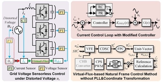
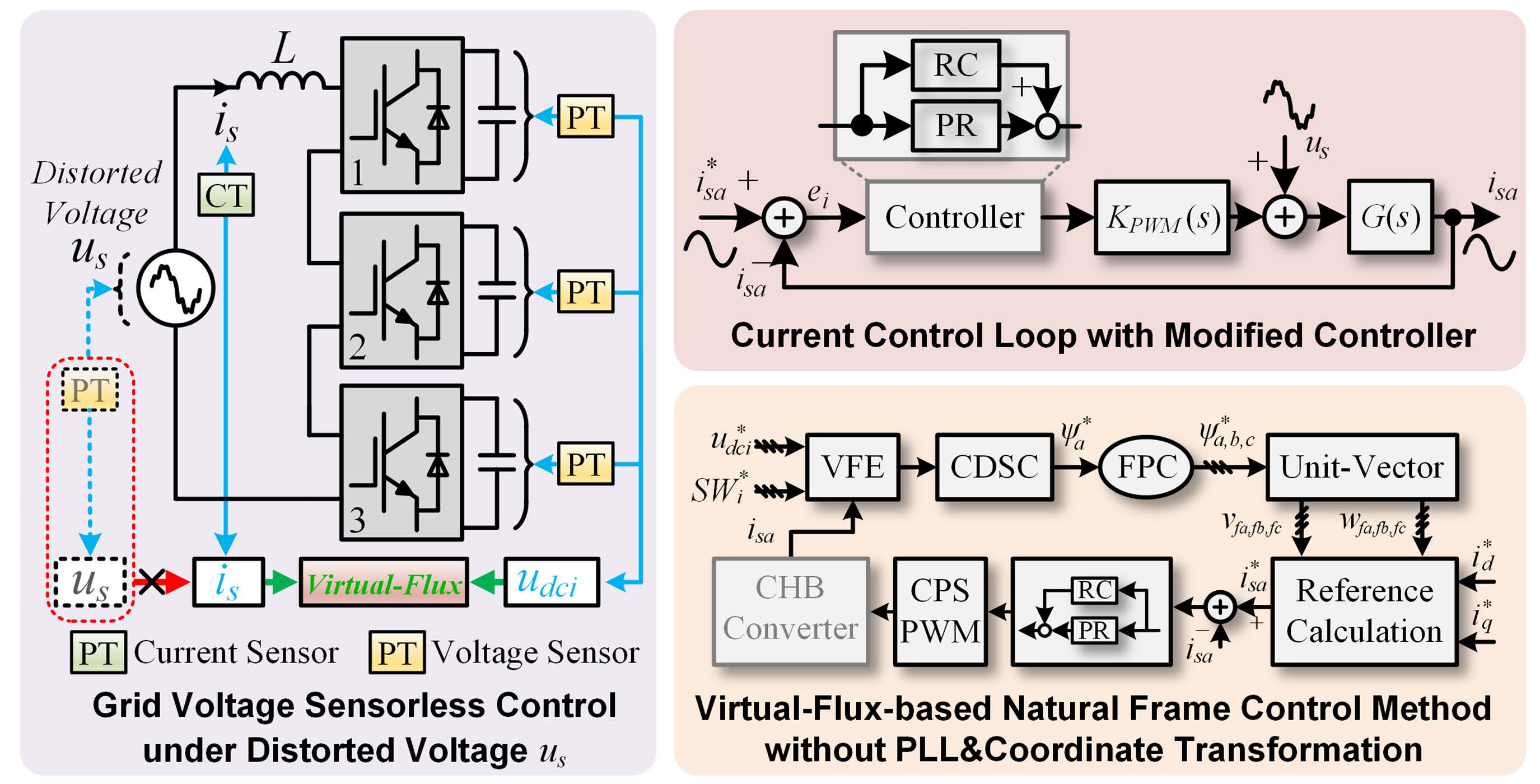
3. Grid Voltages Sensorless Method Based on Virtual Flux Estimation

The control system is configured as a double closed-loop control structure composed of the outer voltage loop (including DC cluster voltage control and voltage balancing control) and the inner current loop. The entire control diagram of the proposed NFC based on AC voltage sensorless control is presented in Figure 2.
According to the control objectives of the single-phase CHB converter, the first part is designed to track the AC side current. First, udc1, udc2, udc3, and isa are sampled and input into the grid-side voltage construction, VFE and CDSC to obtain the filtered VF (ψ*a), and then the fictive phase construction (FPC) [20] method is used to construct a three-phase VF signal (ψ*a, ψ*b, ψ*c). The reactive flux unit vector (RFUV) and active flux unit vector (AFUV) are then calculated in (13) and (14), respectively. Then, in the DC cluster voltage controller, the error of the measured DC-side voltage ∑udci and DC voltage reference u*ref =∑ u d c i * are input into the PI controller to output an active current reference signal i*d. The reactive current reference i*q can be regulated for different power factors and operating conditions. When the i*q is changed, the power factor of the converter will also change. For example, when the i*q is set to zero, the CHB converter will operate in the unit power factor mode. Furthermore, AC reference current i*sa is calculated by (16).
The second part is to achieve the balance control of the DC voltage. Therefore, the DC voltage balancing controller is adopted. By subtracting udc1, udc2, udc3 from DC-link reference voltages u*ref /3, respectively, the errors are input to PI regulators to obtain d-axis compensation Δp1, Δp2, and Δp3 in the DC-link voltage balancing controller. The d-axis compensation components are then multiplied by the AFUV vector vfa to obtain each H-bridge voltage compensation components (up1, up2, up3). Therefore, the controller generates modulated voltage signals u*sa1, u*sa2, u*sa3, which are finally modulated by carrier phase shift PWM (CPS-PWM).

3.1. Principles of VF Estimation

Because the equivalent resistance of the inductor is so small that to be omitted, (1) is simplified as:
u s = L d i s a d t + u c
Integrating (3), the grid flux ψs can be obtained as:
ψ s = u s d t = L i s a + u c d t = L i s a + ψ c
where ψc is defined as the flux of the CHB converter.

3.2. VFE Based on Three Cascaded First-Order Low-Pass Filters

The VFE based on three cascaded first-order LPFs was proposed in [32], and the transfer function is given as:
G T L P F ( s ) = x x ( s ) = K s + ω c 3
where x is the input signal, x′ is the output signal. To obtain the virtual flux, the parameters of GTLPF(s) should satisfy the following criteria:
K 3 ω 0 2 + ω l 2 3 / 2 = 1 ω 0 3 arctan ( ω 0 / ω l ) = 4 π
According to (6), the parameters can be selected as follows:
K = 2 ω 0 2 / 3 ω l = 3 ω 0
where ω0 = 100π is the angular frequency of fundamental signal. So the amplitude and phase change of the output fundamental signal of VFE is equal to the theoretical ones of pure integrator.
It is worth noticing that the VFE mentioned above is designed without considering the grid distortion. So that the estimated virtual flux will distort under the unideal grid voltage. To enhance the compatibility of the sensorless control method under the unideal grid condition, the VFE should be modified by cascading an extra filter to reject the harmonic interference in the grid better.

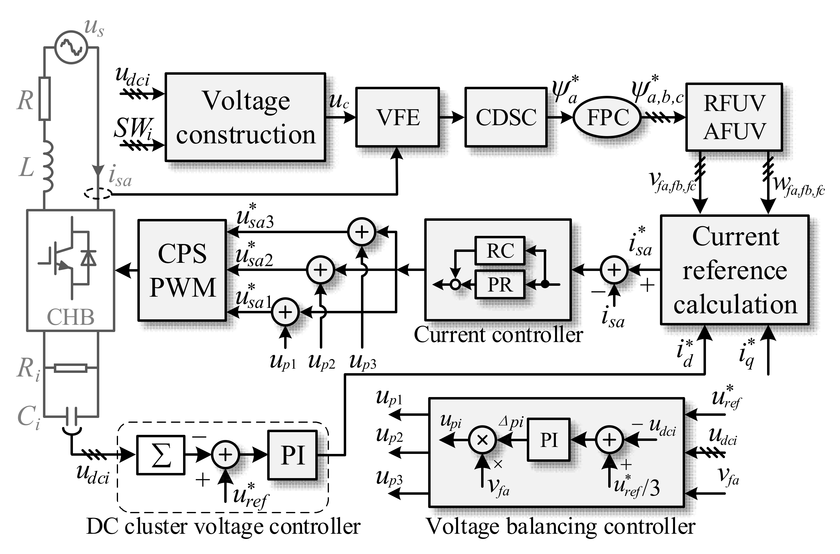
4. Natural Frame Control Based on Virtual Flux

4.1. Principles of VF-Based NFC

Assuming that the grid voltages in a three-phase system are sinusoidal and balanced, the voltage-oriented vector control is used. According to the instantaneous power theory, different control strategies carried out in natural frame can achieve the same control goals as in dq frame. Therefore, decoupled control of active and reactive currents and be realized by using 2r/3s coordinate transformation to generate the instantaneous current references in natural frame, as follows:
i s a * i s b * i s c * = cos ( ω 0 t ) cos ( ω 0 t 2 π / 3 ) cos ( ω 0 t + 2 π / 3 ) sin ( ω 0 t ) sin ( ω 0 t 2 π / 3 ) sin ( ω 0 t + 2 π / 3 ) i d * i q *
where (i*sa, i*sb, i*sc) and (i*d, i*q) are the current references in the natural frame and the dq frame, respectively.
The amplitude of active and reactive voltage vector can be expressed as:
E s = 2 3 ( e a 2 + e b 2 + e c 2 ) E s Λ = 2 3 ( e a Λ 2 + e b Λ 2 + e c Λ 2 )
where es = (ea, eb, ec)T and e^s = (e^a, e^b, e^c) are defined as the active vector and the reactive vector of grid-side instantaneous voltages, and
E s = E s Λ = U m
In detail, the AVUV and the RVUV in NFC [20] are defined as:
v a = e a / E s = cos ( ω 0 t ) v b = e b / E s = cos ( ω 0 t 2 π / 3 ) v c = e c / E s = cos ( ω 0 t + 2 π / 3 )
and
w a = e a Λ / E s Λ = sin ( ω 0 t ) = ( v c v b ) / 3 w b = e b Λ / E s Λ = sin ( ω 0 t 2 π / 3 ) = ( v a v c ) / 3 w c = e c Λ / E s Λ = sin ( ω 0 t + 2 π / 3 ) = ( v b v a ) / 3
Considering the phase and amplitude relationship between the grid voltage and grid VF:
e s = d ψ s d t = ω 0 ψ s e s Λ = d ψ s d t = ω 0 ψ s
where ψs = (ψa, ψb, ψc)T, and ψs is the quadrature delayed value of the estimated VF. Therefore, the AFUV and RFUV are calculated using the estimated VF as:
w f a = ψ a / ψ s w f b = ψ b / ψ s w f c = ψ c / ψ s
and
v f a = ( w f b w f c ) / 3 v f b = ( w f c w f a ) / 3 v f c = ( w f a w f c ) / 3
where
ψ s = 2 3 ( ψ a 2 + ψ b 2 + ψ c 2 )
Combining (8) and (11)–(15), the instantaneous reference currents based on VF in the natural frame system are obtained as:
i s a * = i d * v f a + i q * w f a i s b * = i d * v f b + i q * w f b i s c * = i d * v f c + i q * w f c
In this paper, the control strategy is conducted on the single-phase CHB converter. Only i*sa is calculated as the reference current of the inner loop, while the other current references are not needed.

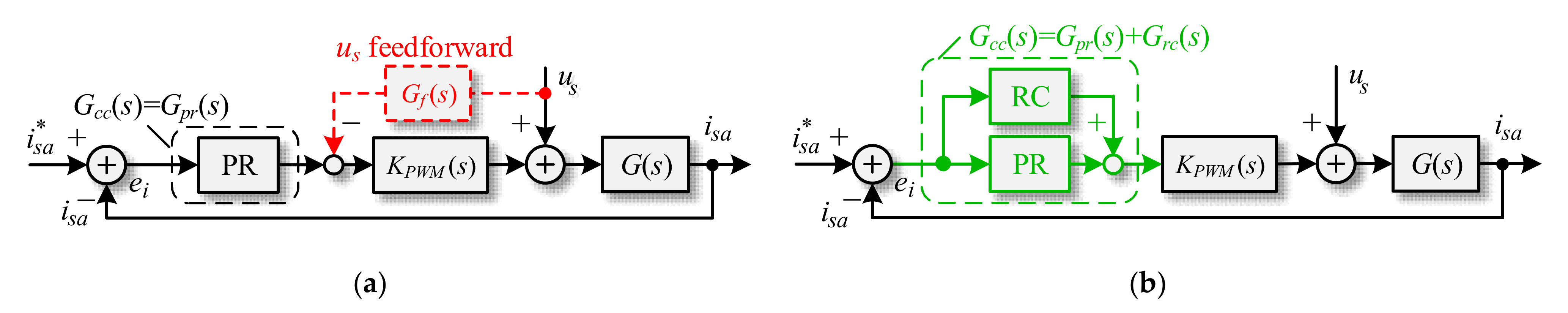
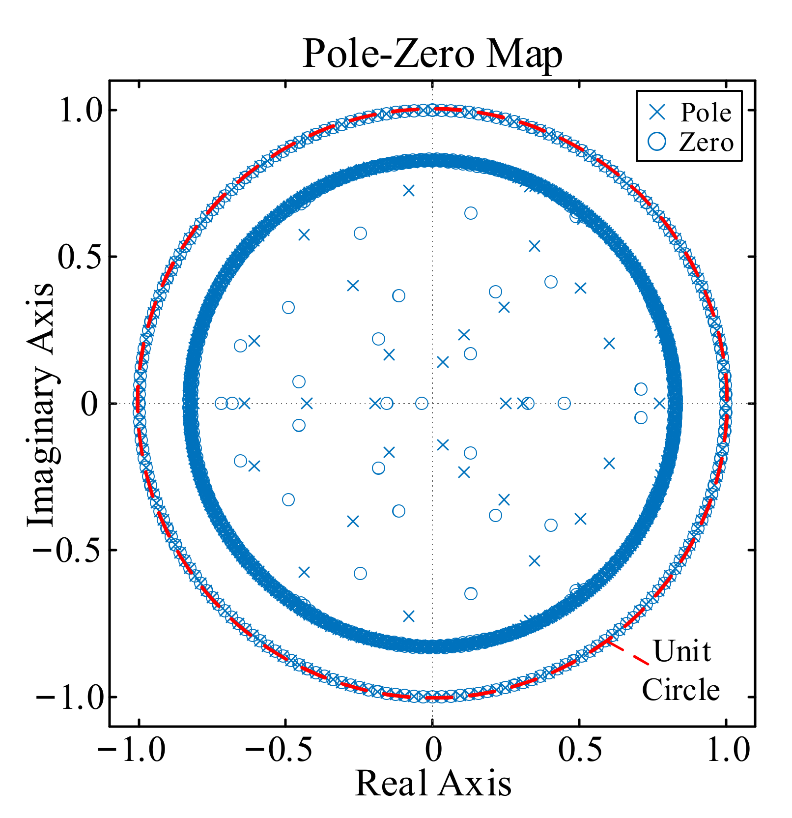
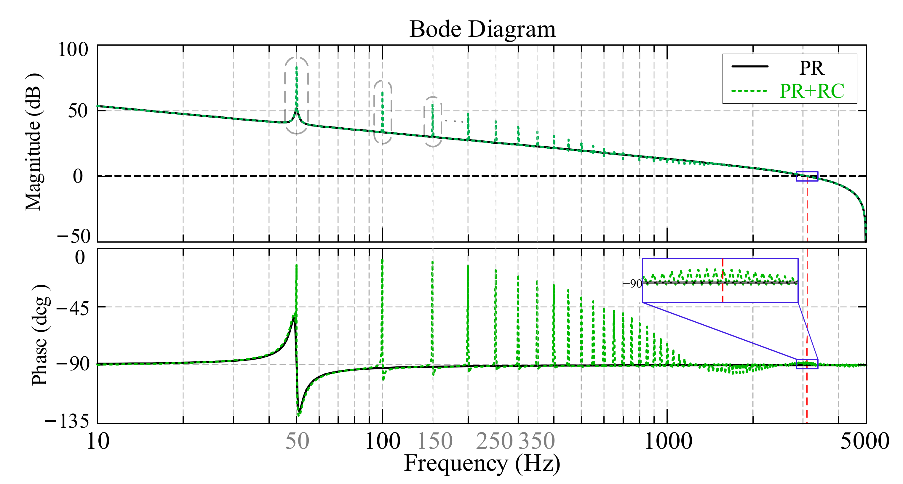
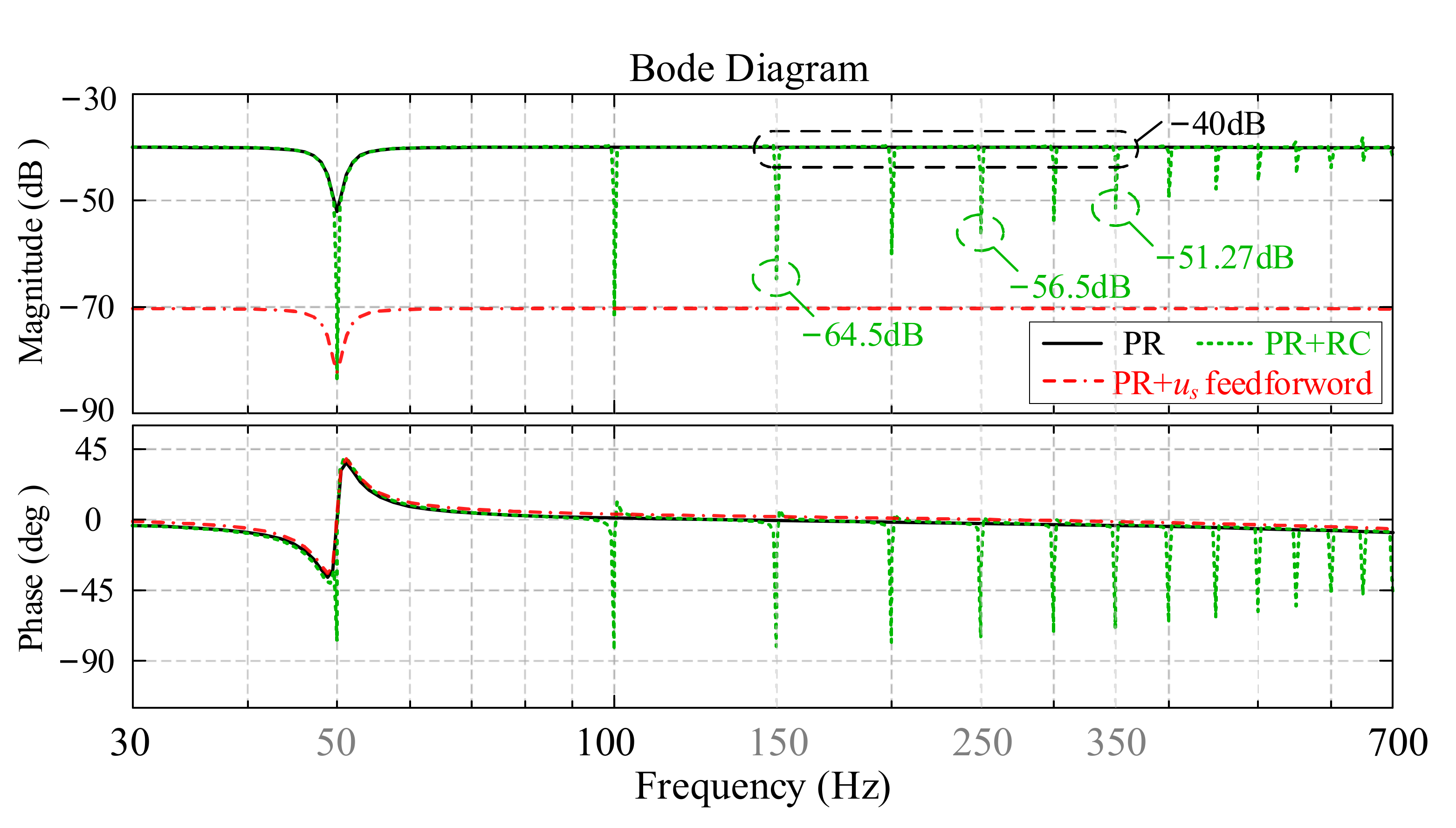
4.2. Analysis and Design of Current Controller under Distorted Grid Conditions

On the traditional control method with grid voltage sensor, shown in Figure 3a, the grid voltage feedforward method can be used to enhance the harmonics rejection ability of control link. However, under the grid voltage sensorless control method, without the precise sampling of grid voltage, the voltage feedforward method cannot be implemented. Consequently, it is necessary to enhance the system’s ability of harmonics suppressing in the grid voltage sensorless control.
Figure 3 shows the block diagram of the current control loop. From (1), it can be seen that the transfer function of the converter is G(s) = isa/uc = 1/(sL + R), and the transfer function of the modulation link of the converter can be simplified as KPWM = 1. Based on Figure 3, the expression of the output current is:
i s a ( s ) = G i r i ( s ) i s a * ( s ) + G i g v ( s ) u s ( s )
where Gi-ri(s) is the transfer function from the reference current to grid current, and Gi-gv(s) is the transfer function from grid voltage to grid current:
G i r i ( s ) = i s a ( s ) i s a * ( s ) = G c c ( s ) G ( s ) 1 + G c c ( s ) G ( s )
G i g v ( s ) = i s a ( s ) u s ( s ) = G ( s ) 1 + G c c ( s ) G ( s ) 1 Z o u t
In (20), Zout depicts the characteristic of output impedance of the converter, which reflects the impacts of grid voltage on the output current, and Gcc(s) is the transfer function of current controller. When the filter is selected, the transfer function G(s) = 1/(sL + R) is constant. In traditional NFC, PR controller is selected as Figure 3a, so that Gcc(s) = Gpr(s). As depicted in (20), the higher gains of Gcc(s) at specific harmonics are, the greater the harmonic impedance will be, which enables a better attenuation effect on the harmonics. In order to increase the harmonic impedance of current loop, the current controller combines PR and RC is proposed in this paper. Figure 3b shows the block diagram of the above-mentioned PR + RC current control loop, the transfer function Gcc(s) = Gpr(s) + Grc(s) is presented as:
G c c ( s ) = K p + K r 2 ω i s s + 2 ω i s + ω 0 2 G p r ( s ) + K r c e T 0 s G l p ( s ) 1 e T 0 s G l p ( s ) G l d ( s ) G r c ( s )
where Gpr(s), Grc(s) are the transfer function of PR controller and RC, respectively. After the PR controller is tuned, the RC can be designed in the discrete domain, the digital form of Grc(s) is expressed as:
G r c ( z ) = K r c z N G l p ( z ) 1 z N G l p ( z ) G l d ( z )
where Glp(z), Gld(z) are the low-pass filter and the phase-lead compensator, can be defined as:
G l p ( z ) = α ( z + z 1 ) + β ( α > 0 , β > 0 , 2 α + β = 1 )
G l d ( z ) = z m
According to [17], if all the roots of Ge-ri(z) (the discrete transfer function from reference current i s a * to current error ei) locate inside the unity circle, the entire current control loop will be stable. The transfer function Ge-ir(z) can be described as:
G e r i ( z ) = e i ( z ) i s a * ( z ) = 1 G c l p r ( z ) 1 + z 1 G r c ( z ) G ( z ) [ 1 G c l p r ( z ) ]
the Gclpr(z) is the close loop transfer function of PR controller in z-domain:
G c l p r ( z ) = z 1 G p r ( z ) G ( z ) 1 + z 1 G p r ( z ) G ( z )
with the equivalent resistance of filter is ignored, the transfer function G(s) can be discretized as:
G ( z ) = 1 s L s = 1 z 1 1 + z 1 2 T s = 1 + z 1 1 z 1 T s 2 L
Substituting (22) into (25):
G e r i ( z ) = 1 z N G l p ( z ) G c l p r ( z ) + z N G l p ( z ) G c l p r ( z ) 1 z N [ G l p ( z ) K r c z 1 G l p ( z ) G ( z ) G l d ( z ) ( 1 G c l p r ( z ) ) ]
then the stability criterion of RC designing can be expressed as:
G l p ( z ) K r c z 1 G l p ( z ) G ( z ) G l d ( z ) ( 1 G c l p r ( z ) ) 1
where z = ejωt (0 < ω < π/Ts). According to (23) and (29), parameters of RC are selected as: Krc = 1.8, α = 0.125, β = 0.75, m = 4 and N = fs/f = 256.
Figure 4 shows the zero-pole map of the control system. With the properly tuning of controllers, all the poles of this control system lie inside the unit circle so that stability is guaranteed.
Figure 5 shows the Bode diagram of the open-loop transfer function of the traditional PR controller and the proposed controller. Apparently, due to the embedding of RC in the proposed method, the open-loop amplitude gains at both fundamental frequency and specific harmonics frequency are significantly increased. The phase margins of the conventional and proposed methods are 90°and 89.6°respectively, and the gain margins are both infinite.
For further comparison, the Bode diagram of Gi-vg(s) is shown in Figure 6. It is worth noting that the grid voltage (us) feedforward method can effectively improve the harmonics-rejection capability of the control system, but the grid voltage sensor is needed. When the voltage sensorless control method is implemented, compared with the traditional PR controller, the proposed method can significantly increase the harmonic impedance at integer frequencies ranging from 2nd- to 13th-order. For example, the amplitude of harmonic impedances are increased from 100 (−40 dB) to 1678.8 (−64.5 dB), 668.3 (−56.5 dB), and 366 (−51.27 dB), respectively. It results in a better rejection ability against background harmonics.

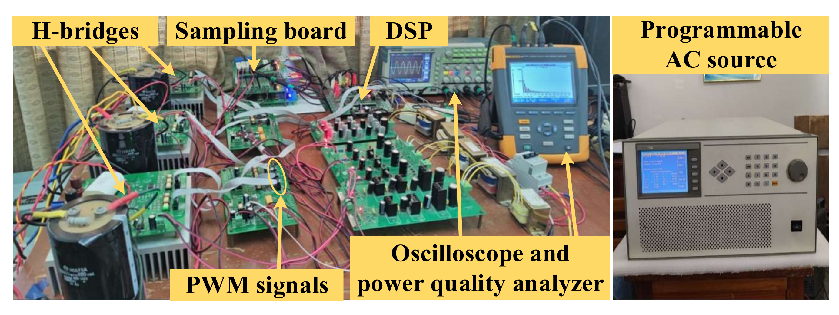
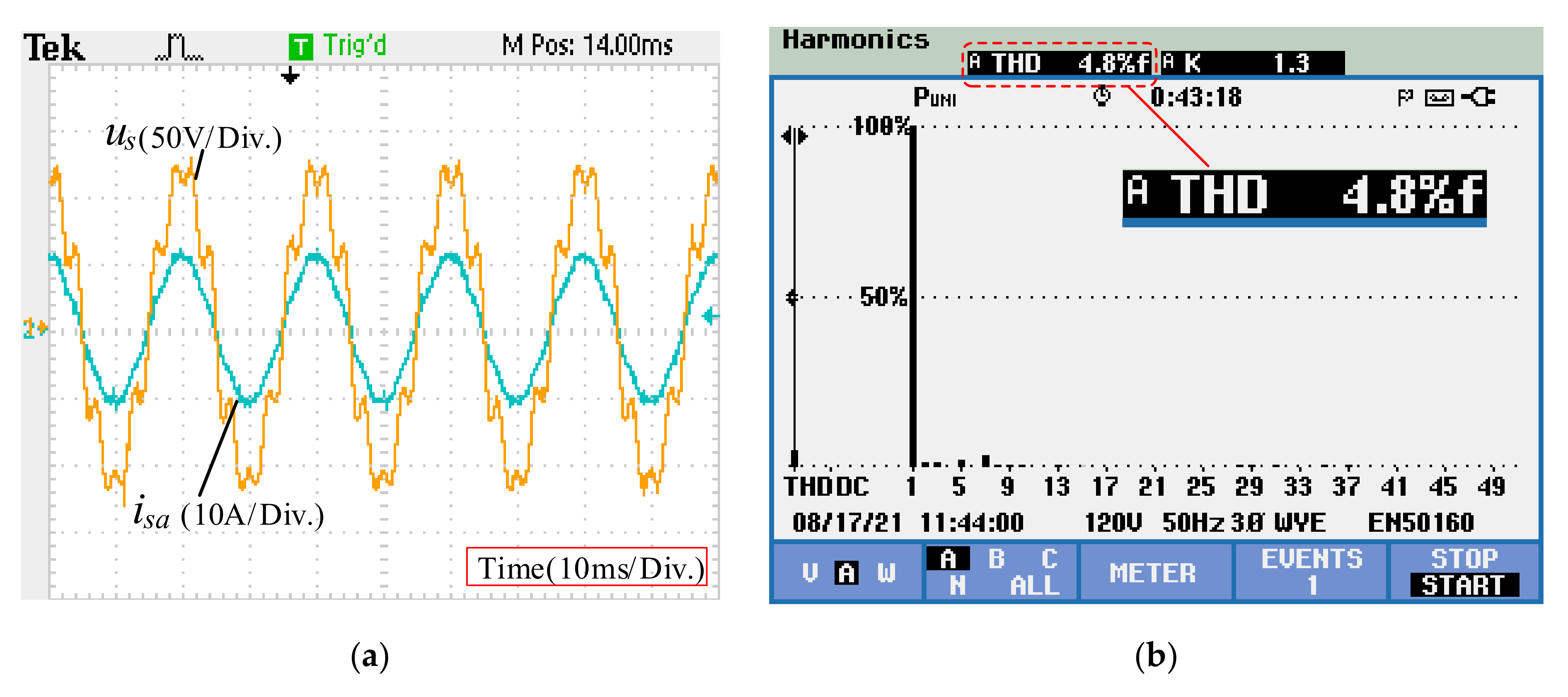
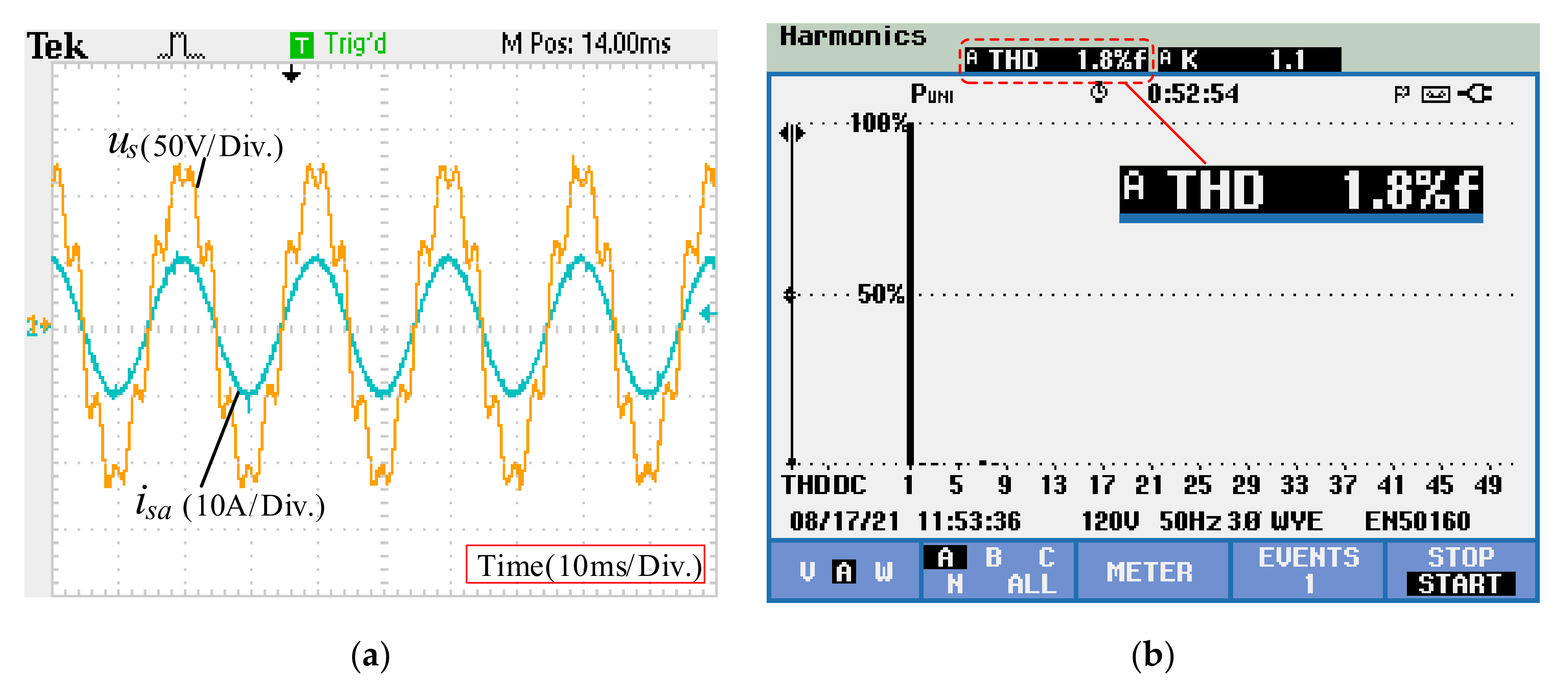
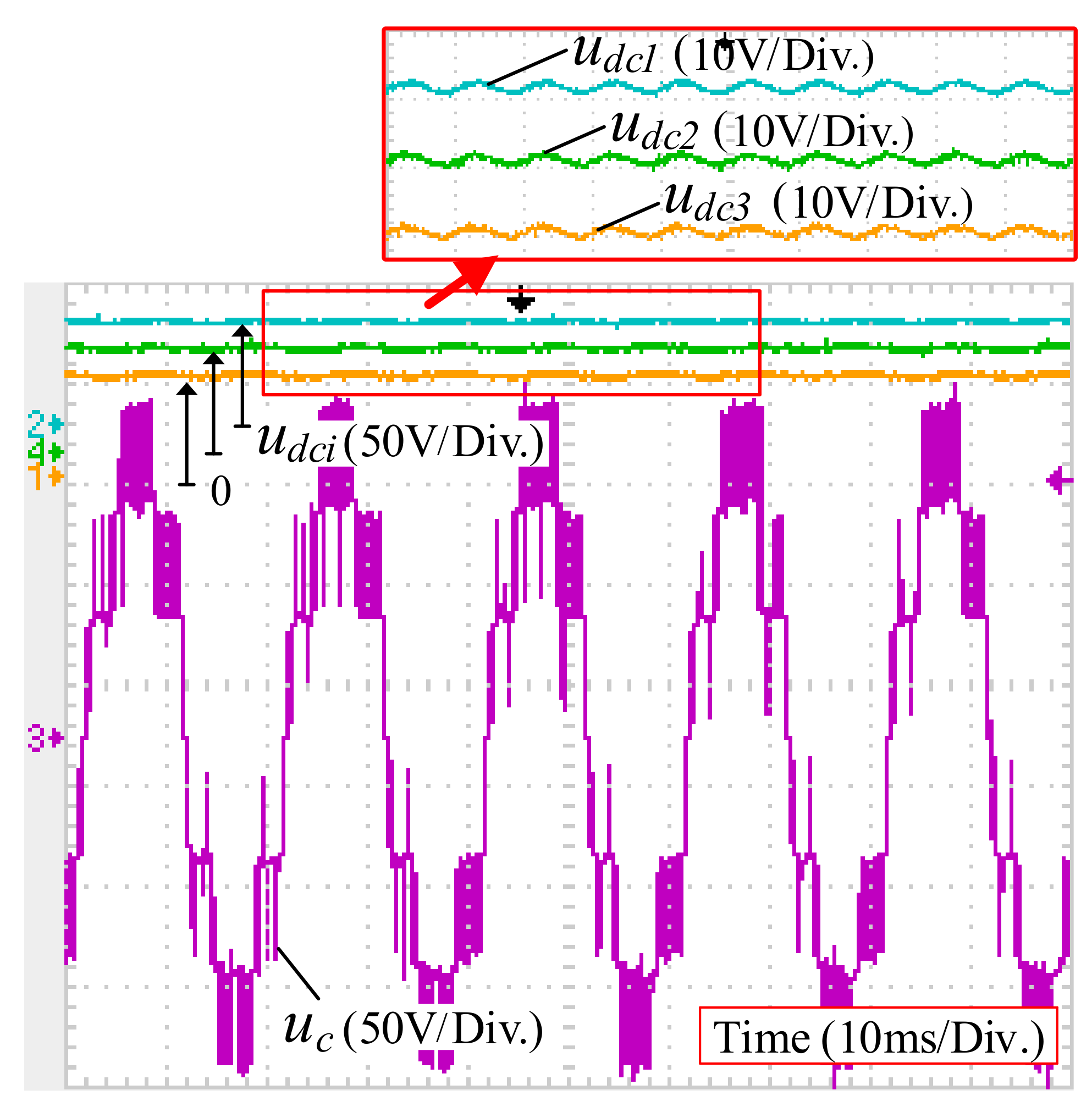
5. Experiment Research

For the verification of the proposed method, a couple of experimental tests are conducted on a single-phase 3-cell CHB converter. The experimental setup is shown in Figure 7, system and control parameters are provided in Table 1. The proposed control method is implemented by a DSP (TI TMS320F28377D). A single-phase programmable AC source (Chroma 6530) has been used to produce the sinusoidal and distorted voltages. The oscilloscope (Tektronix 2024) and power quality analyzer (Fluke 435-II) are used to observe and analyze the experimental waveforms.
Figure 8 illustrates the steady-state experimental waveforms of grid voltage and the estimated VF with the proposed method under sinusoidal and distorted grid conditions. In Figure 8a, the grid voltage is sinusoidal, while in Figure 8b, the grid voltage is distorted with harmonic components of 2.3% 2nd-order, 9.8% 5th-order, 15.8% 7th-order, and 2.5% 8th-order. It is shown that the VFE accurately estimates the sinusoidal VF signal under both sinusoidal and distorted grid voltage, which can be used as the synchronization signal of sensorless control. Consequently, the AFUV and RFUV can be derived correctly, and the sinusoidal current reference can be calculated. Therefore, the proposed VFE has satisfied steady-state performance.
Figure 9 shows the steady-state results comparison of conventional NFC and the proposed voltage sensorless control method under sinusoidal and distorted grid conditions. From Figure 9, we can conclude that both the conventional NFC and the proposed method perform well under sinusoidal grid conditions. However, as shown in Figure 9c,d, the proposed method is robust to the severe harmonic disturbance so that the sinusoidal and in-phase grid current with THD of 1.8% is obtained. In comparison, the conventional NFC is vulnerable to background harmonics with THD of 14.5%. In addition, unit power factor operation is achieved with the proposed method, which shows that the decoupling control of active and reactive power is effectively realized.
Figure 10 shows the steady-state results of traditional voltage sensorless control method [33]. Figure 11 shows the proposed voltage sensorless control. Consistent with the theoretical analysis, the proposed method can effectively adapt to the distorted grid conditions and get sinusoidal current. Besides, compared with the traditional voltage sensorless control, the current with the proposed method has lower harmonic content.
Figure 12 shows the dynamic responses to step changes in reactive current of the proposed method. In Figure 12a,b, the reactive current reference change from 5 to 12 A and −5 to −12 A, respectively. It is observed that the actual current raises rapidly without any time delay or overshoot during the dynamic process under distorted grid conditions. The steady-state waveforms of grid current before and after reference changing are sinusoidal as well. Thus, we can conclude that the proposed voltage sensorless control method has good steady-state and dynamic performance.
In addition, as shown in Figure 13, a stable seven-level waveform of grid-side converter voltage uc and the DC-link voltage balancing are achieved under the distorted grid voltage, which is necessary for the CHB converter.
In order to comprehensively verify the proposed voltage sensorless control method, it is compared with the experiment results of sliding-mode voltage observer (SMVO)-based model predictive control (MPC) [34] and LPF-VFE-based predictive direct power control (PDPC) [35], concentrating on the THD of output current of converter, as depicted in Table 2. When different methods work on similar power rate, the proposed method can output current with lower THD (down to 1.8%), even with the adverse influence of the DC-link voltage ripples and more seriously distorted grid voltage. The comparison illustrates that the proposed sensorless control method has better harmonic suppression performance.

6. Conclusions

In this paper, a control scheme that combines voltage sensorless control and NFC has been proposed for the single-phase 3-cell CHB converter under distorted grid conditions. By accurately estimating the VF with the estimator, the VF-based NFC is deduced to obtain the sinusoidal AC current reference. The AC voltage sensor, coordinate transformation, and PLL are not needed for the proposed method. In addition, the proposed current controller has enhanced harmonic-rejection ability when compared with conventional methods. The corresponding experimental results verify that the proposed method has strong robustness to harmonic interference, enabling better steady-state performance. As a result, the sinusoidal output current with lower THD is generated, even under seriously distorted grid conditions. Meanwhile, a rapid and smooth dynamic process is also achieved.

Author Contributions

Conceptualization, D.S., J.L. and D.Y.; Investigation, D.Y.; Validation, D.S. and J.L.; Writing—Original Draft, D.S. and J.L.; Writing—Review and Editing, D.Y., Z.P. and Z.L. All authors have read and agreed to the published version of the manuscript.

Funding

This research was funded by National Natural Science Foundation of China, grant number 61861003. And the APC was funded by National Natural Science Foundation of China, grant number 61861003.

Institutional Review Board Statement

Not applicable.

Informed Consent Statement

Not applicable.

Data Availability Statement

The data presented in this study are available on request from the corresponding author.

Acknowledgments

This study was supported by National Natural Science Foundation of China, grant number 61861003.

Conflicts of Interest

The authors declare no conflict of interest.

References

  1. Kroposki, B.; Lasseter, R.; Ise, T.; Morozumi, S.; Papathanassiou, S.; Hatziargyriou, N. Making microgrids work. IEEE Power Energy Mag. 2008, 6, 40–53. [Google Scholar] [CrossRef]
  2. Kumar, D.; Zare, F. Harmonic Analysis of Grid Connected Power Systems in Low Voltage Distribution Networks. IEEE J. Emerg. Sel. Top. Power Electron. 2016, 4, 70–79. [Google Scholar] [CrossRef]
  3. Han, Y.; Luo, M.; Zhao, X.; Guerrero, J.M.; Xu, L. Comparative Performance Evaluation of Orthogonal-Signal-Generators-Based Single-Phase PLL Algorithms—A Survey. IEEE Trans. Power Electron. 2016, 31, 3932–3944. [Google Scholar] [CrossRef] [Green Version]
  4. Golestan, S.; Guerrero, J.M.; Vasquez, J.C. Single-Phase PLLs: A Review of Recent Advances. IEEE Trans. Power Electron. 2017, 32, 9013–9030. [Google Scholar] [CrossRef]
  5. Rodriguez, P.; Luna, A.; Ciobotaru, M.; Teodorescu, R.; Blaabjerg, F. Advanced Grid Synchronization System for Power Converters under Unbalanced and Distorted Operating Conditions. In Proceedings of the IECON 2006-32nd Annual Conference on IEEE Industrial Electronics, Paris, France, 6–10 November 2006; pp. 5173–5178. [Google Scholar] [CrossRef]
  6. Yang, D.; Chen, S.; Zhang, X.; Yang, L.; Liu, J.; Shao, D. Modified natural frame control of single-phase cascaded H-bridge multilevel converter under distorted grid voltage. IET Power Electron. 2021, 14, 1008–1017. [Google Scholar] [CrossRef]
  7. Li, T.; Li, Y.; Yang, J.; Ge, W.; Hu, B. A Modified DSC-Based Grid Synchronization Method for a High Renewable Penetrated Power System Under Distorted Voltage Conditions. Energies 2019, 12, 4040. [Google Scholar] [CrossRef] [Green Version]
  8. Golestan, S.; Guerrero, J.M.; Vasquez, J.C.; Abusorrah, A.M.; Al-Turki, Y. Advanced Single-Phase DSC-Based PLLs. IEEE Trans. Power Electron. 2019, 34, 3226–3238. [Google Scholar] [CrossRef]
  9. Wang, X.; Ruan, X.; Liu, S.; Tse, C.K. Full Feedforward of Grid Voltage for Grid-Connected Inverter with LCL Filter to Suppress Current Distortion due to Grid Voltage Harmonics. IEEE Trans. Power Electron. 2010, 25, 3119–3127. [Google Scholar] [CrossRef]
  10. Zhou, L.; Shuai, Z.; Chen, Y.; Wu, W.; Zhou, X. Impedance-Based Harmonic Current Suppression Method for VSG Connected to Distorted Grid. IEEE Trans. Ind. Electron. 2020, 67, 5490–5502. [Google Scholar] [CrossRef]
  11. Holmes, D.G.; Lipo, T.A.; McGrath, B.P.; Kong, W.Y. Optimized Design of Stationary Frame Three Phase AC Current Regulators. IEEE Trans. Power Electron. 2009, 24, 2417–2426. [Google Scholar] [CrossRef]
  12. Yuan, X.; Merk, W.; Stemmler, H.; Allmeling, J. Stationary-frame generalized integrators for current control of active power filters with zero steady-state error for current harmonics of concern under unbalanced and distorted operating conditions. IEEE Trans. Ind. Appl. 2002, 38, 523–532. [Google Scholar] [CrossRef]
  13. Jia, Y.; Zhao, J.; Fu, X. Direct Grid Current Control of LCL-Filtered Grid-Connected Inverter Mitigating Grid Voltage Disturbance. IEEE Trans. Power Electron. 2014, 29, 1532–1541. [Google Scholar] [CrossRef]
  14. Castilla, M.; Miret, J.; Camacho, A.; Matas, J.; de Vicuna, L.G. Reduction of Current Harmonic Distortion in Three-Phase Grid-Connected Photovoltaic Inverters via Resonant Current Control. IEEE Trans. Ind. Electron. 2013, 60, 1464–1472. [Google Scholar] [CrossRef]
  15. Zhong, Q.; Hornik, T. Cascaded Current–Voltage Control to Improve the Power Quality for a Grid-Connected Inverter with a Local Load. IEEE Trans. Ind. Electron. 2013, 60, 1344–1355. [Google Scholar] [CrossRef]
  16. Hornik, T.; Zhong, Q. A Current-Control Strategy for Voltage-Source Inverters in Microgrids Based on H and Repetitive Control. IEEE Trans. Power Electron. 2011, 26, 943–952. [Google Scholar] [CrossRef]
  17. Yang, Y.; Zhou, K.; Blaabjerg, F. Current Harmonics from Single-Phase Grid-Connected Inverters—Examination and Suppression. IEEE J. Emerg. Sel. Top. Power Electron. 2016, 4, 221–233. [Google Scholar] [CrossRef] [Green Version]
  18. Trinh, Q.N.; Wang, P.; Tang, Y.; Choo, F.H. Mitigation of DC and Harmonic Currents Generated by Voltage Measurement Errors and Grid Voltage Distortions in Transformerless Grid-Connected Inverters. IEEE Trans. Energy Convers. 2018, 33, 801–813. [Google Scholar] [CrossRef]
  19. Blaabjerg, F.; Teodorescu, R.; Liserre, M.; Timbus, A.V. Overview of Control and Grid Synchronization for Distributed Power Generation Systems. IEEE Trans. Ind. Electron. 2006, 53, 1398–1409. [Google Scholar] [CrossRef] [Green Version]
  20. Yang, D.; Wu, N.; Yin, L.; Lu, Z. Natural Frame Control of Single-Phase Cascaded H-Bridge Multilevel Converter Based on Fictive-Phases Construction. IEEE Trans. Ind. Electron. 2018, 65, 3848–3857. [Google Scholar] [CrossRef]
  21. Zhang, C.; Wang, X.; Blaabjerg, F. Analysis of phase-locked loop influence on the stability of single-phase grid-connected inverter. In Proceedings of the 2015 IEEE 6th International Symposium on Power Electronics for Distributed Generation Systems (PEDG), Aachen, Germany, 22–25 June 2015; pp. 1–8. [Google Scholar] [CrossRef] [Green Version]
  22. Xu, J.; Qian, Q.; Zhang, B.; Xie, S. Harmonics and Stability Analysis of Single-Phase Grid-Connected Inverters in Distributed Power Generation Systems Considering Phase-Locked Loop Impact. IEEE Trans. Sustain. Energy 2019, 10, 1470–1480. [Google Scholar] [CrossRef]
  23. Ketzer, M.B.; Jacobina, C.B. Virtual Flux Sensorless Control for Shunt Active Power Filters with Quasi-Resonant Compensators. IEEE Trans. Power Electron. 2016, 31, 4818–4830. [Google Scholar] [CrossRef]
  24. Rahoui, A.; Bechouche, A.; Seddiki, H.; Abdeslam, D.O. Grid voltages estimation for three-phase PWM rectifiers control without AC voltage sensors. IEEE Trans. Power Electron. 2018, 33, 859–875. [Google Scholar] [CrossRef]
  25. Liang, J.; Wang, H.; Yan, Z. Grid Voltage Sensorless Model-Based Predictive Power Control of PWM Rectifiers Based on Sliding Mode Virtual Flux Observer. IEEE Access 2019, 7, 24007–24016. [Google Scholar] [CrossRef]
  26. Rahoui, A.; Bechouche, A.; Seddiki, H.; Abdeslam, D.O. Virtual Flux Estimation for Sensorless Predictive Control of PWM Rectifiers Under Unbalanced and Distorted Grid Conditions. IEEE J. Emerg. Sel. Top. Power Electron. 2021, 9, 1923–1937. [Google Scholar] [CrossRef]
  27. Suul, J.A.; Luna, A.; Rodriguez, P.; Undeland, T. Voltage-Sensor-Less Synchronization to Unbalanced Grids by Frequency-Adaptive Virtual Flux Estimation. IEEE Trans. Ind. Electron. 2012, 59, 2910–2923. [Google Scholar] [CrossRef]
  28. Zhang, H.; Zhu, X.; Shi, J.; Tan, L.; Zhang, C.; Hu, K. Study on PWM Rectifier Without Grid Voltage Sensor Based on Virtual Flux Delay Compensation Algorithm. IEEE Trans. Power Electron. 2019, 34, 849–862. [Google Scholar] [CrossRef]
  29. Yang, D.; Chen, S.; Chen, S.; Liu, J. AC Voltage Sensorless-Based Natural Frame Control of Cascaded H-Bridge Converter Based on Virtual Flux Observer. IEEE Access 2020, 8, 191930–191941. [Google Scholar] [CrossRef]
  30. Wang, T.; Nian, H.; Zhu, Z.Q.; Ding, L.; Zhou, B. Flexible Compensation Strategy for Voltage Source Converter under Unbalanced and Harmonic Condition Based on a Hybrid Virtual Impedance Method. IEEE Trans. Power Electron. 2018, 33, 7656–7673. [Google Scholar] [CrossRef]
  31. Zhong, M.; Tong, X.; Huang, J. The strategy of second harmonic voltage match suppression for the DC-link in inverter. Energy Rep. 2022, 8, 188–195. [Google Scholar] [CrossRef]
  32. Bu, W.S.; Xu, L.L. Improved Virtual-Flux-Linkage Observation Method of PWM Rectifier. Appl. Mech. Mater. 2014, 678, 528–532. [Google Scholar] [CrossRef]
  33. Zhang, Y.; Wang, Z.; Jiao, J.; Liu, J. Grid-voltage sensorless model predictive control of three-phase PWM rectifier under unbalanced and distorted grid voltages. IEEE Trans. Power Electron. 2019, 35, 8663–8672. [Google Scholar] [CrossRef]
  34. Guo, L.; Jin, N.; Li, Y.; Luo, K. A Model Predictive Control Method for Grid-Connected Power Converters without AC Voltage Sensors. IEEE Trans. Ind. Electron. 2021, 68, 1299–1310. [Google Scholar] [CrossRef]
  35. Tao, Y.K.; Wu, Q.; Tang, L.; Wang, L. Voltage sensorless predictive direct power control of three-phase PWM converters. IET Power Electron. 2016, 9, 1009–1018. [Google Scholar] [CrossRef]
Figure 1. Topology of single-phase 3-cell CHB converter.
Energies 15 00769 g001
Figure 2. Block diagram of the proposed voltage-sensorless NFC method under distorted grid conditions.
Energies 15 00769 g002
Figure 3. Block diagram of the current control loop: (a) traditional PR controller with grid voltage feedforward; (b) proposed PR + RC.
Energies 15 00769 g003
Figure 4. Pole-zero map of control system with proposed controller (PR + RC).
Energies 15 00769 g004
Figure 5. Bode diagram of the open-loop transfer function of the traditional PR controller and the proposed controller (PR + RC).
Energies 15 00769 g005
Figure 6. Bode diagram of Gi-vg of PR controller without grid voltage feedforward, the proposed controller (PR + RC), PR controller with grid voltage feedforward.
Energies 15 00769 g006
Figure 7. Experimental setup of the single-phase 3-cells CHB converter.
Energies 15 00769 g007
Figure 8. The experimental steady-state waveforms of grid voltage and the estimated VF of the proposed method under (a) sinusoidal grid conditions and (b) distorted grid conditions.
Energies 15 00769 g008
Figure 9. Steady-state results comparison in unit-power-factor operation mode of (a) conventional NFC under sinusoidal grid conditions, (b) the proposed voltage sensorless control under sinusoidal grid conditions, (c) conventional NFC under distorted grid conditions, and (d) the proposed voltage sensorless control under distorted grid conditions.
Energies 15 00769 g009
Figure 10. Steady-state experimental waveforms of traditional voltage sensorless control in unit-power-factor operation mode under distorted grid conditions: (a) grid voltage and current; (b)THD of grid current.
Energies 15 00769 g010
Figure 11. Steady-state experimental waveforms of proposed voltage sensorless control in unit-power-factor operation mode under distorted grid conditions: (a) grid voltage and current; (b)THD of grid current.
Energies 15 00769 g011
Figure 12. Dynamic responses to the step changes in the reactive current reference of the proposed voltage sensorless control method under distorted grid conditions: (a) reactive current reference changes from 5 to 12 A; (b) reactive current reference changes from −5 to −12 A.
Energies 15 00769 g012
Figure 13. Waveforms of grid-side converter voltage and DC-link voltage of CHB converter under distorted grid conditions.
Energies 15 00769 g013
Table 1. System and control parameters.
ParametersSymbolValue
Grid voltage (RMS)us80 V
DC-side reference voltageu*ref150 V
AC-side filter’s inductorL3.34 mH
DC-side capacitorC1000 μF
DC-side load resistanceRLi15 Ω
Frequency of fundamental voltagef50 Hz
Sampling frequencyfs12.8 kHz
RCKrc, α, β, m1.8, 0.125, 0.75, 4
PR controllerKp, Kr, ωc100, 1200, 3.14
DC cluster voltage controllerKcp, Kci0.8, 12
DC voltage balancing controllerKvp10
Table 2. Performance comparison of different grid voltage sensorless control methods.
Sensorless
Method
Inner Loop
Controller
Topology of
Main Circuit
Power Rate
(per Phase)
Harmonics Content
of Grid Voltage
THD of
Output Current
Harmonics Rejection Ability
SMVO [34]MPCThree-phase
full-wave rectifier
610 W10% 7th6.27%Poor
LPF-VFE [35]PDPCThree-phase
full-wave rectifier
480 W5% 5th3.93%Good
The proposed methodPR+RCSingle-phase
CHB converter
800 W2.3% 2nd, 9.8% 5th,
15.8% 7th, 2.5% 8th
1.8%better
Publisher’s Note: MDPI stays neutral with regard to jurisdictional claims in published maps and institutional affiliations.

