1. Introduction
There are abundant oil and gas resources in the ocean. As the main source of power for the exploitation of resources, the reliable and efficient operation of the offshore platform power system plays an important role in the exploitation and utilization of marine resources. Different from the oil production platform under the onshore large power grid, the offshore platform oil and gas engineering base is far away from the land, and the energy is mainly self-sufficient, which is a typical micro-energy system and independent integrated energy system. Most of the electric energy and heat energy required by the platform’s load side are converted from natural gas, which is the primary energy source of the platform, accounting for more than 99.5%. The natural gas needs to be obtained through the electric submersible pumps of the offshore platform. Therefore, the electric submersible pump production system is not only related to the oil and gas production and economic benefits of offshore platform, but also directly provides primary energy to ensure the normal operation of the platform. According to field investigations, the electric submersible pump system works at a depth of 1000 to 3000 m below sea level. The ambient temperature is above 80 °C, the external pressure is high, and the working environment is harsh. Among the most common faults are the damage of the submersible motor, the damage of the motor cable insulation, and the falling of the submersible electric pump. The fault monitoring of the existing system is based on the relay protection device, which only takes effect when the monitoring parameters reach the relay setting value. However, it does not have the function of fault prevention, and the fault type is unknown. Due to the narrow space of the offshore platform and the difficulty of equipment maintenance and replacement, the large-scale troubleshooting of the submersible pump system will lead to the stagnation of production tasks and primary energy supply of the offshore platform, resulting in huge economic losses. Therefore, it is of great significance for the accurate monitoring and fault prevention of the electric submersible pump.
The submersible motor is the core-driving device of the electric submersible pump system, and the study of its fault diagnosis technology is the key to the reliable operation of the system. In practical production, most of the submersible motors are three-phase squirrel-cage asynchronous motors. Broken rotor bars, air gap eccentricity, short circuit between stator turns and bearing faults are the main fault types of squirrel-cage asynchronous motors [
1]. For motor fault diagnosis technology, domestic and foreign scholars have carried out a series of studies, and selected current [
2,
3,
4,
5,
6], magnetic flux [
7,
8,
9,
10,
11], torque [
12,
13], temperature [
14,
15,
16], vibration [
17,
18], and other parameters as motor fault characteristic signals, so as to determine between motor failure, fault type, and fault severity, etc. However, due to the motor fault type and fault characteristics often not being one-to-one correspondences, such as the air gap eccentric fault and the short circuit fault between stator turns will lead to the increase in the double frequency component of the motor stator vibration, and there are some interferences from non-fault factors. Therefore, using a single signal to diagnose the fault of the motor is often not reliable [
19,
20].
To solve the above problems, a fault diagnosis method of the submersible motor based on multi-signal fusion is proposed in this paper. The stator current signal and vibration signal of the motor were monitored in real time and analyzed by fusion correlation spectrum. The existence of the fault component in the fusion correlation spectrum was used to determine whether the motor is faulty. The wavelet packet decomposition was further used to obtain the corresponding energy distribution of the signal under different frequency band nodes, which was used as the fault feature vector to construct a BP neural network to realize the automatic classification and intelligent diagnosis of the motor fault mode [
21,
22]. Finally, the genetic algorithm was used to optimize the parameters of the BP neural network model to improve the accuracy of the motor fault pattern recognition.
In this paper, the background of the subject was firstly introduced. Then, the failure mechanism of broken rotor bars, air gap eccentricity, and short circuit between stator turns were explained. Moreover, the implementation principles of fault diagnosis algorithms were introduced in turn, including the fusion correlation spectrum algorithm, energy calculation of wavelet packet node, back propagation neural network learning algorithm, and genetic algorithm. Finally, the effectiveness and practicability of the method were verified by simulation, and future research directions were proposed.
2. Study on Failure Mechanism of Submersible Motor
In this paper, the faults of the submersible motor were subdivided into three types of faults: broken rotor bars, air gap eccentricity, and short circuit between stator turns. The submersible motor operates in a harsh working environment. Factors, such as high temperature, high pressure, strong vibration, frequent changes in working conditions, and other factors, will cause the temperature change in the motor guide bar and large thermal stress, coupled with the centrifugal force under high speed rotation, so that the motor guide bar is prone to fatigue fracture, resulting finally in fault shutdown.
The eccentric fault of the submersible motor is caused by bearing fatigue, manufacturing and installation errors, and other mechanical reasons. In the eccentric fault, the consistency of the stator center, the rotor center, and the rotor rotation center is destroyed, which makes the motor vibration and noise worse, and even causes friction of the motor stator and rotor, motor burning, and other consequences.
The short circuit faults between stator turns are often caused by insulation problems. The insulation of the winding is a relatively weak link in the motor structure, and the probability of failure is extremely high. The submersible motors work in harsh environments and are subject to various stresses, such as collision, aging, overheating, and electromagnetic force, etc., causing damage to the inter-turn insulation of the winding. Although the initial failure will not have a significant impact on the output performance of the motor, a relatively large short-circuit current is generated at the winding short-circuit. Then, the temperature at the short-circuit increases, and the surrounding insulation is further damaged, causing a wider range of inter-turn short-circuit faults.
These faults will affect the normal operation of the electric submersible pump system and cause significant losses to the oil and gas production of offshore platforms. Therefore, effective fault-monitoring methods should be adopted to timely evaluate the current operating conditions of the submersible motor, reduce the probability of motor failure, shorten the time of fault investigation, and reduce economic losses.
3. Fault Diagnosis Algorithm of Submersible Motor
3.1. Fusion Correlation Spectrum Algorithm
The fusion correlation spectrum algorithm is developed from sensor information fusion technology. Its basic idea is to make full use of multiple information sources and combine them according to certain criteria to reduce redundant information in multiple information sources. A relatively simple and consistent explanation or description of the recognized object is obtained. Specifically, the fusion correlation analysis of the motor current signal and radial electromagnetic force signal is carried out, and the fault characteristic information is obtained from the fusion correlation spectrum. The fusion correlation analysis can be expressed as Equation (1).
In Equation (1), Cxy (f) is the fusion correlation spectrum of the current signal and the radial electromagnetic force signal, and its amplitude represents the correlation degree of the spectrum of the two signals at a certain frequency. Pxx (f), Pyy (f), Pxy (f) are the auto-power spectrum of the current signal, the auto-power spectrum of the radial electromagnetic force signal, and the cross-power spectrum of the current signal and the radial electromagnetic force signal, respectively.
The correlation between different signals was established by fusing the correlation spectrum. When the current and the radial electromagnetic force have the same frequency component, the amplitude at this frequency in the correlation spectrum is enhanced, otherwise it is weakened. By using this feature, the effect of the same frequency resonance can be achieved, which greatly reduces the difficulty of fault identification.
3.2. Energy Calculation of Wavelet Packet Node
A large number of fault samples were obtained by fusing correlation spectrum to diagnose motor faults. The stator current and radial electromagnetic force signals were decomposed by the wavelet packet to obtain the corresponding energy distribution under different wavelet packet frequency band nodes. Compared with the corresponding energy distribution of normal motor signals, the variation of signal energy in each frequency band was taken as an important feature to diagnose motor faults.
Specifically, the current and other time-domain signals can be divided into second frequency bands by the n-layer wavelet packet decomposition operation, and each node of wavelet packet corresponds to a certain frequency range. When a motor fails, a characteristic frequency component with a certain amplitude will appear in its current and radial electromagnetic force, and the energy of the frequency band where the fault frequency is located will also increase. Therefore, the change of the energy of the wavelet packet can reflect the change of the operating state of the motor. According to the difference of signal energy distribution between a normal signal and a fault signal in different frequency bands, the frequency band energy can be further extracted as the feature vector of the input layer of a BP neural network model.
3.3. BP Neural Network Learning Algorithm
BP (Back Propagation) neural network is a multi-layer feedforward neural network trained according to the error back propagation algorithm proposed by scientists Rumelhart and McClelland in 1986. It is the most widely used neural network. It is composed of an input layer, output layer, and several hidden layers. Each layer has several nodes. The connection state of nodes between layers is reflected by weight.
The training and learning of BP neural network includes forward propagation and back propagation. The forward propagation means that the input layer data is multiplied by the corresponding weight along the network direction and then added; the result is that the output after the activation function is mapped, and then passed to the next node in turn, until the final output is obtained. Back propagation refers to the comparison between the actual output result of the neural network model and the ideal output result. The error propagates back into the network. The weight of each node in the network is constantly adjusted through several iterations until the neural network model achieves the training error target.
3.4. Optimization of BP Neural Network by Genetic Algorithm
BP neural network is currently the most widely used pattern recognition algorithm, but the algorithm also has some inherent defects; for example, the network learning convergence speed is slow, the convergence to the global minimum can not be guaranteed, and the network structure is unstable, etc. The initial connection weights and thresholds between neurons of the BP neural network are generated by random seeds each time, which has a greater impact on the accuracy of the neural network training and recognition. In view of the above shortcomings, genetic algorithm was further used to optimize the BP neural network model in this paper.
GA (Genetic Algorithm) is an evolutionary algorithm. Its basic principle is to imitate the evolutionary law of “natural selection, survival of the fittest” in the biological world. It was first proposed by Professor J. Holland of University of Michigan (Ann Arbor, MI, USA) in 1967. The optimization process of the genetic algorithm starts from an initial population that represents the potential solution set of the problem. In each generation, according to the fitness of the individuals in the problem domain, the individuals with high fitness are selected first. The new solution set population is generated through combination crossover and variation based on the idea of natural genetics. The process of the genetic algorithm parameter optimization is similar to the population evolution in nature, and the offspring populations are more adaptable to the environment than previous generations. When the iterative termination condition is satisfied, the last generation population is the approximate optimal solution of the problem.
4. Simulation Analysis
Taking a submersible motor as the simulation object, its motor type is a three-phase squirrel cage asynchronous motor. The basic parameters of the motor are shown in
Table 1.
A two-dimensional finite element simulation model of the submersible motor was established in ANSOFT Maxwell, as shown in
Figure 1. The current signals and the radial electromagnetic force signals were obtained by ANSOFT Maxwell. The results of the fault diagnosis algorithms were verified by MATLAB/Simulink.
In the finite element simulation, the faults of broken rotor bars, the air gap eccentricity, and the short circuit between stator turns were analyzed. The simulation of the broken rotor bar fault was realized by reducing the conductivity of the bar material, the simulation of eccentric fault was realized by moving the rotor and setting the rotating coordinate system, and the simulation of short-circuit fault between stator turns was realized by short-circuiting a certain phase winding coil. The finite element simulation time was set as 3 s, and the simulation step was set as 0.001 s. The current signals and radial electromagnetic force signals of the normal, broken rotor bar fault, air gap eccentric fault, and inter-turn short-circuit fault were extracted, respectively. In practical applications, the current signal can be obtained by the current sensor, and the radial electromagnetic force signal can be obtained by the vibration sensor mounted on the motor stator in the vertical and radial direction.
Taking the broken rotor bar fault of the motor as an example, the stator current is approximately expressed as Equation (2).
In Equation (2), Im, Idl, Idr, α, β1, β2 are the amplitude and phase of the fundamental wave component of the stator phase current, (1 − 2s) f0 fault side frequency component, and (1 + 2s) f0 fault side frequency component, respectively.
The stator current is transformed by Hilbert transform, as follows:
Then the Hilbert modulus signal of stator current is expressed as Equation (4):
According to Equation (4), when the motors have broken bar faults, the Hilbert modulus signal of the stator current contains fault frequency components, such as 2sf0 and 4sf0.
The additional radial electromagnetic stress caused by the broken bar fault is expressed as Equation (5):
In Equation (5), B1 is the amplitude of the fundamental magnetic field, Br is the amplitude of the additional magnetic field, r = ±1, ±2, ±3... is the order of additional magnetic fields in the air gap, θ is the electrical angle of space at a certain moment, p is the number of pole pairs of the motor, and ω0 is the synchronous rotation angular velocity.
Taking the number of pole pairs of the motor, p = 2, and the order of the additional magnetic field of the air gap, r = ±2, ±4, ±6, ±8, ±10..., as examples, the additional radial electromagnetic force signal of motor contains 2sf0, (2 − 2s) f0, (4 − 2s) f0, (2 − 4s) f0, (4 − 4s) f0, (6 − 4s) f0, and other fault frequency components. Based on the Fourier transform principle, the additional radial electromagnetic force signal can be regarded as the superposition of the above-mentioned series of sinusoidal signals of different frequencies. According to the derivation method of the Hilbert modulus signal of the stator current, the Hilbert modulus signal of the radial electromagnetic force contains fault frequency components, such as 2sf0 and 4sf0. The fusion correlation analysis of the current signals and radial electromagnetic force signals was carried out to diagnose motor faults.
The fusion correlation spectrums of the current signal and vibration signal of the normal motor and the motor with the broken bar fault are shown in
Figure 2. It can be observed that the frequency components, such as 2
sf0 and 4
sf0, appeared in the fusion correlation spectrum of the motor with the broken bar fault, which can be used as an identification basis. Compared with the current signal spectrum analysis (
Figure 3) and radial electromagnetic force signal spectrum analysis (
Figure 4), based on the Fourier transform, the method proposed in this paper can make the motor fault characteristic frequency more prominent, and the harmonic components irrelevant to the fault identification can be attenuated, which further improves the accuracy and reliability of the motor fault identification.
After using the fusion correlation spectrum to diagnose the fault of the submersible motor and obtain the fault samples, the current signal and the radial electromagnetic force signal of the normal and various faulty motors were further analyzed by the wavelet packet, and the time domain sampling signal can be divided into different frequency bands. The wavelet packet coefficients of different frequency bands and the corresponding node energy were respectively calculated, and the signal frequency bands with abnormal energy were extracted from them, which were used to construct the feature vector of the input layer of the BP neural network. In this paper, the signal was decomposed by a three-layer wavelet packet. After the decomposition, the frequency band distribution range of the eight nodes in the third layer is shown in
Table 2, where
f is the Nyquist frequency, and the value is half of the signal sampling frequency.
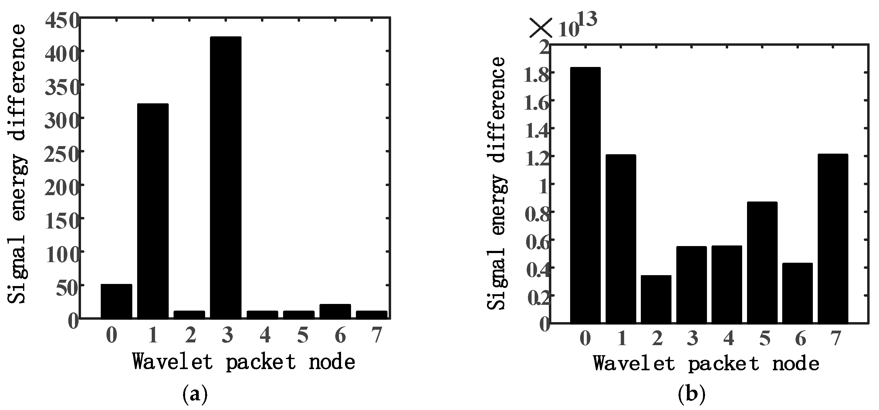
The current signal and the radial electromagnetic force signal of the normal motor and the broken bar fault motor were decomposed by the three-layer wavelet packet using a db5 wavelet basis. The signal energy of each node in the third layer was calculated. The difference of signal energy under each node was compared one by one, and the energy difference diagrams of the current and the radial electromagnetic force signal were obtained, as shown in
Figure 5.
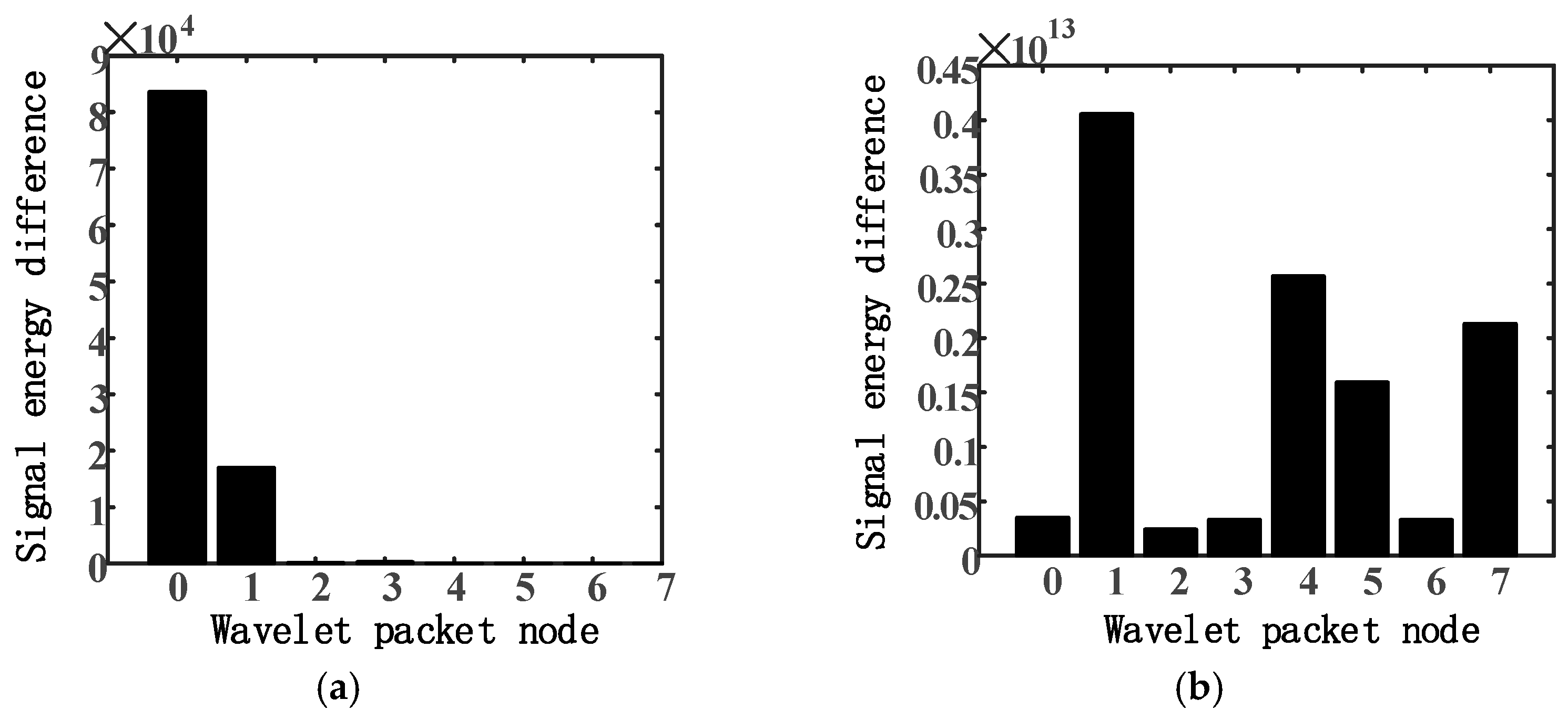
The current signal and the radial electromagnetic force signal of the air gap eccentric fault motor were decomposed by the three-layer wavelet packet and the signal energy of each node in the third layer was calculated. The signal energy under each node was compared with the signal energy of the corresponding frequency band of the normal motor one by one, and the energy difference diagrams of the current and the radial electromagnetic force signal were obtained, as shown in
Figure 6.
The current signal and the radial electromagnetic force signal of the stator inter-turn short-circuit fault motor were decomposed by the three-layer wavelet packet and the signal energy of each node in the third layer was calculated. The signal energy under each node was compared with the signal energy of the corresponding frequency band of the normal motor one by one, and the energy difference diagrams of the current and the radial electromagnetic force signal were obtained, as shown in
Figure 7.
According to the results of the wavelet packet energy analysis, the motor fault information was mainly contained in the first, second, and fourth frequency bands of the third-layer wavelet packet of the current signal, and in the first, second, fourth, fifth, and eighth frequency bands of the third-layer wavelet packet of the radial electromagnetic force signal. Therefore, the energy of the above eight frequency bands was selected as the input vector of the BP neural network. The neural network output layer externally outputs the results of the network training. As the identification and classification of motor faults were involved, the output layer corresponded to the four operating conditions of the submersible motor (specifically: 1000 corresponded to normal operation; 0100 corresponded to the rotor broken bar fault; 0010 corresponded to the air gap eccentric fault; and 0001 corresponded to the stator inter-turn short-circuit fault).
For the design of the hidden layer neurons, the number of hidden layer nodes is generally determined by an empirical formula, as shown in Equation (6).
In Equation (6), m is the number of the input layer nodes (m = 8), s is the number of the hidden layer nodes, and n is the number of the output layer nodes (n = 4); k is a constant between 1 and 10.
The number of the hidden layer nodes was selected from 5 to 14 in turn to establish the three-layer neural network model. The activation function of the hidden layer was the ‘tansig’ function, and the activation function of the output layer was the ‘purelin’ function. The training algorithm was the ‘Levebberg-Marquardt’ algorithm with high accuracy and fast convergence speed. The training was completed when the training times of the BP neural network reached 2000 times or the training error reached 0.001. For each operating condition, 80 groups of data were selected as training samples and 35 groups of data were selected as test samples. The accuracy of the motor pattern recognition under a different number of the hidden layer nodes is shown in
Table 3. It can be observed that when the number of hidden layer nodes was 13, the accuracy of the motor pattern recognition was higher.
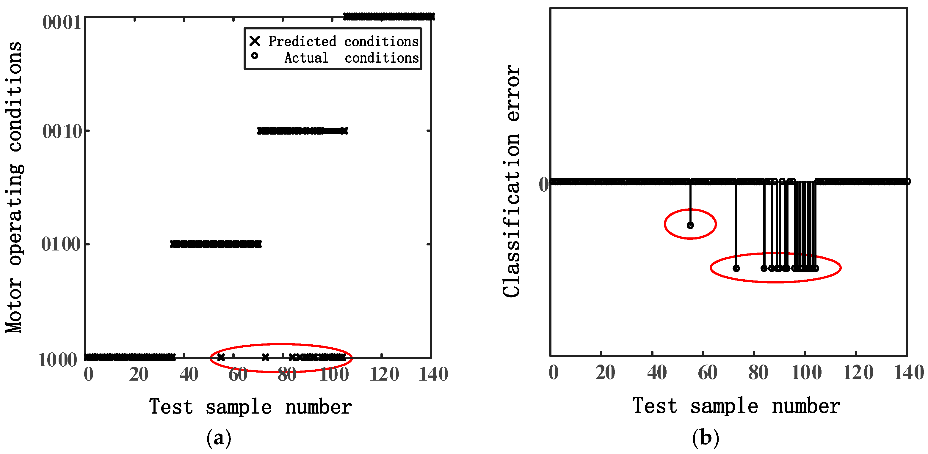
The results of the motor fault pattern recognition are shown in
Figure 8 (specifically: 1000 corresponded to normal operation; 0100 corresponded to the rotor broken bar fault; 0010 corresponded to the air gap eccentric fault; and 0001 corresponded to the stator inter-turn short-circuit fault). Among the 140 test samples, 17 samples were misjudged, and the accuracy of the motor fault pattern recognition was 87.86%.
As the initial weights and thresholds of the BP neural network are randomly generated, the model converges to different results due to different initial parameters, and the neural network has low stability and identification accuracy. In this paper, the genetic algorithm was further used to optimize the initial weights and thresholds of the BP neural network, and the initial parameters suitable for the neural network were selected by an individual fitness function to further improve the accuracy of pattern recognition.
The fitness function was set as the reciprocal of the root mean square error between the actual output and the expected output of the BP neural network. Individuals in the initial population evaluated their performance through the fitness function, and gradually improved the fitness function value through selection, crossover, and mutation operations. After some genetic generations, the optimal solution of the problem was obtained. The variation trend of fitness function values in the process of population evolution is shown in
Figure 9.
The optimized initial weights and thresholds were substituted into the BP neural network model for training and testing. The motor pattern recognition results are shown in
Figure 10. Among the 140 test samples, 10 samples were misjudged, and the accuracy of the motor fault pattern recognition was 92.86%. The same training and test data were selected to perform repeated experiments on the above two BP neural network models for five times, and the comparison of motor pattern recognition accuracy was shown in
Table 4. Comprehensive analysis of
Figure 8 and
Figure 10, and
Table 4 showed that the accuracy of the motor pattern recognition was significantly improved by the BP neural network model optimized by the genetic algorithm.
5. Discussion
The reliable operation of the electric submersible pump system is not only directly related to the oil and gas production and economic benefits of the offshore platform, but it also determines the primary energy supply required for the normal operation of the offshore platform. In order to overcome the shortcomings of the existing monitoring system, such as the poor purpose of fault diagnosis and the difficulty of equipment maintenance and replacement, and improve the operation reliability of the submersible motor, a motor fault diagnosis method based on multi-signal fusion was proposed.
In this paper, the method of the fusion correlation analysis of the stator current and radial electromagnetic force was adopted to reliably diagnose motor faults. Comparing the fusion correlation spectrums (see
Figure 2) with current signal spectrums (see
Figure 3) and radial electromagnetic force signal spectrums (see
Figure 4) based on the Fourier transform, the problem of unreliability for diagnosing motor faults using a single signal was effectively solved. After obtaining the normal and various fault samples of the motor, according to the different energy distribution of the wavelet packet node of the current signal and the radial electromagnetic force signal under different operating conditions, the abnormal frequency band energy was further extracted to construct the fault feature vectors. The training and testing of samples were carried out by the BP neural network and GA-BP neural network, respectively. The results showed that the BP neural network, optimized by the genetic algorithm, had a higher accuracy in fault pattern recognition of the submersible motor (see
Table 4). The accurate monitoring and fault prevention of the electric submersible pump was realized.
In practical engineering applications, in the initial operation stage of the electric submersible pump there are few fault samples; therefore, it is more reliable to diagnose motor faults by the fusion correlation spectrum, which further provides samples for the BP neural network training. Based on this, the fault pattern recognition of the submersible motor can be carried out. The maintenance plans are formulated in combination with the production tasks of the offshore platform, and the failure shutdown loss is minimized through reasonable scheduling, so as to realize the intelligent monitoring and automatic diagnosis of the submersible pump of the offshore platform.
Furthermore, the fault-monitoring method of electric submersible pumps can be extended to other loads of the same type on offshore platforms, such as compressors and water injection pumps, etc., which account for a large proportion of loads on offshore platforms and adopt the same type of motors. Therefore, this will further reduce equipment failure rates and reduce natural gas wastes, which improve the reliability and comprehensive energy efficiency of the power system of offshore platforms from the equipment level. In addition, the new intelligent algorithms to improve the accuracy of fault pattern recognition and the diagnosis of other motor faults (such as bearing faults, partial discharge faults, and motor overheating, etc.) should be further studied.


