Article

Optimized EMS and a Comparative Study of Hybrid Hydrogen Fuel Cell/Battery Vehicles

1
Ecole Centrale Nantes—LS2N (Laboratoire des Sciences du Numérique de Nantes), 1 Rue de la Noë, CEDEX 3, 44000 Nantes, France
2
Department of Industrial Electronics and Control Engineering, Faculty of Electronic Engineering, Menoufia University, Menouf 32952, Menoufia, Egypt
3
Electrical Engineering Department, Université de Technologie de Compiègne, Heudiasyc CNRS, 60200 Compiègne, France
*
Author to whom correspondence should be addressed.
Energies 2022, 15(3), 738; https://doi.org/10.3390/en15030738
Submission received: 4 November 2021 / Revised: 20 December 2021 / Accepted: 21 December 2021 / Published: 20 January 2022
(This article belongs to the Topic Multi-Energy Systems)

Abstract

:
This paper presents a new Fuel Cell Fuel Consumption Minimization Strategy (FCFCMS) for Hybrid Electric Vehicles (HEVs) powered by a fuel cell and an energy storage system, in order to minimize as much as possible the consumption of hydrogen while maintaining the State Of Charge (SOC) of the battery. Compared to existing Energy Management Strategies (EMSs) (such as the well-known State Machine Strategy (SMC), Fuzzy Logic Control (FLC), Frequency Decoupling and FLC (FDFLC), and the Equivalent Consumption Minimization Strategy (ECMS)), the proposed strategy increases the overall vehicle energy efficiency and, therefore, minimizes the total hydrogen consumption while respecting the constraints of each energy and power element. A model of a hybrid vehicle has been built using the TruckMaker/MATLAB software. Using the Urban Dynamometer Driving Schedule (UDDS), which includes several stops and accelerations, the performance of the proposed strategy has been compared with these different approaches (SMC, FLC, FDFLC, and ECMS) through several simulations.

1. Introduction

Currently, as the levels of air pollution caused by the consumption of fossil fuels reach alarming levels, a less polluting fuel source is being considered. Hydrogen has good characteristics to become the fuel of the future such as a high calorific value and clean combustion without producing pollutants, but hydrogen fuel cell technology has not yet been mastered. In 2014, although hydrogen-powered cars and buses began to hit the streets, the technology is not yet fully controlled [1].
A Hydrogen-powered Fuel Cell (HFC) is a non-polluting energy source that generates electricity through the chemical reaction of hydrogen and oxygen. These must be continuously fed to the Fuel Cell (FC) so that it can provide the electricity requirements of the load. In on-board applications, the hydrogen is usually stored in the system, while the oxygen is obtained from the atmosphere by a compressor. Due to the mechanical time constant of the compressor, the HFC system is characterized by a slow response time to load changes, and an auxiliary energy source, such as batteries or supercapacitors, is used to support it in the energy requirements of the load [2,3].
In the last few decades, there has been much research on new transport solutions due to the emission reduction objectives, among which Hybrid Electric Vehicles (HEVs) based on FCs are becoming an attractive technology. Energy management in these vehicles allows for improved fuel economy (hydrogen in this case), which is a very promising solution due to its high mass and volume energy density compared to other polluting sources such as gasoline and diesel. Hydrogen represents a non-toxic, non-polluting fuel with zero emissions, where the combustion only releases water [4].
The future of sustainable transportation is closely linked to the development of these vehicles. Indeed, these vehicles are much quieter, non-polluting, and more efficient than vehicles based on Internal Combustion Engines (ICEs) [5]. However, the use of hydrogen in a running vehicle poses problems: the need for a storage system, the power electronics converters, the choice of the traction motor, and finally, the management of the energy flows. This latter corresponds to the subject of study proposed in this paper, which aims to improve the consumption of the fuel while respecting the constraints imposed by the sources. The FCs are high-current and low-voltage sources. In order to use them in electric vehicle powertrains, it is necessary to use adapted static converters in order to increase the operating voltage. The global optimization of these powertrains requires the hybridization of the battery using an Energy Storage System (ESS) [6].
A control strategy, in the field of hybrid vehicles, is an algorithm whose objective is to regulate the power distribution coming from the different propulsion parts. The considered input data are the operating conditions of the vehicle such as the speed, acceleration, or torque requested by the driver. The output data recovered can be the activation or non-activation of certain components, the increase or reduction of the power output, or the modification of the operating ranges [7]. An energy management strategy can be implemented to satisfy different demands. The most common ones are to ensure the driver’s power demand, to maintain the State Of Charge (SOC) of the battery, to reduce the number of starts, to optimize the efficiency of the drive train, or to reduce fuel consumption and pollutant emissions. In general, a compromise must be found to achieve several of these objectives simultaneously [8,9]. The strategy varies according to the type of vehicle and the type of engine. Indeed, if we consider Hybrid Electric Vehicles (HEVs), the objective is to have a final SOC equal to the initial SOC. If we consider a Plug-in-HEV (PHEV), it is preferable to recharge the battery from the grid rather than from the engine. Therefore, the final SOC should be as close as possible to the minimum tolerated threshold. A typical method is to run the vehicle in full electric mode until the minimum threshold is reached and then maintain the SOC. This method is called Charge Depleting/Charge Sustaining (CD/CS). However, it is not the most suitable method [10,11,12]. To obtain an optimal solution, the principle consists of progressively discharging the battery and reaching the minimum at the end of the trip [11]. This method is often found in the literature under the term blended mode. C. Silva et al. [13] studied the factors of PHEVs affecting the fuel consumption and emissions of this type of vehicle. Recently, with the development of on-board systems in cars, it is possible to access many other parameters. Technologies such as GPS, the Geographical Information System (GIS), and the Intelligent Transport System (ITS) make it possible to define a route and observe the traffic conditions in real time [11]. Several strategies need to know the cycle to work, but some can be used without prior knowledge. In general, these strategies have been parameterized on a predefined cycle, and their efficiency is better on this one. Based on this observation, several works have set up cycle recognition strategies, which use data from the present and the past to determine the appropriate strategy [14,15,16]. Some studies have also been interested in cycle prediction, using for example Markov chains [17,18,19,20]. In this case, the efficiency of the strategy will depend directly on its ability to predict future events. The integration of available information while using new technologies therefore appears to be an interesting way of reducing emissions and consumption [21,22]. Management strategies can be broken down into two main families, rule-based methods and optimization methods. There are many studies that have been conducted on each of these two families. Reference [23] provided an overview of the existing control strategies. This allows us to have an indication of the methods that have been studied. In [24,25], the EMS based on deterministic rules or based on fuzzy logic or Neural Networks (NNs) was detailed. Similarly, the optimization methods based on Model Predictive Control (MPC) to solve the energy management problem online were presented in [26]. An EMS based on the Pontryagin Minimum Principle (PMP) was introduced as an optimal control solution [27,28]. The global optimization requires the driving profile to be known a priori. Therefore, the results are only valid in the laboratory, but they can be used as a basis for comparison with other real-time strategies. A real-time optimization algorithm called the Equivalent Consumption Minimization Strategy (ECMS) was also developed in [29,30,31,32,33,34,35]. It introduces the concept of equivalent consumption. A MATLAB model was implemented for the study of this algorithm, which was subsequently developed using Stateflow on the hybrid vehicle model.
In this paper, a new Fuel Cell Fuel Consumption Minimization Strategy (FCFCMS) is proposed and compared with existing EMSs (such as the well-known State Machine Strategy (SMC), Fuzzy Logic Control (FLC), Frequency Decoupling and FLC (FDFLC), and the Equivalent Consumption Minimization Strategy (ECMS)). The proposed strategy is to minimize the hydrogen consumption of the fuel cell during a vehicle run, while respecting the constraints of the power of the fuel cell and the SOC of the ESS. The model of a hybrid vehicle and the performance of the proposed strategy is compared with these different approaches (SMC, FLC, FDFLC, and ECMS) through TruckMaker/MATLAB software
This paper is organized as follows: In Section 2, the problem formulation of multi-source energy management is presented. In Section 3, the modeling of the hydrogen fuel cell/battery hybrid vehicle is presented. Section 4 presents the proposed hybrid EMS. Finally, Section 5 presents the results on different driving cycles by applying the different methods. Conclusions and future prospects are presented in Section 6.

2. Formulation of the Optimization Problem

The problem of energy management consists of finding the best distribution of power among the energy sources of the system. The presence of the ESS introduces additional degrees of freedom in the supply of the required power. However, this distribution must satisfy the power demand of the Electric Motor (EM) and respect the operating constraints (power of the FC, define the SOC of the battery). The HEV considered in this paper has three energy sources, as illustrated in Figure 1. The energy management problem can be formulated as a dynamic optimization problem in which the system, represented as a dynamic Equation (1), is controlled in order to minimize a cost criterion (2) by respecting equality constraints (3) and inequality constraints (4) [36].
x ˙ ( t ) = f ( x ( t ) , u ( t ) , t )
t o t f Ψ ( x ( t ) , u ( t ) , t ) d t
φ ( x ( t ) , u ( t ) , t ) = 0
ϕ ( x ( t ) , u ( t ) , t ) 0
where x ( t ) represents the state variables and u ( t ) the control variables.

2.1. Overall Multi-Criteria Optimization Formulation

The overall objective of the developed algorithms is to optimize the energy distribution among the energy sources in order to minimize the fuel cell hydrogen consumption, while respecting the constraints of the power limits of the fuel cell and the SOC of the ESS. The most used criterion is the fuel consumption (fuel for thermal engines, hydrogen for FCs, etc.). This criterion is also called the cost function and is expressed as (2) [6]. In our study, we consider that the state variable is the SOC of the battery, and by choosing the power supplied by the FC as the control variable, the equation governing the dynamics of the system is in this case [37,38,39]:
S O ˙ C = i Q b a t , i b a t = V b a t V b a t 2 4 R b a t P b a t 2 R b a t ,
where Q b a t , P b a t , V b a t , and R b a t are the capacity, power, voltage, and resistance of the battery, respectively. On the other hand, the hybrid system must ensure the instantaneous power demand, which results in the following equality constraint [40]:
P d e m a n d = P F C + P b a t
where P d e m a n d is the power demanded and P F C is the fuel cell power.

2.2. The Constraints

The design of the hybrid system’s components imposes maximum and minimum limits on the power exchanged and the energy levels that can be reached. These limits form the inequality constraints (4), expressed as follows [41]:
P F C , m i n P F C ( k ) P F C , m a x
Δ P F C , d r o p d P F C ( k ) d t Δ P F C , r i s e
S O C m i n S O C S O C m a x
where P F C , m a x and P F C , m i n are respectively the maximum and minimum power supplied by the FC and S O C m a x and S O C m i n the maximum and minimum SOC that can be reached by the battery. Knowing that the response time of the FC is large compared to other energy sources, the HEV will not be able to withstand certain slopes of charge power (accelerations). To remedy this problem, the battery will provide a power whose maximum slope will not exceed a value to be determined (at the rise rate Δ P F C , r i s e and at the drop rate Δ P F C , d r o p of the FC power slope). Finally, an additional condition is imposed on the system in order to guarantee the maintenance of the battery’s SOC. In this respect, we considered that the SOC of this element at the end of the studied time horizon is equal to its initial state [41]:
S O C ( t o ) = S O C ( t f )
where S O C ( t o ) and S O C ( t f ) are the initial value and the final value of the SOC.

2.3. The Optimization Criteria

The objective of optimal control applied to energy management is the minimization of fuel consumption in a time interval [ t o ;t f ] on a given mission profile. This amounts to finding at each instant the power to be requested from the FC, in order to minimize the energy consumed from the fuel tank in this interval while verifying the constraints (7)–(10). The energy consumed from the fuel tank can be expressed as a function of the net power delivered by the cell and its total effort, so the cost function to be minimized is expressed by the following equation [42]:
Ψ ( x ( t ) , u ( t ) , t ) = P F C η F C ( P F C ) + ( S O C ( t o ) S O C ( t f ) ) 2
Thus:
J = t o t f P F C η F C ( P F C ) + ( S O C ( t o ) S O C ( t f ) ) 2
The FC efficiency ( η F C ) can be determined by [41]:
η F C = 2 V b a t F N c e l l Δ h
where F is the Faraday constant (in A s / m o l ) and N c e l l is the number of fuel cells. Let us introduce the Hamiltonian applied to the system defined by the following equation:
H ( x ( t ) , u ( t ) , t ) = Ψ ( x ( t ) , u ( t ) , t ) + λ ( x ( t ) , u ( t ) , t )
with,
λ ˙ ( t ) = H ( x * ( t ) , u * ( t ) , λ ( t ) ) x = 2 ( x ( t ) x ( t o ) )
where * means the optimal Hamiltonian solution.
λ ( t ) = λ o 2 t o t f ( x ( t ) x ( t o ) ) d t
where λ o is the initial value of λ . Therefore, the optimization problem consists of finding the values of the power demanded at the FC that allows respecting the condition of maintaining the SOC with the minimization of the Hamiltonian function, as indicated by the following equation:
P F C * = a r g m i n H ( x * ( t ) , u * ( t ) , λ ( t ) )
For the implementation of the algorithm, the driving cycle is known a priori, which gives us the values of the final time, as well as the values of the initial and final load states; what remains to be found is the initial value of the adjoint state (the Lagrangian multiplier), since we have a unique value that is suitable for an optimal trajectory to maintain the SOC inside the required constraints. A search was performed by implementing a dichotomy algorithm using a graphical approach. Nevertheless, this value is not totally exact, and it changes with the driving cycle and the initial SOC of the storage element.

2.4. Hydrogen Consumption and Overall Efficiency

To present the optimization-based energy management strategies, first, the equation that defines the hydrogen consumption must be determined. The energy consumed from the fuel tank can be expressed as a function of the net power delivered by the cell ( P F C ) and the total efficiency of the generator set ( η o v e r a l l ), according to the following equation.
W H 2 [ g / s ] = P F C η F C Δ H
where the calorific value Δ is a property of the fuels whose value depends on the state of the water produced in the chemical reaction (liquid or gas). Then, if we perform the numerical integration, the hydrogen consumption results are given by:
C o n s H 2 [ g / s ] = t o t f P F C η F C Δ H
The overall efficiency ( η o v e r a l l ) is given by [43]:
η o v e r a l l = P d e m a n d P F C i n + P b a t i n + P S C i n
where P F C i n , P b a t i n , and P S C i n are the fuel cell power (input of the DC/DC converter), battery power (input of the DC/DC converters), and supercapacitor power, respectively.

2.5. Global Optimization

If the driving profile is known a priori, a global optimization method can be used to determine the optimum of (19). Thus, the minimization of the consumption is equivalent to determining the power profile of the FC that produces the minimum hydrogen consumption to achieve the driving profile. The objective function to be optimized is therefore:
C o n s H 2 [ m i n ] = M i n 0 t f P F C ( t k ) Δ t k = M i n ( P F C ( t 0 ) Δ t 0 + + P F C ( t f ) Δ t f )
with the constraints given in (7) and (9) and:
Δ S O C = S O C ( t f ) S O C ( t o ) = 0 t f P S C ( t k ) . Δ t k = 0
Therefore, Equation (6) gives the power balance, but (7) and (9) limit the power of the FC and the SOC of the battery, while (22) indicates that the energy balance of the ES must be zero at the end of the drive cycle to ensure that the final SOC of the battery is equal to the initial SOC.

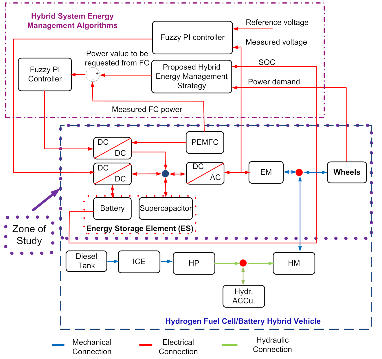
3. Modeling of the Hydrogen Fuel Cell/Battery Hybrid Vehicle

The studied vehicle structure (cf. Figure 1) consists of Proton Exchange Membrane Fuel Cells (PEMFC) as the main energy source connected to a step-up DC/DC converter and the ESS connected to a bi-directional step-down DC/DC converter, a DC bus connected via a DC/AC converter that supplies the mechanical traction. The power converters of the chopper type or direct current (DC/DC) and inverter or DC/AC converter types are used to connect the vehicle’s electrical power devices, namely the electrical machinery, the FC, and the ES. The vehicle’s electrical architecture specifies how the connection is made. The DC/AC converter transforms the power in the DC buses into AC power to the Electric Motor (EM) and controls the traction torque of the motor. In addition, it must be reversible to allow energy recovery during braking. The DC/DC converters control the power distribution between the FC and the ES. They allow adapting the voltages of the FC and the ES to the DC bus and limiting their currents. The structure of the studied hybrid fuel cell vehicle is shown in Figure 1. SimPowerSystems includes already built models of the FC, battery, and supercapacitor, and the formulas determined for these components help in understanding them.

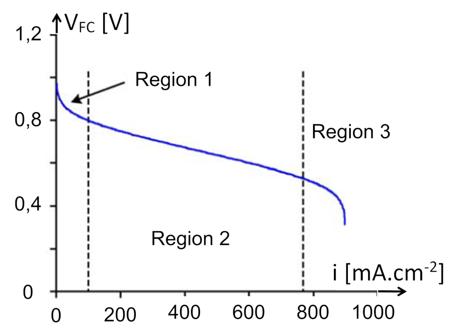
3.1. The Static Model of PEMFC

Many works, such as [44,45,46,47,48,49], have proposed a static model describing the polarization curve of the PEM cell (cf. Figure 2) [50] as the sum of four terms: the theoretical open-circuit voltage E, the activation surge voltage V F C (or activation drop: Region 1 in Figure 2), the ohmic surge voltage Vohm (or ohmic drop: Region 2), and the concentration surge voltage (or concentration drop: Region 3) [48].
This voltage–current characteristic fuel cell comportment can be defined as follows [51]:
V F C = E A l o g ( I F C + i n i o ) R m ( I F C + i n ) + B l o g ( 1 I F C + i n i L )
where E is the reversible no loss voltage of the fuel cell; I F C the delivered current; i o the exchange current; A the slope of the Tafel line; i L the limiting current; B the constant in the mass transfer term; i n the internal current; R m the membrane and contact resistances.

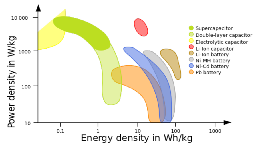
3.2. The Energy Storage Element

Two types of ESs are considered in the hybridization of vehicles: batteries and supercapacitors. Figure 3 shows the differences in the power and energy of some types of capacitors and batteries. The specific energy represents how much electrical energy per unit of mass can be stored by an energy source, while the specific power represents how much power per unit mass can be supplied by an energy source. The specific power also represents the ability of the source to provide or recover energy. The higher the specific power, the faster the source will supply or recover energy.

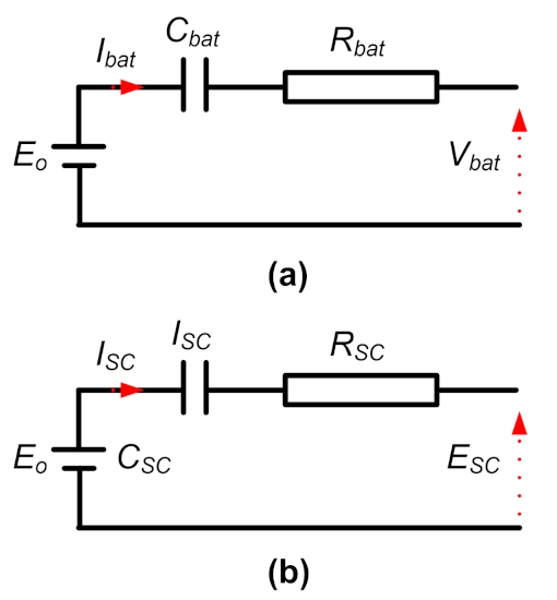
3.2.1. The Battery Model

Several battery models found in the literature use a simple model (cf. Figure 4a). This includes an electromotive force modeling the open circuit voltage of the battery, a capacitor modeling the internal capacity of the battery, and an internal resistance.
Thus, we have:
V b a t = E o R b a t I b a t V c
The SOC is defined as the ratio of the charge stored in the battery to the maximum charge capacity Q b a t :
d ( S O C ) d t = I b a t Q b a t
In order to express I b a t , it should be noted that the instantaneous power delivered by the battery at load is:
P b a t = I b a t V b a t
We also determine the SOC of the battery by:
S O C = S O C ( 0 ) 1 C b a t I b a t d t
The SOC can be expressed according to the following equation:
d ( S O C ) d t = V b a t V b a t 2 4 R b a t P b a t 2 R b a t Q b a t

3.2.2. The Supercapacitor

Unlike the battery, the SC is mainly a power source with a low energy capacity. The energy stored in the SC is given by the following equation:
E S C = 1 2 C S C E o 2
where E o is the voltage behind the impedance R S C in the electrical diagram of the SC (cf. Figure 4b) and C S C is the capacitance of the S C in Farads (F).

3.3. DC/AC and DC/DC Converter Models

The power converters allow adapting the currents and voltages between two electrical devices. The different types of converters are classified according to the type (AC or DC) and the characteristics of the electrical energy. Moreover, depending on the direction of the currents and voltages, the converters can have one or four according to the required current and voltage reversibilities. Finally, the converters have a local control, which generally integrates the current, voltage, and/or power current limitations, thus ensuring partial protection of the devices to which it is connected. The DC/DC converter and DC/DC converter are represented by an average-value model.

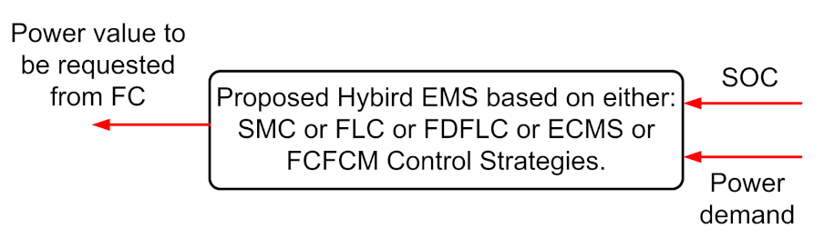
4. Hybrid System Energy Management Algorithms

This section presents the strategies and corresponding algorithms for the energy management of an HEV. The goal of power management in a hybrid FC HEV (FCHEV) is to determine the optimal power flow between the FC generator and the storage element in order to provide the power demanded by the load within the operating constraints and low hydrogen consumption, as well as providing high overall system efficiency. The energy management algorithms or strategies for a hybrid vehicle can be classified as given in [41]. Thus, we can divide the algorithms based on deterministic rules, based on fuzzy rules, real-time online optimization, and offline global optimization.
In this section, we develop rule-based algorithms, as well as an EMS based on optimization. The desired characteristic of the algorithms is the minimization of the hydrogen consumption during a given cycle. Moreover, the final SOC of the battery and supercapacitor should be equal to its initial SOC, which means that the balance of energy that the ES has gained or lost during the driving cycle must be zero at the end of the driving cycle. Thus, each of the algorithms to be performed will determine the reference current of the FC converter in the vehicle diagram shown in Figure 1, which minimizes the fuel consumption while respecting the operating constraints. In the case that the algorithm calculates a reference power, this will be transformed into a reference current. The proposed FC/battery/supercapacitor hybrid vehicular system shown in Figure 1 was implemented in MATLAB and SimPowerSystems software packages.

4.1. EMS Based on the State Machine Strategy

An EMS based on the State Machine Strategy (SMC) is based on [24] to distribute the required power between the fuel cell and the battery in order to maximize the efficiency of the system. It is a deterministic method based on rules that can contain many operating states to control the flow of energy between the different components of a hybrid fuel cell system [53]. Its implementation consists of eight states, as presented in Table 1. These rules are derived using the approach proposed in [54] and are based on the operational limits of the fuel cell and the battery in the system, the power demanded ( P d e m a n d ) by the vehicle, and the SOC of the battery, where P F C , m a x , P F C , m i n , P F C [ r e q ] , and P F C [ o p t ] are respectively the maximum, minimum, requested, and optimal power supplied by the FC and P b a t , m i n is the minimum power of the battery.
The power of the fuel cell is determined based on the SOC range of the battery and the load power. The implementation scheme is shown in Figure 5. Among the main drawbacks of this method is the need to take into account the control of the hysteresis (cf. Figure 6) during the switch between states, which affects the response of the EMS to change it in power demand. As shown in Figure 5, the output of the SMC algorithm is the reference power of the fuel cell, which is obtained by dividing the power determined by the algorithm by the efficiency of the converter, and the inputs are the SOC of the battery and the power demand. From all these data, the hydrogen consumption of the system is evaluated, and and this can be seen by the efficiency curve of the FC. The purpose of this implementation is to verify the guidelines set in the development of the strategy. The aim of the SMC is to decide the FC reference power with the state change. According to the hysteresis cycles for the SOC levels of battery and SCs, as shown in Figure 6, four states designed by the SMC were defined to obtain FC reference power P F C [ r e q ] .
The simulation and validation results are shown in Section 5.

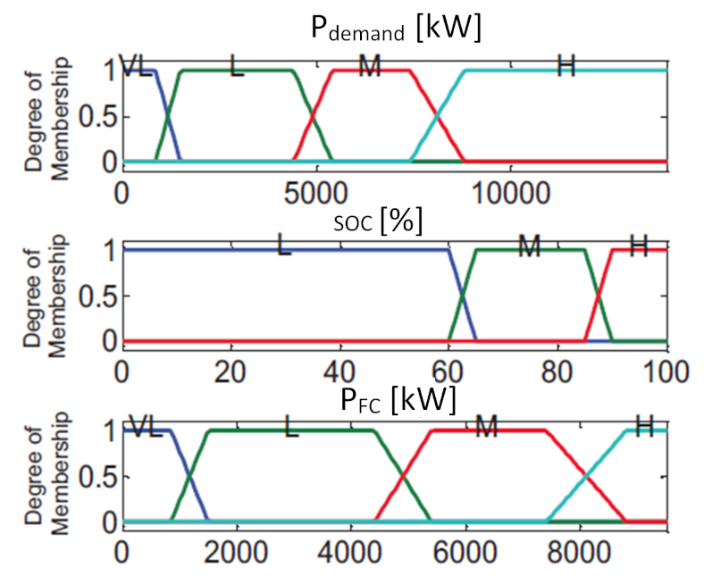
4.2. EMS Based on Fuzzy Logic Rules

Based on the Fuzzy Logic Control (FLC) strategy presented in [25], an EMS was developed. This strategy presents a fast response to changes in the power demand compared to the SMC strategy due to the optimization procedure by adjusting the variation range of membership functions in order to reduce the consumption of hydrogen. The power of the fuel cell was obtained from the membership functions of the requested power and the SOC of the battery, as well as from the set of “if–then” rules. The diagram of EMS based on the FLC strategy is presented in Figure 5.
Trapezoidal membership functions were used, as shown in Figure 7, to design this approach. The rules derived from the decisions of the state machine are shown in Table 2, where H is High, M is Medium, L is Low, and VL is Very Low. Mamdani’s fuzzy inference approach was used with the centroid method for defuzzification [55].

4.3. Strategy Based on Frequency Decoupling and Fuzzy Logic Control

Based on the wavelet transform-FLC strategy [56], the Frequency Decoupling (FD) and FLC (FDFLC) is proposed for power splitting in the studied hybrid HEV. The FDFLC scheme was designed as the rule-based FLC, with the exception of a low-pass filter to cutout the high-frequency component of the power demand. The schematic of this strategy is shown in Figure 5. The FLC was developed based on [25]. This strategy presents better results than the FLC strategy (cf. Section 4.2), because here, the FC is not constantly subjected to variations coming from the power demand. This is due to the low-pass filter, which plays the role of rejecting all the high-frequency signals that could disturb the FC. This strategy, as the FLC strategy (cf. Section 4.2), is very useful in maintaining the SOC, but also ensures that the FC is moderately loaded. When evaluating the hydrogen consumption, both strategies consume almost the same amount of hydrogen.

4.4. Strategy Based in the Minimization of the Equivalent Consumption

This strategy is one of the real-time optimization approach control methods that is based on cost functions and used by many authors [29,30,31,32,33,34]. The objective is to reduce the hydrogen consumption by minimizing the hydrogen consumed by the fuel cell and the equivalent energy required for the final SOC to be equal to the initial SOC of the battery. The equivalent scheme is presented in Figure 5. The optimization problem to determine the equivalent hydrogen consumption can be formulated as follows:
Find the optimal solution:
x = [ P F C , α p , P b a t ]
where P b a t and P F C are the power of the battery and the FC, respectively. α p is the penalty coefficient and is given in (32), which minimizes:
F = [ P F C + α p P b a t ] Δ T
where Δ T is the sampling time, under the constraints of the equalities (6), with:
α p = 1 2 μ ( S O C 0.5 ( S O C m a x + S O C m i n ) ) S O C m a x + S O C m i n
where μ is the SOC balance coefficient, with the limitations (7) and (9),
0 α p 100

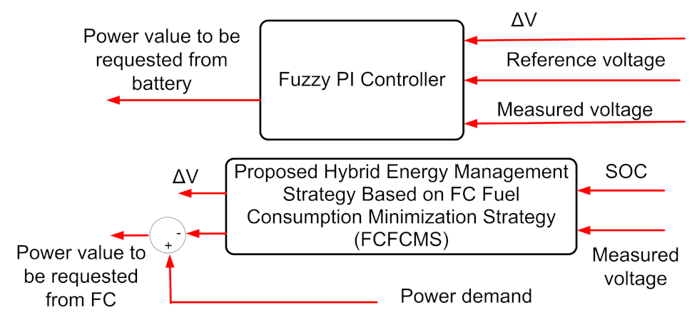
4.5. Proposed FC Fuel Consumption Minimization Strategy

In what follows, an online EMS is proposed. It aims at optimizing the equivalent hydrogen consumption in real time. To do so, we used a real-time optimization technique based on the ECMS. Still having the same objective, which is to minimize the hydrogen consumption in the system, a new optimization concept is introduced based on the maximization of the battery and supercapacitor energies at any given instant, while keeping the battery SOC and DC bus voltage (or supercapacitor SOC) within their operating limits, instead of minimizing the fuel consumption, which requires the evaluation of the equivalent fuel consumption. This strategy is called the FC Fuel Consumption Minimization Strategy (FCFCMS). As shown in Figure 8, the outputs of the FCFCMS algorithm are the battery reference power and the supercapacitor charge/discharge voltage.
The optimization problem to determine the equivalent hydrogen consumption can be formulated as follows:
Find the optimal solution:
x = [ P b a t , Δ V ]
that minimizes:
F = ( P b a t Δ T + 1 2 C S C Δ V 2 )
where Δ V is the supercapacitor charge/discharge voltage and C S C is the rated capacitance of the supercapacitor, with the following constraints:
P b a t Δ T ( S O C S O C m i n ) V b a t Q
within the boundary conditions:
P b a t , m i n P b a t P b a t , m a x V D C , m i n V D C Δ V V D C , m a x V D C
where V D C , m i n and V D C , m a x are the minimum and maximum DC bus voltage ( V D C ) and P b a t , m a x and P b a t , m i n are maximum and minimum power of the battery.

4.6. FC Fuel Consumption Minimization Based on Offline Optimization

If the driving profile is known, (16) must be optimized at each time to achieve the minimum fuel consumption. The optimization problem is defined as follows: The optimal solution is given by:
x = [ P F C ( 1 ) , P F C ( 2 ) , P F C ( 3 ) , , P F C ( n ) ]
with ( k = 1 , 2 , 3 , , n ) and n is the number of samples ( n = T p / Δ T ), with T p being the load profile duration. This minimizes the total fuel cell energy required for the whole power demand profile ( F p ):
F p = k = 1 n P F C ( k ) Δ T
Minimizing F p means minimizing the net fuel cell capacity (in Ampere-hours), hence H 2 consumption, with the following constraints:
y ( k + 1 ) ( S O C ( t o ) S O C m i n ) V b a t Q
k = 1 n P F C ( k ) n × P F C , m i n
with:
y ( k + 1 ) = y ( k ) + ( P d e m a n d ( k ) P F C ( k ) ) Δ T
within the boundary conditions (7), where y ( k ) is the battery energy after k samples. The minimum fuel consumption is obtained from the nominal fuel consumption ( C o n s H 2 [ n o m ] ) as:
C o n s H 2 [ o p t ] = F [ o p t ] C o n s H 2 [ n o m ] k = 1 n P F C [ n o m ] Δ T
where P F C [ n o m ] is the nominal fuel cell power.

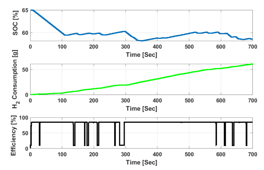
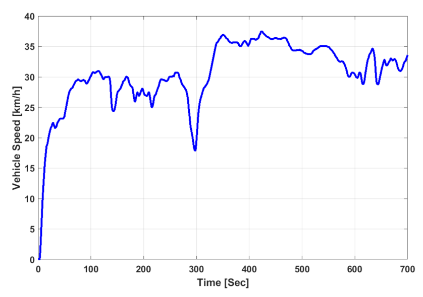
5. Simulation and Validation Results

To evaluate the developed strategy, a simulation using MATLAB software for the simulation of hybrid vehicles on standard cycles was implemented. For comparison purposes, all the EMSs were designed based on the same requirements given in Table 3 with the same initial conditions (SOC initial value is S O C ( t o ) = [ 65 % ], battery, supercapacitor, and FC temperature are 30 ° C, 25 ° C and 40 ° C, respectively). The supercapacitor and FC voltage are 270 V and 52 V, respectively, and were maintained for both cases. In this section, a precise comparative study of the performance of each EMS presented in Section 4 (namely the State Machine Control (SMC), EMS based on FLC, EMS based on Frequency Decoupling and Fuzzy Logic (FDFLC), EMS based on ECMS, and EMS based on FCFCMS), is made. The evaluation of each of the above EMSs was made on an appropriate and long standard driving profile. It corresponds to the Urban Dynamometer Driving Schedule (UDDS), which includes several stops and accelerations. Figure 9 shows this driving profile.
Figure 10, Figure 11, Figure 12, Figure 13 and Figure 14 show the FC power, battery power, and supercapacitor power on the UDDS profile for the EMS based on SMC, FLC, FDFLC, ECMS, and FCFCMS, respectively. The SOC, H 2 consumption, and overall efficiency on the UDDS profile achieved with the HEV are presented in Figure 15, Figure 16, Figure 17, Figure 18 and Figure 19 for the EMS based on SMC, FLC, FDFLC, ECMS, and FCFCMS, respectively.

Discussion

This paper tested the performance of the energy management strategies (ECMS and FCFCMS) based on optimal control compared to three other strategies (SMC, FLC, and FDFLC) while highlighting the results w.r.t. the fuel consumption, SOC, and overall efficiency. These strategies were examined on the UDDS driving profile. The results of this comparison are shown in Table 4.
The main criteria for the performance comparison were: H 2 consumption (g), the SOC (%) of the batteries/supercapacitors, and the overall efficiency (%). From the obtained results, it can be seen that energy management based on optimal control led to a good reduction of the hydrogen consumption while respecting the limits imposed by the sources, a good control of the SOC, and the stability of the FC during its operation. The FLC strategy presented a fast response to changes in the power demand compared to the SMC strategy. FLC provided a quite suitable structure compared to conventional control methods, especially for the systems composed of nonlinear behaviors, where an overall mathematical model is difficult to obtain. As expected, the lowest use of the battery energy was achieved with the frequency decoupling and fuzzy logic scheme, but at the expense of more fuel consumption and lower overall efficiency. In all the considered cases, optimal control-based management had the best performance and did not require a large amount of computation time. The FCFCMS performed slightly better compared to the ECMS in terms of efficiency and fuel consumption. The fact that it is an offline management strategy makes it less feasible except in applications where the driving path is known a priori such as street cars and high-speed roads. The following Table 5 compares the characteristics of the EMS algorithms, where H is High, DM is Difficulty Medium, L is Low, Imp is Implementation, ER is Easy to Realize, Comp is Complicated, and ET is the Execution time.

6. Conclusions

The paper presented a new Fuel Cell Fuel Consumption Minimization Strategy (FCFCMS) for Hybrid Electric Vehicles (HEVs). This strategy depends on the driving path and takes into account several performance criteria such as the slow dynamics of the FC, the reduction of fuel consumption, and good control of the storage element. In order to properly carry out this task, the work was divided into the following steps: (i) the definition of the main formulas that govern the operation of the system components, namely: the FC, the ES (the supercapacitor and the battery), the vehicle and its powertrain; (ii) the modeling of the hybrid vehicle; (iii) the implementation of the control strategies. A model of a hybrid vehicle was built using the TruckMaker/MATLAB software. Using the Urban Dynamometer Driving Schedule (UDDS), which includes several stops and accelerations, the performance of the proposed strategy was compared with these different approaches (SMC, FLC, FDFLC, and ECMS) through simulations. The results of this paper support that the proposed strategy: (i) is simple and more robust to changes of the power demand; (ii) increases the overall vehicle energy efficiency; (iii) minimizes the total hydrogen consumption and respects the constraints of each energy and power elements compared to the strategies based on SMC, FLC, FDFLC, and the ECMS. In a future work, it will be possible to set up an intelligent energy management strategy which will determine in a first step the priority of operation of the batteries and, in a second step, the type of strategies to adopt. This strategy will be further developed around a learning system in order to allow the system to make decisions according to the actual behavior of the system.

Author Contributions

Conceptualization, E.K. and L.A.; methodology, E.K. and L.A.; software, E.K. and L.A.; validation, E.K. and L.A.; formal analysis, E.K. and L.A.; investigation, E.K. and L.A.; resources, E.K. and L.A.; data curation, E.K. and L.A.; writing—original draft preparation, E.K. and L.A.; writing—review and editing, E.K. and L.A.; visualization, E.K. and L.A.; supervision, E.K. and L.A.; project administration, E.K. and L.A.; funding acquisition, E.K. and L.A. All authors have read and agreed to the published version of the manuscript.

Funding

This research received no external funding.

Institutional Review Board Statement

Not applicable.

Informed Consent Statement

Not applicable.

Data Availability Statement

Not applicable.

Conflicts of Interest

The authors declare no conflict of interest.

Abbreviations

HFCHydrogen-powered Fuel Cell
FCFuel Cell
HEVsHybrid Electric Vehicles
ICEInternal Combustion Engine
ESSEnergy Storage System
SOCState Of Charge
CD/CSCharge Depleting/Charge Sustaining
GISGeographical Information System
EMSEnergy Management Strategy
NNNeural Network
MPCModel Predictive Control
PMPPontryagin Minimum Principle
ECMSEquivalent Fuel Consumption Minimization
SEStorage Element
FCSFuel Cell System
EMElectric Motor
PEMFCProton Exchange Membrane Fuel Cells
HPHydraulic Pump
HMHydraulic Motor
SMCState Machine Strategy
FLCFuzzy Logic Control
FDFLCFrequency Decoupling (FD) and FLC
FCFCMSFC Fuel Consumption Minimization Strategy
UDDSUrban Dynamometer Driving Schedule

References

  1. Hwang, H.-Y. Developing Equivalent Consumption Minimization Strategy for Advanced Hybrid System-II Electric Vehicles. Energies 2020, 13, 2033. [Google Scholar] [CrossRef]
  2. Khan, M.J.; Iqbal, M.T. Dynamic Modelling and Simulation of a Fuel Cell Generator, Fuel Cells Special Issue: Modelling of Fuel Cell Systems. Fuel Cells 2005, 5, 97–104. [Google Scholar] [CrossRef]
  3. He, Y.; Miao, C.; Wu, J.; Zheng, X.; Liu, X.; Han, F. Research on the Power Distribution Method for Hybrid Power System in the Fuel Cell Vehicle. Energies 2021, 14, 734. [Google Scholar] [CrossRef]
  4. Fueling the Future Hydrogen Fuel Cell Vehicles in the 21st Century. Available online: http://serc.berkeley (accessed on 1 January 2021).
  5. Chan, C.C.; Bouscayrol, A.; Chen, C.K. Electric, hybrid and fuel cell vehicles: Architectures and modelling. IEEE Trans. Veh. Technol. 2010, 59, 589–598. [Google Scholar] [CrossRef]
  6. Neffati, A. Stratégies de Gestion de l. Énergie Électrique d’un Système Multi-Source: Décision Optimisée pour véHicule éLectrique Hybride. Ph.D. Thesis, Université de Toulouse III Paul Sabatier, Toulouse, France, 2013. [Google Scholar]
  7. Hajimiri, M.H.; Salmasi, F.R. A Fuzzy Energy Management Strategy for Series Hybrid Electric Vehicle with Predictive Control and Durability Extension of the Battery. In Proceedings of the IEEE Conference on Electric and Hybrid Vehicles, Pune, India, 18–20 December 2006; pp. 1–5. [Google Scholar]
  8. Stockar, S.; Marano, V.; Canova, M.; Rizzoni, G.; Guzzella, L. Energy-optimal control of plug-in hybrid electric vehicles for real-world driving cycles. IEEE Trans. Veh. Technol. 2011, 60, 2949–2962. [Google Scholar] [CrossRef]
  9. Wai, R.-J.; Jhung, S.-J.; Liaw, J.-J.; Chang, Y.-R. Intelligent Optimal Energy Management System for Hybrid Power Sources Including Fuel Cell and Battery. IEEE Trans. Power Electron. 2013, 28, 3231–3244. [Google Scholar] [CrossRef]
  10. Gonder, J.; Markel, T. Energy Management Strategies for Plug-In Hybrid Electric Vehicles. In Proceedings of the SAE World Congress, Detroit, MI, USA, 16–19 April 2007; pp. 1–5. [Google Scholar]
  11. Gong, Q.; Li, Y.; Peng, Z.-R. Trip-Based Optimal Power Management of Plug-in Hybrid Electric Vehicles. IEEE Trans. Veh. Technol. 2008, 57, 3393–3401. [Google Scholar] [CrossRef]
  12. Wu, G.; Boriboonsomsin, K.; Barth, M.J. Development and Evaluation of an Intelligent Energy-Management Strategy for Plug-in Hybrid Electric Vehicles. IEEE Trans. Intell. Transp. Syst. 2014, 15, 1091–1100. [Google Scholar] [CrossRef]
  13. Silva, C.; Ross, M.; Farias, T. Evaluation of energy consumption, emissions and cost of plug-in hybrid vehicles. Energy Convers. Manag. 2009, 50, 1635–1643. [Google Scholar] [CrossRef]
  14. Lin, C.-C.; Peng, H.; Jeon, S.; Lee, J.M. Control of a Hybrid Electric Truck Based on Driving Pattern Recognition. In Proceedings of the 2002 Advanced Vehicle Control Conference, Hiroshima, Japan, 9–13 September 2002. [Google Scholar]
  15. Ravey, A.; Blunier, B.; Lukic, S.; Miraoui, A. Control strategy of fuel cell hybrid electric vehicle based on driving cycle recognition. In Proceedings of the 2012 IEEE Transportation Electrification Conference and Expo (ITEC), Dearborn, MI, USA, 18–20 June 2012; pp. 1–5. [Google Scholar]
  16. Recognition, R. Energy Management, and Plughybrid Electric Vehicles. Chalmers Publication Library Benefit of Route Recognition in Energy Management of Plug-In Hybrid Electric Vehicles. In Proceedings of the 2012 American Control Conference (ACC), Montréal, CA, USA, 27–29 June 2012. [Google Scholar]
  17. Johannesson, L.; Asbogard, M.; Egardt, B. Assessing the Potential of Predictive Control for Hybrid Vehicle Powertrains Using Stochastic Dynamic Programming. IEEE Trans. Intell. Transp. Syst. 2007, 8, 71–83. [Google Scholar] [CrossRef]
  18. Serrao, L.; Onori, S.; Rizzoni, G. A comparative analysis of energy management strategies for hybrid electric vehicles. J. Dyn. Syst. Meas. Control. 2011, 133, 031012. [Google Scholar] [CrossRef] [Green Version]
  19. Souffran, F.; Miegeville, L.; Guerin, P. Simulation of RealWorld Vehicle Missions Using a Stochastic Marcov Model for Optimal Design Purposes. In Proceedings of the IEEE Vehicular Power and Propulsion Conference, Chicago, IL, USA, 6–9 September 2011; pp. 1–6. [Google Scholar]
  20. Martinez, C.M.; Hu, X.; Cao, D.; Velenis, E.; Gao, B.; Wellers, M. Energy Management in Plug-in Hybrid Electric Vehicles: Recent Progress and a Connected Vehicles Perspective. IEEE Trans. Veh. Technol. 2016, 66, 4534–4549. [Google Scholar] [CrossRef] [Green Version]
  21. Manzie, C.; Watson, H.; Halgamuge, S. Fuel economy improvements for urban driving: Hybrid vs. intelligent vehicles. Transp. Res. Part Emerg. Technol. 2007, 15, 1–16. [Google Scholar] [CrossRef]
  22. Murphey, Y.L. Intelligent Vehicle Power Management: An Overview. In Computational Intelligence in Automotive Applications; Springer: Berlin/Heidelberg, Germany, 2008; Volume 190, pp. 169–190. [Google Scholar]
  23. Zhang, P.; Yan, F.; Du, C. A comprehensive analysis of energy management strategies for hybrid electric vehicles based on bibliometrics. Renew. Sustain. Energy Rev. 2015, 48, 88–104. [Google Scholar] [CrossRef]
  24. Kamal, E.; Adouane, L. Intelligent Energy Management Strategy Based on Artificial Neural Fuzzy for Hybrid Vehicle. IEEE Trans. Intell. Veh. 2017, 3, 112–125. [Google Scholar] [CrossRef]
  25. Kamal, E.; Adouane, L. Hierarchical energy optimization strategy and its integrated reliable battery fault management for hybrid hydraulicelectric vehicle. IEEE Trans. Veh. Technol. 2018, 67, 3740–3754. [Google Scholar] [CrossRef]
  26. Philippe, C.; Adouane, L.; Thuilot, B.; Tsourdos, A.; Shin, H.-S. Safe and online MPC for managing safety and comfort of autonomous vehicles in urban environment. In Proceedings of the 21st International Conference on Intelligent Transportation Systems (ITSC), Maui, HI, USA, 4–7 November 2018; pp. 300–306. [Google Scholar]
  27. Ouddah, N.; Adouane, L.; Abdrakhmanov, R.; Kamal, E. Optimal energy management strategy of plug-in hybrid electric bus in urban conditions. In Proceedings of the 14th International Conference on Informatics in Control, Automation and Robotics, Madrid, Spain, 26–28 July 2017; pp. 304–311. [Google Scholar]
  28. Kim, K.; Jeong, J.; Min, S.; Yang, H.; Vijayagopal, R.; Rousseau, A.; Cha, S.W. A Component-Sizing Methodology for a Hybrid Electric Vehicle Using an Optimization Algorithm. Energies 2021, 14, 3147. [Google Scholar] [CrossRef]
  29. Ouddah, N.; Adouane, L.; Abdrakhmanov, R. From offline to adaptive online energy management strategy of hybrid vehicle using Pontryagin’s minimum principle. Int. J. Autom. Technol. 2018, 19, 571–584. [Google Scholar] [CrossRef]
  30. Volkan, S.; Metin, G.; Seta, B. A novel ECMS and combined cost map approach for high-efficiency series hybrid electric vehicles. IEEE Trans. Veh. Technol. 2011, 60, 3557–3570. [Google Scholar]
  31. García, P.; Torreglosa, J.P.; Fernandez, L.M.; Jurado, F. Viability study of a FC-battery-SC tramway controlled by equivalent consumption minimization strategy. Int. J. Hydrogen Energy 2012, 37, 9368–9382. [Google Scholar] [CrossRef]
  32. Torreglosa, J.P.; Jurado, F.; García, P.; Fernández, L.M. Hybrid fuel cell and battery tramway control based on an equivalent consumption minimization strategy. Control Eng. Pract. 2011, 19, 1182–1194. [Google Scholar] [CrossRef]
  33. Rodatz, P.; Paganelli, G.; Sciarretta, A.; Guzzella, L. Optimal power management of an experimental fuel cell/supercapacitor-powered hybrid vehicle. Control Eng. Pract. 2005, 13, 41–53. [Google Scholar] [CrossRef]
  34. Kwon, L.; Cho, D.-S.; Ahn, C. Degradation-Conscious Equivalent Consumption Minimization Strategy for a Fuel Cell Hybrid System. Energies 2021, 14, 3810. [Google Scholar] [CrossRef]
  35. Abdrakhmanov, R.; Adouane, L. Dynamic programming resolution and database knowledge for online predictive energy management of hybrid vehicles. In Proceedings of the 14th International Conference on Informatics in Control, Automation and Robotics, Madrid, Spain, 26–28 July 2017; pp. 132–143. [Google Scholar]
  36. Govardhan, O.M. Fundamentals and Classification of Hybrid Electric Vehicles. Int. J. Eng. Tech. 2017, 3, 194–198. [Google Scholar]
  37. Zheng, C.H.; Oh, C.E.; Park, Y.I.; Lim, W.S.; Xu, G. PMP-Based Power Management Strategy of Fuel Cell Hybrid Vehicles Considering Multi-Objective Optimization. Int. J. Precis. Eng. Manuf. 2013, 14, 845–853. [Google Scholar] [CrossRef]
  38. Li, C.Y.; Liu, G.P. Optimal fuzzy power control and management of fuel cell/battery hybrid vehicles. J. Power Sources 2009, 192, 525–533. [Google Scholar] [CrossRef]
  39. Zheng, C.H.; Kim, N.W.; Park, Y.I.; Lim, W.S.; Xu, G. The effect of battery temperature on total fuel consumption of fuel cell hybrid vehicles. Int. J. Hydrogen Energy 2013, 38, 5192–5200. [Google Scholar] [CrossRef]
  40. Feroldi, D.; Serra, M.; Riera, J. Energy Management Strategies based on efficiency map for Fuel Cell Hybrid Vehicles. J. Power Sources 2009, 190, 387–401. [Google Scholar] [CrossRef] [Green Version]
  41. Hankache, W. Gestion Optimisée de l’Énergie Électrique d’un Groupe Électrogène Hybride à Pile à Combustible. Ph.D. Thesis, Université de Toulouse, Toulouse, France, 2008; pp. 36–41. [Google Scholar]
  42. Ouddah, N.; Boukhnifer, M.; Raisemche, A. Two Control Energy Management Schemes for Electrical Hybrid Vehicle. In Proceedings of the SSD Systems, Signals & Devices, Hammamet, Tunisia,, 18–21 March 2013. [Google Scholar]
  43. Wróblewski, P.; Drożdż, W.; Lewicki, W.; Miążek, P. Methodology for Assessing the Impact of Aperiodic Phenomena on the Energy Balance of Propulsion Engines in Vehicle Electromobility Systems for Given Areas. Energies 2021, 14, 2314. [Google Scholar] [CrossRef]
  44. Khan, N.J.; Iqbal, M.T. Dynamic modeling and simulation of a small wind-fuel cell hybrid energy system. Renew. Energy 2005, 30, 421–439. [Google Scholar] [CrossRef]
  45. Kishor, N.; Mohanty, S.R. Fuzzy modeling of fuel cell based on mutual information between variables. Int. J. Hydrogen Energy 2010, 35, 3620–3631. [Google Scholar] [CrossRef]
  46. Shan, Y.; Choe, S.Y. Modeling and simulation of a PEM fuel cell stack considering temperature effects. J. Power Sources 2006, 158, 274–286. [Google Scholar] [CrossRef]
  47. Kamal, E.; Aitouche, A. Fuzzy Observer-Based Fault Tolerant Control Against Sensor Faults for Proton Exchange Membrane Fuel Cells. Int. J. Hydrogen Energy 2020, 45, 11220–11232. [Google Scholar] [CrossRef]
  48. Becherif, M.; Saadi, A.; Hissel, D.; Aboubou, A.; Ayad, M.Y. Static and dynamic proton exchange membrane fuel cell models. J. Hydrocarb. Mines Environ. Res. 2011, 2, 1–9. [Google Scholar]
  49. Ham, S.-W.; Jo, S.-Y.; Dong, H.-W.; Jeongn, J.-W. A simplified PEM fuel cell model for building cogeneration applications. Energy Build. 2015, 107, 213–225. [Google Scholar] [CrossRef]
  50. Zhang, C.; Li, W.; Hu, M.; Cheng, X.; He, K.; Mao, L. A Comparative Study of Using Polarization Curve Models in Proton Exchange Membrane Fuel Cell Degradation Analysis. Energies 2020, 13, 3759. [Google Scholar] [CrossRef]
  51. Larminie, J.; Dicks, A. Fuel Cell Systems Explained, 2nd ed.; John Wiley & Sons: Hoboken, NJ, USA, 2003. [Google Scholar]
  52. Available online: https://commons.wikimedia.org/wiki/File:Energiespeicher3.svg (accessed on 1 October 2021).
  53. Fernandez, L.M.; Garcia, P.; Garcia, C.A.; Jurado, F. Comparison of control schemes for a fuel cell hybrid tramway integrating two DC/DC converters. Int. J. Hydrogen Energy 2010, 35, 5731–5744. [Google Scholar] [CrossRef]
  54. Fernandez, L.M.; Garcia, P.; Garcia, C.A.; Jurado, F. Hybrid electric system based on fuel cell and battery and integrating a single DC/DC converter for a tramway. Energy Convers. Manag. 2011, 52, 2183–2192. [Google Scholar] [CrossRef]
  55. Kamal, E.; Adouane, L.; Abdrakhmanov, R.; Ouddah, N. Hierarchical and adaptive neuro-fuzzy control for intelligent energy management in hybrid electric vehicles. IFAC-PapersOnLine 2017, 50, 3014–3021. [Google Scholar] [CrossRef]
  56. Vural, B.; Boynuegri, A.R.; Nakirn, I.; Erdincn, O.; Balikci, A.; Uzunoglu, M.; Gorgun, H.; Dusmez, S. Fuel cell and ultra-capacitor hybridization: A prototype testbench based analysis of different energy management strategies for vehicular applications. Int. J. Hydrogen Energy 2010, 35, 11161–11171. [Google Scholar] [CrossRef]
Figure 1. Hybrid system configuration and the powertrain power flows (ICE: Internal Combustion Engine, HP: Hydraulic Pump, HM: Hydraulic Motor, EM: Electric Motor).
Energies 15 00738 g001
Figure 2. A typical PEMFC voltage–current curve.
Energies 15 00738 g002
Figure 3. Power vs. energy density [52].
Energies 15 00738 g003
Figure 4. Electrical model of: (a) the battery, (b) the supercapacitor.
Energies 15 00738 g004
Figure 5. Representation of the implementation of the energy management strategy (SMC: State Machine Strategy, FLC: Fuzzy Logic Control, FDFLC: Frequency Decoupling and FLC, ECMS: Equivalent Consumption Minimization Strategy, FCFCMS: FC Fuel Consumption Minimization Strategy).
Energies 15 00738 g005
Figure 6. Hysteresis control.
Energies 15 00738 g006
Figure 7. Membership functions for power demand, SOC, and battery power.
Energies 15 00738 g007
Figure 8. FC Fuel Consumption Minimization Strategy (FCFCMS).
Energies 15 00738 g008
Figure 9. Speed profile of the UDDS standard velocity profile.
Energies 15 00738 g009
Figure 10. Power demand ( P d e m a n d ), FC power ( P F C ), battery power ( P b a t ), and supercapacitor power ( P S C ) for the EMS based on SMC.
Energies 15 00738 g010
Figure 11. Power demand ( P d e m a n d ), FC power ( P F C ), battery power ( P b a t ), and supercapacitor power ( P S C ) for the EMS based on FLC.
Energies 15 00738 g011
Figure 12. Power demand ( P d e m a n d ), FC power ( P F C ), battery power ( P b a t ), and supercapacitor power ( P S C ) for the EMS based on FDFLC.
Energies 15 00738 g012
Figure 13. Power demand ( P d e m a n d ), FC power ( P F C ), battery power ( P b a t ), and supercapacitor power ( P S C ) for the EMS based on the ECMS.
Energies 15 00738 g013
Figure 14. Power demand ( P d e m a n d ), FC power ( P F C ), battery power ( P b a t ), and supercapacitor power ( P S C ) for the EMS based on the FCFCMS.
Energies 15 00738 g014
Figure 15. SOC, H 2 consumption, and overall efficiency for the EMS based on SMC.
Energies 15 00738 g015
Figure 16. SOC, H 2 consumption, and overall efficiency for the EMS based on FLC.
Energies 15 00738 g016
Figure 17. SOC, H 2 consumption, and overall efficiency for the EMS based on FDFLC.
Energies 15 00738 g017
Figure 18. SOC, H 2 consumption, and overall efficiency for the EMS based on the ECMS.
Energies 15 00738 g018
Figure 19. SOC, H 2 consumption, and overall efficiency for the EMS based on the FCFCMS.
Energies 15 00738 g019
Table 1. Power distribution among the different sources of the system for an EMS based on an SMS.
SOC P demand P FC [ req ]
High P d e m a n d < P F C , m i n P F C [ r e q ] = P F C , m i n
High P d e m a n d [ P F C , m i n , P F C , m a x ] P F C [ r e q ] = P d e m a n d
High P d e m a n d P F C , m a x P F C [ r e q ] = P F C , m a x
Normal P d e m a n d < P F C [ o p t ] P F C [ r e q ] = P F C [ o p t ]
Normal P d e m a n d [ P F C [ o p t ] , P F C , m a x ] P F C [ r e q ] = P d e m a n d
Normal P d e m a n d P F C , m a x P F C [ r e q ] = P F C , m a x
Low P d e m a n d < P F C , m a x P F C [ r e q ] = P d e m a n d P b a t , m i n
Low P d e m a n d P F C , m a x P F C [ r e q ] = P F C , m a x
Table 2. Fuzzy logic rules assigned to the stack.
SOC P demand P FC [ req ]
HVLVL
HLL
HMML
HHH
MVLVL
MLL
MMM
MHH
LVLL
LLM
LMH
LHH
Table 3. Energy management design requirements.
Design RequirementsValue
FC power [ P F C , m i n P F C , m a x ] (kW)[1–10]
Energy power [ P b a t , m i n P b a t , m a x ] (kW)[−1.2–4]
Energy SOC [ S O C m i n S O C m a x ] [%][60–90]
DC bus voltage [ V D C , m i n V D C , m a x ] (kW)[250–280]
Table 4. Overall performance obtained for the different studied energy management strategies. SMC: State Machine Strategy, FLC: Fuzzy Logic Control, FDFLC: Frequency Decoupling and FLC, ECMS: Equivalent Consumption Minimization Strategy, FCFCMS: FC Fuel Consumption Minimization Strategy; the initial value is S O C ( t o ) = [ 65 % ].
EMS Strategies SOC ( t f ) (%) H 2 Consumption (g)Overall Efficiency (%)
SMC59.1059.1085.20
FLC62.0160.9284.93
FDFLC62.5061.5084.09
ECMS66.6561.0184.88
ECMS (offline)66.6558.20
FCFCMS58.5758.4085.01
FCFCMS (offline)58.5757.90
Table 5. Comparative table of the characteristics of the SMC, FLC, FDFLC, ECMS, and FCFCMS algorithms.
EMS StrategiesImpSettingET SOC ( t f ) H 2 Consumption
SMCsimpleERLnot satisfiedM
FLCDMCompMsatisfiedM
FDFLCDMCompMsatisfiedThe largest
ECMScomplexDMHsatisfiedM
FCFCMScomplexDMHsatisfiedThe least
Publisher’s Note: MDPI stays neutral with regard to jurisdictional claims in published maps and institutional affiliations.

