Author Contributions
Conceptualization, T.M. and J.L.; methodology, T.M.; software, T.M.; validation, X.Z. and W.W.; formal analysis, B.Z.; investigation, T.M.; resources, J.L.; data curation, X.L.; writing—original draft preparation, T.M.; writing—review and editing, B.Z.; visualization, T.M.; supervision, X.Z.; project administration, J.L.; funding acquisition, J.L. All authors have read and agreed to the published version of the manuscript.
Figure 1.
Diagram of the simplified circuit of the battery-pulse capacitor-based hybrid energy storage system.
Figure 1.
Diagram of the simplified circuit of the battery-pulse capacitor-based hybrid energy storage system.
Figure 2.
Diagram of the simplified circuit of the battery-pulse capacitor charging process.
Figure 2.
Diagram of the simplified circuit of the battery-pulse capacitor charging process.
Figure 3.
The charging current in the charging process.
Figure 3.
The charging current in the charging process.
Figure 4.
Diagram of the simplified circuit of the battery-pulse capacitor freewheeling process.
Figure 4.
Diagram of the simplified circuit of the battery-pulse capacitor freewheeling process.
Figure 5.
The flow chart of the procedures for calculating the total charging time.
Figure 5.
The flow chart of the procedures for calculating the total charging time.
Figure 6.
The flow chart of the procedures for the variable selection.
Figure 6.
The flow chart of the procedures for the variable selection.
Figure 7.
The flow chart of the procedures for the total charging time calculation and comparison.
Figure 7.
The flow chart of the procedures for the total charging time calculation and comparison.
Figure 8.
Calculation results of total charging time corresponding to all the variable vectors in .
Figure 8.
Calculation results of total charging time corresponding to all the variable vectors in .
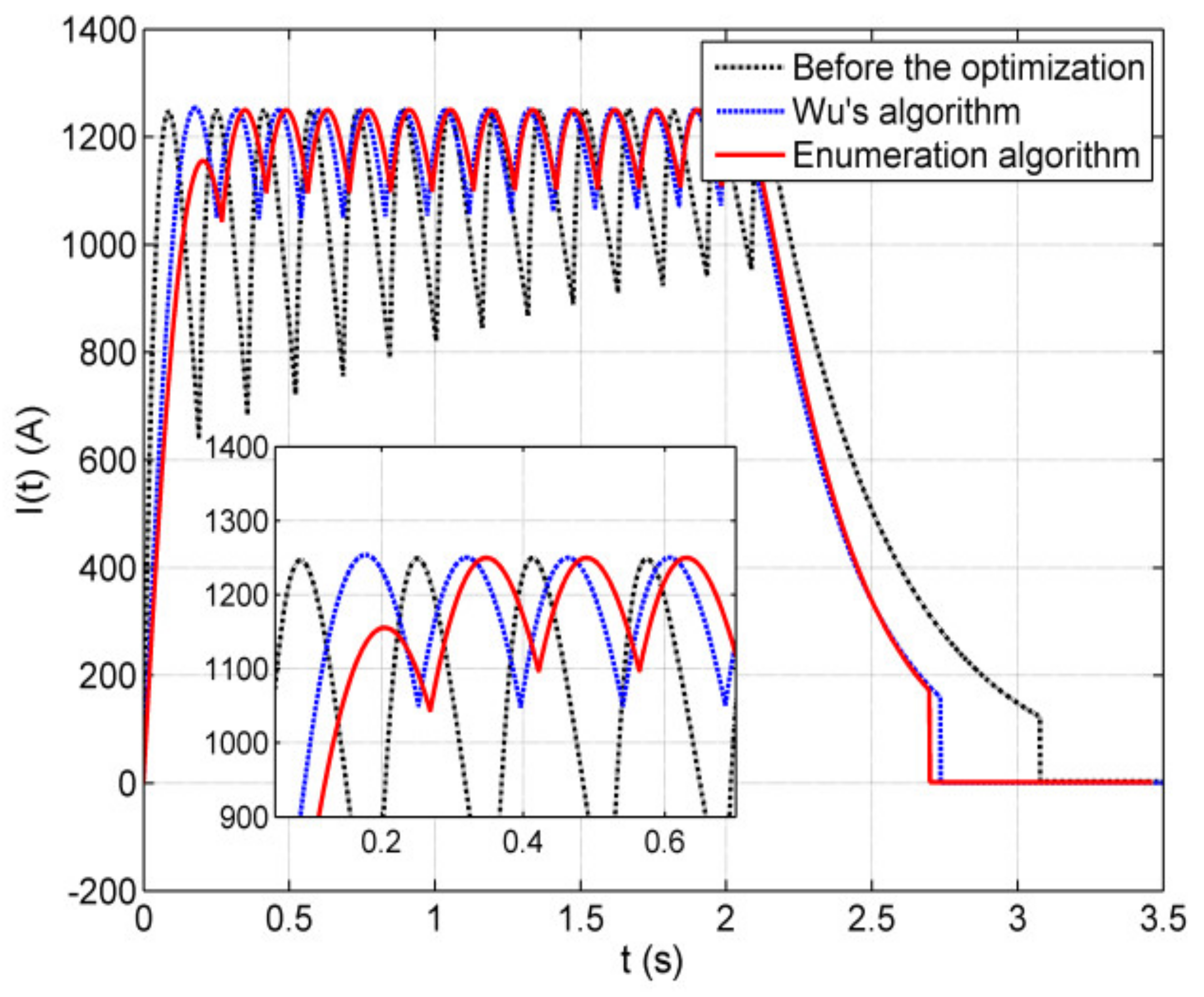
Figure 9.
Charging current-time curves of the pulse capacitor of the two algorithms.
Figure 9.
Charging current-time curves of the pulse capacitor of the two algorithms.
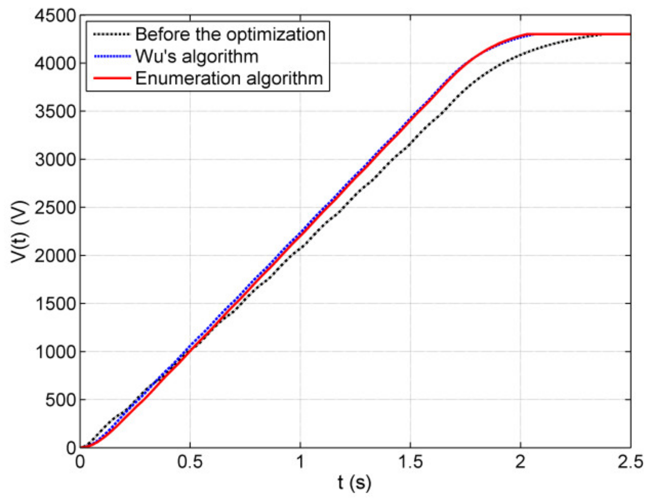
Figure 10.
Charging voltage-time curves of the pulse capacitor of the two algorithms.
Figure 10.
Charging voltage-time curves of the pulse capacitor of the two algorithms.
Figure 11.
The relationship between the first peak value of the charging current and the total charging time for all feasible solutions of the Enumeration algorithm.
Figure 11.
The relationship between the first peak value of the charging current and the total charging time for all feasible solutions of the Enumeration algorithm.
Figure 12.
The relationship between the first peak value of the charging current and the total charging time for the two battery pack structures in the feasible solutions of the Enumeration algorithm, respectively. (a) . (b)
.
Figure 12.
The relationship between the first peak value of the charging current and the total charging time for the two battery pack structures in the feasible solutions of the Enumeration algorithm, respectively. (a) . (b)
.
Figure 13.
The relationship between the total charging time and time constant for the two battery pack structures in the feasible solutions of the Enumeration algorithm, respectively. (a) . (b) .
Figure 13.
The relationship between the total charging time and time constant for the two battery pack structures in the feasible solutions of the Enumeration algorithm, respectively. (a) . (b) .
Figure 14.
Calculation results of total charging time corresponding to all the variable vectors in .
Figure 14.
Calculation results of total charging time corresponding to all the variable vectors in .
Figure 15.
Charging current-time curves of the pulse capacitor of the two algorithms.
Figure 15.
Charging current-time curves of the pulse capacitor of the two algorithms.
Figure 16.
Charging voltage-time curves of the pulse capacitor of the two algorithms.
Figure 16.
Charging voltage-time curves of the pulse capacitor of the two algorithms.
Figure 17.
The relationship between the first peak value of the charging current and the total charging time for all feasible solutions of the Enumeration algorithm.
Figure 17.
The relationship between the first peak value of the charging current and the total charging time for all feasible solutions of the Enumeration algorithm.
Figure 18.
The relationship between the first peak value of the charging current and the total charging time for the four battery pack structures in the feasible solutions of the Enumeration algorithm, respectively. (a) . (b) . (c) . (d) .
Figure 18.
The relationship between the first peak value of the charging current and the total charging time for the four battery pack structures in the feasible solutions of the Enumeration algorithm, respectively. (a) . (b) . (c) . (d) .
Figure 19.
The relationship between the total charging time and time constant for the four battery pack structures in the Enumeration algorithm’s feasible solutions, respectively. (a) . (b) . (c) . (d) .
Figure 19.
The relationship between the total charging time and time constant for the four battery pack structures in the Enumeration algorithm’s feasible solutions, respectively. (a) . (b) . (c) . (d) .
Table 1.
The states of electrical parameters in the hybrid energy storage circuit before the optimization of Wu’s algorithm.
Table 1.
The states of electrical parameters in the hybrid energy storage circuit before the optimization of Wu’s algorithm.
| Parameter | Description | State |
|---|
| the capacitance of pulse capacitor | known |
| required charging voltage | known |
| the open-circuit voltage of each battery cell | known |
| the internal resistance of each battery cell | known |
| the maximum continuous discharge current of each battery cell | known |
| required maximum charging current | known |
| maximum turn-off current of the main switch | known |
| number of series batteries in each battery pack | known |
| number of parallel batteries in each battery pack | known |
| total number of battery packs | known |
| total number of battery cells | known |
| the open-circuit voltage of each battery pack | known |
| the internal resistance of each battery pack | known |
| the inductance of the current-limiting inductor | known |
| the resistance of the current-limiting inductor | known |
Table 2.
The states of electrical parameters in the hybrid energy storage circuit before the optimization of the Enumeration algorithm.
Table 2.
The states of electrical parameters in the hybrid energy storage circuit before the optimization of the Enumeration algorithm.
| Parameter | Description | State |
|---|
| the capacitance of pulse capacitor | known |
| required charging voltage | known |
| the open-circuit voltage of each battery cell | known |
| the internal resistance of each battery cell | known |
| the maximum continuous discharge current of each battery cell | known |
| required maximum charging current | known |
| maximum turn-off current of the main switch | known |
| number of series batteries in each battery pack | unknown |
| number of parallel batteries in each battery pack | unknown |
| total number of battery packs | unknown |
| total number of battery cells | known |
| the open-circuit voltage of each battery pack | unknown |
| the internal resistance of each battery pack | unknown |
| the inductance of the current-limiting inductor | unknown |
| the resistance of the current-limiting inductor | unknown |
Table 3.
The primary electrical parameters in the hybrid energy storage circuit in the simulation studies.
Table 3.
The primary electrical parameters in the hybrid energy storage circuit in the simulation studies.
| Parameter | (F)
| | | | | |
| Value | 0.5 | 3.2 | 1.97 | 250 | 1250 | 1300 |
Table 4.
The required charging voltage and the total number of battery cells of two cases.
Table 4.
The required charging voltage and the total number of battery cells of two cases.
| | | |
| Case 1 | 4300 | 6875 |
| Case 2 | 5500 | 8750 |
Table 5.
Two battery pack structures in the solutions.
Table 5.
Two battery pack structures in the solutions.
| Condition | | | | Number | |
| 1 | 55 | 5 | 25 | 425 | 2.10 |
| 2 | 125 | 5 | 11 | 3882 | 2.03 |
Table 6.
Comparison results of the two algorithms.
Table 6.
Comparison results of the two algorithms.
| | | | | (mH)
| | |
| Before the optimization | 125 | 5 | 11 | 11.5 | 152 | 2.38 |
| Wu’s algorithm | 125 | 5 | 11 | 31.2 | 37 | 2.06 |
| Enumeration algorithm | 125 | 5 | 11 | 40 | 30 | 2.03 |
Table 7.
Four battery pack structures in the solutions.
Table 7.
Four battery pack structures in the solutions.
| Condition | | | | Number | |
| 1 | 50 | 5 | 35 | 231 | 2.75 |
| 2 | 70 | 5 | 25 | 1332 | 2.74 |
| 3 | 125 | 5 | 14 | 3882 | 2.70 |
| 4 | 175 | 5 | 10 | 569 | 2.88 |
Table 8.
Comparison results of the two algorithms.
Table 8.
Comparison results of the two algorithms.
| | | | | (mH)
| | |
| Before the optimization | 125 | 5 | 14 | 11.5 | 152 | 3.08 |
| Wu’s algorithm | 125 | 5 | 14 | 31.2 | 37 | 2.74 |
| Enumeration algorithm | 125 | 5 | 14 | 40 | 30 | 2.70 |


