Article

Electrical and Mathematical Modeling of Supercapacitors: Comparison

Department of Electrical and Control Engineering, Mokpo National University, Mokpo 58554, Korea
*
Author to whom correspondence should be addressed.
Energies 2022, 15(3), 693; https://doi.org/10.3390/en15030693
Submission received: 9 December 2021 / Revised: 7 January 2022 / Accepted: 13 January 2022 / Published: 18 January 2022
(This article belongs to the Special Issue High-Performance Supercapacitors)

Abstract

:
Supercapacitors are energy storage devices with high electrical power densities and long spanlife. Therefore, supercapacitor-based energy storage systems have been employed for a variety of applications. The modelling and simulation of SCs have been of great interest to this objective. This paper presents an electrical schema and mathematical modelling of three models of supercapacitors. The first is the RC model, the second is the two-branch model and the third is the multi-branch model. The objective of this modelling is to choose the best model that can respect the same behaviour of the experimental model. These models are compared with an experimental model. This comparison prove that the response voltage of the multi-branch model correctly describes the behaviour of the experimental model of Belhachemi. The disadvantage of this model is the slow simulation duration in MATLAB/Simulink. The RC model represented the faster model in terms of simulation. The choice of 15 branches in parallel in multi-branch models gives good results and correctly describes the reel model. The automatic charge and discharge voltage of SCs reduce by reducing the charge current.

1. Introduction

Research on the development of high-performance technologies and power devices has been extensively pursued by many researchers in recent years due to the global energy crisis and deteriorating pollution [1,2]. Electrochemical energy storage devices are unavoidable parts of a clean energy portfolio [3,4]. Among these devices, supercapacitors (SCs) are electrochemical devices, electrochemical double layer capacitors or ultracapacitors are also common names for energy storage devices, whose storage mechanisms are based on a faradic process [5,6,7,8]. SCs are used for fast charging and discharging.
However, SCs are cited between traditional capacitors and batteries [8]. They represent high power densities similar to battery. They are characterized by fast charge/discharge rates and long lifespans similar to capacitors [9,10,11]. The charge/ discharge cycles of SCs can exceed 100,000 cycles for short durations between 1 and 10 s under high currents that exceed a few hundreds of amps [12,13,14,15]. Due to this property, they have various applications such as in smart grids [15,16], electric vehicles, hybrid electric vehicles [17,18,19,20,21], uninterruptible power supplies [22,23] and wireless sensor networks [24,25].
SCs are spatially used in applications that need a high power in a short time such as vehicle acceleration. SCs are widely used in the recovery of energy during breaking vehicles [21]. SCs are used for fast frequency support from hybrid wind power plants [26].
From this perspective, much effort has been devoted to the appropriate design and the creation of new SC models with high energy densities [27,28,29].
This paper presents the mathematical modelling of three SC models. The first is the RC model, the second is the two-branch model and the third is the multi-branch model. These models are compared with the experimental model of Belhachmi. The electrical schema and simulation model of SCs in MATLAB/Simulink will be presented.
Some systems need a variable voltage ranging between tens and hundreds of volts. However, the output voltage of an SC is between 2.1 V and 2.7 V. To achieve the appropriate voltage for an application that needs a high voltage, SCs should be connected in series. To improve the current, SCs should be connected in parallel [5].
The remainder of this paper is structured as follows: Section 2 develops the modelling of RC model, the two-branch model and the multi-branch model of SCs. A comparison and the simulation test results of the different models of the SC are presented in Section 3. Section 4 provides the conclusions of the study.

2. Modelling of Supercapacitors

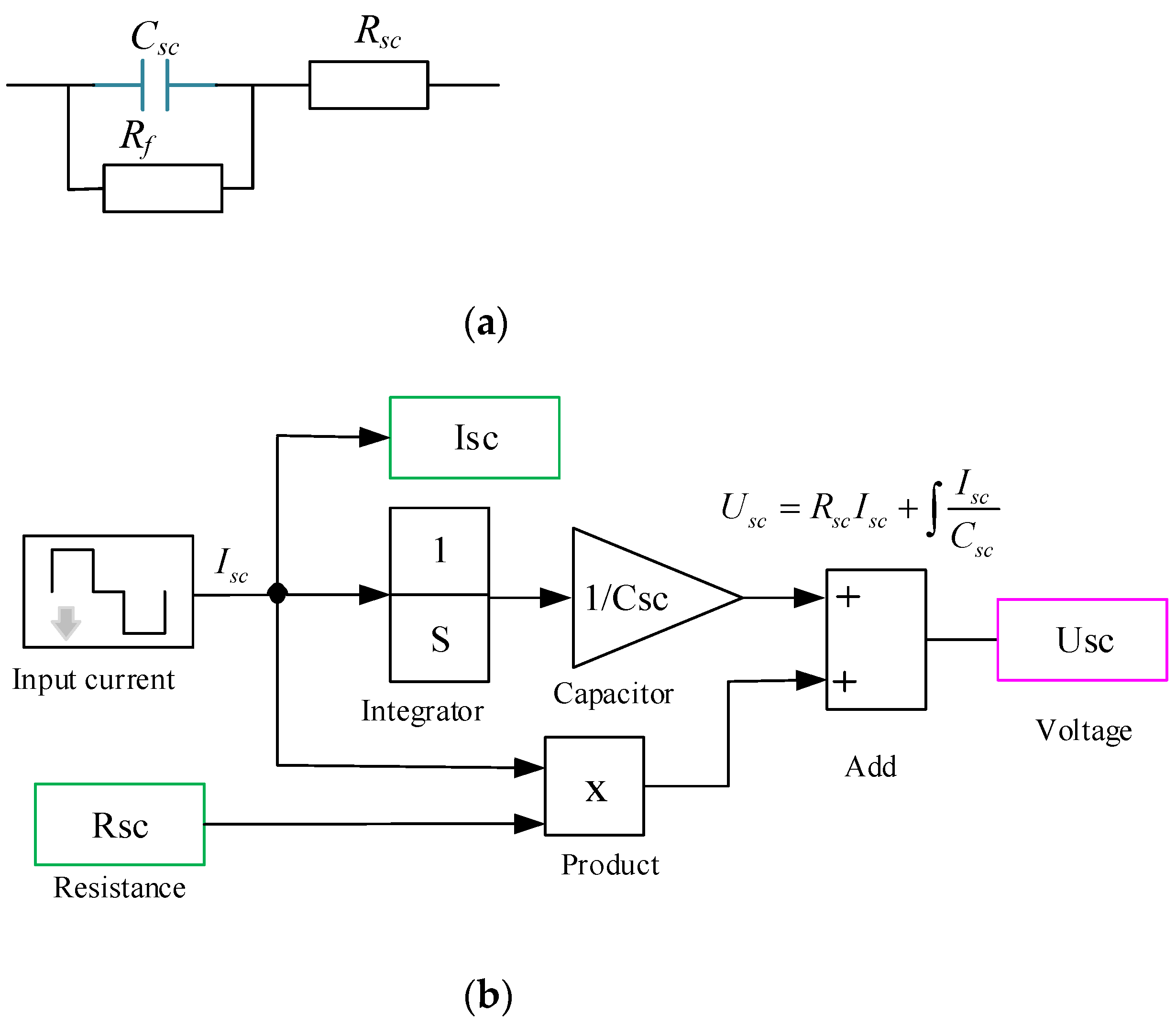
2.1. RC Model of the Supercapacitor

An SC can be schematized by a series resistance Rsc, a leakage resistance Rf and a storage capacitor Csc, as illustrated in Figure 1a, where Rf describes the behaviour of the component during the self-discharge [30].
This basic representation is important. It provides a first idea about SCs. Calculating the equivalent resistance and capacity at a simple discharge test with a constant current is possible. The difference in voltage level between the end of the discharge phase is five seconds and represents the image of the series resistance. The image of the storage capacity is provided by the voltage drop between the initial state (state of rest before discharge) and the final state (five seconds after the discharge).
The modelling of the RC model of the SC in the MATLAB/Simulink environment is shown in Figure 1b by neglecting the leakage current.

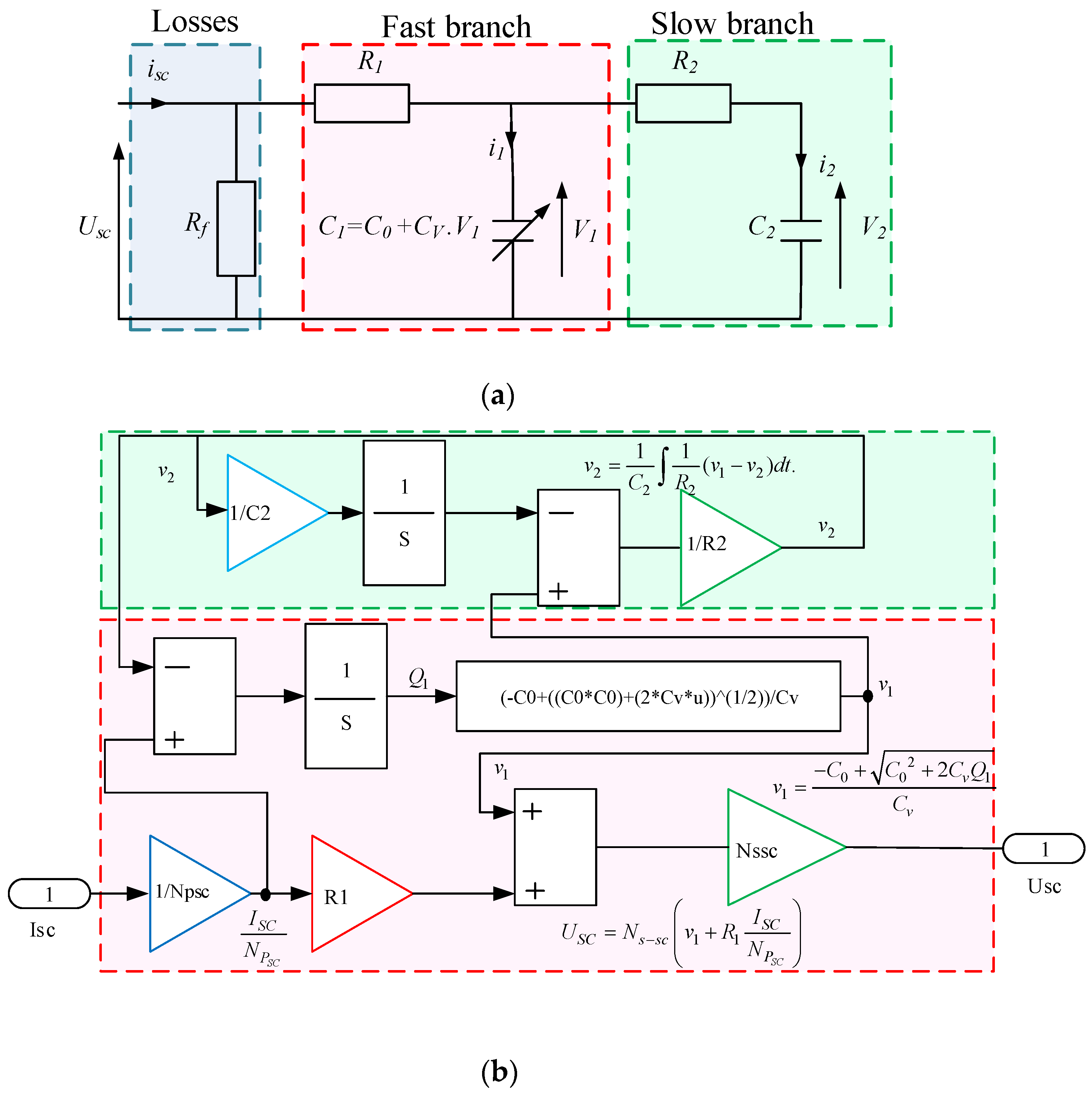
2.2. Two-Branch Model of SCs

The RC two-branch model is used to describe the behaviour of the system by decomposing the response of the last into several parts. Every part is represented a different constant time.
This model, developed by the Canadians Bonert and Zubieta, is composed of:
-
A leakage resistance;
-
Two branches in which capacity is not linear and the voltage is different (Figure 2a) [31,32].
Zubieta and Bonert used this idea to model the SC. They decomposed the response of a SC into two cells:
-
The first cell is the fast branch, which takes into account the charging phases instead of a propagation system. It models this phase by a resistance R1 and a non-linear capacitance C1 (no phenomenon of propagation of charges).
The main capacitance C1 is composed of a constant capacitance C0 and a constant parameter Cv. This capacity is given in terms of the voltage between its terminals v1 by the following equation:
C 1 = C 0 + C v . v 1 .
where v1 is the voltage of C1.
-
The second cell is the slow branch that represents the redistribution phase of the charges during the rest phase. This phase is modelled by an R2C2 branch with larger time constants than those taken for the fast phase.
The leakage resistance Rf symbolizes the self-discharge of the SC, which takes place after the charge redistribution phase.
By neglecting the leakage current, the voltage across the SC can be described by the following equation [22,23,24,25,26,27,28,29,30,31,32]:
U S C = N s s c v s c = N s s c ( v 1 + R 1 I S C N P S C )
where USC and ISC are the voltage and current of the SCs, respectively. Ns−sc and Np−sc are the number of parallel and serial connections of the SCs, respectively. The voltage v2 is given by:
v 2 = 1 C 2 i 2 d t = 1 C 2 1 R 2 ( v 1 v 2 ) d t .
Current i1 is expressed in terms of instantaneous charge Q1 and C1 as follows:
i 1 = C 1 d v 1 d t = d Q 1 d t = ( C 0 + C v . v 1 ) d v 1 d t
where the charge Q1 is given by:
Q 1 = C 0 . v 1 + 1 2 C v . v 1 2
The voltage v1 is defined as follows:
v 1 = C 0 + C 0 2 + 2 C v Q 1 C v
The modelling of the two-branch model of SC in the MATLAB/Simulink environment is shown in Figure 2b.

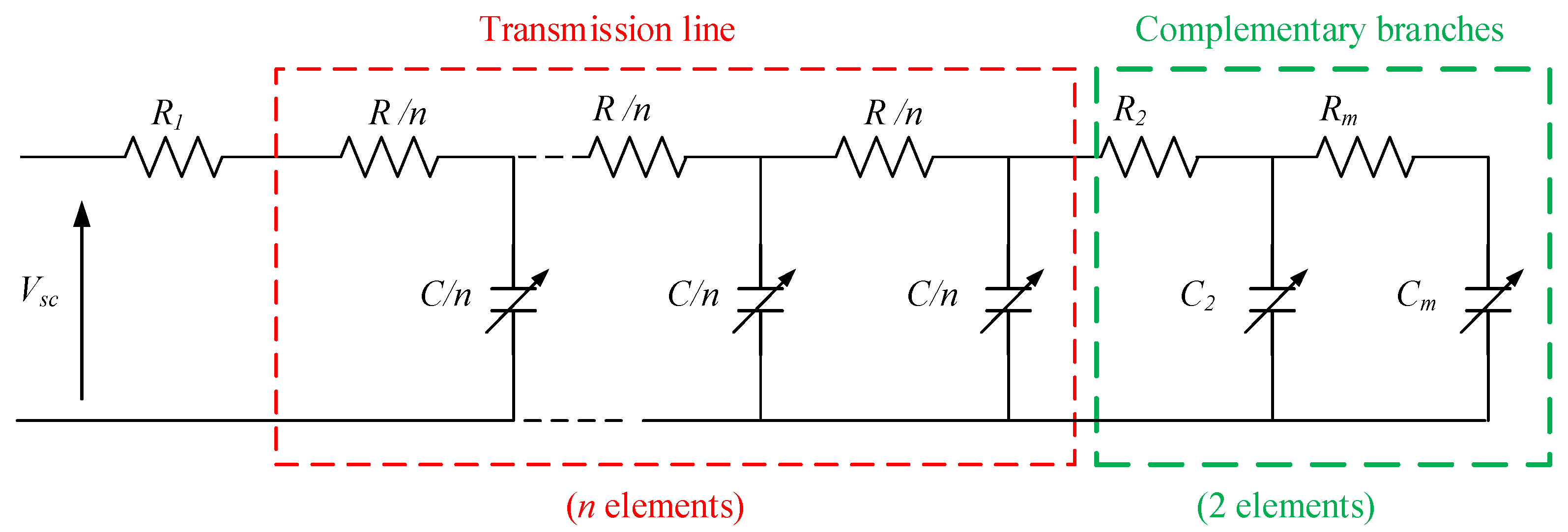
2.3. Multi-Branch Model of SC

The multi-branch model shown in Figure 3 complements the previous two-branch model, including the charge propagation phenomena appearing on the component voltage just after the sudden changes in current. This method uses a simplified model of the transmission line to represent the propagation of charges during the transient (fast phase) and attempts to better take into account the slow behaviour of SCs [32,33,34,35,36].
This model consists of the following:
-
An access resistor R1 for to the transmission line;
-
A non-linear transmission line of n branches in parallel, a total resistance R and a total capacitance C for a fine description of the electrical and energetic behaviours of SCs in short times;
-
Some RC cells to apprehend the longer times.
-
Complementary branches with capacitances Cm and resistances Rm, which will be identified by means of a constant-current partial-charge test, and phases of internal redistribution of energy.
The capabilities of this model vary depending on the voltage at these terminals. The nonlinear capacity model represented in MATLAB/Simulink is depicted in Figure 4.

3. Comparison of the Different Models of the SC

The purpose of this section is to validate the modelling of the different models (RC constructor, two-branch and multi-branch models) by comparing the results obtained by these models to those obtained experimentally by [36]. The SC type used in these simulation tests was the 2700 F Maxwell PC7223.

3.1. Parameters of Different Models

  • RC model of the constructor:
The characteristics given by the constructor are:
The total capacity is Csc = 2700 F;
The total resistance is Rsc = 0.85 mΩ;
The leakage current is Rf = 0 Ω.
  • Parameters of the two-branch model
The extraction of the two-branch model parameters for the Maxwell PC7223 SC, based on the fully charged test with a constant current at 100 A, produced the parameters shown in Table 1.
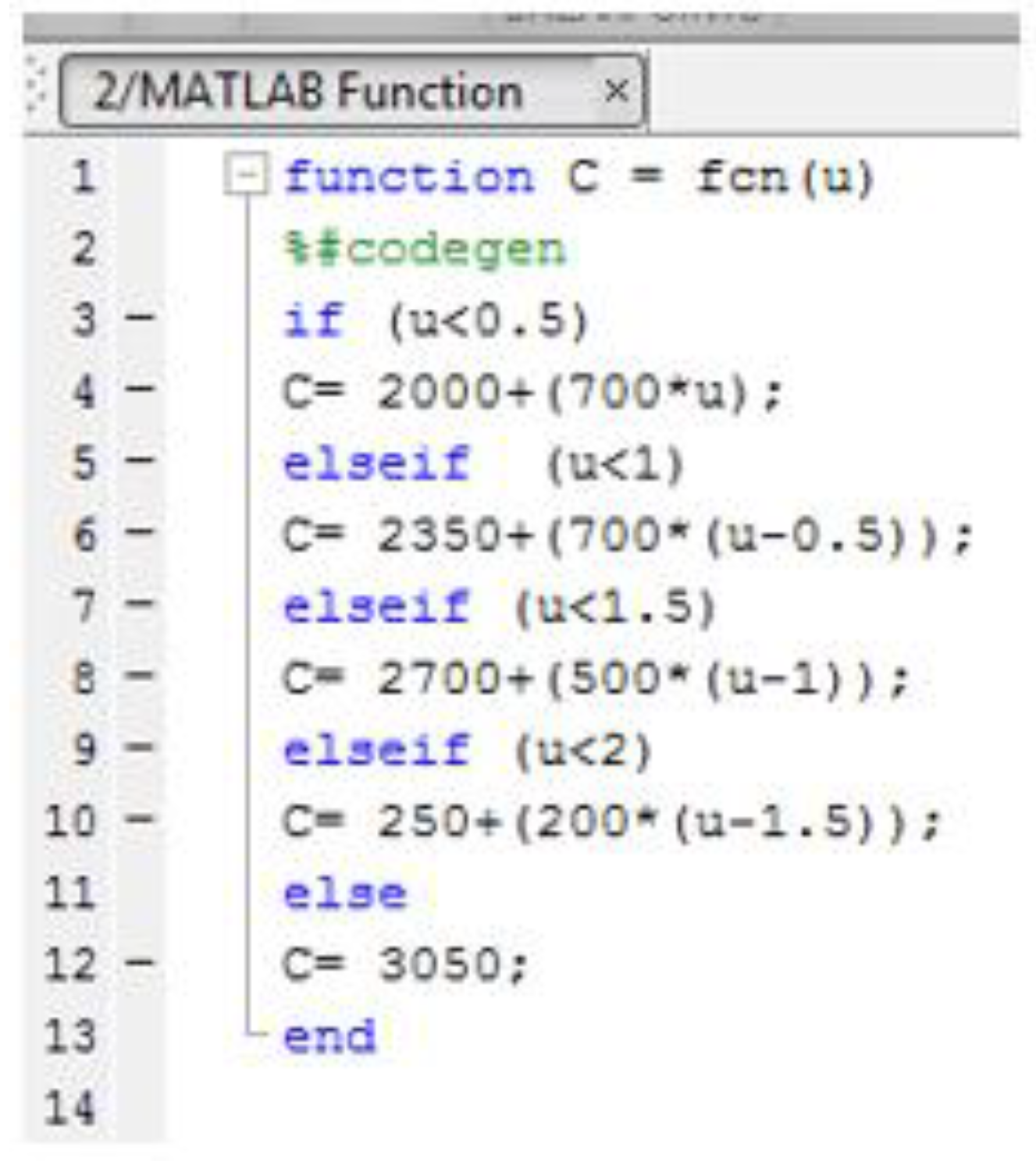
  • Parameters of the multi-branch model
Fifteen branches (n = 15) were proposed for the simulation of the multi-branch model. The identification parameters of a PC7223 SC are given in Table 2. The MATLAB function program is shown in Figure 5.
  • Parameters of the Belhachemi experimental model
Table 3 shows the parameters measured several times by Belhachemi [36].
where:
-
The access resistance is R1 = 0.5 mΩ;
-
The total resistance R = 1.4 mΩ;
-
The resistance of the first complementary branch R2 = 100 mΩ;
-
The resistance of the second complementary branch R3 = 100 mΩ.

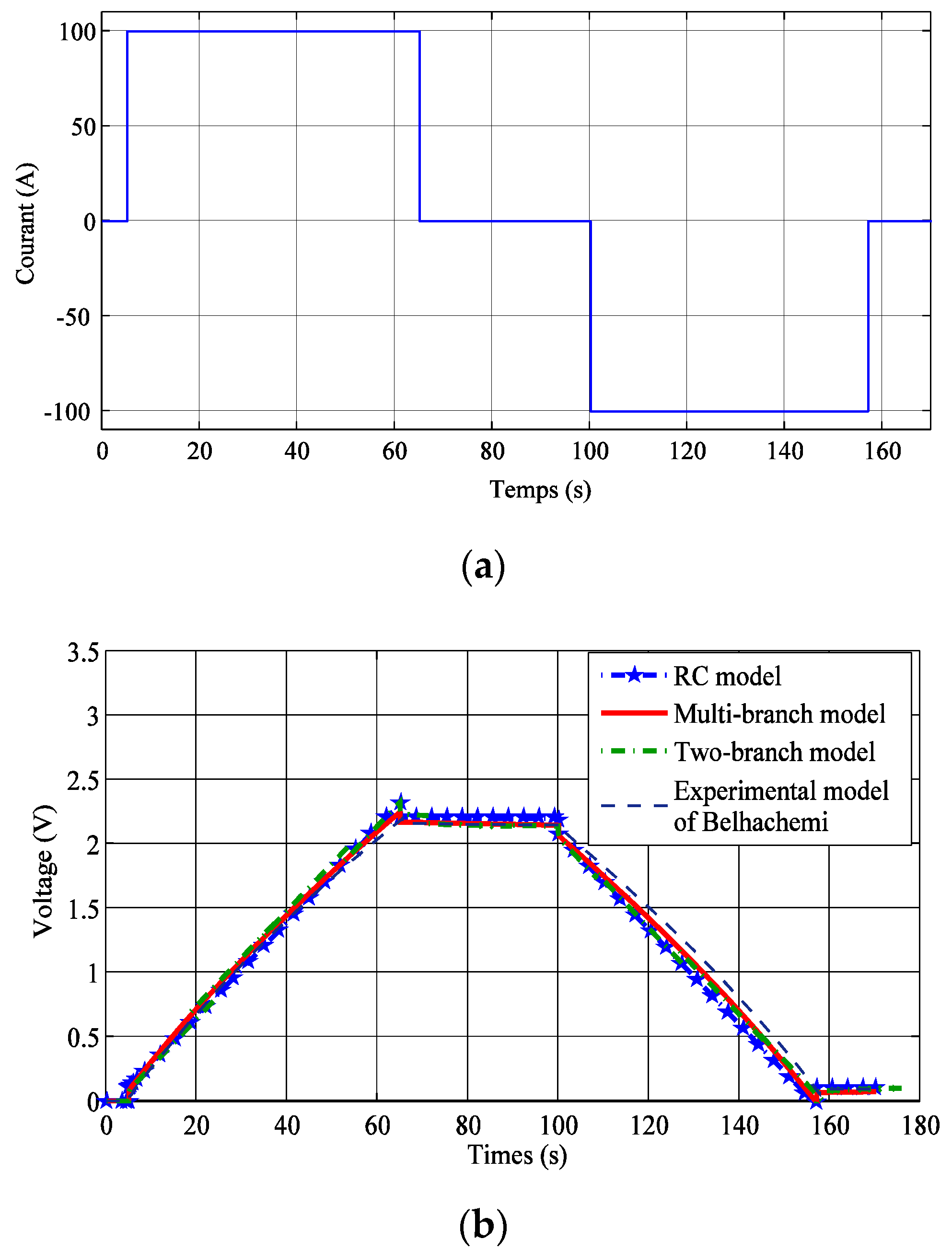
3.2. Simulation and Validation of the Different Models of the SC

A simulation test with a constant current, 100 A for the charge and −100 A for the discharge were proposed to compare the different models. This comparison is shown in Figure 6. The obtained results indicated that the response voltage of the multi-branch model correctly describes the behaviour of the experimental model of Belhachemi. When we increase the number of branches, the precision increases. Fifteen branches is not a fixed number. The simulation time of this model in MATLAB/Simulink was approximately half that the multi-branch model.

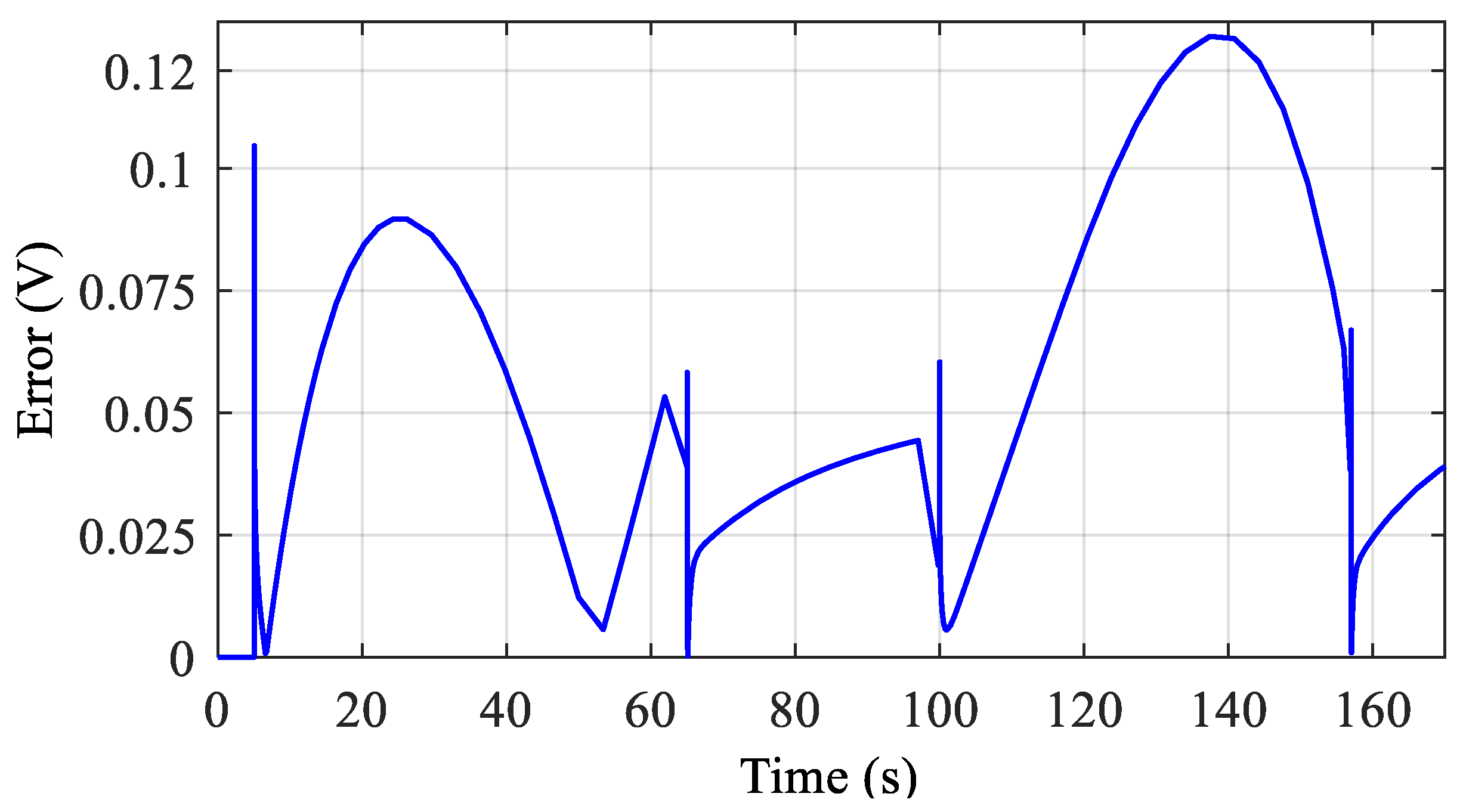
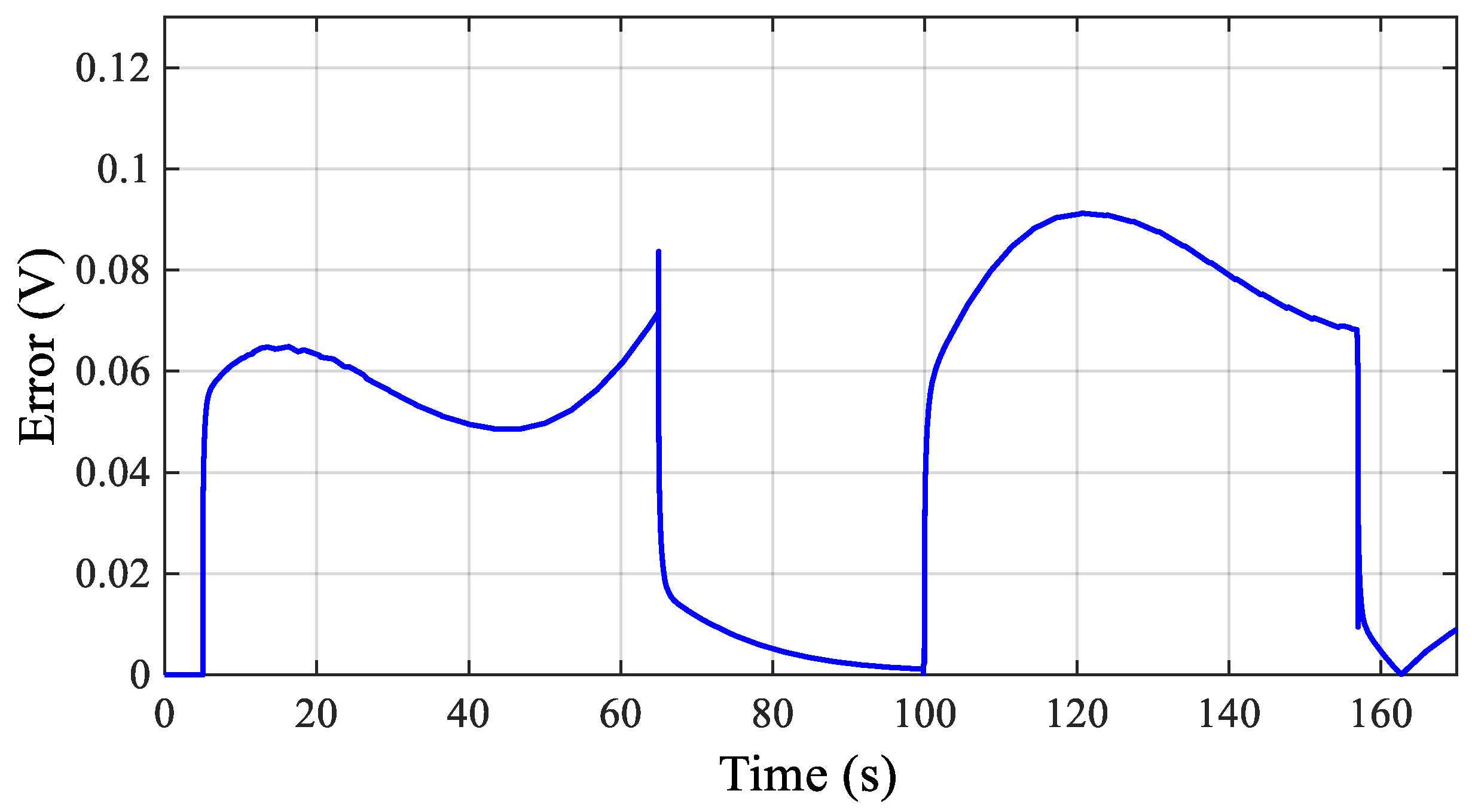
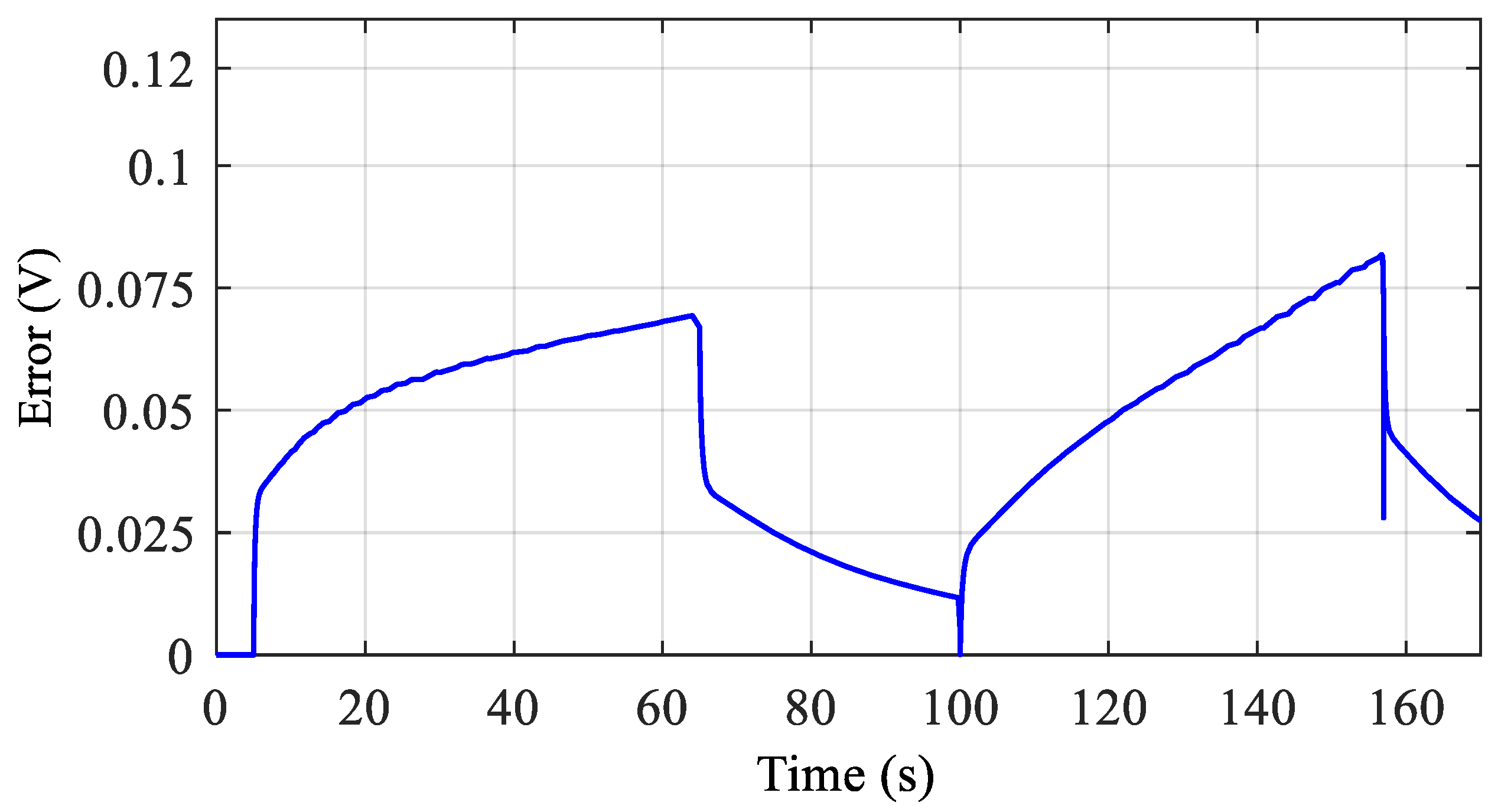
3.3. Calculation of the Error between Different Models of the SC

The difference in errors between the experimental model and the RC, two-branch and multi-branch models is given by Figure 7, Figure 8 and Figure 9, respectively. The RC model represents the very high error of 0.125 V. The two-branch model represents a medium error of 0.09 V. The multi-branch model represents the low error of 0.08 V. The jumps at t = 5, t = 65, t = 100 and t = 155 of voltage are caused by the sudden change of current represented in Figure 6a.

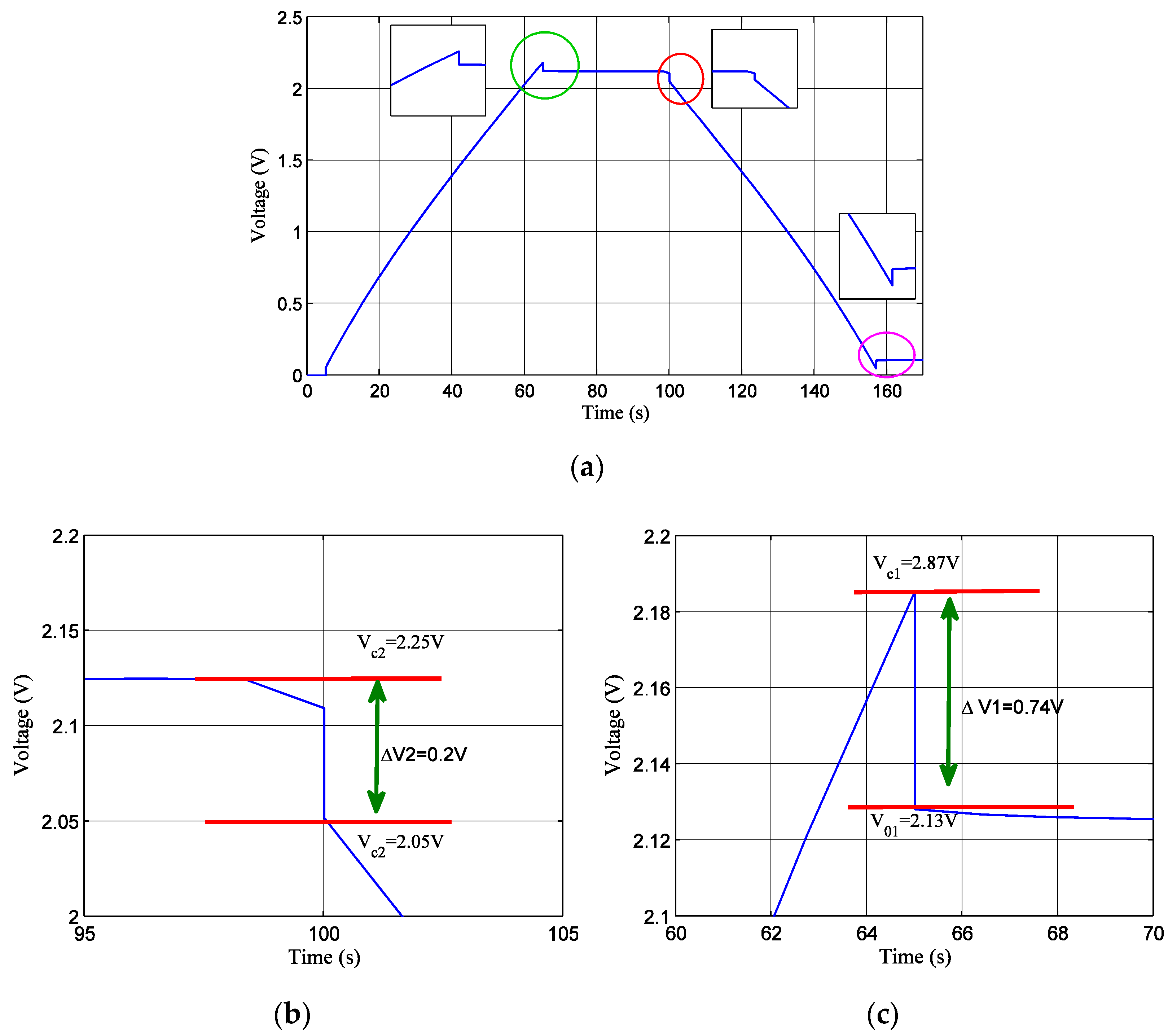
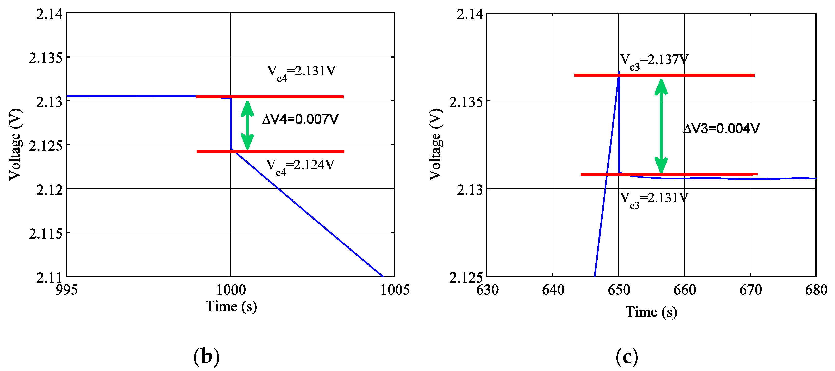
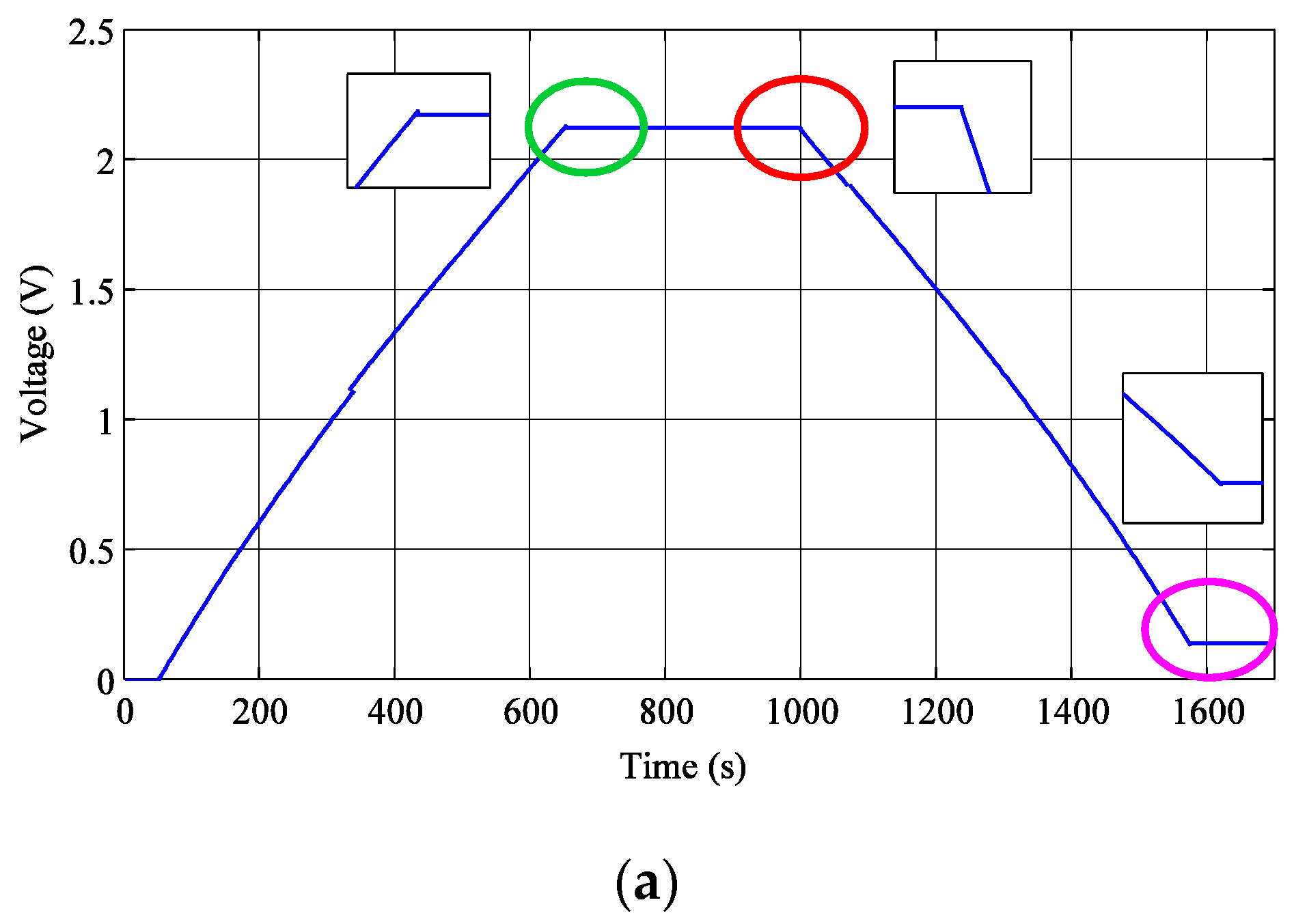
3.4. Influence of the Charge Current on the Voltage

The charge and discharge of the SC with a current of 100 A and 10 A is given in Figure 10 and Figure 11, respectively. With the discharge current of 100 A, the automatic discharge and charge have an important value at t = 65 s, t = 100 s and t = 155 s. The charge and discharge of an SC with a current of 10 A represent a very low automatic charge and discharge. The automatic charge and discharge voltage reduce by reducing the current.

4. Conclusions

The modelling of the RC, two-branch and multi-branch model of SCs are presented in this paper and compared with the experimental model of Belhachemi. This comparison demonstrates that the response voltage of the multi-branch model correctly describes the behaviour of the experimental model. the multi-branch model represents the best accuracy model and gives more precision. The disadvantage of this model is the slow simulation duration in MATLAB/Simulink. The RC model represented the faster model in terms of simulation. The choice of 15 branches in parallel in the multi-branch model gives good results and correctly describes the reel model. The automatic charge and discharge voltage of the SCs reduce by reducing the current.
This paper also presents the modelling of SCs in a MATLAB/Simulink environment of these models.

Author Contributions

Conceptualization, methodology, software, validation, formal analysis, investigation, writing—original draft preparation Z.C.; writing—review and editing, S.H.L. All authors have read and agreed to the published version of the manuscript.

Funding

The results were supported by the “Regional Innovation Strategy (RIS)” through the National Research Foundation of Korea (NRF), funded by the Ministry of Education (MOE) (2021RIS-002) and in part by the Korea Institute of Energy Technology Evaluation and Planning (KETEP) grant funded by the Korean government (MOTIE) 20192010107050, Development of DC power Trade platform system in public community which is connected by EV-renewable based on block chain technology).

Institutional Review Board Statement

Not applicable.

Informed Consent Statement

Not applicable.

Acknowledgments

The results were supported by the “Regional Innovation Strategy (RIS)” through the National Research Foundation of Korea (NRF), funded by the Ministry of Education (MOE) (2021RIS-002) and in part by the Korea Institute of Energy Technology Evaluation and Planning (KETEP) grant funded by the Korean government (MOTIE) (20192010107050, Development of DC power Trade platform system in public community which is connected by EV-renewable based on block chain technology).

Conflicts of Interest

The authors declare no conflict of interest.

References

  1. Liu, X.; Zhao, J.; Cao, Y.; Li, W.; Sun, Y.; Lu, J.; Men, Y.; Hu, J. Facile synthesis of 3D flower-like porous NiO architectures with an excellent capacitance performance. RSC Adv. 2015, 5, 47506–47510. [Google Scholar] [CrossRef]
  2. Nana, H.; Hu, X.; Tian, H. Recent advances in perovskite oxides for anion-intercalation supercapacitor. Mater. Sci. Semicond. Processing 2019, 94, 35–50. [Google Scholar] [CrossRef]
  3. Sharma, K.; Arora, A.; Tripathi, S.K. Review of supercapacitors: Materials and devices. J. Energy Storage 2019, 21, 801–825. [Google Scholar]
  4. Fares, A.M.; Kippke, M.; Rashed, M.; Klumpner, C.; Bozhko, S. Development of a Smart Supercapacitor Energy Storage System for Aircraft Electric Power Systems. Energies 2021, 14, 8056. [Google Scholar] [CrossRef]
  5. Barić, T.; Glavaš, H.; Barukčić, M. Impact of balance resistor uncertainty on voltages across supercapacitors. J. Energy Storage 2019, 22, 131–136. [Google Scholar] [CrossRef]
  6. Beguin, F.; Frackowiak, E.; Lu, M. Supercapacitors: Materials, Systems, and Applications, 1st ed.; Wiley: Hoboken, NJ, USA, 2013. [Google Scholar]
  7. Yu, A.; Chabot, V.; Zhang, J. Electrochemical Supercapacitors for Energy Storage and Delivery: Fundamentals and Applications (Electrochemical Energy Storage and Conversion), 1st ed.; CRC Press: Boca Raton, FL, USA, 2013. [Google Scholar]
  8. Miller, J.M. Ultracapacitor Applications; The Institution of Engineering and Technology: London, UK, 2011. [Google Scholar]
  9. Conway, B.E. Electrochemical Supercapacitors; Kluwer Academic/Plenum Publishers: New York, NY, USA, 1999. [Google Scholar]
  10. Cheng, X.; Zhang, D.; Liu, X.; Cao, D.; Wang, G. Influence of CTAB on morphology, structure, and supercapacitance of β-Ni (OH)2. Ionics 2015, 12, 533–540. [Google Scholar] [CrossRef]
  11. Cabrane, Z.; Ouassaid, M.; Maaroufi, M. Battery and Supercapacitor for Photovoltaic Energy Storage: A Fuzzy Logic Management. IET Renew. Power Gener. (RPG) J. 2017, 11, 1157–1165. [Google Scholar] [CrossRef]
  12. Logerais, P.O.; Camara, M.A.; Riou, O.; Djellad, A.; Omeiri, A.; Delaleux, F.; Durastanti, J.F. Modeling of a supercapacitor with a multibranch circuit. Int. J. Hydrogen Energy 2015, 40, 13725–13736. [Google Scholar] [CrossRef]
  13. Ayad, M.Y.; Becherif, M.; Henni, A. Vehicle hybridization with fuel cell, supercapacitors and batteries. Renew. Energy 2011, 36, 2627. [Google Scholar] [CrossRef]
  14. Marie-Francoise, J.N.; Gualous, H.; Outbib, R.; Berthon, A. 42V power net with supercapacitor and battery for automotive applications. J. Power Sources 2005, 143, 275. [Google Scholar] [CrossRef]
  15. Zhou, H.; Bhattacharya, T.; Tran, D.; Siew, T.S.T.; Khambadkone, A.M. Composite energy storage system involving battery and ultracapacitor with dynamic energy management in microgrid applications. IEEE Trans. Power Electron 2011, 3, 923–930. [Google Scholar] [CrossRef]
  16. Yang, H. A Review of Supercapacitor-Based Energy Storage Systems for Microgrid Applications. In Proceedings of the 2018 IEEE Power and Energy Society General Meeting (PESGM 2018), Portland, OR, USA, 5–9 August 2018; pp. 1–5. [Google Scholar]
  17. Yoo, H.; Sul, S.; Park, Y.; Jeong, J. System integration and power-flow management for a series hybrid electric vehicle using supercapacitors and batteries. IEEE Trans. Ind. Appl. 2008, 44, 108–114. [Google Scholar] [CrossRef]
  18. Herrera, V.I.; Gaztanaga, H.; Milo, A.; Ibarra, A.S.; Etxeberria-Otadui, I.; Nieva, T. Optimal energy management and sizing of a battery-supercapacitor-based light rail vehicle with a multiobjective approach. IEEE Trans. Ind. Appl. 2016, 52, 3367–3377. [Google Scholar] [CrossRef]
  19. Kouchachvili, L.; Yaici, W.; Entchev, E. Hybrid battery/supercapacitor energy storage system for the electric vehicles. J. Power Sources 2018, 374, 237–248. [Google Scholar] [CrossRef]
  20. Cabrane, Z.; Ouassaid, M.; Maaroufi, M. Performance Enhancement of Solar Vehicle by Integration of Supercapacitors in the Energy Storage System. In Proceedings of the 2014 International Renewable and Sustainable Energy Conference, Ouarzazate, Morocco, 17–19 October 2014. [Google Scholar]
  21. Cabrane, Z.; Batool, D.; Kim, J.H.; Yoo, K. Design and simulation studies of battery-supercapacitor hybrid energy storage system for improved performances of traction system of solar vehicle. J. Energy Storage 2020, 32, 101943. [Google Scholar] [CrossRef]
  22. Lahyani, A.; Venet, P.; Guermazi, A.; Troudi, A. Battery/supercapacitors combination in uninterruptible power supply (UPS). IEEE Trans. Power Electron 2013, 28, 1509–1522. [Google Scholar] [CrossRef]
  23. Cabrane, Z.; Kim, J.H.; Yoo, K.; Ouassaid, M. HESS-based photovoltaic/batteries/supercapacitors: Energy management strategy and DC bus voltage stabilization. Sol. Energy 2021, 216, 551–563. [Google Scholar] [CrossRef]
  24. Yang, H.; Zhang, Y. A task scheduling algorithm based on supercapacitor charge redistribution and energy harvesting for wireless sensor nodes. J. Energy Storage 2016, 6, 186–194. [Google Scholar] [CrossRef]
  25. Yang, H.; Zhang, Y. Power Management in Supercapacitor-Based Wireless Sensor Nodes, Supercapacitor Design and Applications; InTech: London, UK, 2016; pp. 165–179. [Google Scholar]
  26. Long, Q.; Celna, A.; Das, K.; Sørensen, P. Fast Frequency Support from Hybrid Wind Power Plants Using Supercapacitors. Energies 2021, 14, 3495. [Google Scholar] [CrossRef]
  27. Bose, S.; Kuila, T.; Mishra, A.K.; Rajasekar, R.; Kim, N.H.; Lee, J.H. Carbon-based nanostructured materials and their composites as supercapacitor electrodes. J. Mater. Chem. 2012, 3, 767–784. [Google Scholar] [CrossRef]
  28. Snook, G.A.; Kao, P.; Best, A.S. Conducting-polymer-based supercapacitor devices and electrodes. J. Power Sources 2011, 196, 1–12. [Google Scholar] [CrossRef]
  29. Yuan, C.; Yang, L.; Hou, L.; Shen, L.; Zhang, X.; Lou, X.W. Growth of ultrathin mesoporous Co3O4 nanosheet arrays on Ni foam for high-performance electrochemical capacitors. Energy Environ. Sci. 2012, 5, 7883–7887. [Google Scholar] [CrossRef]
  30. Nelms, R.M.; Cahela, D.R.; Tatarchuk, B.J. Modeling double-layer capacitor behavior using ladder circuits. IEEE Trans. Aerosp. Electron. Syst. 2003, 39, 430–438. [Google Scholar] [CrossRef]
  31. Lahyani, A.; Sari, A.; Lahbib, I.; Venet, P. Optimal hybridization and amortized cost study of battery/supercapacitors system under pulsed loads. J. Energy Storage 2016, 6, 222–231. [Google Scholar] [CrossRef]
  32. Negroiu, R.; Svasta, P.; Vasile, A.; Ionescu, C.; Marghescu, C. Comparison between Zubieta model of supercapacitors and their real behavior. In Proceedings of the 2016 IEEE 22nd International Symposium for Design and Technology in Electronic Packaging, SIITME 2016, Oradea, Romania, 20–23 October 2016; pp. 196–199. [Google Scholar]
  33. Lai, J.S.; Levy, S.; Rose, M.F. High energy density double-layer capacitors for energy storage applications. IEEE Aerosp. Electron. Syst. Mag. 1992, 7, 14–19. [Google Scholar] [CrossRef]
  34. Zhao, Y.; Xie, W.; Fang, Z.; Liu, S. A Parameters Identification Method of the Equivalent Circuit Model of the Supercapacitor Cell Module Based on Segmentation Optimization. IEEE Access 2020, 8, 92895–92906. [Google Scholar] [CrossRef]
  35. Cabrane, Z.; Ouassaid, M.; Maaroufi, M. Integration of supercapacitor in photovoltaic energy storage: Modelling and control. In Proceedings of the 2014 International Renewable and Sustainable Energy Conference, Ouarzazate, Morocco, 17–19 October 2014. [Google Scholar]
  36. Belachemi, F. Modeling and Characterization of Electric Double-Layer Supercapacitors Used in Power Electronic. Thesis, Electrical Engineering, L’Institut National Polytechnique de Lorraine, France, 2000. [Google Scholar]
Figure 1. (a) RC model of the SC. (b) RC model of SC under MATLAB/Simulink by negleging Rf.
Energies 15 00693 g001
Figure 2. (a) SC model with two branches [31]. (b) Representation of the two-branch RC model in MATLAB/Simulink.
Energies 15 00693 g002
Figure 3. Multi-branch model of the SC.
Energies 15 00693 g003
Figure 4. Composition of the block of the variable capacity.
Energies 15 00693 g004
Figure 5. MATLAB function program.
Energies 15 00693 g005
Figure 6. Comparison of the voltage of the different models of the SC type Maxwell PC7223: (a) SC current; (b) SC voltage.
Energies 15 00693 g006
Figure 7. Error between experimental and RC models.
Energies 15 00693 g007
Figure 8. Error between experimental and two-branch models.
Energies 15 00693 g008
Figure 9. Error between experimental and multi-branch models.
Energies 15 00693 g009
Figure 10. Charge and discharge of SC with a current of 100 A: (a) Charge and discharge curve of SC with a current of 100 A. (b) Self-discharge of SC with a current of 100 A after full charge. (c) Self-discharge of SC with a current of 100 A before charging.
Energies 15 00693 g010
Figure 11. Charge and discharge of SC with a current of 10 A: (a) Charge and discharge curve of SC with a current of 10 A. (b) Self-discharge of SC with a current of 10 A in the start of discharging. (c) Self-discharge of SC with a current of 10 A in the end of discharging.
Energies 15 00693 g011aEnergies 15 00693 g011b
Table 1. Parameters of the two-branch model of the SC.
ParametersValues
R10.8 mΩ
C02170 F
Cv520 F/V
R21 Ω
C2150 F
Table 2. Identified parameters of the multi-branch model of SC PC7223 [35].
Voltage (V)Transmission Line
R = 1.1 mΩ
Branch R2C2
R2 = 100 mΩ
Branch R3C3
R3 = 1 Ω
Capacity C (F)Capacity C2 (F)Capacity C3 (F)
0 V, 0.5 VC = 2000 + 700 vC2 = 90 + 30 vC3 = 31 + 11 v
0.5 V, 1 VC = 2350 + 700 (v − 0.5)C2 = 105 + 30 (v − 0.5)C3 = 36.5 + 30 (v − 0.5)
1 V, 1.5 VC = 2700 + 500 (v − 1)C2 = 120 + 22 (v − 1)C3 = 42 + 8 (v − 1)
1.5 V, 2 VC = 2950 + 200 (v − 1.5)C2 = 131 + 5 (v − 1.5)C3 = 46 + 3 (v − 1.5)
v > 2 VC = 3050C2 = 133.5C3 = 51
Table 3. Parameters of supercapacitor Maxwell PC 7223 [36].
Voltage (in V)The Capacity of the Transmission LineFirst Complementary BranchSecond Complementary Branch
020009031
0.5235010536.5
1270012042
1.5295013146
23050133.551
2.53050133.551
Publisher’s Note: MDPI stays neutral with regard to jurisdictional claims in published maps and institutional affiliations.

