Article

The Influence of Particle Size and Hydrate Formation Path on the Geomechanical Behavior of Hydrate Bearing Sands

by
Mandeep R. Pandey
*,
Jeffrey A. Priest
and
Jocelyn L. Hayley
Department of Civil Engineering, University of Calgary, Calgary, AB T2N 1N4, Canada
*
Author to whom correspondence should be addressed.
Energies 2022, 15(24), 9632; https://doi.org/10.3390/en15249632
Submission received: 18 November 2022 / Revised: 12 December 2022 / Accepted: 15 December 2022 / Published: 19 December 2022
(This article belongs to the Special Issue Gas Hydrate Energy Technologies for Net-Zero Carbon Emissions)

Abstract

:
Determining the geomechanical properties of hydrate-bearing sands (HBS), such as strength and stiffness, are critical for evaluating the potential for the economic and safe recovery of methane gas from HBS reservoirs. To date, results from numerous independent laboratory studies on synthesized HBS have shown that strength and stiffness are largely influenced by hydrate saturation, the method adopted for hydrate formation, and to a lesser extent, the confining stresses applied during testing. However, a significant scatter is observed in the data even when these conditions are similar. These include recent studies on natural HBS where sands with larger particle size distribution (PSD) exhibited higher strengths despite lower hydrate saturation. To investigate the impact of PSD, and the role that specific hydrate formation conditions might impose, on the strength and stiffness of HBS, a series of laboratory tests were carried out on sand specimens formed with different particle size distributions and utilizing different approaches for forming gas saturated HBS. The laboratory apparatus included a resonant column drive head to measure the small-strain stiffness of the specimen during hydrate formation, and subsequent drained compressional shearing to capture the stress-strain response of the HBS. Results indicate that the PSD significantly affects both the stiffness evolution (during hydrate formation) and peak strength at failure after formation compared to the effect of the methodology adopted for hydrate formation. These observations improve our understanding of the geomechanical behavior of laboratory-synthesized HBS and allow more robust relationships to be developed between them and natural HBS. This may aid in the development of economic and safe methane gas production methods to help realize the energy resource potential of HBS reservoirs.

1. Introduction

Methane gas hydrate is an ice-like crystalline compound, where methane gas molecules are encaged in a lattice of water molecules. Hydrates naturally form under high pressure and low temperature conditions within sediments on continental margins, and under the permafrost, when sufficient methane gas is freely available [1,2,3,4]. Methane hydrates are of interest as a possible energy resource owing to the enormous volumes of methane gas that is sequestered in the hydrate within these sediments [5]. A significant proportion of this hydrate resides within fine-grained soils. However, the relative low hydrate saturation of the pore space, the low permeability of the sediment, and challenges associated with the unconsolidated nature of fine-grained soils suggest that these are not commercially exploitable [6]. On the other hand, methane hydrate saturation in the pore space of coarse-grained sediments can reach up to 90% [7,8], and along with the high intrinsic permeability of the sands, these sediments are of huge interest for energy resource development [3,4,9,10]. Current estimates suggest that up to 3 × 10¹⁴ m3 of methane gas [4] is contained in coarse grained sediments (commensurate with known conventional gas estimates) and may be feasible to produce using current oil and gas technologies [11].
Limited small-scale field tests on permafrost deposits [12,13] and marine sediments [14,15,16,17] have indicated the potential viability of methane production from hydrate deposits. However, the short-term nature of these tests, exacerbated by unforeseen circumstances that have prematurely ended tests [15], has prevented the long-term production potential of hydrate deposits from being explored. Although numerical simulations help in understanding the long-term potential [18,19,20,21,22], these simulations require accurate input parameters, starting from the formation of such deposits, to give realistic predictions. Despite numerous studies on hydrate systems [5,23,24,25,26], the actual process controlling the formation of high saturation hydrate-bearing sands (HBS) is yet to be fully understood.
Testing of intact natural HBS samples is challenging. Therefore, laboratory-synthesized hydrate-bearing soils have been typically used to develop our foundational understanding of HBS, as these can produce hydrate specimens similar in textures, phase distributions, and grain contacts to those found in nature [27]. Studies on laboratory-synthesized HBS have investigated behaviors such as stiffness, stiffness evolution, strength, and deformation during dissociation that would be important considerations for the long-term development of hydrates. However, there are notable differences in the behavior between a limited number of natural HBS tested versus laboratory-synthesized HBS [28]. Laboratory tests until now have typically been performed on artificial porous materials [29,30,31,32] or on sands with a narrow particle size distribution (PSD) [33,34,35,36]. Miyazaki et al. [37] considered different particle sizes in their study and reported strength to be relatively independent of the type of sand, although they reported the dependence of stiffness on the type of sand forming the skeleton. However, they tested relatively narrow PSDs with mean particle size (D50) ranging from 130m to 230m. In contrast, a recent natural HBS core obtained during the 2018 Indian National Gas Hydrate Project (NGHP-02) expedition [38] showed a much wider PSD with larger sand particles >1 mm being present. Furthermore, the results from the limited testing conducted suggested that samples with larger particles significantly influenced the geomechanical properties of the HBS [38].
To investigate further the potential role of PSD on the geomechanical response of a HBS, and the role different hydrate formation methods may have, this paper presents the results from a series of tests conducted on HBS specimens formed with different PSDs and subjected to different methods of hydrate formation. Other test conditions that may impact the geomechanical properties of HBS, such as confining stresses and hydrate saturation, as well as shear strain rate and specimen density, were kept reasonably constant. Specimens were subjected to resonant column testing during hydrate formation to investigate small-strain stiffness, subsequently followed by triaxial shearing to evaluate their stress-strain response. The results were analyzed to gain insight into the impact of hydrate formation methodologies on the stiffness and strength response for two different sand mixtures.

2. Materials and Methods

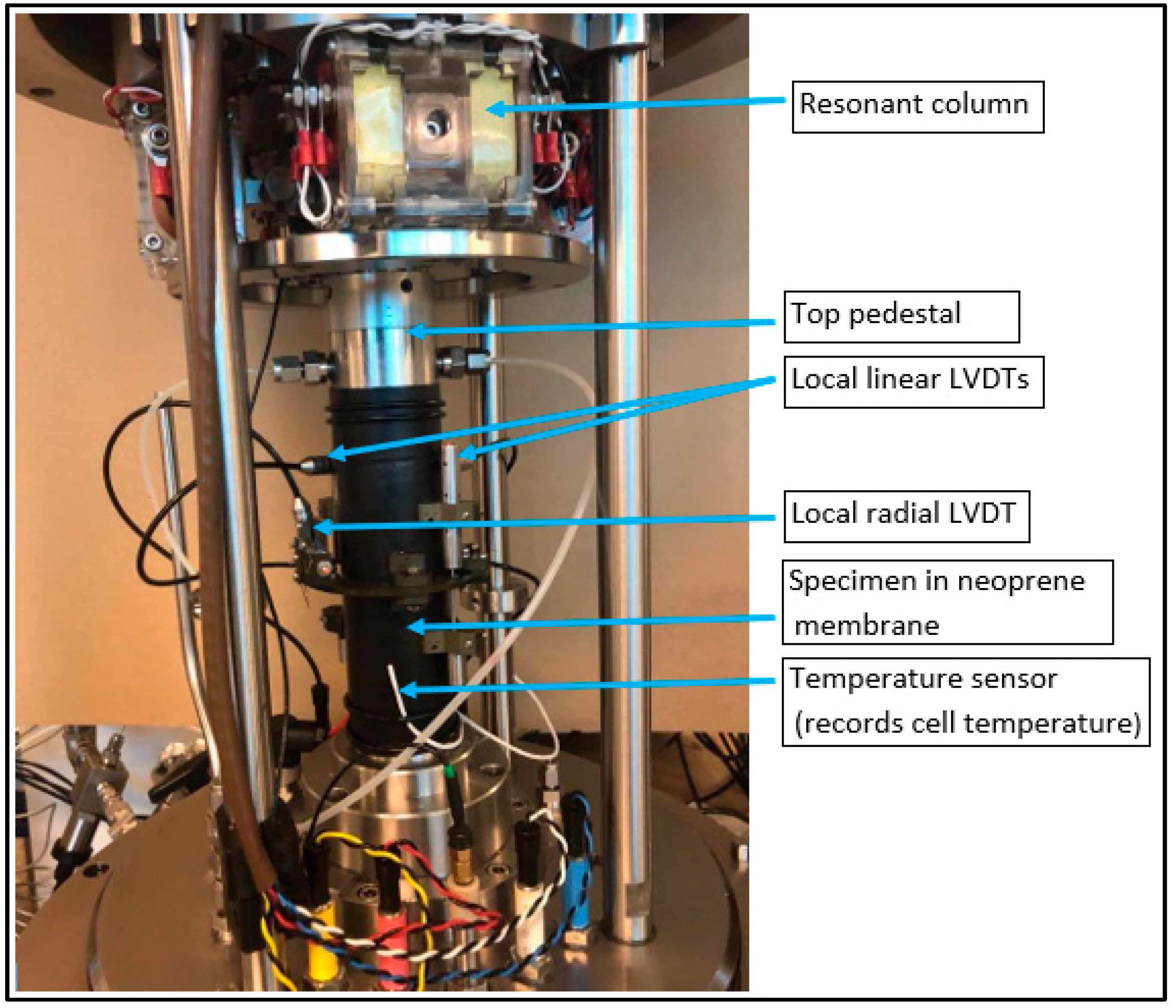
2.1. Experimental Set Up

An Environmental Triaxial Automated System (ETAS) manufactured by GDS Instruments was used for the laboratory testing of HBS. A schematic of the test apparatus and various components are presented in Figure 1. The ETAS consists of a Hardin-type resonant column (RC) drive head which applies sinusoidal torsional excitation for small-strain testing, and a triaxial loading system for large-strain tests. The triaxial cell allows specimens to be tested under the maximum confining pressure of 20 MPa. The temperature of the specimen is controlled by circulating glycol through coiled tubes inside the cell which are connected to an external cooling unit that can control specimen temperature from −30 °C to +65 °C and has a temperature resolution of 0.01 °C. An insulated jacket around the cell helps maintain the inside temperature by minimizing heat exchange with the surrounding. Computer-controlled pneumatic gas regulators apply and control nitrogen gas cell pressure to the cell, and methane gas back pressure to the specimen pore space. An advanced pressure-volume controller (PVC) with a maximum pressure rating of 32 MPa controls the back pressure (through the base pedestal) and records the volume of methane gas consumed during hydrate formation. The load applied to the specimen by a 64 kN internal load cell is used to estimate axial stresses during testing. Local linear variable displacement transducers (LVDTs) measure displacements of the specimen. Two temperature sensors, one fixed to the base pedestal and another attached to the outside of the membrane, record the internal temperature of the specimen and cell, respectively, throughout the test.
Two axial LVDTs (0-10 mm range) were attached over the middle third of the specimen on opposite sides, with a radial LVDT (+/− 5 mm range) attached to the mid-height of the specimen. Figure 2 shows a specimen mounted on the base pedestal and with the LVDTs attached. An additional external axial LVDT (0–50 mm), mounted on the cell, was used to measure global axial displacement. From the measured displacements, axial and radial strains were calculated, along with volumetric strains using an assumed sinusoidal deformation profile [39].

2.2. Soil Selection

Two sands with different PSDs were considered in this study, herein named coarse sand (CS) and fine sand (FS), to consider the influence of particle size and their distribution on measured mechanical properties. The particle sizes chosen were based on the observation from field testing during the NGHP-02 expedition [38]. The properties of each sand mix, including the D10, D50, and D90 particle sizes, as well as the minimum and maximum void ratios (emax and emin) are given in Table 1. As the geomechanical properties of specimens are also influenced by density, a void ratio of 0.55 was targeted for all the experiments.
A uniform distribution of water within the pore space of a sand specimen over its length prior to hydrate formation is an important factor for trying to ensure a uniform hydrate distribution [40,41]. Therefore, a series of water retention tests were carried out to evaluate the water distribution within a given sand specimen at a water content (w/c) that corresponds to a target hydrate saturation. Sand specimens were first formed by tamping unsaturated sand (at the target w/c) into a sample mold and then subsequently split into 5 equal layers down the length of the specimen, and the w/c for each layer was determined. It can be seen for the coarse sand that only minor differences in w/c are shown along the length of the specimen (Figure 3a). Measurement of water distribution for a HBS specimen after hydrate formation and subsequent shearing (Figure 3b) show reasonably good agreement with the initial distribution suggesting that negligible fluid migrations occur during hydrate formation in the chosen sands.

2.3. Specimen Preparation

Sand specimens (50 mm diameter and 100 mm height) were formed by hand tamping partially saturated sand in 10 equal layers within a Neoprene membrane secured to the base pedestal and held within a sample mold. Once compacted, the base pedestal and specimen were transferred to the pressure cell with the pedestal fixed to the cell base before the loading ram was brought into contact with the sand specimen to secure the membrane to the top cap. A suction of ~50 kPa was applied to the specimen pore space to allow the removal of the sample mold and measure specimen dimensions. The initial porosity of the specimen was calculated based on the dry mass of sand used and the measured specimen dimension after the application of suction. This calculated porosity and the mass of water in the sand were used to calculate the hydrate saturation. The local LVDTs (including two axial and one radial) were then attached to the specimen (Figure 2). The LVDTs were fixed over the middle third of the specimen since this region is considered unrestrained [42] and constitutes the primary zone of shearing. In addition to the temperature sensor located at the base of the specimen, a further sensor was attached to the membrane on the outside of the specimen to measure and control cell temperature. The pressure cell was then lowered and sealed before filling silicon oil up to the top of the specimen. The cell was then pressurized to 700 kPa cell pressure while simultaneously raising the specimen back pressure to 200 kPa using methane gas. There was no appreciable change in specimen dimension during the increase in effective stress as measured by the LVDTs to hugely impact the porosity.

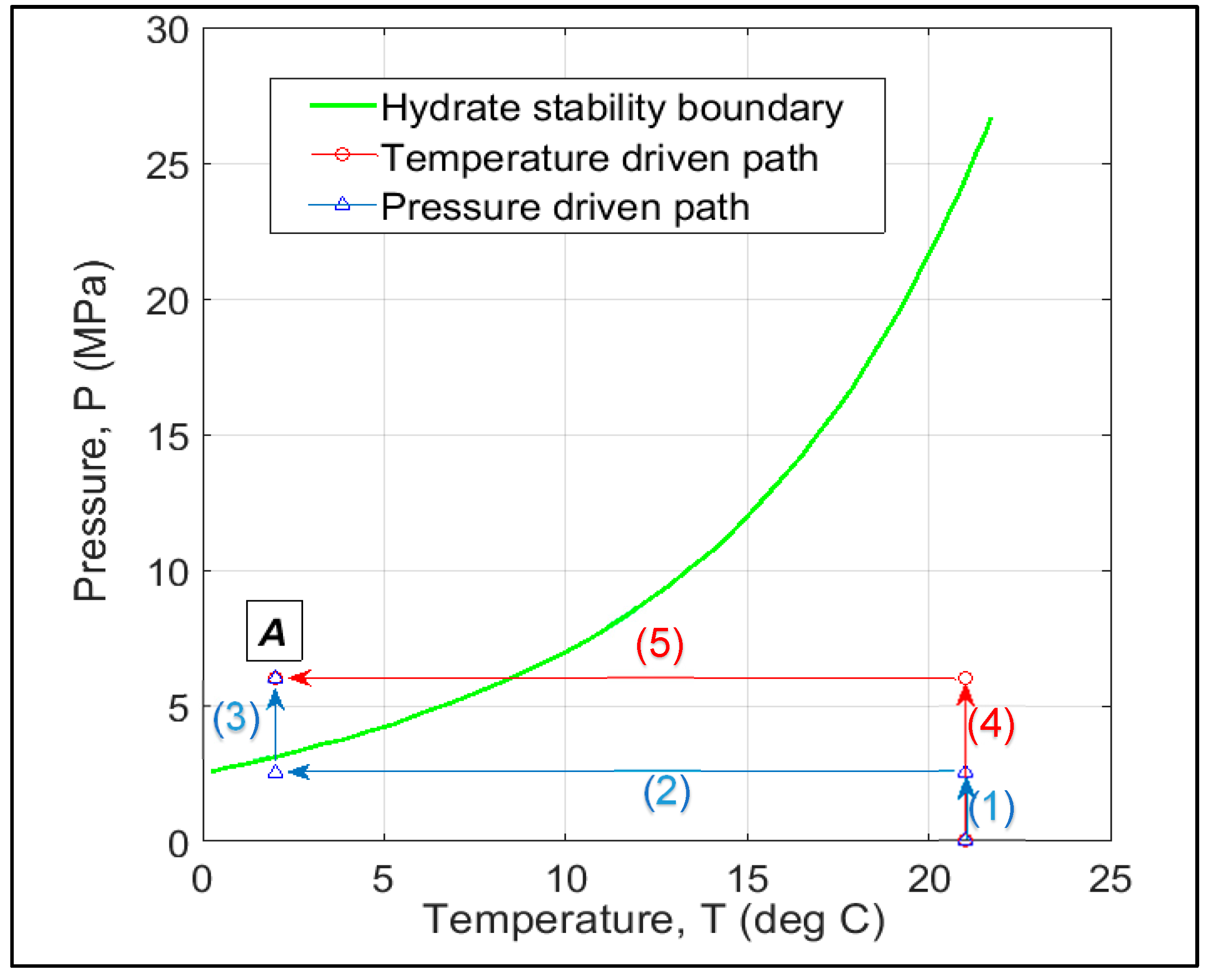
2.4. Hydrate Formation

The process of forming hydrate used in the laboratory can directly influence hydrate morphology which in turn influences the mechanical behavior of HBS. In this study, hydrates were formed using the excess gas method [43] but following two different pressure—temperature (P-T) paths (Figure 4). One P-T path is defined as ‘pressure driven’ where the gas pressure is increased into the hydrate stability region under constant temperature to initiate hydrate formation. This could be considered similar to natural environments where methane gas is generated either in-situ or migrates along permeable pathways, increasing the local pore pressure for a given temperature. The second P-T path is termed ‘temperature driven’ where the methane gas-charged specimens’ temperature is lowered into the hydrate stability region to initiate hydrate formation. This could be similar to the conditions experienced in permafrost regions where propagation of cooler temperatures brought sediments into the hydrate stability region [44]. The main reason for focusing on these two formation paths is that in nature the hydrates are found within deep water marine sediments and below the permafrost [45].
In the pressure-driven formation method, methane gas was initially injected at a rate of 100 kPa/min into the partially saturated sand specimen until the pore pressure reached 2500 kPa while maintaining an effective stress of 500 kPa (path 1 in Figure 4). The temperature of the specimen was then reduced to 2 °C (path 2), which was just outside the hydrate stability zone for the applied pore pressure. After the specimen temperature had stabilized, the methane pore pressure was increased at a rate of 100 kPa/min (path 3) into the hydrate stability region with subsequent initiation of hydrate formation. In this study, all the specimens were tested at a pore pressure of 6000 kPa and a temperature of 2 °C (point A in Figure 4) with an effective stress of 500 kPa. In the temperature-driven formation method, methane gas was initially injected into the pore space of the sand up to 6000 kPa while increasing cell pressure to achieve the target effective stress of 500 kPa (path 4). The temperature of the specimen was then reduced (path 5) to bring the specimen into the hydrate stability region and initiate hydrate formation. For this path, the temperature was first reduced to ~7 °C overnight and then reduced to 2 °C during the working day to allow RC testing throughout the hydrate formation stage, and ensure that the initial hydrate formation and resulting stiffness evolution were captured.
Hydrate saturation was calculated using Equation (1) assuming all the water was converted to hydrate at a molar ratio of methane to water of 1:5.75 [46] at the end of the formation process.
S h = m w × M h y 5.75 × M w × ρ h y × n × V T
where, mw is the mass of water added, Mhy is the molar mass of methane hydrate (119.63 g/mol), Mw is the molar mass of water (18.015 g/mol), ρhy is the mass density of methane hydrate (917 kg/m3), n is the porosity of the specimen and VT is the total volume of the specimen.

2.5. Test Methods

2.5.1. RC Testing

RC tests are non-destructive tests for determining the small-strain stiffness of a specimen and were performed during hydrate formation to track the change in stiffness of the HBS. The RC apparatus in the ETAS test setup consists of a magnetic drive head connected to the top cap (active end) which in turn is connected to the top of the specimen (Figure 2). A sinusoidal voltage applied to the drive head induces a torsional sinusoidal motion to the top of the specimen, which is applied over a range of frequencies. An accelerometer, mounted on the drive system, is used to measure the resultant motion at the top of the specimen, with the resonant frequency obtained when the sinusoidal motion is in-phase with the applied torque.
Shear modulus (G) was calculated from the resonant frequency, specimen mass, and specimen dimensions as outlined in ASTM D-4015-15ε1 [47] and discussed by Drnevich [48]. The cyclic shear strain, γc, experienced by the specimen was kept below its elastic threshold strain (γc ~ 10−4%) so that the measured shear modulus was within its elastic range and named Gmax.

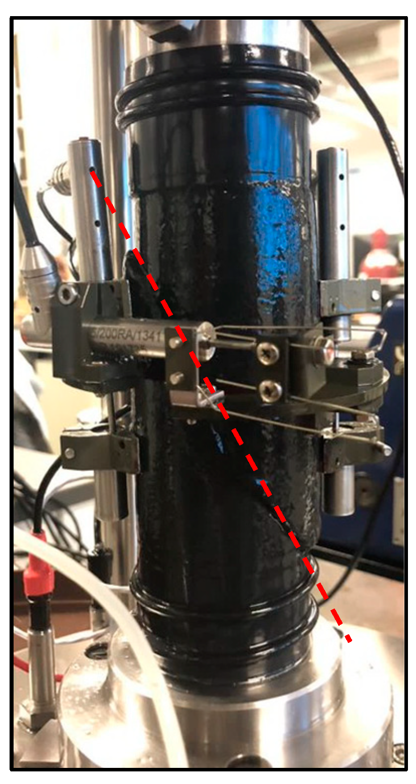
2.5.2. Compressional Shear Tests

Strain-controlled drained triaxial shear tests were conducted after RC testing to determine the large-strain mechanical properties of the HBS. Each HBS, with ~40% target hydrate saturation, was sheared at 500 kPa effective confining stress. Shearing was conducted at a strain rate of 0.1% per min with the PVC controller connected to the top of the specimen used to control pore pressure and ensure drained condition [49]. The following equations were used for determining deviatoric stress, q:
q = Q/Ac
A c = A 0 1 ε v 1 ε a
where Q = axial load given by load cell, and Ac is the corrected diametrical area, A0 = initial area, εa = axial strain, and εv = volumetric strain.
Local LVDTs attached to the specimen were used to record displacements from which axial and radial strains could be determined. Volumetric strains were calculated from axial and radial strains using the following equation [39]:
ε v = 1 + H π . L s i n π . L H . ε r + 3 8 sin π . L H 2 π . L H sin 2 π . L H 16 π . L H . ε r 2 . 1 ε a + ε a
where H is the specimen height and L is the gauge length of local axial LVDT. The ratio of H and L is assumed to remain constant throughout the triaxial test despite the changes in each of them [39].

3. Results

The details of specimens tested, which include initial porosities, hydrate saturations (Sh), and measured stiffness and strength from RC and triaxial tests, respectively, are provided in Table 2. All the specimens were subjected to RC tests during hydrate formation, cyclic strain excursions at the end of the hydrate formation period, and finally subjected to drained triaxial shearing.
At present, the impact of particle sizes on hydrate formation, morphology, and physical properties of hydrate-bearing sediments is not clear. It is highly unlikely that the sediments with different PSDs will behave the same way. Thus, this study focused on improving our fundamental understanding including the hydrate formation, evolution of geomechanical properties of hydrate-bearing specimens, and the final stiffness and strength for different formation paths.

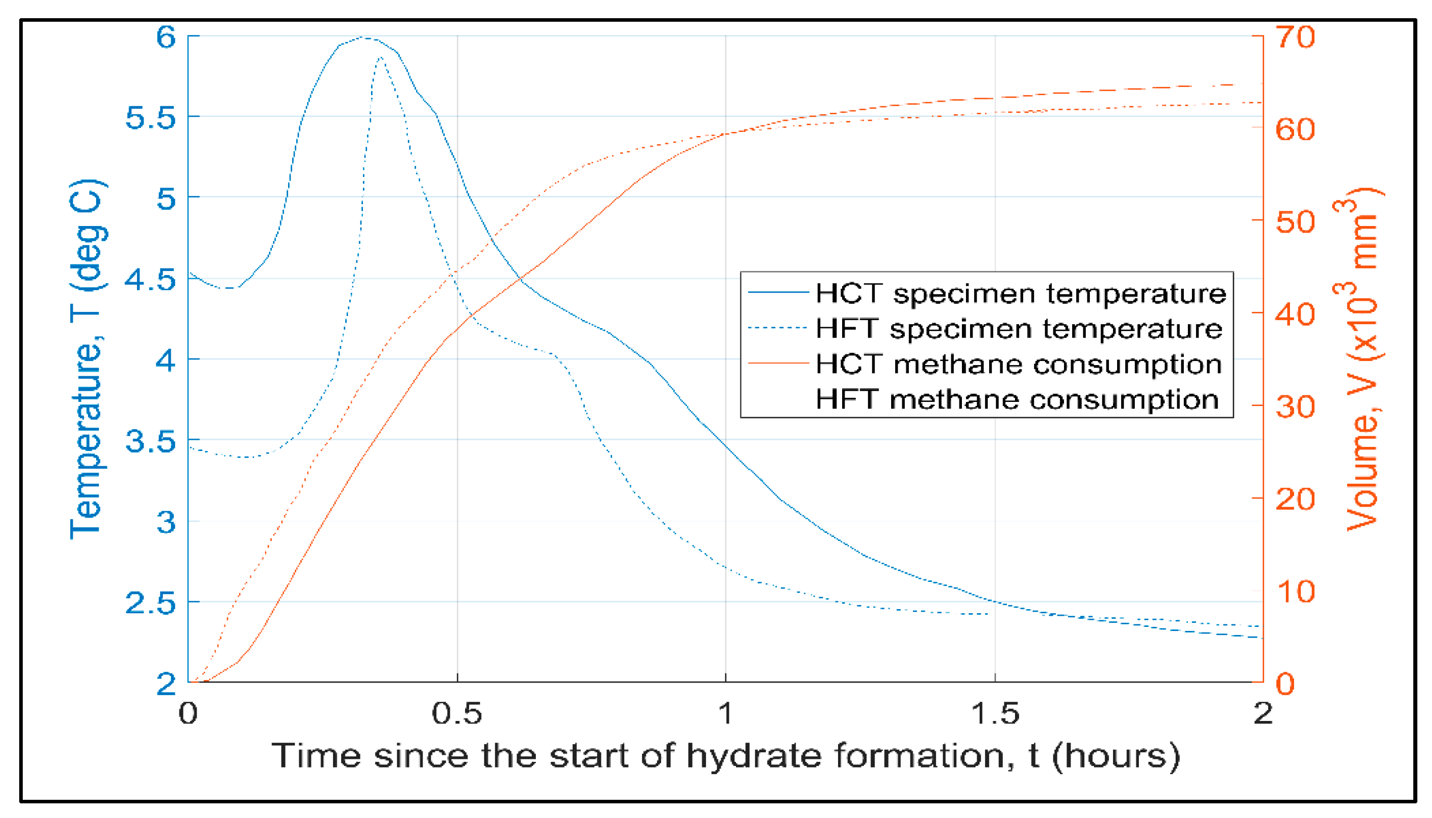
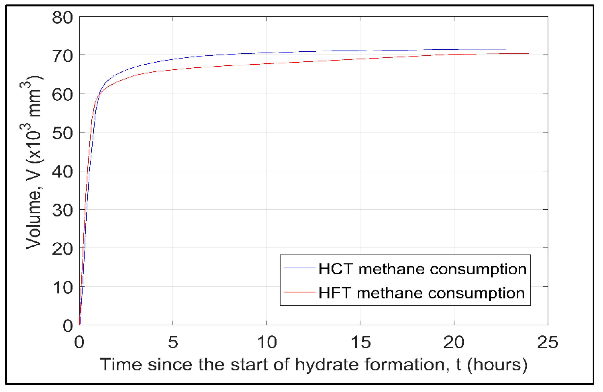
3.1. Hydrate Formation

Figure 5 shows the change in specimen temperature with time and the corresponding methane consumption measured during the hydrate formation stage using the ‘temperature-driven’ approach for specimen HFT. The system temperature is first reduced to ~7.5 °C (just outside the hydrate stability region) overnight, which leads to a minor increase in methane gas injected into the specimen to maintain a constant pore pressure as the temperature is lowered. The following morning (~12 h from the start of the test) the temperature was further reduced to ~2 °C. After ~14.5 h, a rapid increase in methane consumption rate is observed, indicating the onset of hydrate formation.
At this point, the temperature at the base of the specimen was ~3.5 °C (Figure 6), which suggests ~5 °C of sub-cooling from the bulk hydrate stability conditions (~8.5 °C for 6000 kPa) at the given pore pressure [50]. Shortly after the onset of hydrate formation, the specimen temperature starts to increase, even though cell temperature is reducing, up to a maximum of ~6 °C (around 20 min after the onset of hydrate formation). At this time the volume of gas consumed in forming hydrate is around ~52% of the total methane consumption measured when all hydrate was formed. The rate of methane consumption reduces significantly after around 45 min (from the start of hydrate formation) and coincides with a reduction in specimen temperature suggesting a rapid reduction in the rate of hydrate formation (exothermic heat of formation is unable to overcome the influence of cell temperature). At this point, ~80% of the total hydrate volume has formed. The rate of methane consumption continues to reduce until 100% hydrate formation is assumed after ~24 h. Although not shown, hydrate formation using a pressure-driven approach for specimen HFP shows a similar increase in temperature, which was observed around 20 min after the specimen pressure entered the hydrate stability region (for bulk hydrate). Subsequently, the temperature reduced to its initial temperature after approximately 1 h, highlighting somewhat similar hydrate formation behavior between the two formation methods.

Influence of Particle Size on Formation Rates

Figure 6 compares the methane consumption, and specimen temperature, with time, during the first 2 h of the hydrate formation stage for the two different sands using the temperature-driven approach. The time axis is shifted from Figure 5 to commence when a rise in methane gas consumption is first recorded for each specimen. In comparing the HCT and HFT specimens, differences in behavior can be observed. For specimen HCT, which has the coarser sand fraction, the methane gas consumption commences at a specimen temperature of ~4.5 °C which is ~1 °C higher than specimen HFT. This confirms earlier observations where smaller particle sizes increase capillary forces between particles that can lead to a greater degree of subcooling required for hydrate formation [51] and, therefore, longer induction period [52,53,54].
As the volume of methane gas increases, an increase in specimen temperature is observed (exothermic reaction for hydrate formation), with the onset of temperature increase for specimen HCT occurring before that of specimen HFT (even though a lower volume of methane gas consumed), which might be related to increased thermal conductivity through the coarser (larger) sand particles. The rate of initial hydrate formation is quicker in specimen HFT (greater volume of gas consumption) which leads to a greater temperature spike within this specimen (~2.5 °C increase compared to ~1.5 °C for specimen HCT), and the temperature spike occurring over a shorter period of time compared to specimen HCT. For specimen HFT, with smaller particles, a greater number of particle contacts would exist (for a given initial water content) with the corresponding increase in surface area and a greater number of nucleation sites compared to specimen HCT (for the excess gas method, available water for hydrate formation resides at particle contacts). As hydrate formation occurs at the gas-water interface this leads to the observed increase in the rate of formation for the finer sand (HFT) similar to that observed in other studies [55,56,57]. Another factor that can be considered is that further hydrate growth is related to the diffusion of gas through the hydrate rind into the water phase [58]. For the coarser sand (HCT), the reduced number of particles and associated nucleation sites would lead to greater volumes of water at particle contacts and therefore greater distance for gas diffusion as hydrate saturation increases after initial rind formation, which increases the time for ‘initial’ hydrate formation leading to the observed increase in the overall duration of temperature spike.

3.2. RC Testing

RC testing is a non-destructive test such that measurements can be obtained throughout the hydrate formation process to investigate how to hydrate growth influences the mechanical properties of the sand.

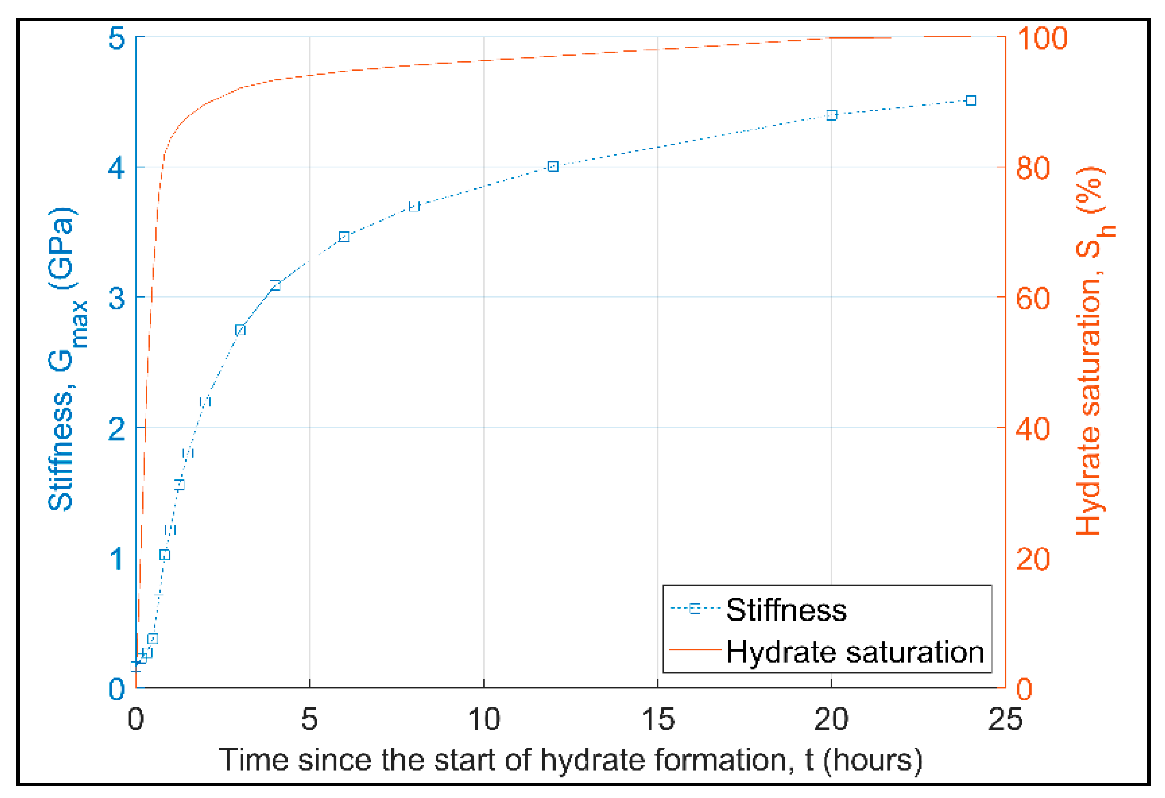
3.2.1. Evolution of Gmax with Hydrate Formation

Using the excess gas method, where hydrate forms from the free water that resides at grain contacts in the partially saturated sand and restricts particle movement, leads to an increase in shear stiffness (Gmax) of the sediment frame [43,59,60]. Figure 7 highlights the increase in Gmax that was calculated from the resonant frequency measured during RC testing at set times throughout the hydrate formation process for specimen HFT. Also shown for comparison is the volume of hydrate formed as a percentage of the total volume of hydrate determined at the end of the test. Although Gmax increases in line with the general increase in hydrate saturation, the rate of increase in Gmax differs significantly from the rate of increase in hydrate volume. During the first 30 min of hydrate formation, Gmax experiences a minor increase (~8% of final stiffness value), before increasing more rapidly. After two hours of hydrate formation, ~50% of the total increase in Gmax is observed, whereas hydrate content corresponds to ~90% of the total volume. Although the rate of increase in hydrate volume reduces significantly at this point, Gmax continues to evolve reaching 80% of its total magnitude around 8 h with the full conversion of hydrate and maximum Gmax assumed after 24 h. Thus, Gmax evolves slower than hydrate saturation. Similar trends were also observed in Gmax when the pressure-driven approach is utilized.

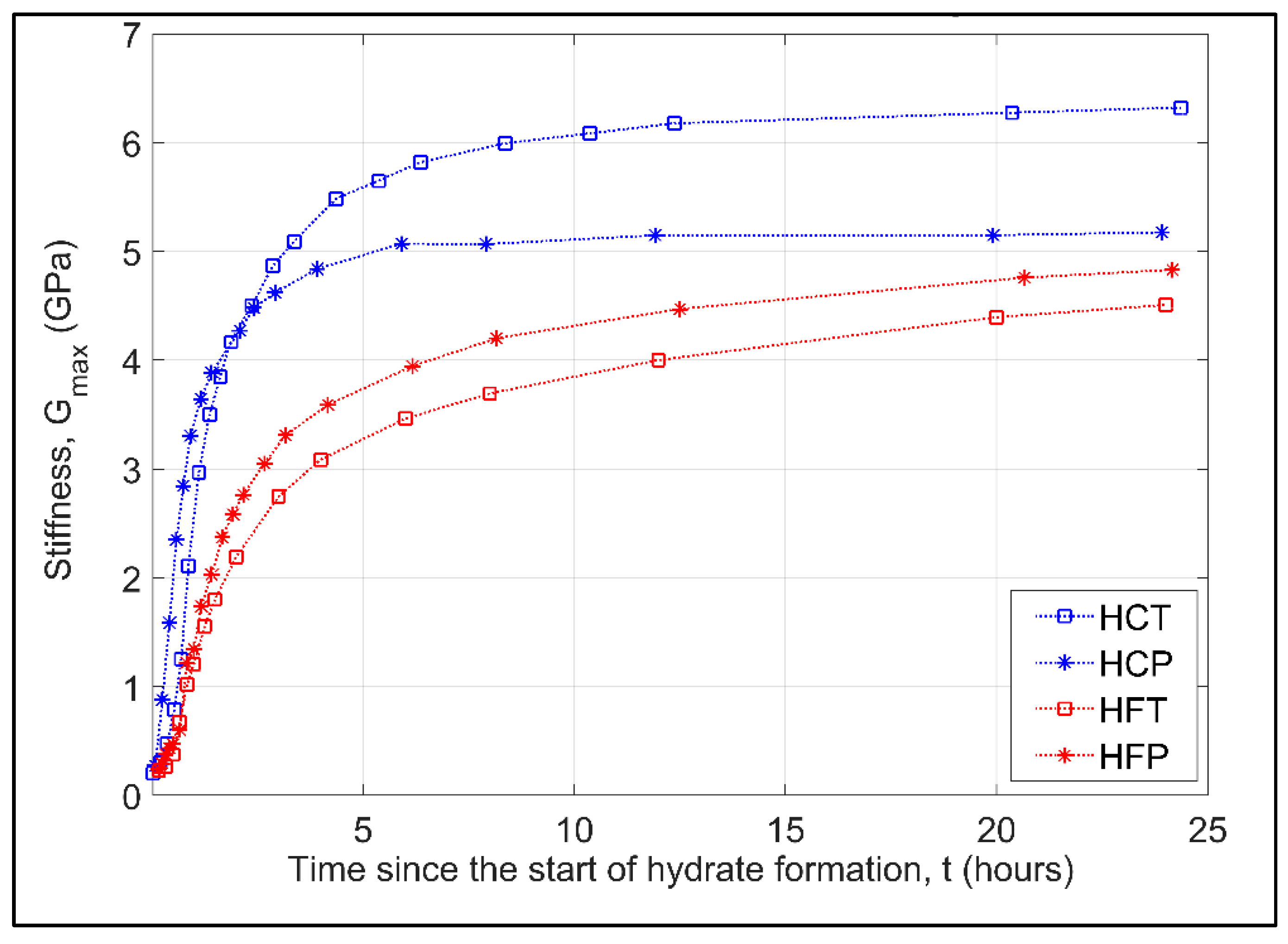
3.2.2. Influence of Particle Size Distribution on Evolution of Gmax

Before hydrate formation, Gmax measured for the six different specimens tested (see Table 2) varied from 0.170 GPa (HFT) to 0.205 (FS) with an average Gmax = 0.187 GPa. These minor differences in Gmax are likely to arise due to variations in the initial degree of suction generated due to the presence of free water at contacts, differences in porosity between specimens, and the inherent fabric and structure of grain contacts for each specimen. As hydrate is formed, all hydrate-bearing sand specimens exhibit similar trends in Gmax evolution (Figure 8) with a low initial increase in Gmax occurring over the first 30 min before a rapid increase is observed from 30 min to 2 h after the start of hydrate formation, with the rate of increase in Gmax thereafter, continually reducing until the end of the test. However, differences in both the rate of increase and the overall magnitude increase in Gmax are observed when comparing the coarse sands specimens to the finer sand specimens, and when comparing the difference in formation paths adopted.
As hydrate starts to form the rate of increase in Gmax occurs at a faster rate for the coarser sand specimens even though the total volume of hydrate is less (see Figure 6). In considering Figure 8, after ~1 h of hydrate formation specimen, HCT has an estimated Gmax = 2.97 GPa compared to Gmax = 1.35 GPa for specimen HFT, although at this time the total hydrate volume in each specimen is comparable (see Figure 9). The relative difference in Gmax continues to grow until around 8 h at which point Gmax for specimen HCT increases at a marginally slower rate compared to HFT. At the end of hydrate formation, a ~40% difference in stiffness is observed (Gmax = 6.323 GPa and 4.509 GPa for specimen HCT and HFT, respectively) with the finer sands giving lower stiffness, similar to the findings of Miyazaki et al. [37]. Although specimen HCT had a marginally higher hydrate saturation (~4%) that would lead to an increase in Gmax, the observed difference is significantly higher than previously reported values of shear stiffness as a function of hydrate saturations [59,60].

3.2.3. Influence of Hydrate Formation Approach on Evolution of Gmax

The overall increase in stiffness for each sand for the two different hydrate formation approaches is shown in Figure 10. The coarse sand specimens (HCT and HCP) exhibit the largest overall increase in Gmax compared to the fine sand (HFT and HFP), regardless of the hydrate formation approach adopted, which is also true for the rate of change in Gmax during hydrate formation (see Figure 8). In considering each sand individually, Gmax for HCT > HCP (6.323 GPa to 5.176 GPa), while the reverse is observed for the fine sand where Gmax for HFT < HFP (4.509 GPa to 4.833 GPa). This might suggest that the evolution of Gmax is somewhat insensitive to the hydrate formation approach adopted, and thus we might expect the same for natural field conditions regardless of whether the sediment is under the permafrost or below the sea floor. However, a significant variation in Gmax is observed for specimens where the temperature-driven approach was adopted (6.323 GPa and 4.509 GPa), while for the pressure-driven approach, the variation is much reduced (5.176 GPa and 4.833 GPa). Thus, it could be inferred that Gmax is insensitive to particle size when the pressure-driven approach is adopted, but sensitive to the temperature-driven approach. Therefore, there is a need for further studies which consider the relative impact of formation method and particle size on the stiffness of hydrate-bearing sands.

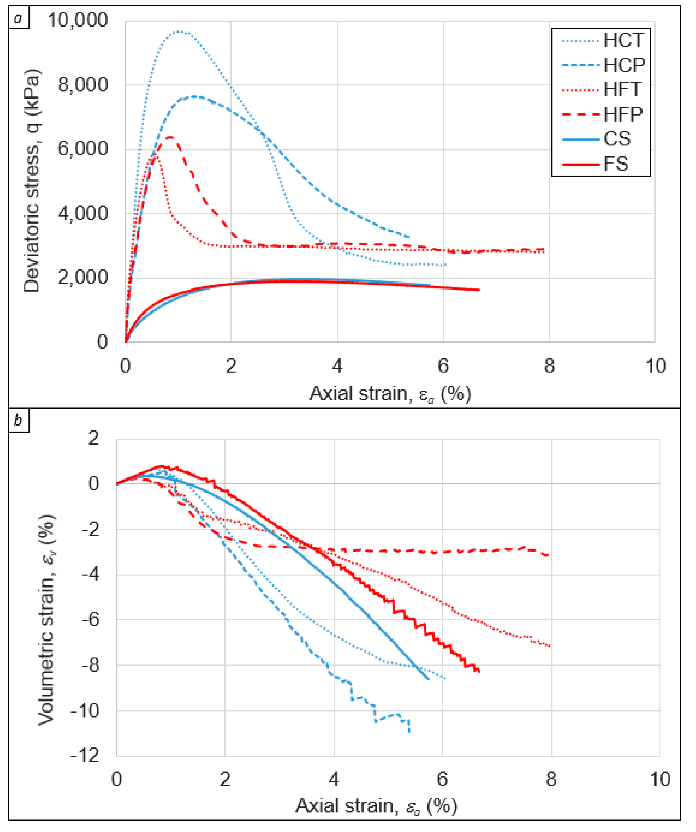
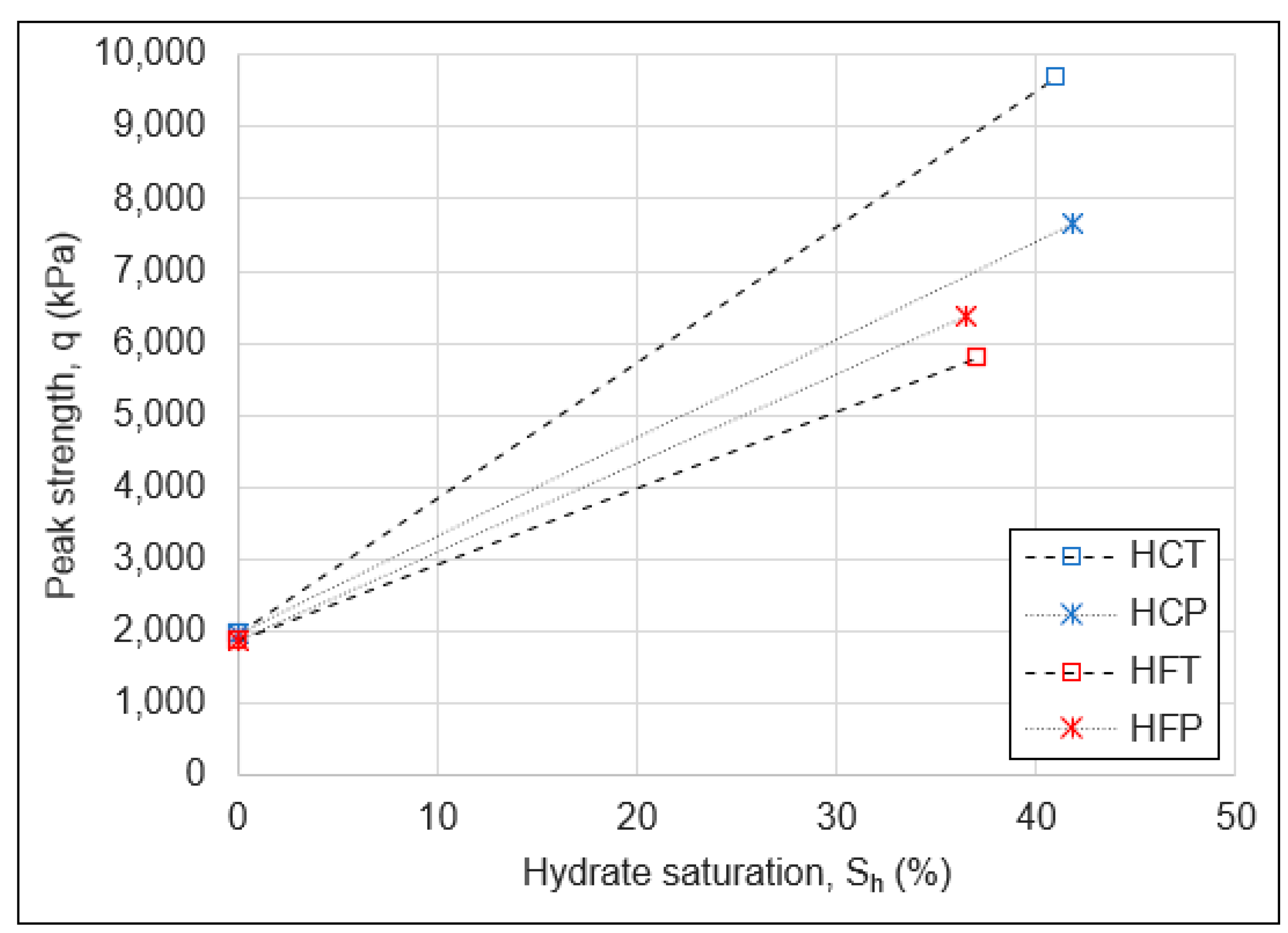
3.3. Triaxial Compression Tests

Figure 11 shows the deviatoric stress-axial strain response obtained from drained triaxial compression shear tests conducted on the two different sands, with and without hydrate (see Table 2), under an applied effective stress of 500 kPa. It is evident that the formation of gas hydrate within the pore space of each sand has a significant influence on the overall response compared to the same sand without hydrate in the pore space.
For the two types of sands with no hydrate in the pore space, similar behavior is observed. There is a gradual increase in deviatoric stress (q) with increasing axial strain (εa) up to a peak deviatoric stress (qpeak) with minor post-peak strain softening at higher εa. The CS specimen exhibits a peak deviatoric stress, qpeak = 1976 kPa (at εa = 3.5%), which is ~5% higher than that achieved for the FS specimen (qpeak = 1883 kPa at εa = 3.3%). The volumetric strain-axial strain response (Figure 11b) shows volumetric strains (εv) are initially compressive (+εv) before the specimens start to dilate (−εv). The specimen with larger particles (CS), which is denser than the finer specimen (FS), starts to dilate at εa = ~1.3% slightly ahead of the FS specimen (εa = ~1.8%), with the onset of dilation occurring before qpeak for both sands. The behavior exhibited by these sands is typical for non-cemented dense sands where the development of peak stress is related to the degree of dilation in the sand [61,62,63]. The slightly higher qpeak for the coarse sand, which occurs at a higher rate of dilation, compared to the fine sand, likely results from the slightly higher density (lower porosity) for the coarse sand specimens.

Influence of Particle Size Distribution and Formation Method on Stress-Strain Response of Hydrate-Bearing Sands

The formation of hydrate in the pore space of the sands, using the ‘excess gas’ method, has a significant impact on the stress-strain response of each sand. In addition, significant variations are observed between the two sands used even though they had similar hydrate saturation, and porosities, and were tested under very similar test conditions (effective stresses, temperature, strain rate). All the HBS specimens exhibit a significant increase in strength (given by qpeak) and stiffness (initial gradient of the stress-strain curve) compared to the sands without hydrate (Figure 11a) and show substantial post-peak strain-softening, highlighting the brittle nature of the HBS specimens. The peak strength is mobilized at much lower axial strains (εa = ~0.65–1.3%) compared to the 3.3–3.5% observed for the hydrate-free sands. It is also worth noting that for the HBS specimens no appreciable volumetric expansion is observed (Figure 11b) until after peak strength (εv ranges from −0.08% to +0.45% at qpeak).
Although the volumetric strains for the HBS and base sands appear to follow a similar behavior (Figure 11b), the reason for the ‘apparent’ dilation are different. For the sands without hydrate, radial strains develop due to the bulging of the specimen, with reasonably symmetric axial strains developing in the specimen. In contrast, for the HBS specimens, a discrete failure plane is observed (Figure 12) that is assumed to occur after the peak strength is exceeded. In this instance, the measured radial strains result from the sliding of rigid blocks, and axial strains can become highly unsymmetric depending on the relative position of each LVDT and the failure plane on the specimen.
The influence of particle size distribution on measured strength follows the same trend as observed for Gmax in that the coarse sand exhibits the largest increase in strength in comparison to the fine sand, along with a greater variation in values (see Figure 13). For the coarse sand qpeak = 7.66 MPa for specimen HCP and qpeak = 9.67 MPa for specimen HCT, which represents a ~3.9–4.9 fold increase in strength over specimen CS. However, for the fine sand qpeak = 5.80 MPa for specimen HFT and qpeak = 6.37 MPa for specimen HFP, which represents only a ~3.1–3.4 times increase in strength over specimen FS. The results presented confirm findings from testing of natural HBS cores [38] that appear to suggest that the sands particle size distribution has an appreciable impact on the strength of a HBS.
In comparing the impact of the hydrate formation procedure adopted, the coarse sand (specimen HCT) and fine sand (specimen HFT) where hydrate was formed using the temperature-driven approach differ in the peak strength by about 3.9 MPa with the coarse having higher strength. In contrast, for the pressure-driven approach, the difference between coarse sand (HCP) and fine sand (HFP) is only about 1.3 MPa, with coarse sand still showing higher peak strength. Similar to the discussion in Section 3.2.3 for stiffness, significant variation in the strength of the coarse and fine HBS was observed when the temperature-driven approach was utilized. The results suggest sensitivity of strength to the formation method where the pressure-driven method appears to have much less influence. Further studies are required to differentiate the exact interplay between the particle size distribution and formation method on the strength of hydrate-bearing sands.

4. Discussion

The results presented above show that the geomechanical properties of HBS are highly influenced by the formation of hydrate within the pore space of each sand, along with the particle size of the host sediment, and to some extent by the formation path adopted. In the following, we discuss some of the factors that may lead to the observed behaviors and respective differences.

4.1. Influence of Hydrate Formation on Stiffness Evolution

Recent studies have shown, using synchrotron x-rays [64,65], that during the early stages of hydrate formation (<10 min) rapid crystal growth occurs at the gas-water interface, with hydrate crystals growing to 10–20 μm in length. At the same time, smaller hydrate crystal growth was observed inside the water phase, suggesting that the growth of a hydrate rind at the interface did not appreciably hinder the transfer of gas molecules into the water phase. Furthermore, they observed that 35 min after the start of hydrate formation, when all hydrate was formed (in their tests), they could not observe individual crystals from x-ray images although they were able to discern a crystal size distribution from x-ray diffraction techniques broadly similar to that at ~10 min [65]. After two days, the hydrate crystals had coarsened, with the crystal size distribution being 40% broader than that observed after 35 min.
These observations can be used to infer the impact of hydrate formation and growth on stiffness evolution as seen in Figure 7 and Figure 8. Both sands exhibit a gradual increase in Gmax during the early stages of hydrate formation, which accelerates as hydrate volume increases up to 90% of total volume after around 2 h of hydrate formation, thereafter the rate of increase in Gmax slows considerably until the end of the test after 24 h. The slow increase in stiffness during the initial hydrate formation, which at 30 min equates to ~50% of the total hydrate volume, suggests the hydrate acts as a ‘pore filling’ component where the 10-20 μm hydrate crystals are starting to interact with each other on the outer hydrate rind as it grows and with smaller crystals in the water phase. Between 0.5–2 h, as the hydrate volume increases up to 90% of the total hydrate volume, Gmax increases rapidly and evolves to a more cementing behavior. This is likely to arise through coarsening and thickening of hydrate at the former gas-water interface [58], which leads to the stiffening of particle contacts as the hydrate formation proceeds [66], including filling up of the water phase with hydrate crystals such that deformation of the polycrystalline mass is restricted. The slow increase in Gmax for the remaining time of the experiment would suggest the slow coarsening of hydrate crystals and possibly the sintering of individual crystals that reduce crystal boundary dislocations and sliding. Although hydrate coarsening may continue for an extended time period (months, years) [65], our tests and others [67] have shown that the rate of increase in stiffness with time beyond 24 h is rather low.

4.2. Influence of Particle Size and Formation Method on Small-Strain Stiffness Behavior

It was observed that all specimens experienced a rapid increase in Gmax, with coarse sand specimens (HCT and HCP) seeing a more rapid increase in stiffness at the start of hydrate formation compared to the finer sand specimens (HFT and HFP). Furthermore, specimens HCT and HCP see a more rapid reduction in the rate of increase in Gmax after the majority of hydrate is formed compared to specimens HFT and HFP. This difference in Gmax evolution may result from local differences in water distribution within the sand, along with the change in morphology highlighted above. Considering this behavior, Figure 14 provides a schematic for the different hydrate distributions in the two sands considered to explain observed changes in stiffness.
Although water distribution, and therefore hydrate distribution, appears homogenous throughout the sand at the macroscale (Figure 3), it has been shown, through micro-CT imaging, that at the particle scale significant heterogeneity may exist [8,68,69,70]. This heterogeneity arises due to the distribution of pore sizes in the sands and the role of suctions. At low saturations, water resides as liquid bridges between contacts, and as water saturation increases the smaller pores become saturated in advance of invading larger pores [71]. Thus, during the forming of the unsaturated sand specimens at a constant water content the difference in pore sizes that occur between the coarse and fine sand specimens can affect the wetting of sand particles, location of water, water distribution around the grains, and at contacts, and ultimately the hydrate formation in pore spaces [68]. For the coarser sand, more water may exist at particle contacts, relative to the finer sand, where the smaller pores may become saturated with a corresponding reduction in water at larger grain contacts leading to a higher degree of patchy hydrate at the microscale. Thus, after hydrate formation, hydrate saturation at the particle scale may range from 0% to 100%, giving rise to a patchy hydrate distribution [64,72].
The influence of the hydrate on the stiffness of a sand specimen is dependent on where the hydrate will form. When hydrate forms from water at particle contacts, the hydrate will appear to bond grains [32], significantly increasing stiffness [59,73] as the rind thickens and free water is converted to hydrate (Figure 14a). However, if a pore is saturated, the increase in stiffness is slower since the relative size of the hydrate rind (that increases stiffness in the early stages) to the free water volume (see Figure 14b) is less than when hydrate forms at particle contacts. In addition, after complete hydrate formation, the overall stiffness of the pore-filled particle cluster may be high, but the reduced hydrate at adjacent pores (Figure 14c) will lead to a lower increase in stiffness for this group of particles. Therefore, as seen in Figure 8, the fine sand with a higher proportion of smaller pores compared to the coarser sand will see a reduced increase in stiffness during the early stages of hydrate formation (even though hydrate volume is somewhat higher during the early stages, see Figure 6). Furthermore, once all the hydrate is formed, the coarsening of those hydrate crystals in the saturated pores of the finer sand will lead to a greater rate of increase over a longer time compared to the coarse sand, although its overall magnitude is less. In addition to this potential impact, the increased patchiness that may be inherent in the finer sand may also contribute to the observed behavior.
Further validation of this conceptual model, where the majority of hydrate is formed in the first hour or so, with the subsequent formation and increase in sand stiffness arising due to the slow coarsening of grains, can be seen by considering the damping that is observed during a test. Damping in a soil specimen is due to the dissipation of energy, which is typically associated with viscous losses due to the ‘squirt flow’ of water [74]. Figure 15 shows a comparison between the change in stiffness, and the damping ratio, with time during the hydrate formation stage for specimen HFT. It can be seen that the damping ratio (D%) increases rapidly during the early stages of hydrate formation, reaching a value of ~4.8, which occurs after ~1 h of the start of hydrate formation when Gmax is ~1.2 GPa (25% of the final stiffness). After this time, D exponentially decays until D ~ 1% at the end of the test. The increase in damping is assumed to result from increasing viscous squirt flow of free water through the hydrate rind and between hydrate crystal contacts as hydrate forms [75,76]. As the hydrate saturation increases and free water in the specimen reduces, reduction in squirt flow occurs leading to the reduction in observed damping.
The variation in damping behavior for the two different sands is shown in Figure 16. It can be observed that the finer sands exhibit higher maximum damping compared to the coarser sands. This reinforces the view of more saturated pores in the finer sand leading to enhanced fluid squirt flow through the hydrate rind. It can also be observed that the rate of reduction in damping is faster in the coarser sand (~5 h) compared to the finer sand (~20 h), which again reinforces the viewpoint that in coarser sand more water proportionally resides at particle contacts than in fluid saturated pores and converts to hydrate quicker (faster reduction in water). The slow decay in damping after the majority of hydrate is formed, suggests that thin films of water exist between the small hydrate crystals that form from the bulk water phase that is slowly consumed as hydrate crystals coarsen (leading to a slow increase in stiffness at the end of the test). The slower decay in damping for the finer sand, therefore, arises due to the greater volume of water initially in saturated pores where hydrate crystal coarsening is greater than in sands with larger particles where the volume of rind to bulk water is greater.
The formation path appears to lead to significant differences in stiffness when the temperature-driven approach is adopted, although the differences are much reduced when the pressure-driven approach is considered. However, these observations are also influenced by the particle size distributions, and further studies are required to differentiate the effect of the formation method from particle size effects on stiffness.

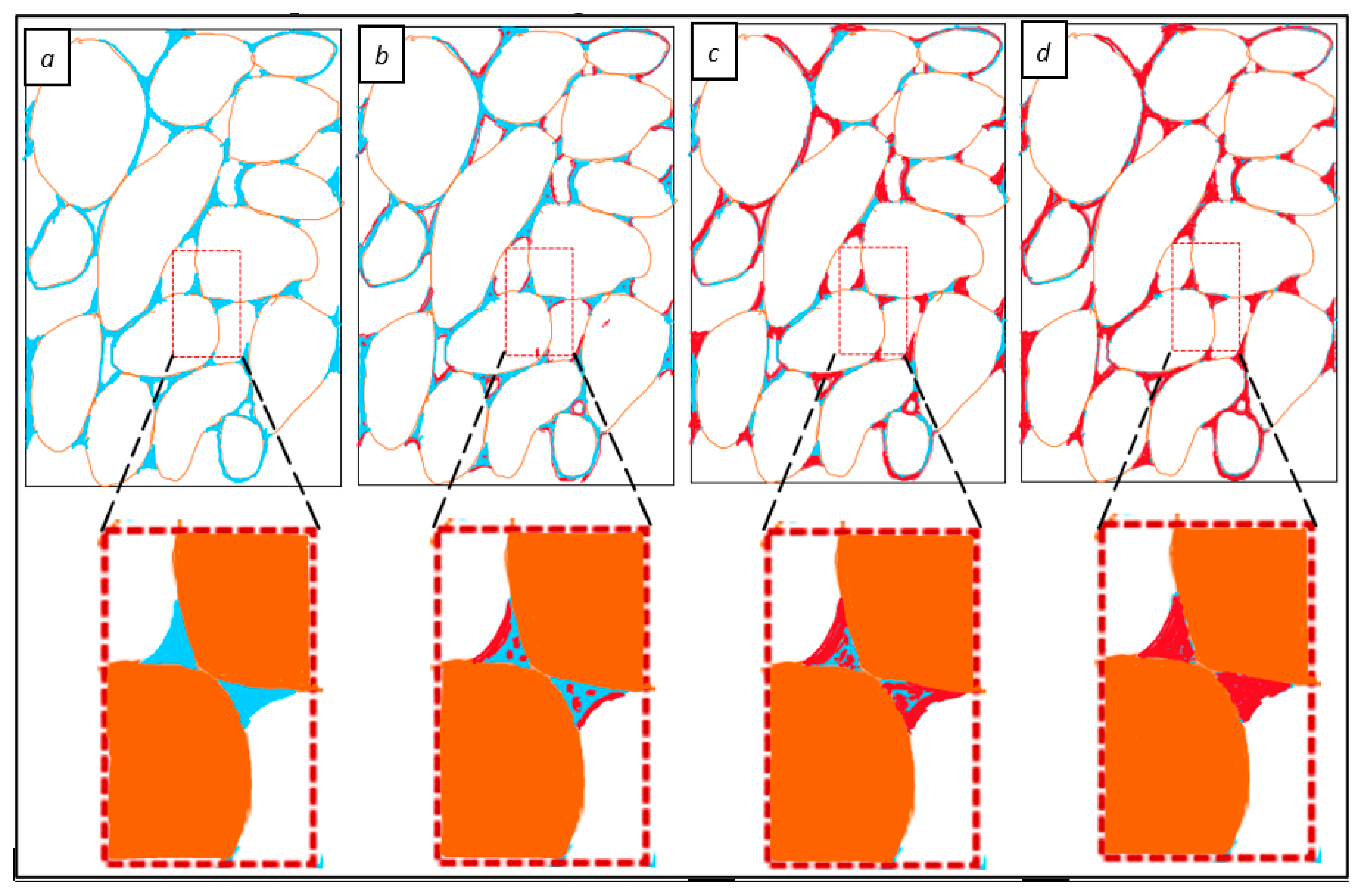
4.3. Influence of Particle Size and Hydrate Distribution on the Stress-Strain Response of Different Sands

The strength of a sand, which is derived from its stress-strain response, is a function of the inhomogeneous contact network that develops through the sand, with most of the external forces carried through the ‘force chains’ of sand particles [77,78,79]. The similarities in stress-strain response for the base sands (Figure 11) suggest that regardless of whether an inhomogeneous network develops, the macro response appears to be independent, with very similar strength being determined (Table 2). However, when hydrate forms in the pore space significant differences in the stress-strain response are observed, which suggests that the contact network, and the developed force chains, are sensitive to the location and distribution of the hydrate throughout the specimen, considering all other major factors (hydrate saturations, confining stress, strain rate) were kept constant.
The stress-strain response for HBS specimens is indicative of a cemented sand [80], where the breaking of bonds between sand particles and subsequent development of defined shear bands gives rise to the large increase in peak-stress at failure (qpeak) and post-peak strain softening, respectively. DEM modeling [81] suggests that the variation in peak strength between HBS specimens can be related to the cementation ratio, defined as the volume of cementing hydrate to pore-filling hydrate within the sand. In this modeling by Wang et al. [81], individual particles of hydrate are assumed to be either cementing particles or acting as pore filling. Hydrates in adjacent pores can also form a continuous hydrate structure and bridge the pore throat [8]. Therefore, particle contacts within a sand can range from uncemented contacts (Sh = 0%), cemented individual contacts, or patches of cemented particles (Sh = 100%). Thus, the force chains that develop during loading are likely to be strongly influenced by those force chains developing through either hydrate-hydrate, soil-hydrate, or soil-soil system [81]. Hence, the higher strength of the coarser sand (HCT and HCP) compared to the finer sand (HFT and HFP) further reinforces the hypothesis that more cemented particle contacts exist in sand with larger particles that lead to strong force chains during loading. In contrast, for the sands with smaller particles, where proportionally more hydrate may exist as pore-filling hydrate within the cluster of sand particles, and adjacent clusters experiencing less bonding (smaller volume of hydrate at particle contacts between clusters) such that the developed force chains will be easier to break during loading. Ultimately, the macro-properties and their variations are dependent on these microscale properties like the soil-hydrate interaction, hydrate distribution, and morphology.
Like stiffness measurements, the hydrate formation path adopted appears to have an influence on the measured strength, especially for the temperature-driven approach. However, the observed variations in strength also arise due to particle size distribution in each sand where the coarse specimens always have a higher value of peak strength. Therefore, there is a need for further studies to differentiate the relationship and quantify the degree of influence the formation method might have from the influence of particle size distribution.

5. Conclusions

This paper presents results from an investigation into the geomechanical behavior of HBS with different particle size distributions, and where the hydrate was formed using two different hydrate formation paths. Sand specimens were subject to resonant column testing and triaxial shear testing, to determine their small-strain stiffness and shear strength, respectively. Tests were conducted on base sands (without hydrate) and gas-saturated hydrate-bearing sands. To eliminate the influence of stress variations on measured stiffness and strength, all tests, including during hydrate formation, were carried out at an effective confining stress of 500 kPa.
The results from RC testing and triaxial shear tests show that only minor variations in stiffness and strength are manifest in the base sands (without hydrate), regardless of the particle size distribution of the sands. However, the formation of methane gas hydrate within each sand significantly increased the stiffness and strength observed highlighting the influence of hydrate being formed into the pore space. Stiffness measurements suggest that hydrate formation is rapid, with up to 90% of the hydrate formed within the first couple of hours, with further increases in stiffness over the remaining test period (24 h after the start of hydrate formation) resulting from hydrate grain coarsening. The hydrate-bearing sands with larger particles always exhibited higher stiffness and strength when compared to the sands with smaller particles, regardless of the formation paths adopted (pressure-induced or temperature-induced). Variations in measured stiffness and strength between all tests, with the largest observed for the specimens with larger particles, may have masked the potential impact of the hydrate formation path.
The greater increase in stiffness and strength in hydrate-bearing sands with larger particles highlights the impact of grain size distribution on these geomechanical properties, related to differences in pore-scale hydrate distribution. It is hypothesized that due to suctions the small pores in the smaller sand particles are fully saturated with a corresponding reduction in water at particle contacts in the bigger pores, such that a patchy distribution of hydrate occurs with a higher proportion of pore-filling hydrate. In contrast, a higher proportion of water may be distributed at contacts for larger particles, which leads to more cementing behavior. This hypothesis is supported by observed behavior, which includes a greater degree of subcooling required to initiate hydrate formation in the finer sand (increased suctions); a more rapid increase in stiffness for coarse sand (cementing hydrate); relatively moderate initial stiffness increase for finer sands (more patchy pore filling hydrate) with longer grain coarsening (more pore filling) highlighted by a greater relative increase in stiffness towards the end of the test. Damping measurements also supported this view.
Although HBS formed by temperature-driven method seem to have higher differences between geomechanical properties of coarse and fine sands, further studies are required to ascertain whether the variations in strength of HBS are related to the hydrate formation method or inherently related to microscale variations in hydrate distribution that impact overall force chain development during loading.

Author Contributions

Conceptualization, J.A.P., J.L.H. and M.R.P.; methodology, M.R.P., J.A.P. and J.L.H.; formal analysis, M.R.P., J.A.P. and J.L.H.; investigation, M.R.P. (literature and laboratory experiment review), J.A.P. and J.L.H. (literature); resources, M.R.P.; data curation, M.R.P. and J.A.P.; writing—original draft preparation, M.R.P.; writing—review and editing, J.A.P. and J.L.H.; visualization, J.A.P., M.R.P. and J.L.H.; supervision, J.A.P. and J.L.H.; project administration, J.A.P. and J.L.H.; funding acquisition—J.A.P., J.L.H. and M.R.P. All authors have read and agreed to the published version of the manuscript.

Funding

This research was funded by University of Calgary’s Eyes High Doctoral Recruitment Scholarship. We would like to thank Natural Sciences and Engineering Research Council of Canada (NSERC) and Canadian Research Chairs Program for their financial support.

Data Availability Statement

The data are available from the authors.

Acknowledgments

The authors thank the University of Calgary and Department of Civil Engineering for their support with physical space and technical personnel for carrying out the research.

Conflicts of Interest

The authors declare no conflict of interest.

References

  1. Kvenvolden, K.A. Methane hydrates and global climate. Glob. Biogeochem. Cycles 1988, 2, 221–229. [Google Scholar] [CrossRef] [Green Version]
  2. Milkov, A.V. Global estimates of hydrate-bound gas in marine sediments: How much is really out there? Earth Sci. Rev. 2004, 66, 183–197. [Google Scholar] [CrossRef]
  3. Boswell, R. Is Gas Hydrate Energy Within reach? Science 2009, 325, 957–958. [Google Scholar] [CrossRef] [PubMed]
  4. Boswell, R.; Collett, T.S. Current perspectives on gas hydrate resources. Energy Environ. Sci. 2011, 4, 1206–1215. [Google Scholar] [CrossRef]
  5. Wallmann, K.E.; Pinero, E.; Burwicz, E.; Haeckel, M.; Hensen, C.; Dale, A.; Ruepke, L. The global inventory of methane hydrate in marine sediments: A theoretical approach. Energies 2012, 5, 2449–2498. [Google Scholar] [CrossRef] [Green Version]
  6. Moridis, G.J.; Sloan, E.D. Gas production potential of disperse low-saturation hydrate accumulations in oceanic sediments. Energy Convers. Manag. 2007, 48, 1834–1849. [Google Scholar] [CrossRef] [Green Version]
  7. Torres, M.; Tréhu, A.; Cespedes, N.; Kastner, M.; Wortmann, U.; Kim, J.-H.; Long, P.; Malinverno, A.; Pohlman, J.; Riedel, M.; et al. Methane hydrate formation in turbidite sediments of northern Cascadia, IODP Expedition 311. Earth Planet. Sci. Lett. 2008, 271, 170–180. [Google Scholar] [CrossRef]
  8. Lei, L.; Park, T.; Jarvis, K.; Pan, L.; Tepecik, I.; Zhao, Y.; Ge, Z.; Choi, J.-H.; Gai, X.; Galindo-Torres, S.A.; et al. Pore-scale observations of natural hydrate-bearing sediments via pressure core sub-coring and micro-CT scanning. Sci. Rep. 2022, 12, 3471. [Google Scholar] [CrossRef]
  9. Moridis, G.; Collett, T.S.; Pooladi-Darvish, M.; Hancock, S.H.; Santamarina, C.; Boswell, R.; Kneafsey, T.J.; Rutqvist, J.; Kowalsky, M.B.; Reagan, M.T.; et al. Challenges, uncertainties, and issues facing gas production from gas-hydrate deposits. SPE Reserv. Eval. Eng. 2011, 14, 76–112. [Google Scholar] [CrossRef] [Green Version]
  10. Boswell, R.; Shipp, C.; Reichel, T.; Shelander, D.; Saeki, T.; Frye, M.; Shedd, W.; Collett, T.S.; McConnell, D. Prospecting for marine gas hydrate resources. Interpretation 2016, 4, 13–24. [Google Scholar] [CrossRef]
  11. Moridis, G.J.; Collett, T.S.; Boswell, R.; Kurihara, M.; Reagan, M.T.; Koh, C.; Sloan, E.D. Toward production from gas hydrates: Current status, assessment of resources, and simulation-based evaluation of technology and potential. SPE Res. Eval. Eng. 2009, 12, 745–771. [Google Scholar] [CrossRef] [Green Version]
  12. Dallimore, S.R.; Collett, T.S. Scientific Results from the Mallik 2002 Gas Hydrate Production Research Well Program, Mackenzie Delta, Northwest Territories, Canada; Geological Survey of Canada: Vancouver, BC, Canada, 2005; Web.
  13. Dallimore, S.R.; Yamamoto, K.; Waite, J.F.; Bellefleur, G. Proof of Concept for Gas Hydrate Production Using the Depressurization Technique as Established by the JOGMEC/NRCan/Aurora Mallik 2007–2008 Gas Hydrate Production Research Well Program. In Scientific Results from the JOGMEC/NRCan/Aurora Mallik 2007–2008 Gas Hydrate Production Research Well Program; Dallimore, S.R., Yamamoto, K., Waite, J.F., Bellefleur, G., Eds.; Geological Survey of Canada: Vancouver, BC, Canada, 2012; p. 601. [Google Scholar]
  14. Kumar, P.; Collett, T.; Yadav, U.; Boswell, R.; Cochran, J.; Lall, M.; Mazumdar, A.; Ramana, M.; Ramprasad, T.; Riedel, M.; et al. Geologic implications of gas hydrates in the offshore of India: Krishna-Godavari Basin, Mahanadi Basin, Andaman Sea, and Kerala-Konkan basin. J. Mar. Pet. Geol. 2014, 58, 29–98. [Google Scholar] [CrossRef] [Green Version]
  15. Yamamoto, K.; Terao, Y.; Fujii, T.; Ikawa, T.; Seki, M.; Matsuzawa, M.; Kanno, T. Operational overview of the first offshore production test of methane hydrates in the Eastern Nankai Trough. In Proceedings of the Offshore Technology Conference, Houston, TX, USA, 5–8 May 2014. [Google Scholar] [CrossRef]
  16. Yang, S.; Liang, J.; Lei, Y.; Gong, Y.; Xu, H.; Wang, H.; Lu, J.; Holland, M.; Schultheiss, P.; Wei, J. GMGS4 gas hydrate drilling expedition in the South China Sea. Fire Ice 2017, 17, 7–11. [Google Scholar]
  17. Flemings, P.B.; Phillips, S.C.; Boswell, R.; Collett, T.S.; Cook, A.E.; Dong, T.; Frye, M.; Goldberg, D.S.; Guerin, G.; Holland, M.E.; et al. Pressure coring of Gulf of Mexico deep-water turbidite gas hydrate reservoir: Initial results from The University of Texas—Gulf of Mexico 2-1 (UT-GOM2-1) hydrate pressure coring expedition. AAPG Bull. 2020, 104, 1847–1876. [Google Scholar] [CrossRef]
  18. Kurihara, M.; Ouchi, H.; Inoue, T.; Yonezawa, T.; Masuda, Y.; Dallimore, S.R.; Collett, T.S. Analysis of the JAPEX/JNOC/GSC et al. Mallik 5L-38 gas hydrate thermal-production test through numerical simulation. In Scientific Results from the Mallik 2002 Gas Hydrate Production Research Well Program, Mackenzie Delta, Northwest Territories, Canada; Geological Survey of Canada: Vancouver, BC, Canada, 2005; Web. [Google Scholar]
  19. Moridis, G.J.; Collett, T.S.; Dallimore, S.R.; Inoue, T.; Mroz, T. Analysis and interpretation of the thermal test of gas hydrate dissociation in the JAPEX/JNOC/GSC et al. Mallik 5L-38 gas hydrate production research well. In Scientific Results from the Mallik 2002 Gas Hydrate Production Research Well Program, Mackenzie Delta, Northwest Territories, Canada; Geological Survey of Canada: Vancouver, BC, Canada, 2005; GSC Bulletin 585; 21p. [Google Scholar]
  20. Moridis, G.J.; Reagan, M.T.; Boswell, R.; Collett, T.S.; Zhang, K. Preliminary evaluation of the production potential of recently discovered hydrate deposits in the Gulf of Mexico. In Proceedings of the Offshore Technology Conference, Houston, TX, USA, 3–6 May 2010. [Google Scholar] [CrossRef]
  21. Myshakin, E.M.; Seol, Y.; Lin, J.-S.; Uchida, S.; Collett, T.S.; Boswell, R. Numerical simulations of depressurization-induced gas production from an interbedded turbidite gas hydrate-bearing sedimentary section in the offshore India: Site NGHP-02-16 (Area-B). Mar. Pet. Geol. 2019, 108, 619–638. [Google Scholar] [CrossRef]
  22. Ouchi, H.; Yamamoto, K.; Akamine, K.; Kano, S.; Naili, M.; Tamaki, M.; Ohtsuki, S.; Kanno, T.; Tenma, N. Numerical history-matching of modeling and actual gas production behavior and causes of the discrepancy of the Nankai Trough gas-hydrate production test cases. Energy Fuels 2022, 36, 210–226. [Google Scholar] [CrossRef]
  23. Boswell, R.; Frye, M.; Shelander, D.; Shedd, W.; McConnell, D.R.; Cook, A. Architecture of gas-hydrate-bearing sands from Walker Ridge 313, Green Canyon 955, and Alaminos Canyon 21: Northern deepwater Gulf of Mexico. Mar. Pet. Geol. 2012, 34, 134–149. [Google Scholar] [CrossRef]
  24. Kida, M.; Jin, Y.; Watanabe, M.; Konno, Y.; Yoneda, J.; Egawa, K.; Ito, T.; Nakatsuka, Y.; Suzuki, K.; Fujii, T.; et al. Chemical and crystallographic characterizations of natural gas hydrates recovered from a production test site in the eastern Nankai Trough. Mar. Pet. Geol. 2015, 66, 396–403. [Google Scholar] [CrossRef]
  25. Dixit, G.; Ram, H.; Kumar, P. Origin of gas in gas hydrates as interpreted from geochemistry data obtained during the National Gas Hydrate Program Expedition 02, Krishna Godavari Basin, offshore India. Mar. Pet. Geol. 2019, 108, 389–396. [Google Scholar] [CrossRef]
  26. Moore, M.T.; Phillips, S.; Cook, A.E.; Darrah, T.H. Integrated geochemical approach to determine the source of methane in gas hydrate from Green Canyon Block 955 in the Gulf of Mexico. AAPG Bull. 2022, 106, 949–980. [Google Scholar] [CrossRef]
  27. Stern, L.A.; Kirby, S.H.; Circone, S.; Durham, W.B. Scanning electron microscopy investigations of laboratory-grown gas clathrate hydrates formed from melting ice, and comparing to natural hydrates. Am. Mineral. 2004, 89, 1162–1175. Available online: http://pubs.er.usgs.gov/publication/70026707 (accessed on 11 December 2021). [CrossRef]
  28. Priest, J.A.; Hayley, J.L. Strength of laboratory synthesized hydrate-bearing sands and their relationships to natural hydrate-bearing sediments. J. Geophys. Res. Solid Earth 2019, 124, 12556–12575. [Google Scholar] [CrossRef]
  29. Handa, Y.P.; Stupin, D. Thermodynamic properties and dissociation characteristics of methane and propane hydrates in 70-Å radius silica gel pores. J. Phy. Chem. 1992, 96, 8599–8603. [Google Scholar] [CrossRef]
  30. Henry, P.; Thomas, M.; Clennell, M.B. Formation of natural gas hydrates in marine sediments 2. Thermodynamic calculations of stability conditions in porous sediments. J. Geophys. Res. 1999, 104, 23005–23022. [Google Scholar] [CrossRef] [Green Version]
  31. Anderson, R.; Llamedo, M.; Tohidi, B.; Burgass, R.W. Characteristics of clathrate hydrate equilibria in mesopores and interpretation of experimental data. J. Phys. Chem. B 2003, 107, 3500–3506. [Google Scholar] [CrossRef]
  32. Kajiyama, S.; Wu, Y.; Hyodo, M.; Nakata, Y.; Nakashima, K.; Yoshimoto, N. Experimental investigation on the mechanical properties of methane hydrate-bearing sand formed with rounded particles. J. Nat. Gas Sci. Eng. 2017, 45, 96–107. [Google Scholar] [CrossRef]
  33. Masui, A.; Haneda, H.; Ogata, Y.; Aoki, K. Effects of methane hydrate formation on shear strength of synthetic methane hydrate sediments. In Proceedings of the 15th International Offshore and Polar Engineering Conference, ISOPE, Seoul, Republic of Korea, 19–24 June 2005. [Google Scholar]
  34. Yun, T.S.; Santamarina, J.C.; Ruppel, C. Mechanical properties of sand, silt, and clay containing tetrahydrofuran hydrate. J. Geophys. Res. Solid Earth 2007, 112, B04106. [Google Scholar] [CrossRef] [Green Version]
  35. Kneafsey, T.J.; Tomutsa, L.; Moridis, G.J.; Seol, Y.; Freifeld, B.M.; Taylor, C.E.; Gupta, A. Methane hydrate formation and dissociation in a partially saturated core-scale sand sample. J. Pet. Sci. Eng. 2007, 56, 108–126. [Google Scholar] [CrossRef] [Green Version]
  36. Hyodo, M.; Yoneda, J.; Li, Y.; Nakata, Y.; Yoshimoto, N.; Nishimura, A.; Song, Y. Mechanical behaviour of gas-saturated methane hydrate-bearing sediments. J. Geophys. Res. Solid Earth 2013, 118, 5185–5194. [Google Scholar] [CrossRef]
  37. Miyazaki, K.; Masui, A.; Sakamoto, Y.; Aoki, K.; Tenma, N.; Yamaguchi, T. Triaxial compressive properties of artificial methane-hydrate-bearing sediment. J. Geophy. Res. 2011, 116, B06102. [Google Scholar] [CrossRef]
  38. Priest, J.A.; Hayley, J.L.; Smith, W.E.; Schultheiss, P.; Roberts, J. PCATS triaxial testing: Geomechanical properties of sediments from pressure cores recovered from the Bay of Bengal during expedition NGHP-02. Mar. Pet. Geol. 2018, 108, 424–438. [Google Scholar] [CrossRef]
  39. Escribano, D.E.; Nash, D.F.T.; Diambra, A. Local and Global Volumetric Strain Comparison in Sand Specimens Subjected to Drained Cyclic and Monotonic Triaxial Com-Pression Loading; ASTM International: West Conshohocken, PA, USA, 2019; Volume 42. [Google Scholar] [CrossRef] [Green Version]
  40. Minagawa, H.; Ohmura, R.; Kamata, Y.; Nagao, J.; Ebinuma, T.; Narita, H.; Masuda, Y. Water permeability of porous media containing methane hydrate as controlled by the methane-hydrate growth process. In Natural Gas Hydrates—Energy Resource Potential and Associated Geologic Hazards; Collett, T., Johnson, A., Knapp, C., Boswell, R., Eds.; AAPG Memoir 89; U.S. Geological Survey: Reston, VA, USA, 2009; pp. 734–739. [Google Scholar] [CrossRef]
  41. Howard, J.J.; Hester, K.C.; Stevens, J.C.; Rydzy, M.B. Ultrasonic velocity measurements during experimental CH4 hydrate formation and CO2 exchange. In Proceedings of the 7th International Conference on Gas Hydrates, Edinburgh, UK, 17–21 July 2011; Curran Associates, Inc.: Red Hook, NY, USA, 2011. [Google Scholar]
  42. Bishop, A.W.; Green, G.E. The influence of end restraint on the compression strength of a cohesionless soil. Geotechnique 1965, 15, 243–266. [Google Scholar] [CrossRef]
  43. Priest, J.A.; Rees, E.V.L.; Clayton, C.R.I. Influence of gas hydrate morphology on the seismic velocities of sands. J. Geophys. Res. Solid Earth 2009, 114, B11205. [Google Scholar] [CrossRef] [Green Version]
  44. Collett, T.S.; Lee, M.W.; Agena, W.F.; Miller, J.J.; Lewis, K.A.; Zyrianova, M.V.; Boswell, R.; Inks, T.L. Permafrost-associated natural gas hydrate occurrences on the Alaska North Slope. Mar. Petrol. Geol. 2011, 28, 279–294. [Google Scholar] [CrossRef]
  45. Kvenvolden, K.A.; Lorenson, T.D. The global occurrence of natural gas hydrates. In Natural Gas Hydrates: Occurrence, Distribution, and Detection; Geophysical Monograph Series; Paull, C.K., Dillon, W.P., Eds.; AGU: Washington, DC, USA, 2001; Volume 124, pp. 3–18. [Google Scholar] [CrossRef]
  46. Sloan, E.D.; Koh, C.A. Clathrate Hydrates of Natural Gases, 3rd ed.; CRC Press, T&F Group: New York, NY, USA, 2007. [Google Scholar] [CrossRef]
  47. ASTM D4015-15e1; Standard Test Methods for Modulus and Damping of Soils by Fixed-Base Resonant Column Devices. ASTM International: West Conshohocken, PA, USA, 2017. [CrossRef]
  48. Drnevich, V.P. Resonant Column Test; Misc. Paper S-78-6; U.S. Army: Washington, DC, USA, 1978.
  49. Hyodo, M.; Yoshimoto, N.; Kato, A.; Yoneda, J. Shear strength and deformation of methane hydrate bearing sands with fines. In Proceedings of the 18th International Conference on Soil Mechanics and Geotechnical Engineering, Paris, France, 2–6 September 2013. [Google Scholar]
  50. Katz, D.L.; Cornell, D.; Kobayashi, R.; Poettmann, F.H.; Vary, J.A.; Elenbass, J.R.; Weinaug, C.F. Handbook of Natural Gas Engineering; McGraw-Hill: New York, NY, USA, 1959; 802p. [Google Scholar]
  51. Qin, Y.; Pan, Z.; Liu, Z.; Shang, L.; Zhou, L. Influence of the particle size of porous media on the formation of natural gas hydrate: A review. Energy Fuels 2021, 35, 11640–11664. [Google Scholar] [CrossRef]
  52. Sun, S.; Ye, Y.; Liu, C.; Wei, W.; Zhao, N.; Xiang, F.; Ma, Y. Research of methane hydrate formation process in quartz sand. Chem. Eng. Oil Gas 2011, 40, 123–127. [Google Scholar]
  53. Liu, W.; Wang, S.; Yang, M.; Song, Y.; Wang, S.; Zhao, J. Investigation of the induction time for THF hydrate formation in porous media. J. Nat. Gas Sci. Eng. 2015, 24, 357–364. [Google Scholar] [CrossRef]
  54. Li, X.-Y.; Li, X.-S.; Wang, Y.; Li, G.; Zhang, Y.; Hu, H.-Q.; Wan, K.; Zeng, H.-P. Influence of particle size on heat and mass transfer characteristics of methane hydrate formation and decomposition in porous media. Energy Fuels 2021, 35, 2153–2164. [Google Scholar] [CrossRef]
  55. Zhan, L.; Wang, Y.; Li, X.-S. Experimental study on characteristics of methane hydrate formation and dissociation in porous medium with different particle sizes using depressurization. Fuels 2018, 230, 37–44. [Google Scholar] [CrossRef]
  56. Liu, Y.; Li., L. Experimental study on the relationship between sediment particle size and composition and gas hydrate synthesis rate. Nat. Gas Geosci. 2020, 31, 176–183. [Google Scholar]
  57. Wang, Y.; Dong, S.; Zhan, J.; Wu, Q.; Zhang, P. Effect of quartz sand particle size on the formation and distribution of methane hydrate. Chem. Ind. Eng. Prog. 2020, 39, 3049–3056. [Google Scholar] [CrossRef]
  58. Sultaniya, A.; Priest, J.A.; Clayton, C.R.I. Measurements of the changing wave velocities of sand during the formation and dissociation of disseminated methane hydrate. J. Geophys. Res. Solid Earth 2015, 120, 778–789. [Google Scholar] [CrossRef]
  59. Priest, J.A.; Best, A.I.; Clayton, C.R.I. A laboratory investigation into the seismic velocity of methane gas hydrate-bearing sand. J. Geophys. Res. Solid Earth 2005, 110, B04102. [Google Scholar] [CrossRef]
  60. Sultaniya, A.; Priest, J.A.; Clayton, C.R.I. Impact of formation and dissociation conditions on the stiffness of hydrate-bearing sand. Can. Geotech. J. 2017, 55, 988–998. [Google Scholar] [CrossRef]
  61. Rowe, P.W. The Stress-Dilatancy Relation for Static Equilibrium of an Assembly of Particles in Contact. Proc. R. Soc. A Math. Phys. Eng. Sci. 1962, 269, 500–527. [Google Scholar] [CrossRef]
  62. Bolton, M.D. The strength and dilatancy of sands. Geotechnique 1986, 36, 65–78. [Google Scholar] [CrossRef]
  63. Coop, M.R. The mechanics of uncemented carbonate sands. Geotechnique 1990, 40, 607–626. [Google Scholar] [CrossRef]
  64. Chaouachi, S.H.; Falenty, A.; Sell, K.; Enzmann, F.; Kersten, M.; Haberthur, D.; Kuhs, W.F. Microstructural evolution of gas hydrates in sedimentary matrices observed with synchrotron X-ray computed tomographic microscopy. Geochem. Geophys. Geosyst. 2015, 16, 1711–1722. [Google Scholar] [CrossRef] [Green Version]
  65. Chaouachi, M.; Neher, S.H.; Falenty, A.; Kuhs, W.F. Time Resolved Coarsening of Clathrate Crystals: The Case of Gas Hydrates. Cryst. Growth Des. 2017, 17, 2458–2472. [Google Scholar] [CrossRef]
  66. Clayton, C.R.I.; Priest, J.A.; Best, A.I. The effects of disseminated methane hydrate on the dynamic stiffness and damping of a sand. Geotechnique 2005, 55, 423–434. [Google Scholar] [CrossRef]
  67. Priest, J.A.; Abbas, M.; Hayley, J.L. The change in geomechanical properties of gas saturated methane hydrate-bearing sand resulting from water saturation. J. Geophy. Res. Solid Earth 2021, 126, e2021JB022245. [Google Scholar] [CrossRef]
  68. Nguyen, N.N.; Galib, M.; Nguyen, A.V. Critical review on gas hydrate formation at solid surfaces and in confined spaces—Why and how does interfacial regime matter? Energy Fuels 2020, 34, 6751–6760. [Google Scholar] [CrossRef]
  69. Nikitin, V.V.; Geser, N.; Dugarov, A.; Duchkov, A.A.; Fokin, M.I.; Arkady Drobchik, N.; Shevchenko, P.D.; De Carlo, F.; Mokso, R. Dynamic in-situ imaging of methane hydrate formation and self-preservation in porous media. Mar. Petrol. Geol. 2020, 115, 104234. [Google Scholar] [CrossRef]
  70. Wu, P.; Yang, S.; Song, X.; Sun, X.; Li, Y. Influence of grain size distribution on the physical characteristics of cementing hydrate-bearing sediment. Energy Rep. 2021, 7, 8187–8197. [Google Scholar] [CrossRef]
  71. Willson, C.S.; Lu, N.; Likos, W.J. Quantification of Grain, Pore, and Fluid Microstructure of Unsaturated Sand from X-ray Computed Tomography Images. Geotech. Test. J. 2012, 6, 1–13. [Google Scholar] [CrossRef] [Green Version]
  72. Dai, S.; Santamarina, J.C.; Waite, W.F.; Kneafsey, T.J. Hydrate morphology: Physical properties of sands with patchy hydrate saturation. J. Geophys. Res. Solid Earth 2012, 117, B11. [Google Scholar] [CrossRef]
  73. Dvorkin, J.; Nur, A.; Yin, H. Effective properties of cemented granular materials. Mech. Mat. 1994, 18, 351–366. [Google Scholar] [CrossRef]
  74. Mavko, G.; Nur, A. Wave attenuation in partially saturated rocks. Geophysics 1979, 44, 161–178. [Google Scholar] [CrossRef]
  75. Chand, S.; Minshull, T.A.; Priest, J.A.; Best, A.I.; Clayton, C.R.I.; Waite, W.F. An effective medium inversion algorithm for gas hydrate quantification and its application to laboratory and borehole measurements of gas hydrate-bearing sediments. Geophys. J. Int. 2006, 166, 543–552. [Google Scholar] [CrossRef] [Green Version]
  76. Priest, J.A.; Rees, E.V.L.; Clayton, C.R.I. Attenuation of seismic waves in methane gas hydrate-bearing sand. Geophys. J. Int. 2006, 164, 149–159. [Google Scholar] [CrossRef] [Green Version]
  77. Drescher, A.; de Josselin de Jong, G. Photoelastic verification of a mechanical model for the flow of a granular material. J. Mech. Phys. Solids 1972, 20, 337–340. [Google Scholar] [CrossRef]
  78. Bathurst, R.J.; Rothenburg, L. Micromechanical aspects of isotropic granular assemblies with linear contact interactions. J. Appl. Mech. 1988, 55, 17–23. [Google Scholar] [CrossRef]
  79. Majmudar, T.S.; Behringer, R.P. Contact force measurements and stress anisotropy in granular materials. Nature 2005, 435, 1079–1082. [Google Scholar] [CrossRef] [PubMed]
  80. Coop, M.R.; Atkinson, J.H. The mechanics of cemented carbonate sands. Geotechnique 1993, 43, 53–67. [Google Scholar] [CrossRef]
  81. Wang, H.; Zhou, S.; Chen, Y.; Zhou, B.; Xue, S.; Zhu, X. Deformation mechanisms of coexistence type methane hydrate-bearing sands: A particulate-scale investigation. J. Nat. Gas Sci. Engr. 2022, 102, 104604. [Google Scholar] [CrossRef]
Figure 1. Schematic of ETAS and its components for the testing of hydrate-bearing specimens.
Energies 15 09632 g001
Figure 2. Image of formed sand specimen set-up on the ETAS base with the local instrumentation for measuring specimen displacement (LVDTs) attached along with external temperature sensor.
Energies 15 09632 g002
Figure 3. Water distribution measured over the length of a coarser sand specimen (a) Just after compaction, and (b) after complete test on hydrate-bearing sand.
Energies 15 09632 g003
Figure 4. Hydrate stability boundary and the respective paths followed to initiate hydrate formation (Point A represents final P-T condition for all the tests).
Energies 15 09632 g004
Figure 5. Change in temperature measured for specimen HFT, along with methane gas consumption, with time over the hydrate formation stage. The rapid increase in methane consumption once hydrate formation is initiated is followed by a temperature spike inside the specimen due to exothermic nature of hydrate formation.
Energies 15 09632 g005
Figure 6. Volume of methane consumed and the change of internal temperature of each hydrate-bearing sand specimen during first two hours of hydrate formation.
Energies 15 09632 g006
Figure 7. Stiffness evolution with hydrate content during hydrate formation stage for specimen HFT.
Energies 15 09632 g007
Figure 8. Change in stiffness during hydrate formation for the two different sands and two different formation paths utilized.
Energies 15 09632 g008
Figure 9. Comparison of methane gas consumption for HCT and HFT during the hydrate formation period (24 h).
Energies 15 09632 g009
Figure 10. Measured stiffness of sand specimens before hydrate formation, compared to the final stiffness measured 24 h after the onset of hydrate formation for the two different particle size distributions and two different formation paths utilized. The percentages above the bars represent hydrate saturation.
Energies 15 09632 g010
Figure 11. Stress-strain response of sand specimens with and without hydrate with (a) Deviatoric stress vs. axial strain, (b) Volumetric strain vs. axial strain. Dilation of specimen corresponds to −ve strains and +ve strains correspond to compression of the specimen.
Energies 15 09632 g011
Figure 12. Photograph of specimen HCT after triaxial shearing, showing distinct failure planes (denoted by red dashed line) that are similar to those observed for cemented granular material.
Energies 15 09632 g012
Figure 13. Measured peak strength for all sand specimens including base sands with no hydrate (FS and CS) and hydrate-bearing sand specimens formed using smaller sand particles (HFT and HFP) and larger sand particles (HCT and HCP).
Energies 15 09632 g013
Figure 14. Schematic of the conceptual model for water distribution and hydrate formation in coarse (Top set) and fine sand (Bottom set): (a) at the start of test and before hydrate formation where water (blue) distribution is more at the contacts for coarse sand (brown) versus around the grains and in smaller pores due to suction for fine sand, (b) just as the hydrate formation initiates, the more nucleation points (red) for fine sand lead to faster methane consumption initially, (c) thickening of hydrate rind and coarsening of hydrate, and (d) conceptual model for the hydrate distribution at the end of hydrate formation where there could still be bound water around the grains in fine sand, thus the lower value of stiffness and higher value of damping (see Figure 15 for stiffness evolutions and damping behavior) for hydrate-bearing finer sands compared to hydrate-bearing coarser sands (see Figure 16).
Energies 15 09632 g014aEnergies 15 09632 g014b
Figure 15. Increase in measured stiffness, Gmax (primary y-axis) and damping ratio (secondary y-axis) with time since start of hydrate formation.
Energies 15 09632 g015
Figure 16. Measured damping ratio for all hydrate-bearing sand samples.
Energies 15 09632 g016
Table 1. Basic soil properties.
PropertiesCS
(Coarser)
FS
(Finer)
Maximum void ratio (emax)0.820.87
Minimum void ratio (emin)0.440.49
Mean particle diameter (D50)0.45 mm0.25 mm
D100.12 mm0.10 mm
D901 mm0.8 mm
Table 2. Specimen properties, nomenclature, testing conditions, and measured parameters for specimens tested. CS and FS refer to the base sands without hydrate.
Specimen *Porosity
(%)
Hydrate Formation MethodHydrate Saturation, Sh (%)Initial Shear Modulus, Gmax (GPa)Final Shear Modulus, Gmax (GPa)Peak Deviatoric Stress, qpeak (kPa)
CS33.8-00.186-1976
HCT36.3Temperature driven410.1876.3239670
HCP34.3Pressure driven420.1835.1767656
FS36.3-00.205-1883
HFT40.2Temperature driven370.1704.5095797
HFP39.4Pressure driven360.1894.8336369
* C: Coarser (has larger particles and greater D50), F: Finer, H: Hydrate-bearing, T: Temperature driven formation path, P: Pressure driven formation path.
Publisher’s Note: MDPI stays neutral with regard to jurisdictional claims in published maps and institutional affiliations.

