1. Introduction
The demand for shipping around the world is rapidly growing with the need to support various supply chains and countries’ economies. It is reported that vessels in the maritime industry used approximately 300 million tons of fuel annually between 2007 and 2012 [
1]. Even though CO
2 emissions in the maritime industry are the lowest contributor when compared to other means of transport at approximately 2.8% of the global greenhouse gas (GHG) emissions [
2], there is a need to reduce the total annual GHG emission. The International Maritime Organisation (IMO) has introduced a stricter emission cap for sulfur, SO
x, and nitrogen oxide, NO
x, in MARPOL Annex VI Prevention of Air Pollution from Ships [
3] and announced the total GHG emissions have to be cut by at least 50% by 2050 compared to the 2008 level. The rules also designated sea areas as emission-controlled areas (ECAs) in which stricter controls were established to minimize airborne emissions from ships. These rules resulted in vessels seeking various means to achieve the stipulated target, such as utilising cleaner energy sources and installing scrubbers for removing SO
x and NO
x. As a result, technological advancement and commercial adoption in electrical or hybrid propulsion have seen an increase in popularity to achieve zero emission operation and improve vessel efficiency.
The shipping industry today shifts its focus to electrification decarbonisation and moving towards greener solutions. Following the trends in the automobile industry, hybrid electric propulsion systems have been proposed and used in ships to achieve higher efficiency, mitigate carbon emissions and reduce overall operational costs by combining traditional mechanical propulsion with electrical propulsion. Over the past few years, studies have been conducted on the diverse types of hybrid marine power systems to understand the behaviour of the ships at different operating and loading conditions to optimise the cost function of the hybrid system model. Respective studies adopted different hybrid propulsion power systems, however, all of which apply similar methodologies which will be shared later in this paper. This paper reviews the different hybrid marine systems available and the various energy management systems (EMS) and control strategies adopted to optimise power management, reduce fuel consumption, and mitigate carbon emissions.
The following sections will be arranged as follows;
Section 2 presents an overview of the different propulsion systems available;
Section 3 covers an overview of the methodology used to obtain vessel loading profiles and the different approaches for system optimisation;
Section 3 presents the comparison of the system results with respect to the carbon emissions and operation cost.
Section 3 also presents a comparison of the different energy sources available for diesel.
Section 4 discusses the challenges and other possible areas for future studies. Finally,
Section 5 provides a summary and conclusion for this review.
2. Ship Propulsion Systems
2.1. Propulsion System
Past studies have been extensively documented on several types of marine propulsion systems, specifically, diesel–mechanical powered [
4,
5] and diesel–electric [
4,
6,
7,
8] powered vessels. This section provides a brief description of those systems followed by fully electric and hybrid power systems, their advantages and disadvantages, as well as some notable studies performed.
2.1.1. Diesel–Mechanical Propulsion System
The diesel–mechanical propulsion system is the most conventional system currently used in most marine vessels due to its simplicity and relatively high reliability. The diesel internal combustion engine is the main primary source of the propulsion system [
4]. Power generated from the engine cylinders is directly transferred to the mechanical movement of the crankshaft with the propeller through a gearbox to drive the propulsion system, as shown in
Figure 1 [
5]. The gearbox is required for smaller ships to reduce engine speed and reverse shaft rotation; however, it is not required for large ships as reversing can be performed by reversing the engine rotation. Fixed-pitch propellers are the most applied propulsor, but they require a reversible engine or gearbox to stop and for reversing manoeuvres. Using a controllable pitch propeller, on the other hand, can produce negative thrust to stop and reverse by changing the position of the blades. For simplicity, the system model considered in this review paper adopts the fixed-pitch propeller configuration.
The power required for the other services of the vessels such as heating, ventilation and air conditioning (HVAC), as well as lighting will draw power from an auxiliary engine connected to an alternating current (AC) distributor. The main and auxiliary engines are fuelled by marine diesel oil (MDO)/heavy fuel oil (HFO). However, many ships’ systems are not able to handle the heavy residual from HFO, thereby these fuels are blended to produce fuel oil that is more suitable for use in ships, known as intermediate fuel oil (IFO). IFO is used to improve the viscosity and density of vanadium content, carbon content, and other characteristics of HFO [
4]. The use of IFO generates a lower cost as compared to utilising a better-grade fuel oil for the system, such as very low-sulfur fuel oil with a maximum sulfur emission of 0.5% or ultra-low-sulfur fuel oil with a maximum sulfur emission of 0.1%.
Relevant studies on the carbon emissions and the cost function of the diesel–mechanical propulsion system can be found in [
9], where a comparison study was conducted on the life cycle assessment of a diesel engine-powered ship to a battery-powered ship. The results showed that diesel engine-powered ships emit 56% more CO
2 equivalent per nautical mile (CO
2-eq/nm) as compared to their battery-powered counterparts. Another life cycle assessment study by Wang et al. [
10] comparing tugboats with different configurations of propulsion systems was conducted to investigate the optimal system with the lowest emission, cost, and hazard impacts. Three medium engines, each rated at 1062 kW, were found to consume the least fuel oil at 24,680 tonnes equivalent to the cost of 15.5 million Euros as compared to 25,360 tonnes of a conventional two large engine configurations each rated at 1518 kW. Other means to reduce emissions and fuel consumption could be achieved by reducing the operating horsepower. However, lowering the horsepower may not be able to fulfil the service speed or bollard pull requirement [
5].
The use of scrubbers is recommended for the removal of sulfur emissions of more than 95% at all engine loads, however, scrubbers are ineffective for reducing the emission of NO
x and CO
2, where a lower emission to higher engine load trend was observed [
11]. By using exhaust gas recirculation, NO
x emission could be reduced by up to 76%, however, it does not reduce CO
2 emissions, due to the increase in engine temperature and dilution effects [
12]. It is to note that the dilution effects are due to the results of the dilution of oxygen concentration. This thus increases the CO
2 emissions as more exhaust gas is recirculated into the cylinder, thereby causing more oxygen to be displaced.
Benefits and Challenges of Diesel–Mechanical Propulsion
The greatest advantage of using this system, is the direct mechanical connection between the main engine to the propeller, resulting in minimal transmission losses [
6]. The purchase cost of mechanical propulsion is cheaper than other systems due to its simplicity. Mechanical diesel propulsion operates most efficiently at 80–100% of the designed speed [
13]. Ideally, vessels operating with limited operating profiles such as cargo ship travelling at single cruising speed benefits from diesel–mechanical propulsion due to the simplicity of the configuration and least dynamic engine loading.
The disadvantages of the system are poor fuel efficiency, high emissions when sailing at speed below 70% of top speed and fuel consumption significantly increases when rated power is below 50% [
13]. A simple diesel–mechanical propulsion system provides no fallback plan, thereby failure of any components along the drive train results in loss of propulsion. The energy management of the engine is simple because it requires both systems to operate simultaneously, regardless of the power required. The dynamic loading also leads to an increase in the maintenance required for the engine. This could be overcome by the addition of an appropriate control strategy and alternatively using a controllable pitch propeller that can result in a reduction in the need for maintenance and improvement in manoeuvrability [
14].
2.1.2. Electrical Propulsion System
The movement towards electrical propulsion has dated back as early as the 1990s [
15] for cruise ships and naval vessels. Electrical propulsions are known to be more efficient in low-speed conditions, and it introduces conversion losses from 5–15% propulsion power due to the additional electrical components such as generators, power converters, transformers, and electric motors. Today electrical propulsion systems in vessels are crucial specifically for vessels operating in emission control areas (ECAs), as a significant amount of carbon emission could be effectively mitigated. The market in electrical propulsion ships for North America (blue), Europe (turquoise), Asia Pacific (green), and the rest of the world (yellow) is expected to increase over the next few years and grow by approximately USD 11.5 billion between 2021 and 2030 as shown in
Figure 2 below [
16].
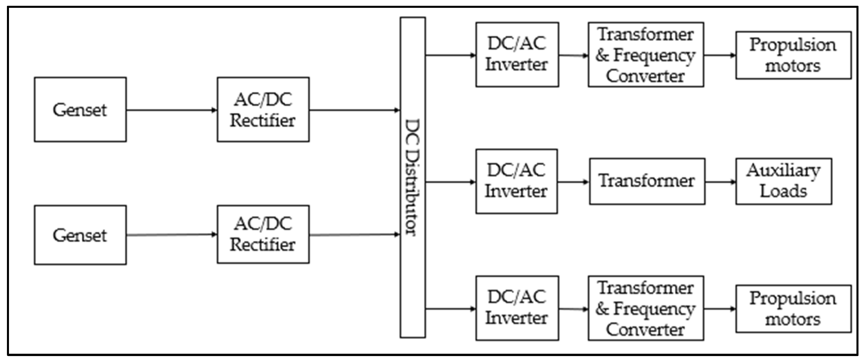
A direct current (DC) distribution is selected over an alternating current (AC) distribution because conversion between the transformer and main switchboards is eliminated, resulting in a smaller equipment footprint with up to 25% of the electrical component weight reduced for a platform supply vessel [
17]. A standard DC distribution electric propulsion power system is shown in
Figure 3. Several generator sets (Gensets) feed a fixed-frequency high voltage towards the electrical bus selector through an AC/DC rectifier to convert AC power from the Gensets to DC. The bus then feeds through a transformer and frequency converter to control the shaft speed and the required electrical power to the electric propulsion motor drive. Frequency converters may include both an AC–DC rectifier and a DC–AC inverter. This enables the electrical energy to be delivered and returned to the bus. DC electrical power from the bus selector feeds through the transformer and inverter to provide AC electrical power to other services and hotel loads. Another benefit of using DC over an AC distribution system is the redundancy for synchronisation. Synchronisation is required for parallel power sources for frequency, voltage, and phase to be the same before connecting to the power system. However, in a DC system, the phase and frequency do not need to be the same since the AC–DC rectifier produces a faster power generation response time [
18].
AC electricity is used to distribute lighting and hotel loads because the load uses a constant frequency and low voltage [
19]. As for propulsion, an AC–DC rectifier is used to generate DC power because the coupling between network frequency and engine speed is removed allowing a varied speed operation. This results in a 60–100% improvement in fuel efficiency due to the enhancement in the engine’s combustion process [
20]. The freedom to control each power utilised in the propulsion system opens the opportunity to optimise fuel consumption and also reduces the maintenance load since the engine can be switched off when not required. The propulsion transformer is required to reduce the total harmonic distortion (THD) level to comply with the classification’s requirement [
21].
Alternatively, instead of using Gensets, DC distribution supports the integration of energy storage such as batteries and renewable energy sources for more fuel savings and reduces life cycle and maintenance costs such as by the use of fuel cells. Batteries such as lithium-ion and nickel–cadmium for their rechargeable properties; however, lithium-ion batteries are more commonly found in fully electric power systems today due to their higher energy density and developments. An overview of fuel cells for maritime applications has been covered extensively by van Biert et al. [
22]. Fuel cell research now focuses on renewable resources such as hydrogen, methanol, and LNG [
23], which will be covered later in this section.
Benefits and Challenges of Electric Propulsion
The benefits of DC distribution electric propulsion systems have been described in
Section 2.1.2. In summary, the benefits of using fully electric propulsion are as follows:
lower transmission losses
reduction in weight and space occupied in a ship
improve propulsion efficiency and reduction in fuel and emissions
simpler configuration of generators
able to implement other energy storage
The electric propulsion system is usually complemented by a power management system (PMS) to optimise the distribution of loads. This is because an incorrect power supply and demand can result in the shutdown of the electrical system since power sources are connected to the same electrical network. Aside from that, PMS can be used to monitor the load and power available to trigger when to start and stop the Gensets. With the several conversions in the power stages, an increase in losses in its specific fuel consumption at the top speed of the ship occurs to the electrical propulsion [
13].
However, the development of an optimised PMS to achieve the diverse operation load profile and the hotel load is challenging as it depends on many parameters such as fuel consumption, power, and engine RPM, which have to be obtained from sensors and are usually not readily available. An addition of a control strategy for the electrical network is required to maintain the voltage and frequency stability of the system, load distribution among the Gensets, and blackout preventions [
24]. Although electric propulsion promises a reduction in fuel consumption and emissions, operating the Gensets to achieve higher propulsion requirements, for specific tugging operations or strategic manoeuvring, leads to poor fuel consumption and higher emissions.
2.1.3. Hybrid Propulsion System
Most ocean-going marine vessels such as cruises, ferries, and offshore support vessels (pipe-laying vessels) and warships use diesel–electric propulsion. An estimated fuel saving of 17% [
25] could be achieved by using diesel–electric as compared to using diesel–mechanical propulsion. Hybrid propulsion with effective control strategies can reduce fuel consumption and emission by 10% to 35% [
13]. This paper covers two different types of hybrid diesel propulsion systems, i.e., diesel–electric powered by Gensets and diesel–electric powered by battery.
Diesel–electric powered by Gensets, as shown in
Figure 4a, consists of a direct mechanical drive such as a diesel engine to provide high speeds connecting through a gearbox and to the propeller. Additionally, an electric motor coupled with the same gearbox or directly to the propeller could be used to provide propulsion for lower speeds and avoid overloading the main engine. Similarly, the motor acts as a generator for electric loads to other ship components. With the diesel engine, the system can produce power from either the electric generator or the Gensets. Ideally, a system of such complexity requires a rule-based control to determine the capacity required.
Another variation of diesel–electric propulsion using battery or fuel cells is presented in
Figure 4b. The system configuration is similar to
Figure 4a but with an additional stored power supply such as a battery connected to the main distribution. The use of batteries as energy storage is adapted from the automotive industry, but the energy storage used in the automotive industry focuses on storing brake energy instead of using the energy to run the engine more efficiently [
26]. Therefore, the energy storage in the ship enables maximum energy efficiency to be achieved with the flexibility of combining and switching the power consumption between the diesel engine and the electric energy from the Gensets and battery, respectively. The motor coupled with the gearbox enables the option of using the electrical drive to propel the vessel for low-speed manoeuvring. This has a clear advantage if compared to a diesel–mechanical propulsion system, which requires the gearbox to slow down the vessel, because there may be risks in overloading the engine and adding up to more maintenance cost for the mechanical propulsion system. The use of fuel cells with diesel engines or gas turbines can achieve high efficiencies by using more energy-dense fuels [
22]. The complex control strategies of the hybrid system are important with the increasing level of complexity in the load-sharing profiles; a summary of these control strategies will be discussed in the later section.
Benefits and Challenges of Hybrid Diesel Propulsion
Hybrid diesel propulsion combines the benefits of both the electrical and mechanical components highlighted in
Section 2.1.1 and
Section 2.1.2, respectively. However, a well-designed control strategy is still required to optimise these benefits, allowing electrical energy to be transferred from mechanical components to the electric component and vice versa.
Diesel–electrical propulsion has advantages in its ease of maintenance since electrical compliances occupy a smaller footprint as compared to mechanical components and allow for more flexibility in the positioning of the thrusters or any other mechanical equipment. The number of Gensets to operate can be controlled based on the power demand to improve fuel efficiency and engine loading. This then allows the diesel–electrical propulsion to provide a redundancy measure, where the other generators will be able to provide the necessary power load requirements in case of an engine failure [
24]. The batteries installed onboard the vessel enable load levelling between the power fluctuation that occurs when vessel speed increases, thus leading to a more efficient operation, a method known as the peak shaving strategy. The peak shaving strategy from the battery, which is a method for the battery to deliver power during times when high power is required for a smoother operation and recharge when less power is required, can allow the engine to run more efficiently [
27]. The energy storage can be recharged with the “charge-discharge mode” when the engine is operating with lesser fuel consumption to reduce emissions and save fuel [
28]. Shore power can also be used to charge the batteries and as an alternative power source when ships are docked. The batteries can also act as a backup if a power failure or diesel generator malfunction occurs. This would ensure a continuous supply of electricity without disruption.
There are, however, some challenges of a hybrid propulsion system in the charging and discharging of the battery. A control strategy has to be designed and adopted to maximise the reduction in fuel consumption and carbon emissions. The control strategy selected should be able to dynamically optimise the load of the battery and engine. The power management control strategies available are discussed in
Section 3.3.
2.2. Control Strategies
Control strategies are required in any electrical propulsion with an AC or DC distribution system. A comparison of AC and DC distribution control strategies is shown in
Table 1, both systems with droop control as the most promising primary control strategy when compared to heuristic control or equivalent consumption minimization strategy in which the droop control demonstrates a reduction in fuel consumption of 5–10% [
13]. Speed droop control and voltage droop control are the types of droop control available in the system; each operates in a similar methodology but with different inputs.
Droop control is important to maintain the stability of an AC distribution network with two or more Gensets connected. On the other hand, speed droop controls the load sharing of power between active Gensets in parallel. It is used in the engine governor to control the engine speed, with the governor increasing the fuel to bring the engine speed back to the original speed. However, an overshoot in engine speed may occur due to inertia and power lag, hence the governor helps to respond by providing less fuel to reduce the engine speed. In layman’s terms, the droop control controls the increase in governor speed when the load decreases and vice versa. The amount of droop can be calculated based on Equation (1) [
24]. Ideally, the recommended droop is to be set between 3% to 5% [
29].
where no load speed is the speed of the generator when there is no power going through the generator and full load rated speed is the speed at maximum power. Generally, an increase in load will result in a decrease in the frequency speed of the generator. Similarly, a voltage droop control is used to control the load-sharing power between simultaneous active generators in parallel where an automatic voltage regular in the generator controls the output voltage of the Genset. The formulation to obtain the voltage droop is given in Equation (2), which is similar to Equation (1) but with speed replaced with voltage, where no load voltage represents the highest allowable load value of the voltage for the generator at the current nearing zero. The load will be the lowest with a higher current at full load-rated voltage.
2.3. Renewable Energy Sources
The DC distribution in hybrid propulsion could be designed to integrate with other sources of renewable energy fuels, such as hydrogen and liquified natural gas (LNG).
Figure 5 shows the system power flow configuration of a hybrid propulsion system with LNG engines. When it comes to system modelling, a gas turbine model (GAST) is commonly used for dynamic models of power system components in simulation programs to simulate the power system behaviours of the gas engine, which was once Western Electricity Coordinating Council (WECC) compliant [
30,
31]. GAST models are used to simplify the gas engine process; however, the temperature control loop will be inactive as it leads to operational inaccuracy [
32]. Since 2001, a more accurate model such as GGOV1 has superseded the GAST model. Similar to the hybrid propulsion system in
Section 2.1.3, a well-designed control strategy is required to optimise the load distribution and fuel consumption.
2.4. Digital Twin
The development of a system engineering model, besides allowing the monitoring of the ship’s performance during the design stage, could also be used in monitoring the behaviour of the ship during the operation stage. By collecting operational data from sensors installed onboard the ship, the data could be fed continuously in real time to the system engineering model to improve the model prediction. Such a model, known as the digital twin, serves as a virtual representation of a physical system that is updated through the exchange of information between physical and virtual systems [
33]. The digital twin in the marine industry has received increasing attention due to the evolving need for digitalisation in the industry. It is capable of acquiring, managing and analysing the vessel’s required specifications to continuously update the status of the vessel in terms of propulsion performance or fatigue damage. A digital twin could also be used for the remote monitoring of the vessel’s performance or in predictive maintenance to detect anomalies and possible defects in system operations. In the predictive maintenance approach, maintenance is only executed when warranted, and this promises cost savings over time-based preventive maintenance where ships have to be called to dock at a fixed interval of time (usually in 3 to 5 years). The implementation of the digital twin is, however, costly, as various sensors have to be installed onboard ships. Additionally, the transmission of data from the sea to the shore and vice versa and the troubleshooting of sensors are challenging, especially when the vessels are operating in remote areas.
According to Fonseca and Gaspar [
34], digital twins in ships can be divided into two different groups, i.e., the first group is decision support for ship operations, focusing on the in-condition monitoring and calibration of system models based on real operational data, whereas the second group is on the use of digitals twin for system integration testing and personnel training. Several studies have been conducted on the first group; e.g., Coraddu et al. [
35] used a digital twin to estimate the speed loss of a vessel due to fouling where the digital twin system is updated with data captured on the vessel and in return, used to provide feedback on the estimated speed losses. Additionally, Danielsen-Haces [
36] used a digital twin of autonomous vessels for the condition monitoring and calibration of the propulsion system simulation model based on operational data. For the second group, Tofte et al. [
37] used a digital twin as an emulation of the control system, where a detailed simulation model of the system is created to use for hardware testing and operational training. The digital twin system could be integrated with a ship resistance and hydrodynamics model as well as vessel routing information that would provide input on the required propulsion power needed by the marine system. This, together with the ship manoeuvring performance, would help the EMS and PMS to best optimise the load distribution of the engine.
The digital twin has its own risks and challenges, such that in some cases, it may suffer from reliability issues with the data collected from the sensors, failure in the system modelling, and improper data processing [
38]. Therefore, the digital twin is only suitable for some selective scenarios, as they may not be able to predict operation scenario cases that could lead to accidents. Nevertheless, being a relatively new topic in the marine industry, there has been a lot of progress, but more work is necessary.
3. Hybrid System Optimisation Today
With the improvement of today’s technology, vessel owners and equipment manufacturers strive to provide the best-performing equipment for the vessels. However, a piece of expensive equipment does not guarantee an optimised system. A deeper understanding of the vessel’s system and the integration of an energy management system (EMS) can improve the vessel’s efficiency. This section covers the different methods adopted from the state of the art to optimise hybrid vessel systems.
3.1. System Modelling
There are various means of modelling for marine and propulsion systems in a vessel as found in the literature, such as those mentioned in [
7,
21,
39,
40]. Primarily, components of the marine and propulsion system are modelled, and the system models are then used to simulate the vessel loading profiles. The outcome from the system models is validated with vessels’ past historical data to ensure that a high-fidelity model is achieved before the optimisation of the models is carried out. One of the common modelling methods uses the system identification technique in software such as MATLAB/Simulink
® as an analytical tool for modelling and simulating the operation of the propulsion systems. An all-electric propulsion system modelling comparison was conducted by Chua et al. [
41] to investigate the system response and to compare the power management strategy between the equivalent consumption minimisation strategy (ECMS) and rule-based (RB) strategy, where a reduction of 14.3% in fuel consumption was reported from using ECMS as compared to RB.
An LNG–hybrid propulsion system modelled by Vadset [
39] was used to explore the system performance and specific energy consumption (SEC) by creating the marine system in Simulink. The SEC was compared for the engine operating at fixed and variable speeds with the two different control methods, i.e., the droop control and peak shaving. It was found that the system with the Gensets and battery operating with variable speeds with peak shaving control generates the lowest SEC, whereas the engine operating with the Genset without a battery with droop control has the highest fuel cost. A model of a diesel–electric system was modelled by Syverud [
7] to compare the specific fuel oil consumption (SFOC) of a diesel engine with and without a battery. The control method adopted in this literature focuses on two different excited-voltage controllers for the DC link voltage, i.e., the single voltage controller and the cascaded voltage controller. Droop control and the master–slave configuration are used to control the DC link for the load sharing between the generators and the battery. It is noted that the master-slave configuration to control the DC link works by having the battery (master) connected to one or more generators known as the slaves that receive an equal share of reference power between the generators. The master-slave configuration keeps the DC link voltage steady, which allows the Gensets to be configured easily for optimal power supply; however, this causes more stress on the battery. The results from the study showed that the operation in variable speed with a Genset and battery coupled with a master–slave control configuration can predict a fuel saving of 2% when compared to a Genset and battery with a droop controller. A larger fuel saving of up to 7% could be further achieved when compared to operating a Genset with a droop controller.
Other noticeable studies consider system modelling by the use of a prediction scheme where the system load demands are predicted by utilising the information on general operational characteristics [
42]. In addition, other novel techniques such as artificial neural networks [
43,
44] and fuzzy networks [
45] were also explored. The requirements and potential of these techniques will be shared in the next section.
3.2. Loading Profiles
The load profile vessels are unique and differ from vessel to vessel. The validation of the load profile is therefore important for any research on a vessel operation before further optimisation should be executed. The different operations of the vessels affect and determine the difference in the cost and efficiency of the vessel in the various propulsion system configurations mentioned in
Section 2. There are several methods to obtain the vessel load profiles, such as:
3.2.1. Method 1: Predicting Unknown Load Demand Based on Theories and Algorithms
An example is given by Vu et al. [
46], who derived a load prediction scheme using a power management algorithm with input from an electric tugboat’s general characteristics to predict the load profile. This general characteristic includes the known load profile of the vessel as well as the total time of the tugboat operating in low-load, medium-load, and high-load. The fuel energy consumption, change in battery energy, and non-regenerated energy loss were also considered in the algorithm to maximise engine fuel efficiency. The power split between the generator and battery, as well as the battery state of charge (SOC), was also predicted based on the set of algorithms derived.
3.2.2. Method 2: Records from Past Operational Data
A study by Skjong et al. [
47] utilised records from past operational data to generate loading conditions. The data were collected and extracted using three vessels’ integrated automation systems and sensors running on diesel–electric propulsion. These operational data were then analysed and used as a baseline for comparison with different configurations to seek the most efficient and biggest fuel savings operations using the logic-based EMS algorithm and the mixed-integer linear programming (MILP) control scheme. It was found that the configurations differ with factors such as Genset’s fixed or variable speed or whether the energy storage system is implemented. The results concluded that implementing an energy storage system generates the best fuel saving for a ferry and a platform support vessel, whereas using a variable speed Genset is beneficial for seismic survey vessels in fuel saving.
3.2.3. Method 3: Vessel Owner’s Experiences
The load profile could also be derived from the vessel owner’s experience and operational logbook, albeit this is not a conventional method used in research. The data collected are either mean values or estimated values. Limited past literature was found using this method; however, data from the operational logbook could be an economical way to obtain operational data and allow qualitative information such as boat operational conditions and crew experience to be recorded. This may have a significant impact on influencing the EMS for the marine system. The data collected from the noon report could be used in ship navigation and fuel profiling with the help of neural network generative modelling, as presented in [
48].
Comparing all the listed aforementioned methods, Method 2, based on data recorded from sensors, is the most accurate.
Table 2 summarises the advantages and disadvantages of the respective methods. Data from past operational data are relatively more reliable, less prone to human and technical error, and are generated in time series; therefore, they are ideal for load profiling. These data can also be used for data analytics to derive important information used for the optimisation of the marine system such as the correlation between power load with vessel speed and operational types. In most cases, Methods 1, 2, and 3 are usually used concurrently to derive the load profiles before moving on to the optimisation process. Together with system identification such as Simulink, load profiles are included in the system to generate a model which then can be optimised with the optimisation toolbox or any other control strategies.
3.3. Optimisation of Hybrid Vessel System
Several studies have been conducted on the optimisation of hybrid vessel systems, experimenting with different optimisation algorithms, energy sources, or equipment. Focusing on the system optimisation by taking the cost as the objective function, the literature review can be broken into two categories, i.e., the first looking into the EMS and control method and the second covering the optimisation of the cost function aspect, specifically the fuel efficiency and emission reduction results for the different alternative fuel sources. The various research found in the literature on these two categories is presented in the following sections.
3.3.1. Energy Management System
The adoption of hybrid systems allows the ease of alternating between power sources. EMS or PMS manages the power split between sources by keeping track of the power requirement, battery power, battery SOC, and, if applicable, the shore power to determine the power charge in a generator such as a fuel cell [
49]. Power management is decided based on the optimal power allocation due to different profiles, efficiency, and cost aspects. Various EMSs and control strategies have been designed, and the academic works shared in this section can be subclassified in accordance with the different strategies. The relevant findings from the respective strategies are presented as follows. A summary of the information and findings can be seen in
Table 3.
A simplified schematic of an EMS in a hybrid LNG–electric power system is shown in
Figure 6. The layers of the EMS and control vary with the design requirements of respective systems. For example, a military vessel [
50] undergoes a three-layer hierarchal controller consisting of quadratic programming to determine the battery and power source split, followed by a dynamic optimisation to split the power between the GAST and the fuel cell, and lastly, using a model predictive control for trajectory tracking. Another example is a hybrid ship utilising the real-time load and battery SOC information as inputs to the EMS and control. A two-layer controller consisting of a neural network based on the rule-based control employing the ECMS is proposed to reduce the fuel consumption of the system and incorporate economic aspects such as battery power cost and oil prices into the rule-based controller [
51].
Equivalent Consumption Minimisation Strategy
The equivalent consumption minimisation strategy is an EMS that quantifies an equivalent fuel cost associated with the use of battery energy typically in hybrid energy vehicles. The ECMS has recently been adopted in marine hybrid systems for the optimisation of load distribution. An example of an ECMS concept with fuel cost as the objective function is given in Equation (3) [
21]. The total equivalent fuel cost of the system
is determined based on the sum of the fuel cost of the engine
and the equivalent fuel cost associated with the energy storage system used
.
where
is the total instantaneous equivalent fuel cost,
is the total instantaneous fuel cost,
is the number of engines, and
is the instantaneous equivalent fuel cost associated with the battery or any energy storage system.
The ECMS operates by distributing equivalent fuel costs for battery energy used in the cost function formulation to ensure optimal power allocation. The method is practical for real-life implementation because it does not require prior knowledge of the load profile. Chua et al. [
21] reported that the ECMS has higher fuel savings of up to 14.3% when compared to the RB strategy when a constant battery is considered. A study conducted by Kalikatzarakis et al. [
40] using an ECMS with a constant equivalence factor and an adaptive equivalence factor proved that a fuel consumption reduction from 5% to 10% could be achieved when compared to an RB strategy. The report also found that the adaptive ECMS performs better at low loads, whereas the constant ECMS performs better for fluctuating profiles. A study performed by Kim and Kim [
51] adopted the ECMS as an RB control and used a neural network to train the data to achieve energy optimisation. The output obtained from the neural network controller with optimal energy control rules was found to be stable for various simulation conditions and operation modes.
Rule-Based Power Management Scheme Approach
The RB power management scheme approach is a basic approach used as a control strategy to manage the power split between multiple power sources and optimise the use of the energy storage function. Besides that, it also functions as voltage stability, blackout prevention, and protection control. Breijs and Amam [
52] adopted a combination of RB strategy and ECMS for a hybrid-powered ferry and achieved an 11% fuel consumption reduction during actual sea trials. An improved RB strategy based on the RB strategy by Chan et al. [
2] was improved by Chua et al. [
41]. The improved strategy was designed to utilise the trends in operations from the optimised solutions. The power allocation for the power sources was based on a pre-defined load level to start the Gensets and battery SOC condition. A total of 12 cases of operation rules were created for three main power sources. An equivalent result was obtained when compared to ECMS, although ECMS still produces better fuel consumption savings, confirmed by an experimental test conducted. A study by Karim et al. [
53] used the RB strategy for load shedding in the power system by filtering critical outages and congestion cases, where a total of 17 operation rules were created. The strategy was effective and achieved a voltage dip as low as 2.6%.
Other Control Methods
Dynamic programming (DP) used in Kanellos et al.’s [
58] study clearly explains the concept of DP and how it was used to obtain optimal power management to minimise operational costs and limit GHG, where the operational cost was reduced by up to 3% and EEOI was greatly maintained within the limits of 23 g CO
2/knot-tonne. The results obtained from DP computed by Kalikatzarakis et al. [
40] were used as the global optimum, and it was found that the results from DP had the lowest fuel consumption, with an average reduction of 8.6% when compared to the RB strategy.
Model predictive control (MPC) was used by Hou et al. [
59] to efficiently optimise the load fluctuation in an all-electric ship. The voltage variation was reported to reduce by up to 38%, and energy storage losses were up by 65%. Haseltalab et al. [
60] used MPC to control the vessel speed and load required for the propeller while optimising the power split between the different energy sources. The MPC control was capable of providing the demanded energy of the hybrid system even with disturbances.
The majority of the studies mentioned above not only utilise one control strategy but combine different methods to provide efficient optimum system performance. Different layers of the control strategies utilise different strategies; for example, the study presented by Kanellos [
61] used DP in the first two layers and particle swarm optimisation in the third layer due to the increase in the problem complexity. Another example from Hou [
59] used MPC for the first part of the EMS to obtain the desired performances followed by the IPA-SQP algorithm to solve the problem with higher computational efficiency. In summary, the type of control strategy selected will be based on the EMS requirements as a one-size-fits-all strategy does not exist.
Table 3.
Summary of academic studies on hybrid propulsion and control systems.
Table 3.
Summary of academic studies on hybrid propulsion and control systems.
| Method | Reference | Vessel Type | Main Outcomes |
|---|
| Equivalent Consumption Minimisation Strategy (ECMS) | [21] | Diesel–electric hybrid tugboat | |
| [40] | Constant equivalence factor ECMS and adaptive equivalence factor ECMS produce to reduce fuel consumption from 5% to 10%. Constant ECMS ideal for typical loading profiles and adaptive ECMS performs better in low loads.
|
| [51] | Generator-battery hybrid ship | |
| Rule-Based (RB) | [52] | Diesel–electric hybrid ferry | |
| [41] | |
| [53] | Electric cruise-liner | |
| Generic Algorithm (GA) | [46] | Diesel–electric hybrid tugboat | Used Genetic Algorithm (GA) to determine the start and stop for each engine to optimally respond to the load demand. Responds from all engines were within the load required and batteries were optimised to maintain battery life.
|
| [54] | Diesel–electric hybrid ship | |
| Mixed Integer Linear Programming (MILP) | [47] | Variety power system for:FerryPlatform supportSeismic survey | Uses Mixed Integer Linear Programming (MILP) to determine the optimum power system for fuel saving to three different vessel types. Energy storage system for ferry and platform support vessels. Variable speed Genset for seismic survey vessel.
|
| Linear Programming (LP) | [56] | Diesel–electric hybrid tugboat | |
| Nonlinear Programming (NLP) | [57] | Diesel–electric hybrid tugboat | Optimise size of battery and economic dispatch of controllable unit for power system. With the optimum dispatch of power, the total operating cost is 13.5%.
|
| [42] | |
| Dynamic Programming | [61] | All-electric vessel | Using DP for optimum power management and energy storage system to optimise operational cost and limit GHG emissions. A reduction of 1.9% in operation cost and greenhouse gases was greatly limited with the use of the power management implemented.
|
| [40] | Diesel–electric hybrid tugboat | |
| Model Predictive Control (MPC) | [59] | All-electric vessel | Using real-time MPC to optimise the load fluctuation of a cargo ship with the electrical propulsion system. Bus voltage was reduced by up to 38% and hybrid energy storage system losses reduce by up to 65%.
|
| [60] | Diesel–electric hybrid OSV | |
3.3.2. Comparison of Energy Sources
Table 3 shows that most of the studies on hybrid marine power systems adopted the diesel–electric hybrid or fully electric power system. Having said that, other possible renewable energy sources such as hydrogen fuel cells or LNG have been studied to move forward to newer, sustainable, and greener marine solutions. This section summarises the studies performed on those different energy sources.
Hydrogen-Powered System
The hydrogen-powered system is a relatively new alternative power source that possesses many advantages; i.e., they are light, have low noise operation, are cleaner, support zero-carbon energy strategies, and have higher energy density allowing longer operating duration [
62]. The world’s first commercial vessel powered entirely by hydrogen fuel cells, the Sea Change, owned by SWITCH Maritime, was launched in August 2021 [
63]. It is equipped with a hydrogen fuel cell system, comprising 360 kW Cummins fuel cells, 246 kg hexagon hydrogen storage tanks, and a 100 kWh lithium-ion battery. The 70-foot 75-passenger electric-driven ferry is capable of travelling at 20 knots and is the first vessel in a zero-carbon ferry fleet to be constructed in 2022 [
64]. An extensive study on the application of hydrogen fuel cell-powered ships has been covered by Stark et al. [
65], where they discussed the key components of hydrogen fuel cells. It is noted that, depending on the production process, hydrogen may generate carbon despite being known as clean energy [
66]. Green hydrogen could be generated from renewable sources such as solar and wind, which make this fuel source completely clean and green energy. However, hydrogen production is expensive as the production of hydrogen cells requires the addition of electrocatalyst materials to keep the temperature up. This premium material includes platinum or ruthenium, which increases the cost of the batteries [
67]. The use of proton exchange membrane fuel cells (PEMFC) running on hydrogen is improved rapidly to reduce the cost and enhance the system’s performance.
The hybrid-powered hydrogen system for a coastal ferry costs approximately three times more when compared to a diesel system in a voyage, and the emission produced by a hydrogen system is four times less than a diesel system [
49] in global warming potential (GWP) emissions. Hydrogen would be a more attractive alternative energy source if the fuel cell prices of hydrogen become more competitive and more hydrogen bunkering stations are available.
LNG–Powered System
There has been an increase in LNG in dual-fuel or gas engines recently, on both land and sea. This natural gas reduces in a ratio of 1/600 when undergoing liquification, making it easier to be transported around the world and supplied to the increasing number of bunkering stations. The implementation of an LNG system depends on these factors: gas availability, ECA emission limits, LNG tank installation, and safety requirements. LNG systems are best suited for small and medium product tankers, LNG carriers, cruise vessels, ferries, offshore support vessels, Ro-ro, and tugboats [
68]. For example, the first LNG–powered tugboat was launched in 2013. The Borgøy was equipped with a gas engine with a combined power of 3410 kW running at 1000 rpm and an 80 m
3 cryogenic fuel tank, sufficient for five to six days of operation. It is capable of performing a 65-tonne bollard pull and has a transit speed of 13.5 knots [
69]. Based on the IMO suggestion in calculating the conversion factor of LNG and diesel, LNG produces more energy for the same amount of diesel consumed [
70], as shown in
Table 4.
The comparison of the energy content between diesel, LNG, and hydrogen is given in
Table 4. When comparing the cost of using LNG to diesel, several studies have been carried out [
71,
72,
73]. Zhang et al. [
71] reported that there is an improved average of 17% to 22% reduction in fuel cost when LNG–diesel fuel was used. A comparison study by Sargejus et al. [
74] between a diesel engine and an LNG–diesel engine showed annual reductions in CO
2, SO
2, and NO
x emissions of 10%, 91%, and 65%, respectively. As for the comparison between the LNG and LNG–electric systems, a noticeable difference was observed when battery and variable speed generators are used in the system. A difference of 14% in fuel cost savings could be achieved when an LNG–electric system with variable speed Genset is used as compared to a full LNG system, whereas there is a difference of 13% in fuel cost savings when a fixed speed Genset is used [
39].
The cost could be further reduced by developing a suitable control system to alternate the Genset. A study using an intelligent control system with an LNG–diesel system improves the fuel consumption by up to seven times more in the dual-fuel mode for cargo ships at 1200 RPM [
75]. Aside from reducing emissions, LNG fuels follow emission rules and reduce operation costs by up to 20% when compared to heavy fuel oil (HFO) and marine diesel oil (MDO) [
76].
Table 4.
Energy content of diesel, LNG, and hydrogen [
77].
Table 4.
Energy content of diesel, LNG, and hydrogen [
77].
| Fuel | Unit | Gross Caloric Value (per Unit) | Net Caloric Value (per Unit) |
|---|
| MJ | kcal | 10−3 TOE | MJ | Kcal | 10−3 TOE |
|---|
| Marine Gas Oil (Marine Diesel) | L | 45.9 | 10,970 | 1.096 | 42.8 | 10,229 | 1.022 |
| LNG | L | 55.2 | 13,193 | 1.318 | 20.8 | 4971 | 0.497 |
| Hydrogen | m3 | 141.7 | 33,867 | 3.384 | 10.8 | 2581 | 0.258 |
Electric-Powered or Diesel–Electric-Powered Vessels
Electric-powered or diesel–electric-powered vessels have shown significant improvements in fuel efficiency and emission reduction over the past few years [
78]. As listed in
Section 2.2 for the several control methods, there is an increase in the development of control strategies for the further system optimisation of the power system. For example, for a range of container vessel sizes from 5500 TEU–300,000 TEU, a diesel–electric system with an optimised control system could save up to 18% of fuel consumption and up to 61% of CO
2 emissions when compared to a diesel system [
79].
Having said that, diesel–electric systems are still reliant on MDO, hence the move into fully electrical systems for large commercial vessels depends significantly on the development of an economically and technologically feasible design. The first fully battery-powered electrical car and passenger catamaran ferry, the Ampere, was designed in 2015 and owned by Norled [
8]. Constructed of aluminium and equipped with two 450 kW electric-powered engines and a 1000 kWh lithium-ion battery, it can accommodate up to 120 cars and 360 passengers, travelling at a speed of 10 knots and completing approximately 34 trips a day across the Sognefjord between Lavik and Oppedal in Norway [
80]. The use of batteries when the engine is operating in low loading conditions can achieve zero emission [
41]. These batteries can be charged at the shore before any operations, are more economical, and produce less CO
2 and NO
X emissions. Geertsma et al. [
13] reported that a reduction of 10% to 35% in fuel and emissions can be achieved with this system. With more development in the control system and a reduction in capital cost, the all-electric propulsion system could be more attractive for adoption in the near future.
There are advantages and disadvantages to the different energy sources, as summarised in
Table 5. The decision on which power source to use ultimately depends on the specific design requirements, and, if needed, a multi-criteria decision-making analysis could be adopted to study the impacts on finance, the environment, and risks from the different sources. An example of using multi-criteria decision-making analysis is studied by Jeong et al. [
81] to compare a ship’s performance of diesel–electric hybrid propulsion with a conventional propulsion system. All the incomparable values were converted into monetary value to enable comparison between the different criteria. It was found that the operational cost of a diesel–electric system and a diesel–mechanical propulsion system could be reduced to USD 300,000 and USD one million, respectively, when switching to a hybrid propulsion system with lithium-ion batteries.
4. Gaps and Challenges in Vessel Hybrid Systems
Various types of marine and propulsion systems with control and optimisation strategies are presented in the literature. However, no system is perfect for a single vessel even when equipped with a control optimisation strategy. The research and development of an optimal hybrid system for marine vessels still have to be continuously carried out due to the gaps and challenges encountered. Some of the limitations are:
4.1. Limited Quality Data
The use of system modelling in software such as MATLAB/Simulink® enables users to simulate actual engineering scenarios. However, there are usually gaps in the simulation models, which are difficult to obtain due to uncertainty and data limitations. These gaps include the different environmental situations encountered by the system, such as hydrodynamic forces and wave-induced loads, power losses from electrical components, and unpredicted future load demands. The lack of future load demands provides a risk in determining the appropriate sizing of the battery to ensure sufficient energy for extreme operation. A model predictive control may solve this issue.
4.2. Uncertainty in System Conditions
Factors such as excessive wear and tear in the system components, the degradation of components, reductions in energy efficiency over time, and poor power quality are factors that may affect the accuracy of the system modelling. This could be rectified by the use of a digital twin, where the system model is updated continuously with data recorded by sensors in real time. Accompanied by the development of EMSs, future damages to the system onboard the ship could be avoided by implementing a predictive maintenance system. This allows users to be notified of underperforming systems and prevent equipment wear. Aside from the listed strategies of energy management, other advanced approaches such as general algorithms, adaptive control, and particle swarm optimisation could be looked at to optimise vessel efficiency. Combinations of different propulsion systems with different control systems could be analysed for future studies.
4.3. Lack of High-Fidelity Model
As most control system research studies are conducted at the conceptual stages and verified through numerical solutions, validations via experimental tests and in situ data are essential to ensure high-fidelity models are developed. To achieve this, investment in sensors, data transmitting equipment, and infrastructure, as well as support funding for experiments and in-site data collection, is needed. In addition to that, data collected from sensors may not be completely free from noise and must be pre-processed before it can be used in the system [
83]. The filtration of the data requires information related to the operational modes of the vessels to ensure that useful and important data are not accidentally filtered out. This could be achieved by using big data analytic and machine learning tools (neural network, K-mean clustering, etc.) to derive hidden information such as vessels’ operational modes that may be important to the optimization of power load distribution. The data generated from system modelling simulation could also be used for big data analytics and machine learning systems for assisted decision-making to achieve energy efficiency in ship operation [
84,
85,
86,
87,
88].
5. Conclusions
This paper first reviewed three different propulsion systems, i.e., the diesel–mechanical propulsion system, the electrical propulsion system, and the hybrid propulsion system, followed by control strategies and alternative renewable energy sources that could be used in hybrid electrical systems. The challenges for the respective system in maximising fuel efficiency and reducing emissions, whilst keeping sufficient load for vessel operation, were highlighted. Several energy management system strategies such as the ECMS, RB, and the MATLAB optimisation toolbox were then discussed. It was found that the ECMS produces the best possible fuel and cost savings when compared to the other methods. The diesel–electric and electric systems are the most used alternative sources in hybrid propulsion due to the relatively higher technology maturity level, although the emission is higher than cleaner energy. The paper also covered the gaps and possible studies to further improve the hybrid marine power systems by implementing a combination of different control systems, model predictive control, predictive maintenance, digital twins, big data analytics, and machine learning tools.
Author Contributions
Conceptualization, S.B.R. and Z.Y.T.; methodology, S.B.R.; validation, S.B.R.; writing—original draft preparation, S.B.R. and Z.Y.T.; writing—review and editing, Z.Y.T.; visualization, S.B.R.; supervision, Z.Y.T. and D.K.; project administration, Z.Y.T.; funding acquisition, Z.Y.T. and D.K. All authors have read and agreed to the published version of the manuscript.
Funding
This research was funded by MOE, Grant Number R-MOE-A403-E002.
Data Availability Statement
Not applicable.
Conflicts of Interest
The funders had no role in the design of the study; in the collection, analyses, or interpretation of data; in the writing of the manuscript; or in the decision to publish the results.
References
- IRENA. Renewable Energy Options for Shipping. 2015. Available online: https://www.irena.org/-/media/Files/IRENA/Agency/Publication/2015/IRENA_Tech_Brief_RE_for-Shipping_2015.pdf (accessed on 19 May 2022).
- Chan, R.R.; Chua, L.; Tjahjowidodo, T. Enabling Technologies for Sustainable All-Electric Hybrid Vessels (Invited Paper). In Proceedings of the IEEE International Conference on Sustainable Energy Technologies, ICSET, Hanoi, Vietnam, 14–16 November 2016; pp. 401–406. [Google Scholar]
- Prevention of Air Pollution from Ships. Available online: https://www.imo.org/en/OurWork/Environment/Pages/Air-Pollution.aspx (accessed on 19 May 2022).
- Nitonye, S. Numerical Analysis for the Design of the Fuel System of a Sea Going Tug Boat in the Niger Delta. World J. Eng. Res. Technol. WJERT 2017, 3, 161–177. [Google Scholar]
- Karaçay, Ö.E.; Özsoysal, O.A. Techno-Economic Investigation of Alternative Propulsion Systems for Tugboats. Energy Convers. Manag. X 2021, 12, 100140. [Google Scholar] [CrossRef]
- Hansen, J.F. Modelling and Control of Marine Power Systems; IFAC: Trondheim, Norway, 2000. [Google Scholar]
- Syverud, T.H. Modeling and Control of a DC-Grid Hybrid Power System with Battery and Variable Speed Diesel Generators; NTNU: Trondheim, Norway, 2016. [Google Scholar]
- Skjong, E.; Volden, R.; Rødskar, E.; Molinas, M.; Johansen, T.A.; Cunningham, J. Past, Present, and Future Challenges of the Marine Vessel’s Electrical Power System. IEEE Trans. Transp. Electrif. 2016, 2, 522–537. [Google Scholar] [CrossRef]
- Perčić, M.; Ančić, I.; Vladimir, N.; Luttenberger, L.R. Comparative Life Cycle Assessment of Battery- and Diesel Engine-Driven Ro-Ro Passenger Vessel. Pomor. Zb. 2020, 3, 343–357. [Google Scholar] [CrossRef]
- Wang, H.; Zhou, P.; Liang, Y.; Jeong, B.; Mesbahi, A. Optimization of Tugboat Propulsion System Configurations: A Holistic Life Cycle Assessment Case Study. J. Clean. Prod. 2020, 259, 120903. [Google Scholar] [CrossRef]
- Yang, J.; Johnson, K.C.; Wayne Miller, J.; Durbin, T.D.; Jiang, Y.; Karavalakis, G.; Cocker III, D.R. Marine Scrubber Efficiency and NOx Emissions from Large Ocean Going Vessels. In Proceedings of the 2017 International Emissions Inventory Conference, Baltimore, MD, USA, 14–17 August 2017. [Google Scholar]
- Wang, Z.; Zhou, S.; Feng, Y.; Zhu, Y. Research of NOx Reduction on a Low-Speed Two-Stroke Marine Diesel Engine by Using EGR (Exhaust Gas Recirculation)–CB (Cylinder Bypass) and EGB (Exhaust Gas Bypass). Int. J. Hydrogen Energy 2017, 42, 19337–19345. [Google Scholar] [CrossRef]
- Geertsma, R.D.; Negenborn, R.R.; Visser, K.; Hopman, J.J. Design and Control of Hybrid Power and Propulsion Systems for Smart Ships: A Review of Developments. Appl. Energy 2017, 194, 30–54. [Google Scholar] [CrossRef]
- Stapersma, D.; Woud, H. Matching Propulsion Engine with Propulsor. J. Mar. Eng. Technol. 2014, 4, 25–32. [Google Scholar] [CrossRef]
- Moreno, V.M. Future Trends in Electric Propulsion Systems for Commercial Vessels. J. Marit. Res. 2007, 4, 81–100. [Google Scholar]
- Market Research. Electric Ship Market by Type (Fully Electric, Hybrid), System, Mode of Operation (Manned, Remotely Operated, Autonomous), Ship Type (Commercial, Defense), Power, Range, Tonnage, End Use (Linefit and Retrofit), and Region—Global Forecast to 2030. Available online: https://www.marketresearch.com/MarketsandMarkets-v3719/Electric-Ship-Type-Fully-Hybrid-30200689/ (accessed on 19 May 2022).
- Hansen, J.-F.; Lindtjoern, J.O.; Myklebust, T.A.; Vanska, K. Onboard DC Grid: The Newest Design for Marine Power and Propulsion Systems. ABB Rev. 2012, 2, 29–33. [Google Scholar]
- Prenc, R.; Cuculić, A.; Baumgartner, I. Advantages of Using a DC Power System on Board Ship. Pomor. Zb. 2016, 52, 83–97. [Google Scholar] [CrossRef]
- Kim, S.; Jeon, H. Comparative Analysis on AC and DC Distribution Systems for Electric Propulsion Ship. J. Mar. Sci. Eng. 2022, 10, 559. [Google Scholar] [CrossRef]
- Heywood, J. Internal Combustion Engine Fundamentals, 2nd ed.; McGraw-Hill: New York, NY, USA, 2019; ISBN 9781260116113. [Google Scholar]
- Chua, L.W.Y.; Tjahjowidodo, T.; Lee, G.S.G.; Chan, R.; Adnanes, A.K. Equivalent Consumption Minimization Strategy for Hybrid All-Electric Tugboats to Optimize Fuel Savings. In Proceedings of the 2016 American Control Conference (ACC), Boston, MA, USA, 6–8 July 2016; American Automatic Control Council (AACC): San Diego, CA, USA, 2016; Volume 2016, pp. 6803–6808. [Google Scholar]
- van Biert, L.; Godjevac, M.; Visser, K.; Aravind, P.V. A Review of Fuel Cell Systems for Maritime Applications. J. Power Sources 2016, 327, 345–364. [Google Scholar] [CrossRef]
- Leites, K.; Bauschulte, A.; Dragon, M.; Krummrich, S.; Nehter, P. Design of Different Diesel Based Fuel Cell Systems for Seagoing Vessels and Their Evaluation. ECS Trans. 2012, 42, 49–58. [Google Scholar] [CrossRef]
- Chua, L.W.Y. A Strategy for Power Management of Electric Hybrid Marine Power Systems; Nanyang Technological University: Singapore, 2019. [Google Scholar]
- Adnanes, A.K. Maritime Electrical Installations and Diesel Electric Propulsion; ABB: Oslo, Norway, 2003. [Google Scholar]
- Feng, J. Brake Energy Recovery System for Electric Vehicle. Int. J. Ambient Energy 2019, 43, 942–945. [Google Scholar] [CrossRef]
- Dedes, E.K.; Hudson, D.A.; Turnock, S.R. Assessing the Potential of Hybrid Energy Technology to Reduce Exhaust Emissions from Global Shipping. Energy Policy 2012, 40, 204–218. [Google Scholar] [CrossRef]
- Zahedi, B.; Nebb, O.C.; Norum, L.E. An Isolated Bidirectional Converter Modeling for Hybrid Electric Ship Simulations. In Proceedings of the 2012 IEEE Transportation Electrification Conference and Expo (ITEC), Dearborn, MI, USA, 18–20 June 2012; IEEE: Piscataway, NJ, USA, 2012; pp. 1–6. [Google Scholar]
- Woodward. Governing Fundamentals and Power Management. Manual. 2011, p. 26260. Available online: https://www.pbm.hr/media/1101/woodward-governing-fundamentals.pdf (accessed on 19 May 2022).
- Yee, S.K.; Milanović, J.V.; Hughes, F.M. Overview and Comparative Analysis of Gas Turbine Models for System Stability Studies. IEEE Trans. Power Syst. 2008, 23, 108–118. [Google Scholar] [CrossRef]
- Nagpal, M.; Moshref, A.; Morison, G.K.; Kundur, P. Experience with Testing and Modeling of Gas Turbines. Proc. IEEE Power Eng. Soc. Transm. Distrib. Conf. 2001, 2, 652–656. [Google Scholar] [CrossRef]
- Mahat, P.; Chen, Z.; Bak-Jensen, B. Gas Turbine Control for Islanding Operation of Distribution Systems. In Proceedings of the 2009 IEEE Power & Energy Society General Meeting, Calgary, AB, Canada, 26–30 July 2009; IEEE: Piscataway, NJ, USA, 2009; pp. 1–7. [Google Scholar]
- VanDerHorn, E.; Mahadevan, S. Digital Twin: Generalization, Characterization and Implementation. Decis. Support Syst. 2021, 145, 113524. [Google Scholar] [CrossRef]
- Fonseca, Í.A.; Gaspar, H.M. Challenges When Creating a Cohesive Digital Twin Ship: A Data Modelling Perspective. Sh. Technol. Res. Schiffstechnik 2021, 68, 70–83. [Google Scholar] [CrossRef]
- Coraddu, A.; Oneto, L.; Baldi, F.; Cipollini, F.; Atlar, M.; Savio, S. Data-Driven Ship Digital Twin for Estimating the Speed Loss Caused by the Marine Fouling. Ocean Eng. 2019, 186, 106063. [Google Scholar] [CrossRef]
- Danielsen-Haces, A. Digital Twin Development—Condition Monitoring and Simulation Comparison for the ReVolt Autonomous Model Ship; NTNU: Trondheim, Norway, 2018. [Google Scholar]
- Tofte, B.L.; Vennemann, O.; Mitchell, F.; Millington, N.; McGuire, L. How Digital Technology and Standardisation Can Improve Offshore Operations? In Proceedings of the Offshore Technology Conference, Houston, TX, USA, 6–9 May 2019. [Google Scholar] [CrossRef]
- Ibrion, M.; Paltrinieri, N.; Nejad, A.R. On Risk of Digital Twin Implementation in Marine Industry: Learning from Aviation Industry. J. Phys. Conf. Ser. 2019, 1357, 012009. [Google Scholar] [CrossRef]
- Vadset, M.S. Modeling and Operation of Hybrid Ferry with Gas Engine, Synchronous Machine and Battery; NTNU: Trondheim, Norway, 2018. [Google Scholar]
- Kalikatzarakis, M.; Geertsma, R.D.; Boonen, E.J.; Visser, K.; Negenborn, R.R. Ship Energy Management for Hybrid Propulsion and Power Supply with Shore Charging. Control Eng. Pract. 2018, 76, 133–154. [Google Scholar] [CrossRef]
- Chua, L.W.Y.; Tjahjowidodo, T.; Seet, G.G.L.; Chan, R. Implementation of Optimization-Based Power Management for All-Electric Hybrid Vessels. IEEE Access 2018, 6, 74339–74354. [Google Scholar] [CrossRef]
- Vu, T.L.; Ayu, A.A.; Dhupia, J.S.; Kennedy, L.; Adnanes, A.K. Power Management for Electric Tugboats through Operating Load Estimation. IEEE Trans. Control Syst. Technol. 2015, 23, 2375–2382. [Google Scholar] [CrossRef]
- Xiao, J.; Zhang, T.; Wang, X. Ship Power Load Prediction Based on RST and RBF Neural Networks. In Proceedings of the Lecture Notes in Computer Science, Hong Kong, China, 15–17 December 2005; Volume 3498, pp. 648–653. [Google Scholar]
- Pedersen, B.P.; Larsen, J. Prediction of Full-Scale Propulsion Power Using Artificial Neural Networks. In Proceedings of the 8th International Conference on Computer and IT Applications in the Maritime Industries, Gosier, France, 1–6 March 2009; pp. 537–550. [Google Scholar]
- Wu, X.P.; Song, Y.X.; Wang, Y. Estimation Model for Loads of Ship Power System Based on Fuzzy SOFM Network. Shipbuild. China 2003, 44, 65–70. [Google Scholar]
- Vu, T.L.; Dhupia, J.S.; Ayu, A.A.; Kennedy, L.; Adnanes, A.K. Optimal Power Management for Electric Tugboats with Unknown Load Demand. In Proceedings of the 2014 American Control Conference, Portland, OR, USA, 4–6 June 2014; American Automatic Control Council: San Diego, CA, USA, 2014; pp. 1578–1583. [Google Scholar]
- Skjong, E.; Johansen, T.A.; Molinas, M.; Sørensen, A.J. Approaches to Economic Energy Management in Diesel-Electric Marine Vessels. IEEE Trans. Transp. Electrif. 2017, 3, 22–35. [Google Scholar] [CrossRef]
- Hadi, J.; Tay, Z.; Konovessis, D. Ship Navigation and Fuel Profiling Based on Noon Report Using Neural Network Generative Modeling. J. Phys. Conf. Ser. 2022, 2311, 12005. [Google Scholar] [CrossRef]
- Wu, P.; Partridge, J.; Bucknall, R. Cost-Effective Reinforcement Learning Energy Management for Plug-in Hybrid Fuel Cell and Battery Ships. Appl. Energy 2020, 275, 115258. [Google Scholar] [CrossRef]
- Seenumani, G.; Sun, J.; Peng, H. A Hierarchical Optimal Control Strategy for Power Management of Hybrid Power Systems in All Electric Ships Applications. In Proceedings of the 49th IEEE Conference on Decision and Control (CDC), Atlanta, GA, USA, 15–17 December 2010; pp. 3972–3977. [Google Scholar] [CrossRef]
- Kim, S.; Kim, J. Optimal Energy Control of Battery Hybrid System for Marine Vessels by Applying Neural Network Based on Equivalent Consumption Minimization Strategy. Mar. Sci. Eng. 2021, 9, 1228. [Google Scholar] [CrossRef]
- Breijs, A.; Amam, E.E. Energy Management–Adapt Your Engine to Every Mission. In Proceedings of the 13th International Naval Engineering Conference, National Harbor, MD, USA, 26–28 April 2016; pp. 1–8. [Google Scholar]
- Karim, N.; Lisner, R.; Kazemi, H.; Annaz, F. Rule-Based Power Management for the All-Electric Ship. In Proceedings of the Australian University Power Engineering Conference, Melbourne, Australia, 29 September–2 October 2002. [Google Scholar]
- Banaei, M.; Ghanami, F.; Rafiei, M.; Boudjadar, J.; Khooban, M.-H. Energy Management of Hybrid Diesel/Battery Ships in Multidisciplinary Emission Policy Areas. Energies 2020, 13, 4179. [Google Scholar] [CrossRef]
- Ghaemi, R.; Sun, J.; Kolmanovsky, I.V. An Integrated Perturbation Analysis and Sequential Quadratic Programming Approach for Model Predictive Control. Automatica 2009, 45, 2412–2418. [Google Scholar] [CrossRef]
- Grimmelius, H.T.; de Vos, P.; Krijgsman, M.; van Deursen, E. Control of Hybrid Ship Drive Systems. In Proceedings of the 10th International Conference on Computer and IT Applications in the Maritime Industries; 2011; Volume 10, pp. 1–14. [Google Scholar]
- Anvari-Moghaddam, A.; Dragicevic, T.; Meng, L.; Sun, B.; Guerrero, J.M. Optimal Planning and Operation Management of a Ship Electrical Power System with Energy Storage System. In Proceedings of the IECON 2016—42nd Annual Conference of the IEEE Industrial Electronics Society, Florence, Italy, 23–26 October 2016; pp. 2095–2099. [Google Scholar] [CrossRef]
- Kanellos, F.D.; Prousalidis, J.M.; Tsekouras, G.J. Control System for Fuel Consumption Minimization–Gas Emission Limitation of Full Electric Propulsion Ship Power Systems. Proc. Inst. Mech. Eng. Part M J. Eng. Marit. Environ. 2014, 228, 17–28. [Google Scholar] [CrossRef]
- Hou, J.; Song, Z.; Park, H.; Hofmann, H.; Sun, J. Implementation and Evaluation of Real-Time Model Predictive Control for Load Fluctuations Mitigation in All-Electric Ship Propulsion Systems. Appl. Energy 2018, 230, 62–77. [Google Scholar] [CrossRef]
- Haseltalab, A.; Negenborn, R.R.; Lodewijks, G. Multi-Level Predictive Control for Energy Management of Hybrid Ships in the Presence of Uncertainty and Environmental Disturbances. IFAC-PapersOnLine 2016, 49, 90–95. [Google Scholar] [CrossRef]
- Kanellos, F.D. Optimal Power Management with GHG Emissions Limitation in All-Electric Ship Power Systems Comprising Energy Storage Systems. IEEE Trans. Power Syst. 2014, 29, 330–339. [Google Scholar] [CrossRef]
- Forbes, J. Hydrogen Fuel Cell Advantages and Disadvantages in Material Handling. 2021. Available online: https://www.fluxpower.com/blog/hydrogen-fuel-cell-advantages-and-disadvantages-in-material-handling (accessed on 19 May 2022).
- All American Marine. The World’s First Hydrogen Fuel Cell Commercial Ferry. Available online: https://www.allamericanmarine.com/hydrogen-vessel-launch/ (accessed on 19 May 2022).
- Blenkey, N. Sea Change Ferry Completes Landmark Hydrogen Fueling—Marine Log. Available online: https://www.marinelog.com/passenger/ferries/sea-change-ferry-completes-landmark-hydrogen-fueling/ (accessed on 19 May 2022).
- Stark, C.; Xu, Y.; Zhang, M.; Yuan, Z.; Tao, L.; Shi, W. Study on Applicability of Energy-saving Devices to Hydrogen Fuel Cell-powered Ships. J. Mar. Sci. Eng. 2022, 10, 388. [Google Scholar] [CrossRef]
- Acar, C.; Dincer, I. Comparative Assessment of Hydrogen Production Methods from Renewable and Non-Renewable Sources. Int. J. Hydrog. Energy 2014, 39, 1–12. [Google Scholar] [CrossRef]
- De-Troya, J.J.; Álvarez, C.; Fernández-Garrido, C.; Carral, L. Analysing the Possibilities of Using Fuel Cells in Ships. Int. J. Hydrog. Energy 2016, 41, 2853–2866. [Google Scholar] [CrossRef]
- Rutkowski, G. Study of New Generation Lng Duel Fuel Marine Propulsion Green Technologies. TransNav 2016, 10, 641–645. [Google Scholar] [CrossRef]
- Almeida, R. Sanmar Shipyard Completes M/T Borgøy, World’s First LNG-Powered Tugboat. Available online: https://gcaptain.com/sanmar-shipyard-completes-borgoy/ (accessed on 19 May 2022).
- National Law Information Center of Korea. Criteria for Conversion of Energy Calorie. Available online: https://law.go.kr/LSW/nwRvsLsInfoR.do?lsiSeq=200561 (accessed on 27 October 2022).
- Zhang, B.; Jiang, Y.; Chen, Y. Research on Calibration, Economy and Pm Emissions of a Marine Lng–Diesel Dual-fuel Engine. J. Mar. Sci. Eng. 2022, 10, 239. [Google Scholar] [CrossRef]
- Iannaccone, T.; Landucci, G.; Tugnoli, A.; Salzano, E.; Cozzani, V. Sustainability of Cruise Ship Fuel Systems: Comparison among LNG and Diesel Technologies. J. Clean. Prod. 2020, 260, 121069. [Google Scholar] [CrossRef]
- Livanos, G.A.; Theotokatos, G.; Pagonis, D.-N. Techno-Economic Investigation of Alternative Propulsion Plants for Ferries and RoRo Ships. Energy Convers. Manag. 2014, 79, 640–651. [Google Scholar] [CrossRef]
- Lebedevas, S.; Norkevičius, L.; Zhou, P. Investigation of Effect on Environmental Performance of Using LNG as Fuel for Engines in Seaport Tugboats. J. Mar. Sci. Eng. 2021, 9, 123. [Google Scholar] [CrossRef]
- Liang, Z. The Intelligent Study on Diesel-Lng Dual Fuel Marine Diesel Engine. In Proceedings of the 2012 International Conference on Computer Science and Electronics Engineering, Washington, DC, USA, 23–25 March 2012; IEEE: Piscataway, NJ, USA, 2012; Volume 1, pp. 274–279. [Google Scholar]
- El-Gohary, M.M. The Future of Natural Gas as a Fuel in Marine Gas Turbine for LNG Carriers. Proc. Inst. Mech. Eng. Part M J. Eng. Marit. Environ. 2012, 226, 371–377. [Google Scholar] [CrossRef]
- The Engineering Toolbox. Fuels—Higher and Lower Calorific Values. Available online: https://www.engineeringtoolbox.com/fuels-higher-calorific-values-d_169.html (accessed on 19 May 2022).
- Ådnanes, A.K. Reduction of Fuel Consumption and Environmental Footprint for Ships, Using Electric or Hybrid Propulsion; WMTC, 2009.
- Roh, G.; Kim, H.; Jeon, H.; Yoon, K. Fuel Consumption and CO2 Emission Reductions of Ships Powered by a Fuel-Cell-Based Hybrid Power Source. J. Mar. Sci. Eng. 2019, 7, 230. [Google Scholar] [CrossRef]
- Ship Technology. Ampere Electric-Powered Ferry. Available online: https://www.ship-technology.com/projects/norled-zerocat-electric-powered-ferry/ (accessed on 19 May 2022).
- Jeong, B.; Oguz, E.; Wang, H.; Zhou, P. Multi-Criteria Decision-Making for Marine Propulsion: Hybrid, Diesel Electric and Diesel Mechanical Systems from Cost-Environment-Risk Perspectives. Appl. Energy 2018, 230, 1065–1081. [Google Scholar] [CrossRef]
- Wang, C.M.; Yee, A.A.; Krock, H.; Tay, Z.Y. Research and Developments on Ocean Thermal Energy Conversion. IES J. Part A Civ. Struct. Eng. 2011, 4, 41–52. [Google Scholar] [CrossRef]
- Hadi, J.; Konovessis, D.; Tay, Z.Y. Filtering Harbor Craft Vessels’ Fuel Data Using Statistical, Decomposition, and Predictive Methodologies. Marit. Transp. Res. 2022, 3, 100063. [Google Scholar] [CrossRef]
- Tay, Z.Y.; Hadi, J.; Konovessis, D.; Loh, D.J.; Tan, D.K.H.; Chen, X. Efficient Harbour Craft Monitoring System: Time-Series Data Analytics and Machine Learning Tools to Achieve Fuel Efficiency by Operational Scoring System. In Proceedings of the ASME 2021 40th International Conference on Ocean, Offhsore and Arctic Engineering OMAE 2021, Virtual, 21–30 July 2021. OMAE2021-62658. [Google Scholar]
- Tay, Z.Y.; Hadi, J.; Chow, F.; Loh, D.J.; Konovessis, D. Big Data Analytics and Machine Learning of Harbour Craft Vessels to Achieve Fuel Efficiency: A Review. J. Mar. Sci. Eng. 2021, 9, 1351. [Google Scholar] [CrossRef]
- Fam, M.L.; Tay, Z.Y.; Konovessis, D. An Artificial Neural Network Based Decision Support System for Cargo Vessel Operations. In Proceedings of the 31st European Safety and Reliability Conference, Research Publishing Services, Angers, France, 27 September 2021; pp. 3391–3398. [Google Scholar]
- Fam, M.L.; Tay, Z.Y.; Konovessis, D. An Artificial Neural Network for Fuel Efficiency Analysis for Cargo Vessel Operation. Ocean Eng. 2022, 264, 112437. [Google Scholar] [CrossRef]
- Hadi, J.; Konovessis, D.; Tay, Z.Y. Achieving Fuel Efficiency of Harbour Craft Vessel via Combined Time-Series and Classification Machine Learning Model with Operational Data. Marit. Transp. Res. 2022, 3, 100073. [Google Scholar] [CrossRef]
| Publisher’s Note: MDPI stays neutral with regard to jurisdictional claims in published maps and institutional affiliations. |
© 2022 by the authors. Licensee MDPI, Basel, Switzerland. This article is an open access article distributed under the terms and conditions of the Creative Commons Attribution (CC BY) license (https://creativecommons.org/licenses/by/4.0/).


