Article

Techno-Economic Comparison of Brayton Pumped Thermal Electricity Storage (PTES) Systems Based on Solid and Liquid Sensible Heat Storage

by
Guido Francesco Frate
,
Lorenzo Ferrari
and
Umberto Desideri
*
Department of Energy, Systems, Territory and Constructions Engineering (DESTEC), University of Pisa, 56122 Pisa, Italy
*
Author to whom correspondence should be addressed.
Energies 2022, 15(24), 9595; https://doi.org/10.3390/en15249595
Submission received: 9 November 2022 / Revised: 13 December 2022 / Accepted: 14 December 2022 / Published: 17 December 2022

Abstract

:
To integrate large shares of renewable energy sources in electric grids, large-scale and long-duration (4–8+ h) electric energy storage technologies must be used. A promising storage technology of this kind is pumped thermal electricity storage based on Brayton cycles. The paper’s novel contribution is in the techno-economic comparison of two alternative configurations of such storage technology. Liquid-based and solid-based pumped thermal electricity storage were studied and compared from the techno-economic point of view. The cost impacts of the operating fluid (air, nitrogen, and argon), power rating, and nominal capacity was assessed. Air was the most suitable operating fluid for both technologies, simplifying the plant management and achieving cost reductions between 1% and 7% compared to argon, according to the considered configuration. Despite a more complex layout and expensive thermal storage materials, liquid-based systems resulted in being the cheapest, especially for large applications. This was due to the fact of their lower operating pressures, which reduce the cost of turbomachines and containers for thermal energy storage materials. The liquid-based systems achieved a cost per kWh that was 50% to 75% lower than for the solid-based systems. Instead, the cost per kW benefited the solid-based systems up to nominal power ratings of 50 MW, while, for larger power ratings, the power conversion apparatus of liquid-based systems was again cheaper. This was due to the impact of the turbomachines on the total cost. The machines can represent approximately 70% of the total cost for solid-based systems, while, for liquid-based, approximately 31%. Since the cost of turbomachines scales poorly with the size compared to other components, solid-based systems are less suitable for large applications.

1. Introduction

1.1. Framework of the Analysis

Power production accounts for more than 75% of total greenhouse gas emissions in the European Union [1]. Therefore, increasing the production from renewable energy sources (RESs) would help decarbonise European society and help meet the carbon neutrality targets for 2030 and 2050 set by the European Commission [2]. However, RES development should be pursued without compromising the electric grid stability and quality of service. Therefore, electric energy storage (EES) is often considered an enabling technology for RES integration, as it may decouple electric demand and production and provide stability to an electric grid powered mainly through nondispatchable RESs [3]. In addition to grid stability, the other objective for RES integration is to maintain energy costs that are affordable for the largest share of the European population as possible. To do this, EES technologies must be cheap and efficient to foster nondispatchable RES integration sustainably [4].
Many EES alternatives are available for different applications, defined by various power and capacity ratings, but it is still unclear which technologies could emerge as the most cost-effective in the future [5]. Concerning long-duration applications (i.e., charging/discharging durations of 4–10+ h), today, more than 90% of the worldwide installed capacity is represented by pumped hydro energy storage (PHES) [5]. However, in most mature electric grids (e.g., EU, US, and Japan), new sites suited for PHES are unavailable, and no new capacity can be installed [6]. Therefore, alternative EES must be developed if the storage capacity deployed on the grids is to be increased.
Multiple technologies have been proposed to replace PHES, such as redox flow batteries, compressed air energy storage (CAES), liquid air energy storage (LAES), and pumped thermal electricity storage (PTES). Some authors refer to PTES, LAES, and other technologies storing electric energy as thermal exergy as Carnot batteries (CBs) [7].
None of the newly proposed technologies, not even PHES, represent an ideal option, which would have a low-cost per kW and kWh; a high roundtrip efficiency; be site independent; environmentally and socially sustainable; and employ nontoxic, safe, and environmentally friendly materials that are easy to source and dispose of when the plant is decommissioned. Comparing different EESs to find the best candidate is not trivial, and several simplifying assumptions are often required. From an economic perspective, a recent study [8] compared several technologies and suggested that PTES, particularly the Brayton cycle-based configurations, are promising because they combine decent roundtrip efficiency with low capital investments. Low costs do not automatically translate into cost-effective systems, as roundtrip efficiency and electric energy market costs also play a huge role. However, they are beneficial, especially for grid-scale and long-duration systems and can be further reduced with support schemes such as capacity remuneration markets, which are becoming widespread in several countries [8]. In this regard, Brayton PTES (BPTES) is well positioned, since it may achieve low costs per installed kWh thanks to using cheap materials to store energy, making high capacity ratings achievable for promising costs.
Low cost per kWh is not the only positive feature of BPTES; its components (heat exchangers, tanks, vessels, and turbomachines) are durable and reliable; they effortlessly scale up in size, such that systems of hundreds of MW are realisable. Furthermore, BPTES is geographically independent, as opposed to some alternatives, such as CAES and PHES; it is expected to achieve higher efficiency comparable technologies, such as LAES; finally, it employs environmentally friendly materials available in most countries, so it is not subject to geopolitical issues. All these features are promising, but the economic analyses in the literature suggest that most EES technologies, BPTES included, are still not financially viable, especially for long-duration applications [9]. Therefore, focusing on the economic analysis of BPTES is relevant for addressing a crucial problem, such as the EES costs, that may hinder the RES development and power sector decarbonisation.

1.2. Research Gaps, Paper Activities, and Innovative Contributions

The paper used economic analysis to investigate the cost impact of different BPTES configurations and design specifications, such as the materials to store energy and the Brayton cycle operating fluid. Two systems, one based on liquid and one on solid materials, were compared. The liquid-based configuration (LBPTES) was initially proposed in [10] and recently studied also in [11,12], whereas the solid-based configuration (SBPTES) is the one from [13] and also analysed in [14,15,16].
As for the operating fluids, argon is the most common option in simulation-based studies. However, helium [15], nitrogen [10], or air [17] can be considered. Argon and helium achieve higher temperatures for the same operating pressures, which benefits roundtrip efficiency. However, the fluids have both a thermodynamic and an economic impact since, by changing the fluid, the cycle mass flow rates and pressure ratios may vary, impacting the cost of the turbomachines and other components.
In the paper, three operating fluids, argon, nitrogen, and air, were compared from the roundtrip efficiency and economic points of view. While previous analyses focused on the economic assessments of Brayton PTES, such as in [18] for LBPTES and in [19] for SBPTES, they usually include one single fluid. Instead, the present analysis compared three fluids, providing helpful and novel design guidelines.
Furthermore, the paper systematically investigates the trade-off between roundtrip efficiency and cost for PTES systems by proposing a multi-objective, optimised design of the systems, when applicable. In particular, as it is clarified, according to the assumptions of the paper, the multi-objective design was possible only for the LBPTES in which the trade-off between the efficiency and cost originated from the use of heat exchangers (absent in SBPTES), whose heat transfer area can be increased or reduced to privilege either the roundtrip efficiency or the cost. For SBPTES, there was no such effect, and, in the paper, a single objective optimised design is presented for each investigated configuration in this case.
The economic analyses performed on the LBPTES and SBPTES were employed to compare the two technologies and suggest the most cost-effective alternative. This is the second, perhaps the most relevant, innovative contribution of the paper since, usually, either SBPTES or LBPTES are considered in techno-economic analyses, and a unified cost model for both has not been proposed in the literature so far. Despite this, it is relevant to compare the two technologies from a comprehensive techno-economic standpoint, as they are both promising and much studied, but they have significant differences alongside their many similarities. The analysis not only calculates the specific cost per kW and kWh of both technologies, which may be relevant for other techno-economic comparisons, but also analyses the main cost drivers for the LBPTES and SBPTES. This allows the reader to understand why the two technologies achieved different cost performances and provides valuable suggestions for reducing the cost of each configuration, guiding future research efforts towards impactful goals.
In conclusion, this study’s innovative contributions can be summarised as follows:
  • The impact on the LBPTES and SBPTES performance and cost of three different operating fluids (i.e., argon, nitrogen, and air) was assessed in order to select the most cost-effective alternative;
  • An economic comparison between the solid-based and liquid-based Brayton PTES was performed to select the most cost-effective configuration, guide future research and designs and understand the main cost drivers of the two technologies.

1.3. Organisation of the Material

The paper is structured as follows: Section 2 provides an overview of the LBPTES and SBPTES, laying the foundation for the techno-economic comparison between the two technologies. Section 3 introduces the study methodology, and the optimised design methodology and the studied configurations are introduced here. At the same time, most of the modelling details on the performance and cost calculation are reported in Appendix A, Appendix B and Appendix C. Section 4 deals with the discussion of the results and the comparison between the studied configurations. Finally, Section 5 reports the study’s concluding remarks.

2. Brayton PTES Operating Principle, Components, and Techno-Economic Analysis

This section introduces and compares the features of the SBPTES and LBPTES systems simulated in the paper. The techno-economic impact of the specific characteristics of the SBPTES and LBPTES are also discussed.

2.1. Solid- and Liquid-Based PTES Operating Principles and Configurations

Brayton PTES stores electric energy as thermal exergy, which means that, in the charging phase, electric energy is converted into thermal exergy with a Brayton heat pump; whereas, in the discharging phase, the thermal exergy is converted back into power with a Brayton heat engine. The BPTES may use solid (SBPTES) or liquid media (LBPTES) to store thermal exergy. Simplified schematics of both systems are reported in Figure 1 and Figure 2. LBPTES and SBPTES are often incorrectly categorised as power-to-heat-to-power technologies, even though the authors believe that the most rational framework to analyse PTES performance is based on exergy. Assuming this standpoint helps avoid some counterintuitive phenomena arising from a purely energy-based approach. For example, in the charging phase, the Brayton heat pump uses electric energy to move some heat from the cold to the hot reservoir. This creates a temperature difference between the reservoirs that represents the potential to produce work (i.e., exergy) by moving the heat backward, powering a thermal engine (the discharge cycle). However, even though the cold reservoir net energy balance is negative, as it loses heat, it still can be said that it is charged if we consider that it operates at temperatures lower than the environment, which makes the thermal exergy and heat flow in opposite directions [20]. Thus, exergy is charged inside when the heat is extracted from the cold reservoir at temperatures lower than the environment.
An LBPTES uses heat exchangers to transfer the heat between the cycle fluid and the materials within the hot and cold reservoirs, or thermal exergy storage (TES). In the literature, both internally regenerated and nonregenerated LBPTES have been proposed. Nonregenerated layouts hardly achieve larger roundtrip efficiencies than 0.4 [11]. Much better efficiencies are achieved with internal regeneration. In [18], the authors mapped the roundtrip efficiencies for several combinations of machine efficiencies and heat exchanger pressure losses, finding that values above 0.5 can be realistically achieved. Such numbers align with the theoretical estimation performed in [10], which indicated 0.72 as a theoretical maximum, given a realistic set of assumptions regarding machine efficiencies and system operating temperature.
Given the superior performance, internally regenerated BPTES should be considered the standard layout. Section 2.2 and [10] report a more comprehensive analysis of the internal regeneration impact. The regenerator is a gas–gas heat exchanger that transfers the heat from the high- to the low-pressure branches of the system.
Even though the use of reversible machines has been proposed and theoretically analysed in [21,22,23], standard BPTES configurations use separate systems for charging and discharging. Therefore, two compressors, two turbines, and six heat exchangers were considered for the LBPTES systems in Figure 1.
Turbomachines are the most advanced components in an LBPTES. They should be characterized by large but not unrealistic isentropic efficiencies for the LBPTES to achieve satisfactory efficiencies. In [18], it was shown that machine efficiencies over 0.9 are necessary to achieve roundtrip efficiencies over 0.5. Higher values, up to 0.93 for the turbine and 0.91 for the compressor, can be achieved in high-end turbomachines. However, a custom design would be required to match these values in PTES [21]. Given the usual LBPTES operating mass flow rates, most authors agree that axial machines should be used. In [21], a tentative design of the machines for an LBPTES is proposed, confirming that, even though the operating fluid can be different from air, suitable machines can be designed without major differences from standard turbomachinery applications.
As for the cycle fluids, argon [10], helium [15], nitrogen [10], or air [17] have been considered for LBPTES. As previously stated, argon and helium theoretically benefit the roundtrip efficiency, achieving higher temperatures for the same pressure rations. However, different fluids also entail different circulating mass flow rates, which may significantly impact the machine size and cost. In [18], nitrogen was used to compromise the heat transfer properties and ease the compression and expansion by limiting the number of compressor and turbine stages. Helium was not considered in the paper, while air, nitrogen, and argon were investigated.
For the TES, molten nitrate salts are the standard choice, as they operate in a similar range as an LBPTES. Furthermore, extensive experience with nitrate salts has been accumulated, since they are extensively used in concentrated solar power production [21]. In addition to nitrate salts, chloride salts can achieve higher operating temperatures, up to approximately 750 °C [18]. The resulting advantage is questionable, as demonstrated in [18], where it was shown that using chloride or nitrate salts yields similar levelized costs of storage, since the efficiency improvements are counterbalanced by the increase in the cost because over 600 °C it is necessary to use nickel alloys for the heat exchangers and turbomachines instead of stainless steel.
For the cold reservoir, liquid hydrocarbons or alcohols are usually proposed [24]. These materials remain liquid at low temperatures and atmospheric pressure, satisfying the requirements of LBPTES, which operates at approximately −180 °C at the cold reservoir. In [18,25], methanol was proposed for storing cold exergy at −180 °C. However, this liquid is not only flammable but also toxic. Therefore, a hydrocarbon, such as hexane, could be a safer option [10,21].
The paper investigated hexane and nitrate salts for the cold and hot TES, respectively.
Finally, to this date, there are no existing prototypes of an LBPTES, but advanced feasibility studies have been performed by Malta Inc. [26], based in Cambridge, Massachusetts (MA) USA, which owns several patents regarding LBPTES technology and control strategies [17,27], and an MW-scale facility should be realised soon [18].
For what concerns the SBPTES, the standard layout studied in many papers (e.g., [13]) is without internal regeneration, such as the one presented in Figure 2. In SBPTES, internal regeneration is not beneficial, as explained in more detail in Section 2.2. Therefore, SBPTES only uses two compressors and two turbines and has no heat exchangers. The heat transfer between the cycle fluid and the hot and cold reservoirs is realised with direct contact between the Brayton cycle fluid and the solid materials, and additional heat transfer equipment is not needed.
Several authors studied the SBPTES thermodynamic performance, finding that the expected efficiencies were slightly lower than those of an LBPTES operating within the same temperatures and with similar machine efficiencies [28]. In analogy with what was found for LBPTES, the expected efficiencies were composed of between 0.5 and 0.6 for the turbine and compressor isentropic efficiencies above 0.9 [29]. For what concerns SBPTES turbines, most of the considerations reported above for LBPTES can be readily applied to SBPTES, which is then oriented towards the use of axial machines and would economically benefit from using reversible compressors and turbines. The calculation of the reversible machines’ performance studied in [22,23] is focused on LBPTES. However, with minor design adjustments, the same machines could be used in SBPTES. This suggests that machine efficiencies well above 0.9 are realisable, at least in theory, which confirms that roundtrip efficiencies up to 0.6 could be achieved with careful system design, as predicted by several authors (e.g., [9,28,30]).
In most of the SBPTES layouts investigated in the literature, there was direct contact between the Brayton cycle fluid and the solid materials in the thermal reservoirs. While the impact of direct contact heat transfer on SBPTES performance is discussed in detail in Section 2.2, here, it can be anticipated that this is conducted to promote the roundtrip efficiency, reducing the thermodynamic losses on the heat exchangers (see Section 2.2), and simplify the layout, reducing the system cost and complexity. However, as discussed in Section 2.2, the direct contact between cycle fluid and solid materials may introduce some control issues. Alternative layouts have been proposed to avoid these (e.g., [19]), where two auxiliary gas loops mediate the heat transfer between the solid materials. In this case, the solid materials exchange heat with secondary gas loops powered by auxiliary fans, which transfer the heat to the cycle fluid with two gas–gas heat exchangers. This layout modification reduces the SBPTES cost per kWh, as the thermal reservoirs operate at atmospheric pressure. However, extensive gas–gas heat exchangers are required to reduce the related exergy losses, which increases the cost per kW. Overall, the first effect prevails, and the indirect layout costs up to 40% less than the direct one for very large (48 h) storage durations. However, the indirect layout was characterised by a roundtrip efficiency approximately 10% lower than standard SBPTES, which could make this alternative uneconomical. Roundtrip efficiencies significantly lower than 0.5 could not be enough for the storage to be profitable within a liberalised energy market, as suggested in [9], where various storage technologies are investigated. For this reason, only the standard SBPTES direct layout was analysed in the paper.
In SBPTES, the hot and cold reservoirs are based on solid materials (gravels or pebbles) arranged in packed beds [31]. The material has little impact on SBPTES roundtrip efficiency while strongly affecting the storage capacity [32]. This suggests that the TES material should be selected mainly based on technical and economic considerations. Since packed bed applications go beyond BPTES applications, a considerable variety of materials (rocks, sands, glasses, ceramics, masonry bricks, and solid oxides) have been theoretically and experimentally studied [33]. From the results in [32,34], limestone seems to be the material with the lowest cost per stored kWh for packed-bed applications. For this reason, and considering that this material is ubiquitous, environmentally friendly, and nontoxic, limestone was selected in the paper as the TES material in the SBPTES system.
As for the cycle operating fluids, the same considerations reported above for LBPTES apply. Therefore, the same fluids considered for LBPTES were analysed in the paper for SBPTES.
Figure 3 shows two examples of the LBPTES and SBPTES thermodynamic cycles.

2.2. Techno-Economic Comparison of Liquid- and Solid-Based Brayton PTES

Even though LBPTES and SBPTES use similar equipment, using liquid or solid media in the TES leads to different final layouts, as shown in Figure 1 and Figure 2, where LBPTES is internally regenerated while SBPTES is not. In LBPTES, internal regeneration is needed to achieve acceptable roundtrip efficiencies [10], and while nonregenerated layouts may be conceived [11], they are generally characterised by lower performance.
In [10], the authors explain that internal regeneration in LBPTES reduces the heat transfer area of gas–liquid heat exchangers and the temperature range over which TES media are required to operate and, therefore, remain liquid. This is relevant since the TES materials experience wide temperature variations, making the selection challenging. In this light, LBPTES requires materials that remain liquid at almost atmospheric pressure from approximately 600 °C to ambient temperature. For comparison, nitrate salts (NaNO3 + KNO3) solidify at approximately 220 °C. Therefore, internal regeneration reduces the hot reservoir operating temperature range, making the material selection less challenging.
A further advantage of internal regeneration may be of an economic nature. It must be remembered that, for internally regenerated Brayton cycles, the same efficiency may be achieved for lower pressure ratios than nonregenerated cycles. This effect has little thermodynamic impact but can lead to comparatively cheaper turbomachinery with fewer stages and lower power ratings. Of course, the regenerators themselves represent an additional expenditure; thus, the economic benefit of internal regeneration must be carefully evaluated.
In contrast to LBPTES, SBPTES uses solid materials arranged in packed beds in both hot and cold reservoirs, allowing for direct contact between the cycle gas and the solids (Figure 2), reducing the number of components (there are no heat exchangers) with potential economic benefits. The lower number of components combined with the lower cost per kg of the TES materials in SBPTES, compared to LBPTES [34], suggests that SBPTES may easily achieve a lower capital cost per stored kWh than LBPTES. However, the final cost per stored kWh is affected by the material heat capacity and, more importantly, the amount of material actually used during charging and discharging compared to the available amount. In LBPTES, TES materials are liquid and can be pumped. This allows for the use of a two-tank arrangement in the hot and cold reservoirs, which, although more expensive than a single tank, enables operating at constant temperatures and complete access to the available thermal capacity. Instead, in SBPTES, operating at constant temperatures and using all of the available thermal capacity is challenging. This is because in the packed beds it is difficult to physically separate the parts of material at different temperatures and avoid internal heat transfer between those parts. When cyclically stable operating conditions are reached, the internal conduction within the packed bed creates a thermocline that spans the entirety of the bed and makes the outlet temperatures of the gas flowing in the packed bed constantly vary during operation [35]. This negatively reflects on the SBPTES turbomachines, constantly operating in the off-design [36] and the charging and discharging power, which are not constant during operation [16]. In particular, in SBPTES, the more the stored thermal exergy is exploited (i.e., the more profound the discharging), the wider the deviations from the design temperature at the reservoir outlet, thus the lower the discharging power compared to the nominal rating. This trade-off between the depth of discharge and discharging rates influences the cost per kWh, which is not only related to the amount of present material but also to the system utilisation pattern, a detail overlooked in previous economic assessments.
The discussed effect is acknowledged, from thermodynamic and technical points of view, in previous studies, such as in [35], which investigated the relationship between the roundtrip efficiency and packed bed utilisation ratio, Rut (−), defined as the ratio between the ideal and the actually exploitable capacity of TES. The authors found that there was a trade-off between the SBPTES’s actual capacity and roundtrip efficiency, which can be relaxed by oversizing the packed bed, with an obvious negative impact on the cost per stored kWh. In addition to increasing the TES dimensions, more advanced strategies based on packed-bed segmentation [37,38] and multiple packed beds [16] have been proposed. The cited simulation-based studies suggest that these strategies are promising from a thermodynamic standpoint, but their economic impact is currently uninvestigated.
To summarise, the factors that could privilege either LBPTES or SBPTES from an economic point of view are:
  • Different TES materials;
  • Costly heat transfer equipment in LBPTES, which is absent in SBPTES;
  • Internal regeneration that (i) increases the heat transfer equipment cost in LBPTES, but (ii) it may lead to cheaper turbomachines in LBPTES than in SBPTES;
  • Actual SBPTES capacity utilisation, which increases the SBPTES cost per stored kWh compared to what is expected based on the material properties.
The combined impact of these issues is unclear and not extensively studied. Therefore, a comprehensive economic comparison between LBPTES and SBPTES can help stakeholders decide between the two technologies.

2.3. Other Elements Impacting the Comparison between Solid-a and Liquid-Based Systems

In addition to the economic aspects, other elements should be considered when comparing SBPTES and LBPTES.
As for the thermodynamic performance, SBPTES has the clear advantage over LBPTES of not using heat exchangers, which reduces the exergetic losses, as within the packed beds, the contact area between the gas and the TES medium is extensive, allowing for reduced temperature differences in the heat transfer.
Another aspect concerns the link between SBPTES operation and capacity, which may introduce significant plant control drawbacks. In LBPTES, especially with two-tank TES, active control of charging and discharging rates is simple, as the mass flow rates between the tanks can be adjusted to maintain constant operating temperatures. A similar active control is not possible in packed beds because the temperature distribution inside the solid material cannot be directly controlled and varies according to the circulating gas mass flow rates and charging/discharging duration [38]. However, a storage technology must be able to deal with irregular operations reliably, as the purpose of storage in the grids is to be flexible. This could not be the case for standard SBPTES, as suggested in [38], where it is described how operating with cycles of different durations may have a long-lasting impact on the system’s performance and affects several subsequent cycles. This introduces a short-term uncertainty on the future storage performance, which is detrimental to scheduling its charging and discharging cycles and may reduce the storage profitability in energy markets. As opposed to this, in LBPTES, the charging/discharging rate active control allows for operating between the same temperatures with each cycle [28]. This way, each cycle is decoupled from the others, and the storage plant can be more reliably operated, knowing that, in the near future, its performance will be those expected.
Analogous to the economic comparison outlined above, it is clear that LBPTES and SBPTES may have different pros and cons, and comparisons of the economic and thermodynamic performance of the two alternatives are needed.

3. Methodology

This section reports the methodology for calculating the performance parameters used for comparing LBPTES and SBPTES, i.e., roundtrip efficiency and cost. Most of the modelling details and equations required to calculate these parameters can be found in Appendix A and Appendix B, while the complete set of constraints of the LBPTES and SBPTES design optimisation problem is provided in Appendix C.

3.1. Roundtrip Efficiency Calculation

The first parameter to compare SBPTES and LBPTES is the storage roundtrip efficiency, εrt, defined as the ratio between the discharged and charged amounts of electric energy, Ed and Ech, respectively. The charge and discharge processes are in a series. Therefore, εrt may be written as the product of the charge and discharge exergy efficiencies, ϕch and ϕd, respectively, as in Equation (1):
ε r t = E d E c h = ϕ c h ϕ d
where ϕch and ϕd are defined as in Equations (2) and (3), respectively:
ϕ c h = E x h o t + E x c o l d E c h
ϕ d = E d E x h o t + E x c o l d
where Exhot and Excold are the stored thermal exergy in the hot and cold reservoirs, respectively.
In Equation (1), εrt is calculated with the simplifying assumption that the losses related to heat leakages and pressure drops have a negligible impact. In this way, TES exergy efficiency can be considered to be unitary.

3.2. Brayton PTES Cost Calculation

For both LBPTES and SBPTES, the system cost is calculated as in Equation (4):
c o s t = i C i C E P C I 2020 C E P C I i γ $
where Ci is the cost in USD of the i-th piece of equipment, converted into EUR with the conversion factor γ$ = 1.14, and updated to 2020 with the Chemical Engineering Plant Cost Index (CEPCI). Even though the latest available annual value for the CEPCI is related to 2021 as of writing, the CEPCI of 2020 is used instead in the analysis to avoid considering the full impact of the COVID-19 pandemic and current geopolitical unrest on the cost of industrial equipment. In the analysis, CEPCI2020 = 596, while CEPCIi refers to the year of publication of the i-th piece of equipment cost correlation.
The cost correlations used for calculating Ci are reported in Appendix A. Furthermore, the additional calculations required to assess the size of the components and other quantities for the cost correlations in Appendix A are reported in Appendix B.

3.3. LBPTES and SBPTES Optimised Plant Design

In the analysis, both SBPTES and LBPTES systems are designed through an optimisation problem. Since both roundtrip efficiency and cost are considered, the design problem has two objectives (i.e., it is a multi-objective problem), and the optimal trade-off between the two (i.e., the Pareto front) is searched.
The multi-objective framework readily applies to LBPTES, in which the roundtrip efficiency and the cost are affected oppositely by varying the heat transfer area in the heat exchangers. Instead, for the SBPTES, a single configuration can be found once some design parameters are set. No Pareto front can be constructed in this case as a single design exists. This difference is because, in SBPTES, the heat transfer equipment is embedded in the packed bed, whose cost is related only to the amount and volume of material and not to the characteristics that would affect the heat transfer (e.g., rock shape and size). Consequently, narrow temperature differences can be achieved without affecting the TES cost, and there is no trade-off between the economic and thermodynamic performances.
Despite the fact that the multi-objective optimisation framework can only be applied meaningfully to LBPTES, the mathematical model used to define the optimal system design is very similar for LBPTES and SBPTES. For both technologies, the design optimisation problem may be formally written as in Equation (5):
Maximise x     F     m ε r t ( x )
where x is the vector of optimisation variables; F is the feasible region, a subset of   m defined by the problem constraints; and m is the number of optimisation variables. By referring to Figure 3, the elements of x are the charging and discharging cycle temperatures (Txch and Txd) and pressure ratios (βch and βd) (Equation (6)):
x = { T 1 c h   , T 2 c h   , ,   T 1 d   ,   T 2 d , ,   β c h ,   β d   }
The feasible region, F, is defined through equations and inequalities different for LBPTES and SBPTES. The complete set of equations and inequalities related to SBPTES and LBPTES, necessary for resolving the problem in Equation (5), is reported in Appendix C.
The problem in Equation (5) has a single objective but can be cast as a multi-objective one with an additional constraint besides those in Appendix C. This technique is the so-called ε-constraint method, which is suited for finding the Pareto front in nonlinear and nonconvex problems [39]. The further constraint to be added is the following one (Equation (7)):
c o s t ( x ) K
where cost(∙) is the PTES system total cost according to the problem optimisation variables (Equation (4)), and K is a constant representing the maximum cost that the system should achieve for that configuration.
If the optimisation problem in Equation (5) is solved several times, each time with a different value of K in Equation (7), the Pareto front between the roundtrip efficiency and system cost is explored [39]. As already stated, for LBPTES, the multi-objective design is a meaningful approach, as there is a trade-off between the cost and performance controlled by the temperature difference in the heat exchangers, whereas, for SBPTES, this does not apply, since the heat transfer properties of the packed-bed are loosely related with the internal heat transfer area. Therefore, for LBPTES, the ε-constraint method yields some Pareto front points, whereas, for SBPTES, a unique configuration is found every time.
The optimisation problem in Equation (5) is nonlinear and nonconvex, and it can be solved with various techniques. In this paper, the sequential quadratic programming (SQP) algorithm implemented in MATLAB [40] based on the algorithm in [41] was used.

3.4. LBPTES and SBPTES Operating Temperatures and Other Influential Parameters

The performance of LBPTES and SBPTES systems is affected by several parameters, such as the isentropic efficiency of machines or the minimum pinch point of heat exchangers, as specified in Table 1. Finally, the maximum and minimum operating temperatures of the hot and cold reservoirs are imposed as the boundary conditions for all of the configurations and are not optimised (Table 2). The different values for LBPTES and SBPTES are assumed as in Table 2 based on the existing literature. This is because LBPTES and SBPTES can operate at slightly different temperatures based on the media employed in the TES. In particular, in the hot reservoir, LBPTES uses solar salts with operating temperatures limited to approximately 500 °C to avoid the salt mixture decomposition and, in the cold reservoir, hydrocarbons, whose minimum operating temperature is approximately −80 °C in order to remain in a liquid state [10].

3.5. Simulated Cases

While the roundtrip efficiency can be considered insensitive to the system size, this is not valid for the cost, which scales favourably with the size of turbomachines and heat exchangers. In the paper, the nominal power rating of the charging cycle ( W ˙ n e t , c h ) ranges from 25 to 100 MWe to investigate the impact of the system size on the cost of SBPTES and LBPTES. For the sake of simplicity, the nominal power rating of the discharging cycle ( W ˙ n e t , d ) is equal to the charging one.
In addition to the power rating, which impacts the power conversion section costs, the nominal charging durations, τch, in hours is used to decide the nominal storage capacity in MWh, which affects the TES cost. The nominal charging durations of 4 and 8 h were considered in the analysis, although most of the results are reported only for the 8 h configuration for brevity.
Each case was simulated for three different cycle fluids: air, nitrogen and argon.
Finally, since the SBPTES cost significantly depends on the amount of capacity that is actually available compared to the theoretical one, the values of the capacity utilisation ratio, Rut, the ratio between actual and theoretical capacity [35], ranging from 0.2 to 0.8, was considered (see Appendix B and Equations (A20) and (A21) for further details). Varying Rut is a simplified approach to capture the impact of the different strategies that can be used to exploit the packed-bed available capacity as much as possible. For simplicity, the cost of the design modifications required for the packed bed to achieve any specified Rut was neglected in the calculations.
The simulated cases are summarised in Table 3.

4. Results and Discussion

This section reports the results of the simulations performed in the study. Two sets of results are discussed. The first compares the different cycle fluids to select the best alternative for LBPTES and SBPTES. The selected configurations are later used in the technology comparison, the results of which are discussed in the second part of this section.

4.1. Brayton Cycle Fluid Selection

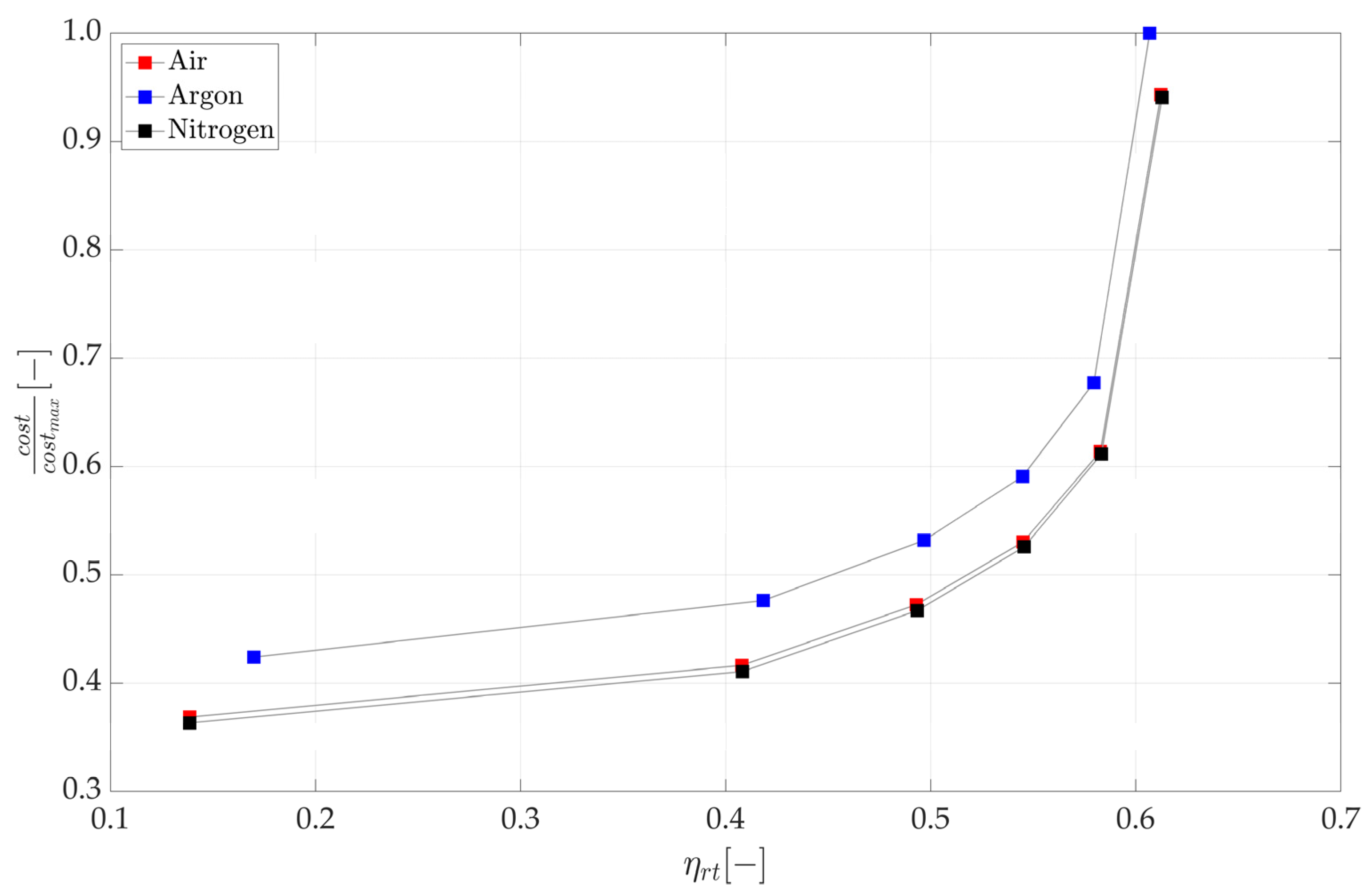
The first results deal with the Brayton cycle fluid selection for LBPTES and SBPTES and are reported in Figure 4 (LBPTES) and Figure 5 (SBPTES).
As far as the SBPTES is concerned, the results in Figure 4 convey three messages:
  • The roundtrip efficiency is almost independent of the cycle fluid, as in all cases the same maximum efficiencies can be achieved;
  • Using nitrogen led to a systematically cheaper system than argon and air;
  • However, the cost difference between the systems operating with nitrogen and air was minimal and within the cost correlation error band, which can be as high as ±30% in some cases [42].
The first bullet point is somewhat expected, as previous studies demonstrated that the PTES theoretical roundtrip efficiency depends not on the operating fluid but only on the operating temperatures [28]. A similar result was confirmed in the simulations, since the system can adjust the operating pressure ratios to achieve the same temperatures with all of the tested fluids, achieving similar roundtrip efficiencies.
As for the second and third bullet points, although using pure nitrogen would lower the system cost, compared to air and argon, the economic advantages over air seem minimal. If air and nitrogen are practically equivalent from an economic perspective, other effects should be factored into the cycle fluid selection. In particular, even though the operating fluid cost is not explicitly considered in the cost model in Appendix A, air is undoubtedly the cheapest option. Furthermore, its use would significantly simplify the system operation and maintenance, as any leakage and external air infiltration would entail almost no consequences. Finally, using air could simplify the design and sourcing of turbomachines. This aspect may have a significant economic impact, especially on the first PTES implementations, which may economically suffer from having to use purposely designed turbomachines. This effect is not captured in the cost model, which assumes the mass production of turbomachines and may have limited validity for first-of-a-kind systems. For all of the listed reasons, it is clear that using air instead of nitrogen brings numerous benefits that are challenging to quantify in a simulation but surely relevant once the economic assessments suggest that the fluids are almost equivalent. Therefore, air was used for the LBPTES systems in the rest of the paper.
Figure 4 shows the trade-off between the roundtrip efficiency and system cost. As a result, increasing the efficiency from approximately 0.15 to 0.4 had a limited impact on the cost. From efficiencies of approximately 0.4 to 0.58, any further efficiency increment could be achieved only for a significant increment of the equipment cost, which may increase up to approximately 50% of its initial value. Finally, the relatively limited efficiency improvement from 0.58 to approximately 0.61 entailed a further cost increment of approximately 60%. In total, the system cost would be more than doubled by increasing the roundtrip efficiency from 0.4 to more than 0.6.
In conclusion, the results shown in Figure 4 suggest that roundtrip efficiencies equal to and beyond 0.6 are not realistic for LBPTES: they might be technically feasible but almost certainly not cost effective. Slightly lower values (ηrt ≈ 0.58) could be worth achieving from an economic standpoint and should be considered to be representative of a more realistic estimation of LBPTES performance.
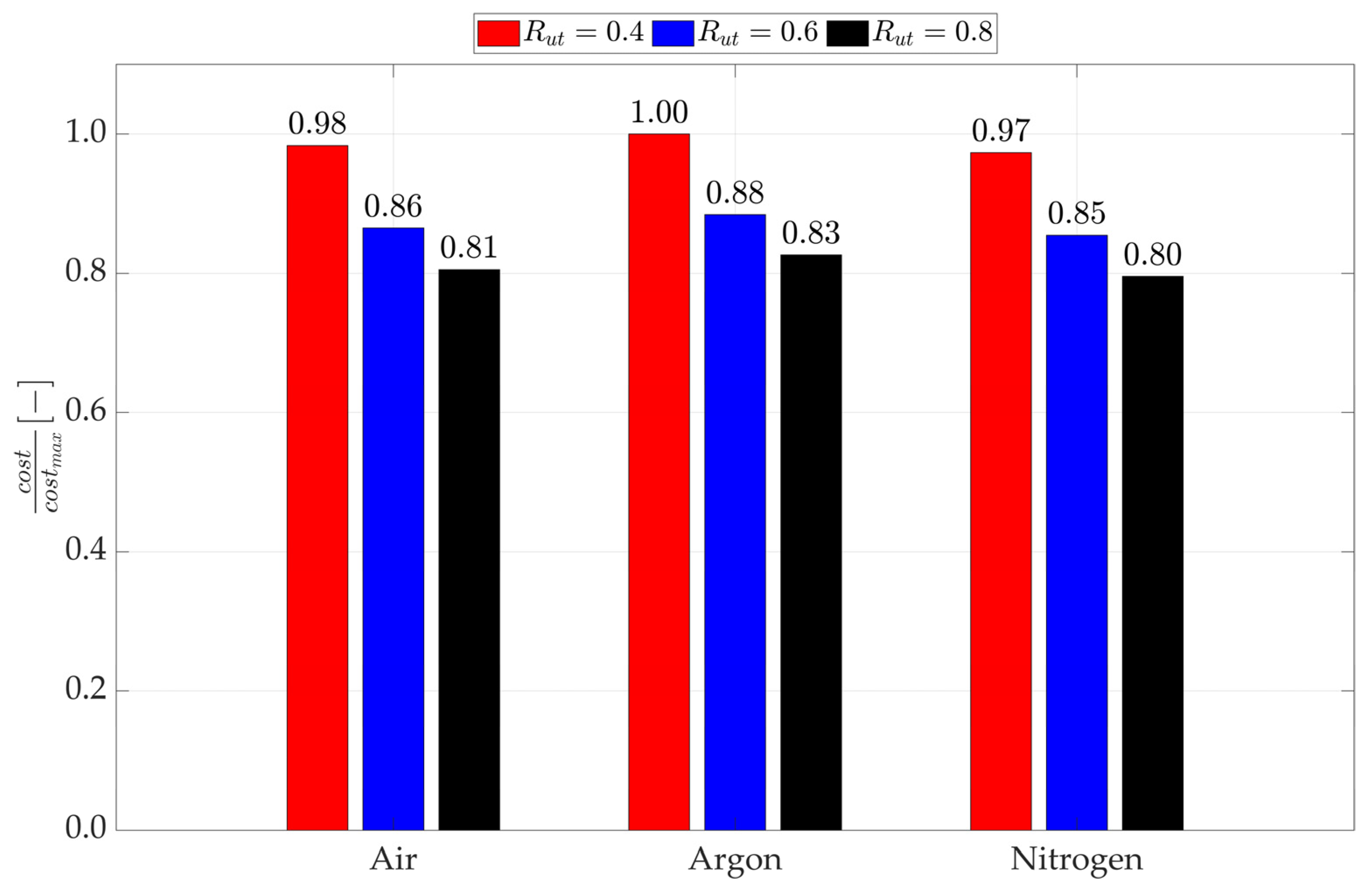
As for SBPTES, the results in Figure 5 suggest that similar conclusions to those discussed for LBPTES can be applied. In this case, the multi-objective design was not meaningful, as explained in Section 3.3, and a single configuration resulted from the design optimisation, as opposed to the Pareto fronts of LBPTES. Analogous to what was found for LBPTES, in Figure 5, the cost difference between the cycle fluids was relatively small so that air can be selected over nitrogen and argon without any significant penalty.
In addition to the direct economic implications reported in Figure 5, it is worth noting that the positive effects previously discussed for LBPTES of using air over nitrogen and argon were even more significant for SBPTES. In this case, a large gas volume was required to fill the packed beds, and the system was more exposed to leakages and infiltrations.
In Figure 5, all of the reported cases were characterised by a similar roundtrip efficiency (ηrt ≈ 0.58 for all the fluids), which was because, for SBPTES, analogous to LBPTES, the efficiency depends mostly on the operating temperatures. For SBPTES, a roundtrip efficiency ηrt ≈ 0.58 stemmed from the operating parameters listed in Section 3.4.
As a preliminary conclusion, the economic analysis discussed in this section suggests that air and not argon, as often proposed in the literature (e.g., in [10,13]), should be used as the Brayton cycle fluid in both LBPTES and SBPTES systems. This is because even though cheaper alternatives are available (e.g., nitrogen), the cost difference with air would be so small that the potentially increased plant complexity is not justified.
The cost difference between air, argon and nitrogen can be easily understood from the results in Figure 6, where the cost break down for SBPTES is shown in panel (a) and for LBPTES in panel (b). As a result, in both cases, the primary driver in the economic comparison was the turbomachines’ cost, while the heat exchangers played a minor role in LBPTES. As for the TES material and containers, these cost items were only marginally affected by the cycle operating fluid.
As per the cost models presented in Appendix A, the machines’ cost is essentially influenced by the pressure ratios and the mass flow rates, which vary with the Brayton cycle operating fluids. In Table 4, the charging and discharging cycle operating conditions are reported to support the discussion of the results in Figure 6. As can be noted, in addition to the comparison between SBPTES and LBPTES, as detailed in Section 4.2, it resulted that argon, compared to air and nitrogen, always operate with lower pressure ratios, which tend to lower the machines’ cost, but with much larger mass flow rates, which has the opposite effect. The mass flow rate cost impact prevails in this range of machine operating conditions, making argon the least cost-effective solution despite the lower operating pressures. The impact of the operating pressures can be seen in Figure 6a for SBPTES, as they weakly influence the cost of the TES containers. A similar effect was not even visible for LBPTES, as the pressure impact on the heat exchanger cost was negligible in this range of operating conditions. Of course, both of the results in Figure 6 and Table 4 confirm the slight difference in the cost between air and nitrogen in Figure 5, which reflects the marginally different pressure ratios and mass flow rates that characterise the cycles operating with the two fluids.

4.2. Comparison between LBPTES and SBPTES

After the most suited operating fluid (i.e., air) has been selected for both LBPTES and SBPTES, the two technologies can be compared.
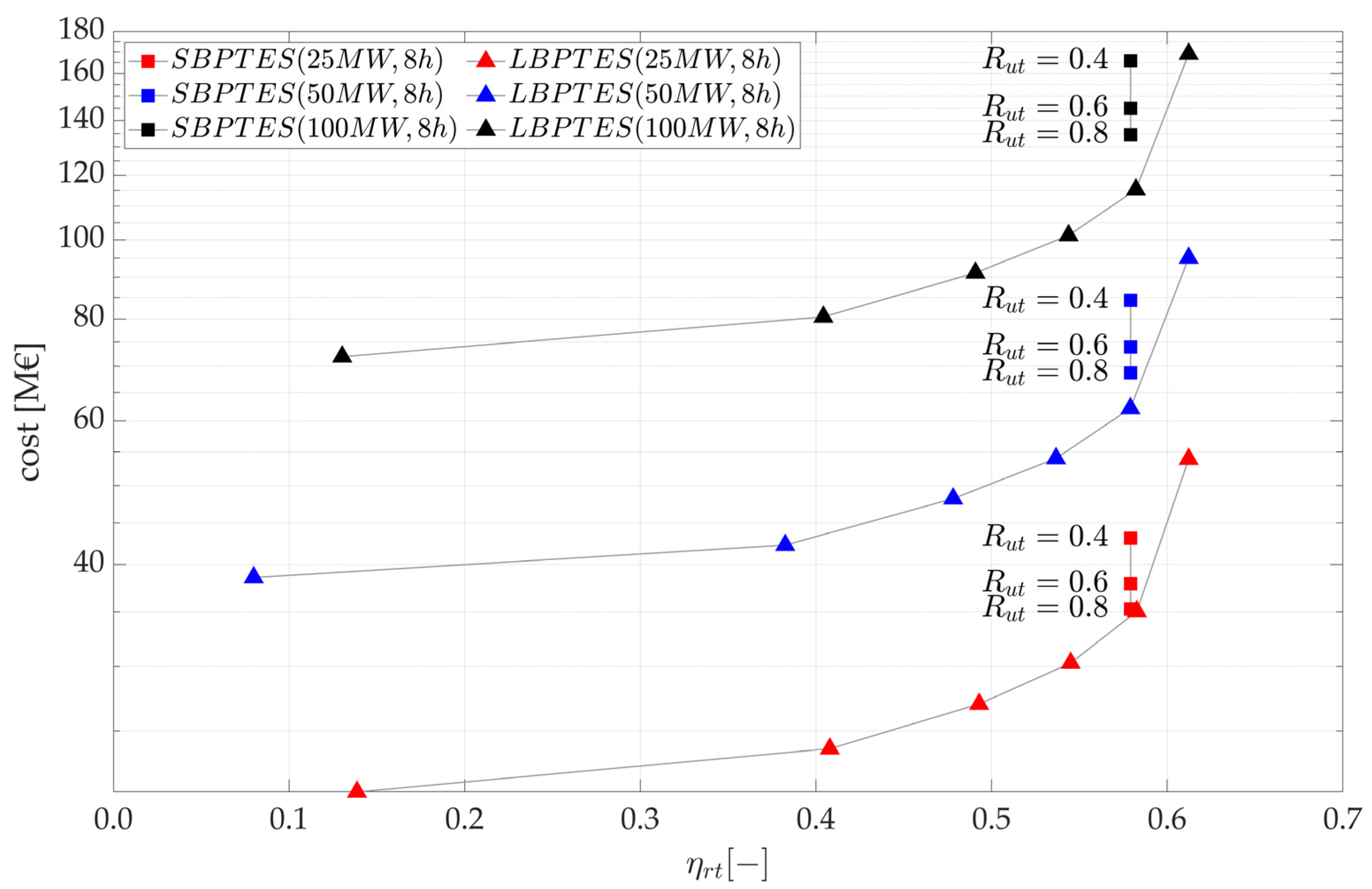
In Figure 7, LBPTES and SBPTES systems operating with air are compared for three nominal power inputs/outputs (25, 50 and 100 MW) and a nominal charge duration of 8 h. For the SBPTES, three values of Rut were considered, which had no impact on the cycle efficiency but affected the cost.
As a result, LBPTES systematically outperformed SBPTES not only concerning the maximum achievable efficiency but also according to the system cost. It is interesting to notice that SBPTES, under the design assumptions of Section 3.4, achieved a roundtrip efficiency ηrt ≈ 0.58, similar to that identified in Section 4.1 as the largest value of LBPTES roundtrip efficiency, still potentially cost effective.
Therefore, the main result of Figure 7 is:
  • LBPTES and SBPTES systems were practically equivalent, as far as the roundtrip efficiency was concerned, and realistic (i.e., potentially cost effective) configurations were considered instead of maximum efficiency ones;
The other observations stemming from Figure 7 are as follows:
  • LBPTES can achieve the same roundtrip efficiency as the SBPTES for a lower cost, and the cost gap between the technologies widens as the size of systems increases;
  • Configurations with high capacity utilisation ratios (Rut ≥ 0.8) are mandatory to make SBPTES competitive with LBPTES of similar sizes, which means that strategies aimed at improving the packed-bed utilisation are likely to be the standard if SBPTES becomes widespread.
It is worth noticing that while the techno-economic comparison here spanned from 25 to 100 MW, even lower charging/discharging rates can be envisioned for utilisations in smart grids or behind-the-meter industrial applications. In this range (10–25 MW), SBPTES could be more advantageous than LBPTES, especially for Rut ≥ 0.8. This may be relevant for the widespread use of these technologies and traces a possible roadmap for deploying the BPTES technology. In short, the first utility-scale pilots (e.g., demonstrators in a relevant environment likely to have a charging/discharging rate lower than 25 MW) could be based on SBPTES, while after the technology has been proven in the field, LBPTES could be used for larger applications, such as stand-alone and grid-connected plants.
Finally, the third bullet point directly impacts the SBPTES design. Nonstandard packed beds must be used to achieve Rut ≥ 0.8, such as partitioned [16] or segmented beds [37], which would prevent undesired thermal front propagations in the bed, increasing the usable bed capacity. As already pointed out, while the impact of such measures may increase SBPTES’s competitiveness, the additional cost related to these capacity-enhancing measures is unclear. Whatever the additional costs, the results shown in Figure 7 suggest that any Rut increment can save millions on a large SBPTES plant by reducing the TES materials but also the volume of pressurised vessels. In this regard, going back to Figure 5, it is possible to see how increasing Rut from 0.4 to 0.8 can reduce the plant’s cost by approximately 20%, which makes the bed segmentation and partition strategies very promising.
The results in Figure 7 are somewhat unexpected. Based only on the basic knowledge of LBPTES and SBPTES, it would be easy to conclude that SBPTES should be cheaper than LBPTES, given the absence of heat exchangers. However, Figure 7 suggests the opposite, and to understand why, it is necessary to investigate the SBPTES cost composition in more detail. This is shown in Figure 8, where the pieces of equipment were grouped to distinguish the impact of different sections. The energy-related costs (i.e., materials, tanks and vessels) were normalised for the stored energy in MWh ( W ˙ n e t , c h τ c h ), while the power-related costs (i.e., machines, heat exchangers, motor and generators) were normalized with the nominal charging/discharging ratings in MW.
From Figure 8, the following results can be found:
  • LBPTES had a significantly lower cost per MWh than SBPTES. Even for Rut = 0.8, the SBPTES cost per MWh was almost double the LBPTES;
  • The heat exchangers did not significantly penalise LBPTES, which achieved costs per MW similar to SBPTES. A clear cost advantage of SBPTES over LBPTES was visible only for limited power ratings ( W ˙ n e t , c h = 25 MW), whereas for large plants ( W ˙ n e t , c h ≥ 50 MW), LBPTES would be the cheapest alternative.
Figure 8 sheds some light on why SBPTES is not cheaper than LBPTES as expected, based on its simpler layout and fewer components. The fundamental difference between the two technologies is in the TES cost (EUR/kWh), which penalises the SBPTES, even though it uses cheaper materials than LBPTES. This is because the TES cost accounts for both materials and containers of hot and cold reservoirs, and while the firsts are cheaper in SBPTES, even when Rut is considered, the seconds are pressurised in SBPTES, thus much costlier, whereas LBPTES only employs cheaper atmospheric tanks. This originates a substantial cost difference, as the final TES cost for LBPTES, considering materials and containers, is approximately 50% of what resulted for SBPTES, according to the results in Figure 9.
Lower values of Rut exacerbate the difference in cost per kWh. Figure 8a shows that LBPTES may achieve a cost per kWh of approximately 50% of SBPTES only when Rut is equal to or higher than 0.8. This means that, without introducing any measure to partition the packed beds in SBPTES, which allows for increasing Rut, the SBPTES economic outlook is very negative compared to LBPTES, and the resulting cost per kWh can be up to four times higher.
As for the cost per MW (Figure 8b), it must be considered that it includes turbomachines and heat exchangers and, thus, if the SBPTES cost per MW is similar to the LBPTES, despite not using heat exchangers, it means that turbomachines must be much costlier in SBPTES than in LBPTES (as it will be discussed in detail for Figure 9). This effect can be appreciated in the analysis thanks to the used machine cost models that account for pressure ratios and mass flow rates, which vary significantly between LBPTES and SBPTES (see Appendix A for more details on the machine cost models).
The cost breakdown in Figure 9 is related to a configuration with W ˙ n e t , c h = 50 MW, τch = 8 h, and for SBPTES, Rut = 0.8; this suggests that the summed cost of the heat exchangers and machines was practically the same for LBPTES and SBPTES, which confirms the results in Figure 8b, showing that the specific cost per kW was similar for SBPTES and LBPTES for W ˙ n e t , c h = 50 MW.
Based on the cost models in Appendix A and remembering that the plant nominal charging/discharging rates are linear with the cycle mass flow rates m ˙ , for the same cycle temperatures (i.e., specific work), it can be understood that the cost of the heat exchangers and turbomachinery scales differently with the plant size. The cost of the heat exchangers, C H E X , does not scale linearly with the plant size or the cycle mass flow rate, as it follows from C H E X ( U A ) n ( m ˙ ) n , with n < 1 and U A being the heat exchanger conductance in W/K (Equation (A6)). Instead, the cost of the turbomachines, C t u r b / c o m p , is linear with the plant nominal power rating and, thus, with m ˙ , i.e., C t u r b / c o m p m ˙ (Equations (A1) and (A2)). Therefore, the relative impact of the machines on the total cost per MW increases with the plant’s nominal power rating. This penalises SBPTES, for which the machines represent the most significant cost share (Figure 9), as the plant size increases and explains the trends observed in Figure 8b for the specific costs of the two technologies. In summary, a linear dependency of the cost on the power rating, dictated by the relative impact of the turbomachines, means that the SBPTES cost per kW in Figure 8b tends to flatten, stabilising over a constant value. In contrast, for LBPTES, the cost per kW decreases with the nominal rating, as it depends on both the turbomachinery and heat exchangers, whose specific cost decreases with the plant charging and discharging rates.
An example of the different operating conditions between SBPTES and LBPTES can be found in Table 5, where the operating mass flow rates and pressure ratios for the case with 50 MW, 8 h was reported. As a result, LBPTES generally has larger mass flow rates, which increase the cost of the machines linearly but significantly lower pressure ratios β (-), which are the main cost drivers, in relative terms, since the cost depends on β∙ln(β) [43], which grows faster than a linear relation. For this reason, SBPTES machines cost significantly more than LBPTES ones, which counterbalances the potential savings over LBPTES due to the absence of heat exchangers.
The previous considerations are valid for systems of any size but can be directly verified for a specific case ( W ˙ n e t , c h = 50 MW, τch = 8 h, Rut = 0.8) in Figure 9. As expected, the heat exchangers represented a major share of the LBPTES cost and were nearly absent in SBPTES. However, the cost of the SBPTES machines was double the cost of the LBPTES machines and balanced the heat exchanger absence.
As for the TES cost, SBPTES indeed uses inexpensive materials compared to LBPTES. However, the material represents only a minor share of SBPTES cost per MWh, while the vast majority is represented by the pressurised vessels. This resulted in being more than three times costlier than the LBPTES atmospheric tanks, overcoming the economic advantages of using cheap materials.

4.3. Policy Implications

This section provides a brief overview of the policy implications stemming from the results in Section 4.1 and Section 4.2.
From a policy point of view, for storage technology, not only is the cost important, but also a set of additional features, including roundtrip efficiency, ramp rates, self-discharge and reliability, that comes with the controllability and stability of power input and output, and the use of critical raw materials. Based also on the discussion in Section 2.3, it is easy to understand that SBPTES and LBPTES are similar in what concerns most of the noneconomic features. In particular, the results in Section 4.2 show that they have comparable roundtrip efficiencies. Furthermore, since similar pieces of equipment characterise the two systems, they may achieve comparable ramp rates. In this regard, SBPTES do not use extensive heat transfer equipment, which should enable the system to start up faster, especially after long idle periods. For both technologies, start-up times between ten and twenty minutes can be assumed based on what can be achieved by similar storage technologies such as CAES [44,45] and LAES [46].
Even though SBPTES and LBPTES use different materials, these are safe and widely available materials, unlikely to be subject to supply chain disruption, unlike critical raw materials.
Both systems are reliable and controllable. Section 2.3 shows how the LBPTES may be more straightforward to regulate, while the SBPTES may experience variation in power input/outputs due to the packed-bed thermal behaviour. Advanced packed bed configurations may allow the SBPTES to operate stably, solving this issue [16].
Since LBPTES and SBPTES are similar from several angles, the system cost becomes the decisive factor in discerning the most suited for deployment on the energy grids. The results in Section 4.2 indicate pretty clearly that LBPTES should be preferred for large-scale applications, while SBPTES requires technological improvements (particularly regarding the use of partitioned packed beds) to be comparable. Even in this case, a clear advantage over LBPTES could be achieved only for small-scale applications (less than 25 MW) and short durations.
Going beyond the comparison against solid-based systems, LBPTES can be compared to different storage technologies aimed at similar scales and durations. This can be done according to the data provided by a recent techno-economic assessment from the US Department of Energy (DOE) for CAES and PHES [45]. In the range of 100 MW and for durations between 4 and 8 h, the PHES cost per kWh is approximately 70 EUR/kWh, more than three times larger than the LBPTES costs in Figure 7 and Figure 8a. Of course, the DOE’s estimation includes a number of ancillary costs (such as installation, engineering and insurance) not included in the present analysis. However, these costs usually amount to no more than 50% of the bare equipment costs [18] (i.e., those in Figure 8a), which makes LBPTES a viable alternative for long-duration applications. For what concerns the cost per kW, the comparison with PHES was less favourable. PHES is characterised by a cost of approximately 1060 EUR/kW, similar to what is reported in Figure 8b for LBPTES. However, a factor between 1.1 and 1.5 should be multiplied by the numbers in Figure 8b, making the LBPTES cost from approximately 1100 to 1500 EUR/kW and be less viable than PHES.
Compared to CAES, the comparison was slightly worse: LBPTES may achieve a similar cost per kW, which for CAES was approximately 1100 EUR/kW, but a much higher cost per kWh, which was extremely low for CAES, approximately 3 EUR/kWh [45].
Even though LBPTES may achieve a slightly worse economic performance than CAES and PHES, it is worth noting that it has some strategic advantages compared to both. LBPTES has no geographical constraints, while the widespread availability of suitable sites for CAES and PHES is often questioned [9]. Furthermore, compared to CAES, LBPTES does not rely on fossil fuels, a significant advantage in promoting electric power decarbonisation.
In conclusion, given the considerations above and the results in Figure 8, it can be concluded that LBPTES may compete with the leading storage technologies for large-scale and long-duration applications, potentially surpassing them in those cases where favourable geographical conditions are absent. This is relevant because it suggests that it is possible to deploy large-scale storage for long-duration applications without geographical constraints and with no sizeable economic penalisation compared to the more affirmed alternatives.

5. Conclusions

The cost and the roundtrip efficiency achievable by SBPTES and LBPTES systems were calculated and compared in an analysis. For LBPTES, the system was designed through a multi-objective optimisation which yielded the optimal trade-off (Pareto front) between the cost and roundtrip efficiency. The same procedure could not be followed for SBPTES, as explained in Section 3.3, for which a unique configuration could be found once some operating parameters were fixed.
The techno-economic analysis led to the following conclusions:
  • Air should be used as operating fluid in both LBPTES and SBPTES systems. The nitrogen configurations were the cheapest, but the cost difference between this fluid and air was approximately 1–2 percentage points for both SBPTES and LBPTES. With such limited differences, there are no real economic advantages over air, which is inexpensive and less prone to infiltration or leakages. Using argon led to costlier systems. The cost difference between aragon and air was approximately 3% for SBPTES, while it was between 4% and 7% for LBPTES. Therefore, argon should be avoided;
  • For roundtrip efficiencies up to up ηrt = 0.58, LBPTES was always cheaper than SBPTES for any size over 25 MW/8 h. LBPTES can achieve higher efficiencies, up to approximately 0.61, but any increment over 0.58 is most likely not cost effective: for a 5% efficiency increment, from 0.58 to 0.61, the cost would increase up to approximately 35%. The situation is the opposite for systems with smaller nominal power ratings and charging durations, and SBPTES could be a cheaper alternative to LBPTES;
  • SBPTES was costlier than LBPTES, despite using cheaper TES materials and fewer components for two reasons:
  • The materials represent only a minor share of the total cost, less than 1% in SBPTES and approximately 7% in LBPTES. The cost of the containers always dominated the TES cost, accounting for over 60% in LBPTES and 90% in SBPTES. In the case of SBPTES, pressurised vessels must be used instead of atmospheric tanks, which results in a much higher cost;
  • SBPTES operates with larger pressure ratios than LBPTES, which makes its turbomachines costlier. LBPTES is based on a recuperated cycle, which achieves the same efficiency for a lower pressure ratio. Machines accounted for over 70% of total cost in SBPTES and 31% in LBPTES;
  • The cost difference between LBPTES and SBPTES increases with the nominal power rating. This is because of the cost of machines are linear with the size, which impacts more on SBPTES than on LBPTES. For large power ratings (over 50 MW), the LBPTES cost per kW is lower than for SBPTES, since the cost of the heat exchangers, representing more than 50% of the total, increases less than that of the machines.
In summary, the presented study suggests that LBPTES represents a cheaper and more efficient alternative to SBPTES and should be preferred for large-scale applications with a power rating in the tens of MW and beyond. For smaller applications (i.e., rated power below 10 MW), SBPTES could be preferred. This is because the LBPTES significantly benefits from an economy of scale at larger sizes. Instead, the heat exchangers’ specific cost is particularly penalising at lower scales, leading to a very high cost per installed kW.

Author Contributions

Conceptualisation, G.F.F.; methodology, G.F.F.; software, G.F.F.; formal analysis, G.F.F.; investigation, G.F.F.; resources, L.F. and U.D.; writing—original draft preparation, G.F.F.; writing—review and editing, L.F. and U.D.; visualisation, G.F.F.; supervision, L.F. and U.D.; project administration, L.F. and U.D.; funding acquisition, L.F. and U.D. All authors have read and agreed to the published version of the manuscript.

Funding

This research was partially funded by the Italian Ministry of University and Research (MUR) as part of the PON 2014-2020 “Research and Innovation” resources—Green/Innovation Action—DM MUR 1062/2022.

Data Availability Statement

Data are available upon request to the corresponding author.

Conflicts of Interest

The authors declare no conflict of interest. The funders had no role in the design of the study; in the collection, analyses, or interpretation of data; in the writing of the manuscript; or in the decision to publish the results.

Appendix A

This section reports the costing correlations used for the SBPTES and LBPTES systems. SBPTES and LBPTES share the correlations used for turbomachines, motors, generators and air coolers. For the turbine, the correlation from [43] is used (Equation (A1)):
C t u r = 1.051 266.3 m ˙ 0.94 η i s β ln ( β )
where m ˙ is the machine mass flow rate, ηis is the machine isentropic efficiency and β is the machine pressure ratio. For the compressor, a similar correlation from [43] is used (Equation (A2)):
C c m p = f m 1.051 39.5 m ˙ 0.90 η i s β ln ( β )
The parameter fm was not presented in the original correlation, which was developed for standard Brayton cycles. However, the compressor operating temperatures in SBPTES are higher than standard ones, as the outlet temperature may achieve 500 to 600 °C in the charging cycle. Therefore, suitable construction materials (i.e., stainless steel) must be used. fm = 1 (carbon steel) for the discharging cycle, as the compressor operates in a standard temperature range. Instead, fm = 2 (stainless steel) for the charging cycle, as stainless-steel compressors cost two times that of carbon steel ones, as suggested in [47].
For electric motors and generators, the following correlations [48] are used (Equations (A3) and (A4)):
C m o t = 399,400 ( W ˙ m o t 1 e 3 ) 0.61
C g e n = 108,900 ( W ˙ g e n 1 e 3 ) 0.55
where W ˙ m o t is the motor power input in kW, and W ˙ g e n is the generator power output in kW.
Finally, for air coolers, the following correlation [48] is used (Equation (A5)):
C c o o l = 32.88 ( U A c o o l ) 0.75
where UAcool is the cooler overall conductance in W/K.
The correlations in Equations (A1) and (A2) account for the pressure ratio and mass flow rate impact, which allow for comparing different working fluids. Such correlations are derived from actual gas turbine cost data [43] and are valid for temperature and pressure ranges similar to those investigated here. See, for example, [49]. Although the correlations could be considered outdated, they have been used in recent years, see [50,51,52], and were considered valid for the present analysis. Finally, the correlations were used to compare SBPTES and LBPTES on common ground. Therefore, the impact of any uncertainty upon the predicted final cost is somehow mitigated because only relative values were considered.
Specific to LBPTES is the cost correlation used for the heat transfer equipment. For both gas–liquid and gas–gas heat exchangers, the correlation in [48] was used (Equation (A6)), which includes printed circuit heat exchangers (PCHEs), a technology suited for gas–liquid heat transfer, also involving molten salts [53,54].
C h o t / c o l d / r e g = 49.45 ( U A h o t / c o l d / r e g ) 0.75
where UAhot/cold/reg may represent the thermal conductance in W/K of the hot reservoir, cold reservoir or regenerator heat exchanger.
For the TES cost, different materials and containers are considered for SBPTES and LBPTES.
For the SBPTES, pressurised vessels are used. The vessel cost correlation [55], which is valid for horizontal vessels with a diameter of 4 m, is as follows (Equation (A7)):
C v e s s e l = f m f p ( 2436 L v e s s e l + 5916 )
where fm = 1 is for carbon steel (cold reservoir), and fm = 3 is for stainless steel (hot reservoir); fp = 1.6 is for operating pressures lower than 10 bar (cold reservoir), and fp = 3.2 is for operating pressures lower than 50 bar (hot reservoir); Lvessel is the vessel length, calculated from the vessel volume Vvessel in m3 by assuming a diameter equal to 4 m.
For LBPTES, atmospheric tanks are used. The cost correlation is from [55] (Equation (A8)):
C t a n k = f m ( 170.5 V t a n k + 59 , 560 )
where fm = 1 is for stainless steel, and it is valid for both hot and cold reservoirs; Vtank is the tank volume in m3.
Finally, for the TES materials, a constant cost per kg is assumed (Equation (A9)):
C m a t = γ M m a t
where γ is the specific cost per kg. γ = 0.61 $/kg for the Hexane (LBPTES cold reservoir) [10]; γ = 0.54 $/kg for the salor salts (LBPTES hot reservoir) [10,56]; finally, γ = 0.02 $/kg for the limestone [34].

Appendix B

Here the calculations required for evaluating the quantities in Equations (1)–(3) and the cost model are reported.
The charging and discharging exergy efficiency in Equations (2) and (3) are calculated through the following equations. Equations (A10)–(A13) define the hot and cold reservoir exergy contributions based on the Brayton cycles in Figure 3. For the LBPTES, Equations (A10) and (A11) are used:
ϕ c h = E x h o t + E x c o l d E c h = m ˙ h o t [ h h o t , 2 h h o t , 1 T 0 ( s h o t , 2 s h o t , 1 ) ] + m ˙ c o l d [ h c o l d , 2 h c o l d , 1 T 0 ( s c o l d , 2 s c o l d , 1 ) ] m ˙ c h [ h c h , 1 h c h , 2 ( h c h , 5 h c h , 4 ) ] / η e l
ϕ d = E d E x h o t + E x c o l d = m ˙ d [ h d , 1 h d , 2 ( h d , 5 h d , 4 ) ] η e l m ˙ h o t [ h h o t , 2 h h o t , 1 T 0 ( s h o t , 2 s h o t , 1 ) ] + m ˙ c o l d [ h c o l d , 2 h c o l d , 1 T 0 ( s c o l d , 2 s c o l d , 1 ) ]
where m ˙ h o t , m ˙ c o l d , m ˙ c h and m ˙ d are the mass flow rates in kg/s circulating in the hot and cold reservoirs and in the charging and discharging cycles, respectively; T0 is the reference (ambient) temperature in K; h() and s() are the fluid enthalpies (J/kg) and entropies (J/kgK−1); finally, ηel is the motor/generator electromechanical efficiency. The mass flow rates in Equations (A10) and (A11) can be easily calculated from the component energy balance once a nominal power rating for input and output has been decided.
As for the SBPTES, Equations (A12) and (A13) hold:
ϕ c h = E x h o t + E x c o l d E c h = h c h , 1 h c h , 4 T 0 ( s c h , 1 s c h , 4 ) + h c h , 2 h c h , 3 T 0 ( s c h , 2 s c h , 3 ) [ h c h , 1 h c h , 2 ( h c h , 4 h c h , 3 ) ] / η e l
ϕ d = E d E x h o t + E x c o l d = h d , 1 h d , 5 T 0 ( s d , 1 s d , 5 ) + h d , 2 h d , 3 T 0 ( s d , 2 s d , 3 ) [ h d , 1 h d , 2 ( h d , 4 h d , 3 ) ] η e l
Differently from LBPTES, in SBPTES, there are no exergetic losses due to the heat transfer between TES material and the cycle operating fluid. In practice, minimal losses are present due to the finite temperature differences in the packed bed. However, they are assumed to be small compared to those occurring in the cycle and, therefore, neglected.
The relevant quantities for the LBPTES and SBPTES cost models are the heat exchanger UA, required materials and the related TES volume.
For the i-th heat exchanger, UA is calculated as in Equation (A14):
U A i = Q ˙ i f i L M T D i
where Qi is the heat flow rate, fi is the correction compared to the ideal counterflow arrangement and LMTDi is the mean log temperature difference. fi is equal to 0.8 for the air cooler and equal to 0.95 for the other heat exchangers.
As for the mass of TES materials, for LBPTES, Mhot and Mcold in kg are calculated in Equations (A15) and (A16):
M h o t = m ˙ h o t τ c h = m ˙ c h ( h c h , 1 h c h , 6 ) ( h h o t , 1 h h o t , 2 ) τ c h
M c o l d = m ˙ c o l d τ c h = m ˙ c h ( h c h , 3 h c h , 4 ) ( h c o l d , 1 h c o l d , 2 ) τ c h
For the SBPTES, Equations (A17) and (A18) are used:
M h o t , i d = Q ˙ h o t c p ¯ h o t ( T c h , 1 T c h , 4 ) τ c h = m ˙ c h ( h c h , 1 h c h , 4 ) [ h c h , 1 h c h , 2 ( h c h , 4 h c h , 3 ) ] 1 c p ¯ h o t ( T c h , 1 T c h , 4 ) τ c h
M c o l d , i d = Q ˙ c o l d c p ¯ c o l d ( T c h , 2 T c h , 3 ) τ c h = m ˙ c h ( h c h , 2 h c h , 3 ) [ h c h , 1 h c h , 2 ( h c h , 4 h c h , 3 ) ] 1 c p ¯ c o l d ( T c h , 2 T c h , 3 ) τ c h
where c p ¯ h o t and c p ¯ c o l d are the average cp in J/kg between the hot and cold reservoir extreme temperatures.
The masses calculated from Equations (A17) and (A18) are ideal values, valid if the whole available material can be used. However, as explained in Section 2.2, a significant share of SBPTES nominal capacity cannot be used if high roundtrip efficiency is desired [35]. Therefore, larger masses than those predicted in Equations (A17) and (A18) are required for achieving the desired capacity. Investigating the actual trade-off between usable capacity and roundtrip efficiency was beyond the scope of this paper, as many factors should be considered, among which include the packed-bed material and granulometry as well as the charging and discharging durations. In this paper, a simple utilisation ratio factor, Rut, ranging from 0.4 to 0.8 [35], was considered to account for the unused capacity. Therefore, Equations (A19) and (A20) must be used for SBPTES:
M h o t = M h o t , i d R u t
M c o l d = M c o l d , i d R u t
Finally, the TES volumes Vhot and Vcold are calculated from Mhot and Mcold. For the LBPTES, Equation (A21) holds:
V h o t / c o l d = M h o t / c o l d ρ h o t / c o l d
where ρhot/cold is the density in kg/m3 of hot and cold reservoir materials. As for the SBPTES, Equation (A21) must be corrected to account for the packed-bed porosity as in Equation (A22):
V h o t / c o l d = M h o t / c o l d ρ h o t / c o l d ( 1 α )
where α = 0.4 is the TES void ratio, i.e., the ratio between void volume and total packed bed volume [35].

Appendix C

In this section, the constraints for the problem in Equation (5) are stated for the LBPTES and SBPTES systems. In both cases, the constraint set encompasses all the constitutive equations needed to ensure that the optimisation problem yields a sound design from a physical and engineering point of view. Such equations represent, directly or indirectly, mass and energy balance on each component, adiabatic compression and expansion relations, and minimum temperature difference in the heat exchangers.
For the LBPTES, the set of constraints is reported in Equations (A23)–(A41), for the charging and discharging phase, respectively:
η i s , c m p = 1 ( β c h ) k 1 k   / 1 T c h , 1 T c h , 2
η i s , t u r = 1 T c h , 4 T c h , 5   / 1 ( β c h ) 1 k k
h c h , 2 h c h , 3 = h c h , 6 h c h , 5
T c h , 1 T h o t , 1 + p p h o t
T c h , 6 T h o t , 2 + p p h o t
T c h , 4 T c o l d , 2 p p c o l d
T c h , 3 T c o l d , 1 p p c o l d
T c h , 6 T c h , 2 + p p r e g
T c h , 5 T c h , 3 + p p r e g
T c h , 1 T m a x , c m p
Equations (A23) and (A24) are the equations for adiabatic compression and expansion, with ηis,cmp/tur being the compressor and turbine isentropic efficiency; Equation (A25) is the heat balance on the charging cycle regenerator; Equations (A26)–(A31) enforce pinch points (pphot/cold/reg) observance in the heat exchangers. As reported in Figure 1 and Figure 2, Thot/cold,1 and Thot/cold,2 represent the hot and cold reservoir operating temperatures. Finally, Equation (A32) limits the compressor discharge temperature to a maximum value due to technological limits. Modern aero-derivative turbine compressors may achieve a discharge temperature around 600 °C, which should be considered the current technology limitation for such components.
As for the discharging cycle:
η i s , c m p = 1 ( β d ) k 1 k   / 1 T d , 5 T d , 4
η i s , t u r = 1 T d , 2 T d , 1   / 1 ( β d ) 1 k k
h d , 2 h d , 3 = h d 7 h d , 6
T d , 1 T h o t , 1 p p h o t
T d , 7 T h o t , 2 p p h o t
T d , 4 T c o l d , 2 + p p c o l d
T d , 3 T c o l d , 1 + p p c o l d
T d , 7 T d , 2 p p r e g
T d , 6 T d , 3 p p r e g
T d , 6 T e n v + p p c o o l
The previous equations have a similar meaning to the charging phase, except for Equation (A42), which deals with the Air cooler minimum allowable temperature difference.
For the SBPTES, the constraint set is reported in Equations (A43)–(A54), for the charging and the discharging phases, respectively.
η i s , c m p = 1 ( β c h ) k 1 k   / 1 T c h , 1 T c h , 2
η i s , t u r = 1 T c h , 4 T c h , 5   / 1 ( β c h ) 1 k k
T c h , 1 T h o t , 1 + p p h o t
T c h , 3 T c o l d , 1 p p c o l d
T c h , 1 T m a x , c m p
Equations (A43)–(A47) have the same meaning as discussed for the LBPTES system.
As for the discharging phase:
η i s , c m p = 1 ( β d ) k 1 k   / 1 T d , 4 T d , 3
η i s , t u r = 1 T d , 2 T d , 1   / 1 ( β d ) 1 k k
T d , 1 = T c h , 1 2 p p h o t
T d , 2 = T c h , 2 + 2 p p h o t
T d , 3 = T c h , 3 + 2 p p c o l d
T d , 5 = T c h , 4 2 p p c o l d
T d , 5 T e n v + p p c o o l
Equations (A48), (A49) and (A54) have a similar meaning to that discussed for the charging phase. Differently from what ocurrs for the LBPTES, in SBPTES the gas temperatures at the packed-bed inlet and outlet must be the same in the charging and discharging cycles (Equations (A50)–(A53)), apart from a slight temperature difference needed for the heat transfer. Such a constraint ensures that the system always operates between the same design temperatures.

References

  1. European Parliament and the Council of the European Union Renewable Energy Directive. Available online: https://ec.europa.eu/energy/topics/renewable-energy/renewable-energy-directive/overview_en (accessed on 6 April 2021).
  2. European Commission A European Green Deal. Available online: https://ec.europa.eu/info/strategy/priorities-2019-2024/european-green-deal_en#actions (accessed on 15 July 2021).
  3. Palizban, O.; Kauhaniemi, K. Energy storage systems in modern grids—Matrix of technologies and applications. J. Energy Storage 2016, 6, 248–259. [Google Scholar] [CrossRef]
  4. Zappa, W.; Junginger, M.; van den Broek, M. Is a 100% renewable European power system feasible by 2050? Appl. Energy 2019, 233–234, 1027–1050. [Google Scholar] [CrossRef]
  5. Argyrou, M.C.; Christodoulides, P.; Kalogirou, S.A. Energy storage for electricity generation and related processes: Technologies appraisal and grid scale applications. Renew. Sustain. Energy Rev. 2018, 94, 804–821. [Google Scholar] [CrossRef]
  6. Rogner, M.; Troja, N. The world’s water battery: Pumped hydropower storage and the clean energy transition. IHA Work. Pap. 2018, 1, 1–15. [Google Scholar]
  7. Dumont, O.; Frate, G.F.; Pillai, A.; Lecompte, S.; De paepe, M.; Lemort, V. Carnot battery technology: A state-of-the-art review. J. Energy Storage 2020, 32, 101756. [Google Scholar] [CrossRef]
  8. Bublitz, A.; Keles, D.; Zimmermann, F.; Fraunholz, C.; Fichtner, W. A survey on electricity market design: Insights from theory and real-world implementations of capacity remuneration mechanisms. Energy Econ. 2019, 80, 1059–1078. [Google Scholar] [CrossRef]
  9. Frate, G.F.; Ferrari, L.; Desideri, U. Energy storage for grid-scale applications: Technology review and economic feasibility analysis. Renew. Energy 2021, 163, 1754–1772. [Google Scholar] [CrossRef]
  10. Laughlin, R.B. Pumped thermal grid storage with heat exchange. J. Renew. Sustain. Energy 2017, 9, 044103. [Google Scholar] [CrossRef] [Green Version]
  11. Salomone-González, D.; González-Ayala, J.; Medina, A.; Roco, J.M.M.; Curto-Risso, P.L.; Calvo Hernández, A. Pumped heat energy storage with liquid media: Thermodynamic assessment by a Brayton-like model. Energy Convers. Manag. 2020, 226, 113540. [Google Scholar] [CrossRef]
  12. Zhao, Y.; Liu, M.; Song, J.; Wang, C.; Yan, J.; Markides, C.N. Advanced exergy analysis of a Joule-Brayton pumped thermal electricity storage system with liquid-phase storage. Energy Convers. Manag. 2021, 231, 113867. [Google Scholar] [CrossRef]
  13. Desrues, T.; Ruer, J.; Marty, P.; Fourmigué, J.F. A thermal energy storage process for large scale electric applications. Appl. Therm. Eng. 2010, 30, 425–432. [Google Scholar] [CrossRef]
  14. Zhang, H.; Wang, L.; Lin, X.; Chen, H. Combined cooling, heating, and power generation performance of pumped thermal electricity storage system based on Brayton cycle. Appl. Energy 2020, 278, 115607. [Google Scholar] [CrossRef]
  15. Wang, L.; Lin, X.; Chai, L.; Peng, L.; Yu, D.; Chen, H. Cyclic transient behavior of the Joule–Brayton based pumped heat electricity storage: Modeling and analysis. Renew. Sustain. Energy Rev. 2019, 111, 523–534. [Google Scholar] [CrossRef]
  16. Wang, L.; Lin, X.; Zhang, H.; Peng, L.; Chen, H. Brayton-cycle-based pumped heat electricity storage with innovative operation mode of thermal energy storage array. Appl. Energy 2021, 291, 116821. [Google Scholar] [CrossRef]
  17. Raj, A.; Philippe, L. Use of External Air for Closed Cycle Inventory Control. U.S. Patent 20180187627-A1, 28 December 2016. [Google Scholar]
  18. Mctigue, J.D.; Farres-antunez, P.; Markides, C.N.; White, A.J. Techno-economic analysis of recuperated Joule-Brayton pumped thermal energy storage. Energy Convers. Manag. 2022, 252, 115016. [Google Scholar] [CrossRef]
  19. Zhang, H.; Wang, L.; Lin, X.; Chen, H. Technical and economic analysis of Brayton-cycle-based pumped thermal electricity storage systems with direct and indirect thermal energy storage. Energy 2022, 239, 121966. [Google Scholar] [CrossRef]
  20. Kotas, T.J. Chapter 2: Basic Exergy Concepts. In The Exergy Method of Thermal Plant Analysis; Elsevier: Amsterdam, The Netherlands, 1985; pp. 29–56. ISBN 978-0-408-01350-5. [Google Scholar]
  21. Laughlin, R.B. Mass Grid Storage with Reversible Brayton Engines. In Thermal, Mechanical, and Hybrid Chemical Energy Storage Systems; Brun, K., Allison, T., Dennis, R., Eds.; Academic Press: Cambridge, MA, USA, 2021; pp. 27–59. ISBN 978-0-12-819892-6. [Google Scholar]
  22. Harris, P.; Wolf, T.; Kesseli, J.; Laughlin, R.B. An Investigation of Reversing Axial Turbomachinery for Thermal Energy Storage Application. In Proceedings of the Volume 5: Controls, Diagnostics, and Instrumentation, Cycle Innovations: Energy Storage, American Society of Mechanical Engineers, Virtual, Online, 21–25 September 2020. [Google Scholar]
  23. Chiapperi, J.D.; Greitzer, E.M.; Tan, C.S. Attributes of Bi-Directional Turbomachinery for Pumped Thermal Energy Storage. J. Turbomach. 2023, 145, 1–21. [Google Scholar] [CrossRef]
  24. Liang, T.; Vecchi, A.; Knobloch, K.; Sciacovelli, A.; Engelbrecht, K.; Li, Y.; Ding, Y. Key components for Carnot Battery: Technology review, technical barriers and selection criteria. Renew. Sustain. Energy Rev. 2022, 163, 112478. [Google Scholar] [CrossRef]
  25. Hamdy, S.; Morosuk, T.; Tsatsaronis, G. Exergetic and economic assessment of integrated cryogenic energy storage systems. Cryogenics 2019, 99, 39–50. [Google Scholar] [CrossRef]
  26. Malta, Thermo-Electric Energy Storage. Available online: https://www.maltainc.com/solution/ (accessed on 8 November 2022).
  27. Apte, R.; Philippe, L. Variable Pressure Inventory Control of Closed Cycle System with a High Pressure Tank and an Intermediate Pressure Tank; Malta Inc.: Cambridge, MA, USA, 2016. [Google Scholar]
  28. Steinmann, W.-D.; Jockenhöfer, H.; Bauer, D. Thermodynamic Analysis of High-Temperature Carnot Battery Concepts. Energy Technol. 2020, 8, 1900895. [Google Scholar] [CrossRef] [Green Version]
  29. Steinmann, W.D. Thermo-mechanical concepts for bulk energy storage. Renew. Sustain. Energy Rev. 2017, 75, 205–219. [Google Scholar] [CrossRef]
  30. Olympios, A.V.; McTigue, J.D.; Farres-Antunez, P.; Tafone, A.; Romagnoli, A.; Li, Y.; Ding, Y.; Steinmann, W.-D.; Wang, L.; Chen, H.; et al. Progress and prospects of thermo-mechanical energy storage—A critical review. Prog. Energy 2021, 3, 022001. [Google Scholar] [CrossRef]
  31. Benato, A.; Stoppato, A. Pumped Thermal Electricity Storage: A technology overview. Therm. Sci. Eng. Prog. 2018, 6, 301–315. [Google Scholar] [CrossRef]
  32. Benato, A.; Stoppato, A. Heat transfer fluid and material selection for an innovative Pumped Thermal Electricity Storage system. Energy 2018, 147, 155–168. [Google Scholar] [CrossRef]
  33. Esence, T.; Bruch, A.; Molina, S.; Stutz, B.; Fourmigué, J.-F. A review on experience feedback and numerical modeling of packed-bed thermal energy storage systems. Sol. Energy 2017, 153, 628–654. [Google Scholar] [CrossRef]
  34. Strasser, M.N.; Selvam, R.P. A cost and performance comparison of packed bed and structured thermocline thermal energy storage systems. Sol. Energy 2014, 108, 390–402. [Google Scholar] [CrossRef] [Green Version]
  35. Ni, F.; Caram, H.S. Analysis of pumped heat electricity storage process using exponential matrix solutions. Appl. Therm. Eng. 2015, 84, 34–44. [Google Scholar] [CrossRef]
  36. Frate, G.F.; Paternostro, L.; Ferrari, L.; Desideri, U. Off-Design of a Pumped Thermal Energy Storage Based on Closed Brayton Cycles. In Proceedings of the ASME Turbo Expo 2021: Turbomachinery Technical Conference and Exposition. Controls, Diagnostics, and Instrumentation, Cycle Innovations: Energy Storage, Education; Electric Power, American Society of Mechanical Engineers, Virtual, 7–11 June 2021; Volume 4, pp. 1–14. [Google Scholar]
  37. White, A.J.; McTigue, J.D.; Markides, C.N. Analysis and optimisation of packed-bed thermal reservoirs for electricity storage applications. Proc. Inst. Mech.Eng. Part A J. Power Energy 2016, 230, 739–754. [Google Scholar] [CrossRef]
  38. McTigue, J.D.; Markides, C.N.; White, A.J. Performance response of packed-bed thermal storage to cycle duration perturbations. J. Energy Storage 2018, 19, 379–392. [Google Scholar] [CrossRef]
  39. Miettinen, K. Nonlinear Multiobjective Optimization. In International Series in Operations Research & Management Science; Springer: Boston, MA, USA, 1998; Volume 12, ISBN 978-1-4613-7544-9. [Google Scholar]
  40. MathWorks Constrained Nonlinear Optimization Algorithms. Available online: https://it.mathworks.com/help/optim/ug/constrained-nonlinear-optimization-algorithms.html#f26684 (accessed on 21 August 2019).
  41. Nocedal, J.; Wright, S.J. Sequential Quadratic Programming. In Numerical Optimization; Springer: New York, NY, USA, 2006; pp. 529–561. ISBN 0-387-30303-0. [Google Scholar]
  42. Lemmens, S. Cost engineering techniques and their applicability for cost estimation of organic rankine cycle systems. Energies 2016, 9, 485. [Google Scholar] [CrossRef] [Green Version]
  43. Agazzani, A.; Massardo, A.F. A Tool for Thermoeconomic Analysis and Optimization of Gas, Steam and Combined Plants. In Proceedings of the ASME 1996 International Gas Turbine and Aeroengine Congress and Exhibition, Coal, Biomass and Alternative Fuels, Combustion and Fuels; Oil and Gas Applications, Cycle Innovations, Birmingham, UK, 10–13 June 1996; Volume 3. [Google Scholar]
  44. Budt, M.; Wolf, D.; Span, R.; Yan, J. A review on compressed air energy storage: Basic principles, past milestones and recent developments. Appl. Energy 2016, 170, 250–268. [Google Scholar] [CrossRef]
  45. Mongird, K.; Viswanathan, V.; Alam, J.; Vartanian, C.; Sprenkle, V.; Baxter, R. 2020 Grid Energy Storage Technology Cost and Performance Assessment; U.S. Department of Energy: Washington, WA, USA, 2020.
  46. Morgan, R.; Nelmes, S.; Gibson, E.; Brett, G. Liquid air energy storage—Analysis and first results from a pilot scale demonstration plant. Appl. Energy 2015, 137, 845–853. [Google Scholar] [CrossRef]
  47. Turton, R.; Shaeiwitz, J.A.; Whiting, W.B.; Bhattacharyya, D. Cost Equations and Curves for the CAPCOST Program. In Analysis, Synthesis and Design of Chemical Processes; Prentice Hall: Hoboken, NJ, USA, 2018; pp. 1283–1311. ISBN 0-13-417740-1. [Google Scholar]
  48. Weiland, N.T.; Lance, B.W.; Pidaparti, S.R. sCO2 Power Cycle Component Cost Correlations From DOE Data Spanning Multiple Scales and Applications. In Proceedings of the Proceedings of ASME Turbo Expo 2019: Turbomachinery Technical Conference and Exposition SAND2019-1762C GT2019, American Society of Mechanical Engineers, Phoenix, AZ, USA, 17–21 June 2019. [Google Scholar]
  49. Valero, A.; Lozano, M.A.; Serra, L.; Tsatsaronis, G.; Pisa, J.; Frangopoulos, C.; von Spakovsky, M.R. CGAM problem: Definition and conventional solution. Energy 1994, 19, 279–286. [Google Scholar] [CrossRef]
  50. Biondi, M.; Giovannelli, A.; Di Lorenzo, G.; Salvini, C. Techno-economic analysis of a sCO2 power plant for waste heat recovery in steel industry. Energy Rep. 2020, 6, 298–304. [Google Scholar] [CrossRef]
  51. Crespi, F.; Sánchez, D.; Rodríguez, J.M.; Gavagnin, G. Fundamental Thermo-Economic Approach to Selecting sCO2 Power Cycles for CSP Applications. Proc. Energy Procedia 2017, 129, 963–970. [Google Scholar] [CrossRef]
  52. Nami, H.; Mahmoudi, S.M.S.; Nemati, A. Exergy, economic and environmental impact assessment and optimization of a novel cogeneration system including a gas turbine, a supercritical CO2 and an organic Rankine cycle (GT-HRSG/SCO2). Appl. Therm. Eng. 2017, 110, 1315–1330. [Google Scholar] [CrossRef]
  53. Ho, C.K.; Carlson, M.; Garg, P.; Kumar, P. Cost and Performance Tradeoffs of Alternative Solar-Driven S-CO2 Brayton Cycle Configurations. In Proceedings of the ASME 2015 9th International Conference on Energy Sustainability collocated with the ASME 2015 Power Conference, the ASME 2015 13th International Conference on Fuel Cell Science, Engineering and Technology, and the ASME 2015 Nuclear Forum; American Society of Mechanical Engineers, San Diego, CA, USA, 28 June–2 July 2015. [Google Scholar]
  54. Shi, H.-Y.; Li, M.-J.; Wang, W.-Q.; Qiu, Y.; Tao, W.-Q. Heat transfer and friction of molten salt and supercritical CO2 flowing in an airfoil channel of a printed circuit heat exchanger. Int. J. Heat Mass Transf. 2020, 150, 119006. [Google Scholar] [CrossRef]
  55. Peters, M.S.; Timmerhaus, K.D.; West, R.E. Materials-Handling Equipment—Design and Costs. In Plant Design and Economics for Chemical Engineers; McGraw-Hill: New York, NY, USA, 2002; pp. 485–591. ISBN 0072392665. [Google Scholar]
  56. Farres-Antunez, P.; Xue, H.; White, A.J. Thermodynamic analysis and optimisation of a combined liquid air and pumped thermal energy storage cycle. J. Energy Storage 2018, 18, 90–102. [Google Scholar] [CrossRef]
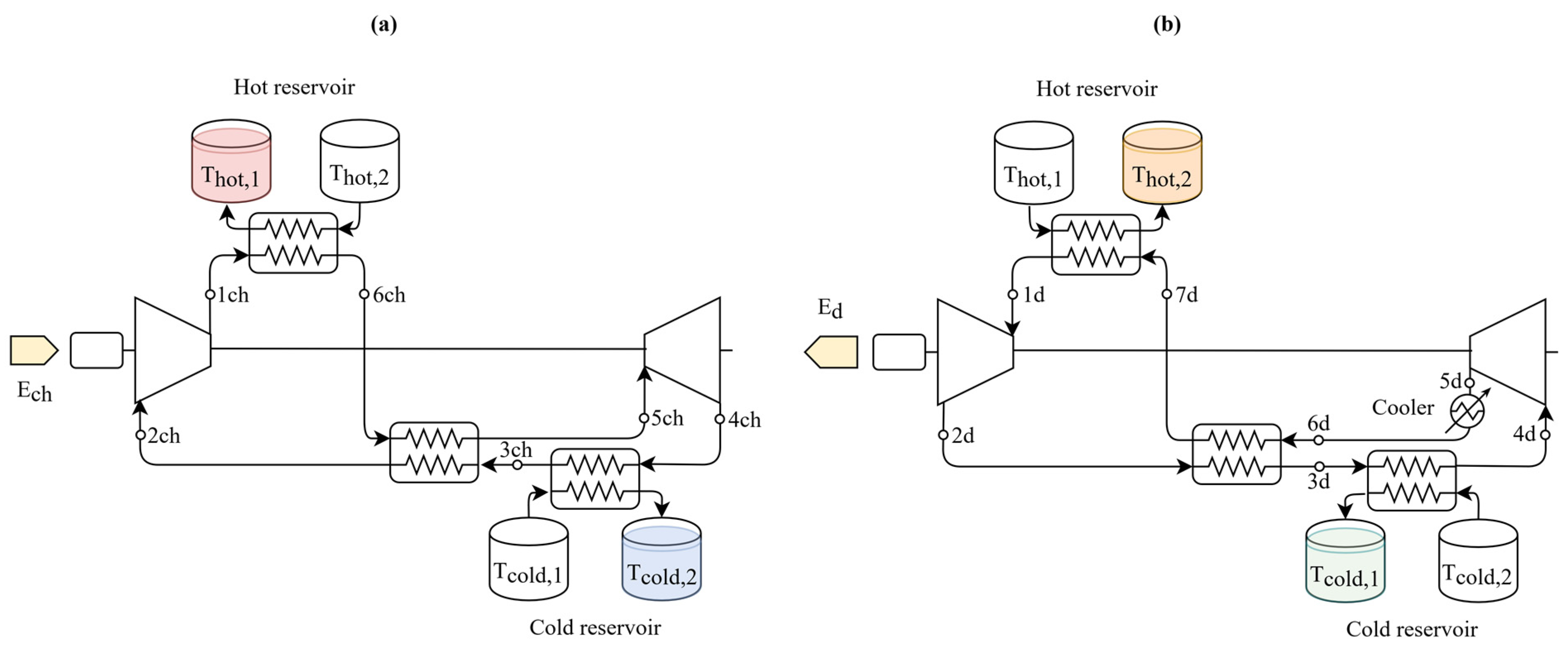
Figure 1. Brayton PTES system with liquid-based thermal exergy storage (LBPTES): (a) charge system; (b) discharge system.
Energies 15 09595 g001
Figure 2. Brayton PTES system with solid-based thermal exergy storage (SBPTES): (a) charge system; (b) discharge system.
Energies 15 09595 g002
Figure 3. Brayton PTES systems thermodynamic charging and discharging cycles: (a) system with solid-based thermal exergy storage (SBPTES); (b) system with liquid-based thermal exergy storage (LBPTES).
Energies 15 09595 g003
Figure 4. The trade-off (Pareto fronts) between cost and roundtrip efficiency for the LBPTES system. The results are related to air, argon and nitrogen; the cost was normalised with its maximum value to highlight the relative cost increments along the fronts and between the different fluids.
Energies 15 09595 g004
Figure 5. Impact of the operating fluid on the cost for the SBPTES. The results are related to air, argon and nitrogen; the cost was normalised with the maximum value to highlight the relative cost increments between the fluids. The results refer to a configuration with ηrt ≈ 0.58.
Energies 15 09595 g005
Figure 6. Cost categories for SBPTES (a) and LBPTES (b) systems for different operating fluids. Auxiliary comprises electric motors and generators; HEX accounts for heat exchangers and air coolers; Machines comprises turbines and compressors; TES materials represents hot and cold reservoir storage media; finally, TES tank comprises hot and cold reservoir containers. The results are related to a case with W ˙ n e t , c h = 50 MW, τch = 8 h and Rut = 0.8. For LBPTES, the results refer to a configuration with ηrt ≈ 0.58.
Energies 15 09595 g006
Figure 7. Comparison between the roundtrip efficiency and cost in MEUR achieved by LBPTES and SBPTES systems. The results are reported for three values of nominal power rating (25, 50 and 100 MW) and refer to a nominal charge duration of 8 h. For SBPTES, the capacity utilisation ratios (Rut) equal to 0.4, 0.6 and 0.8 are reported.
Energies 15 09595 g007
Figure 8. Comparison between the energy- and power-specific costs of LBPTES and SBPTES: (a) energy-specific cost in EUR/kWh of the equipment dedicated to energy storage; (b) power-specific cost in EUR/kW of the equipment dedicated to converting power into thermal exergy and vice versa. The results are related to nominal power ratings from 25 to 100 MW and nominal charge durations from 4 to 8 h. For the SBPTES, capacity utilisation ratios (Rut) equal to 0.4, 0.6 and 0.8 are reported.
Energies 15 09595 g008
Figure 9. Cost categories for the LBPTES and SBPTES systems. Auxiliary comprises electric motors and generators; HEX accounts for heat exchangers and air coolers; Machines comprises turbines and compressors; TES materials represents hot and cold reservoir storage media; finally, TES tank comprises hot and cold reservoir containers. The results are related to a case with W ˙ n e t , c h = 50 MW, τch = 8 h and Rut = 0.8.
Energies 15 09595 g009
Table 1. Performance of turbomachines and heat exchangers. Pinch points (pp, in K) represent the minimum value of the temperature difference that can be realised in the heat exchangers. Tmax,cmp in °C is the maximum allowed temperature at the compressor discharge.
Parameterηis,cmp
(-)
ηis,tur
(-)
ηel
(-)
pphot
(K)
ppcold
(K)
ppreg
(K)
ppcool
(K)
Tmax,cmp
(°C)
SBPTES0.870.920.9511-10600
LBPTES0.870.920.9522210600
Table 2. Hot and cold reservoir operating temperatures. Data from [10].
ParameterThot,1
(°C)
Thot,2
(°C)
Tcold,1
(°C)
Tcold,2
(°C)
SBPTES590optimisedoptimised−100
LBPTES50030015−80
Table 3. Simulated cases.
Parameter W ˙ n e t , c h / d
(MW)
τch
(h)
FluidRut
(-)
SBPTES25–50–1004–8argon–nitrogen–air0.4–0.6–0.8
LBPTES25–50–1004–8argon–nitrogen–air-
Table 4. Operating conditions of LBPTES and SBPTES systems for different operating fluids. The results are related to the nominal power rating of 50 MW and a charging duration of 8 h. For LBPTES, the results refer to a configuration with ηrt ≈ 0.58.
TechnologyFluidsCharging CycleDischarging Cycle
p h i g h / p l o w (-) m ˙   ( kg / s ) p h i g h / p l o w (-) m ˙   ( kg / s )
SBPTESAir8.03159.2413.10273.16
Argon4.56311.246.54545.56
Nitrogen8.07154.8613.17267.30
LBPTESAir3.85210.733.22464.93
Argon2.46434.752.22951.72
Nitrogen3.80206.273.21452.52
Table 5. Operating conditions of LBPTES and SBPTES systems. The results are related to the nominal power rating of 50 MW and a charging duration of 8 h.
TechnologyCharging CycleDischarging Cycle
p h i g h / p l o w (-) m ˙   ( kg / s ) p h i g h / p l o w (-) m ˙   ( kg / s )
SBPTES8.03159.2413.10273.16
LBPTES3.85210.733.22464.93
Publisher’s Note: MDPI stays neutral with regard to jurisdictional claims in published maps and institutional affiliations.