1. Introduction
The exploitation of raw materials in underground mines is associated with many natural hazards. In deep mines, one of the dominant threats is the climate. Its scale depends on many factors that have been presented recently [
1,
2,
3,
4]. The basic threat is the primary temperature of the rocks, also called virgin rock temperature (VRT). VRT depends on a geothermal temperature at a given mine location. For example, at a depth of 1000 m, during the exploitation of the gold deposit in the West Wits Basin, VTR reaches 20 °C [
5] and 44 °C in the Jastrzębie coal mines, Poland [
6]. The VTR is related to the different geothermal temperatures.
The state of climatic hazards at workstations in deep mines is also affected by proper planning of underground workings, rational ventilation and organization of the technological process, primarily the transport of mined output, materials and the location of heat-emitting equipment.
The above-mentioned factors influence the fact that various air conditioning systems are used in mines. Their specificity depends on the deposit exploitation systems used but are also adapted to legal and climatic conditions in a given country. In European coal mines, closed refrigeration circuits are used to cool mine air due to the widespread use of electrical machinery and equipment.
The choice of a cooling system is primarily determined by the demand for cooling power in the mining area of a mine. The specificity of air cooling in deep hot mines is the constant demand for cooling power regardless of the season. An important factor is also the type of refrigeration units used and the possibility of heat rejection. A particular limitation in the application of the cooling system may be the distance between the areas of mining work and the locations of the refrigeration units.
Primary, secondary and tertiary cooling systems are used in subsurface mines worldwide [
7]. In a typical coal mine, the length of all underground roadways exceeds 100 km. The distance of workplaces from downcast shafts is usually greater than 5 km. Primary and secondary cooling systems are not effective in such vast mining areas. Therefore, a tertiary cooling system is used, consisting of air cooling by movable coil exchangers called spot air-coolers, which are placed close to workplaces. Such cooling devices are also called mobile spot air-coolers [
7,
8,
9,
10]. Water cooled in a refrigerant plant is distributed to closed-circuit cooling-coil heat exchangers (indirect coolers) in mining districts.
Cooled water circulates in a closed pipe circuit distributed along the roadways. Several dozen spot air-coolers can be connected to the pipeline network several kilometres from the refrigeration plant.
Underground or surface refrigeration plants are used for chilling water. In surface cooling stations, several chillers are connected in a cascade system. Both compressor and absorption units are used. The condensation heat of the refrigerant in compressor chillers is rejected to the atmosphere. In the event of an increase in the demand for cooling power, such surface cooling installations can be expanded to certain limited extents. The limit is the capacity of the chilled water through the vertical pipelines. For technical reasons, pipe diameters in air shafts are not larger than 300 mm. This allows for achieving cooling capacity in the surface refrigeration plant (SRP) up to about 15 MW. Such cooling systems are described in [
11,
12,
13]. However, in the case of large distances between SRP and workplaces, the temperature of chilled water flowing through pipelines increases [
14,
15]. This is due to water supply through vertical pipelines and the Joule-Thompson effect. The solutions in the hydrostatic pressure reduction of the water column between vertical and horizontal pipelines are also required.
Therefore, increasingly, the construction of underground refrigeration plants (URP) with a greater cooling capacity than in the systems built so far is being considered, and practical, economically justified removal of the heat of condensation is sought.
In the case of underground refrigeration plants consisting of stationary chilling machines, the heat of condensation is usually rejected into return air flowing in ventilation roadways toward upcast shafts using evaporative water coolers. Until now, URPs equipped with compressor cooling machines have been used in Poland if the cooling power demand does not usually exceed 2.0–3.0 MW [
7,
16]. URPs with higher cooling power are usually not built because it is impossible to dissipate more condensation heat from the refrigerant. This is due to the thermodynamic parameters of the air and its flow in mine excavation.
The previous experience related to the use of underground plants and the transfer of heat to the air shows that:
Rejecting condensation heat into mine air streams is crucial for the correct operation of the underground cooling plant.
Heat rejection to the mine air is often associated with the need to install evaporative water coolers at a considerable distance from cooling units (this necessitates building long pipelines connecting evaporative water coolers with cooling units and installing circulation pumps to overcome resistance in these pipelines).
The forcing fan must be placed in the evaporative water cooler, which increases the cooling system’s energy consumption.
In the case of heat transfer to the mine atmosphere, there are problems related to ensuring appropriate air parameters at the location of evaporative water coolers (too high air temperature, too high humidity, ensuring adequate water flow).
Another way of transferring the heat of condensation from the URP is to transport water through vertical pipelines in the intake air shaft to the surface, cool it, and bring it back down the mine. However, the cost of pumping water has kept such systems from becoming widespread. Xu et al. [
3] presented a method of using mine water in the surface-subsurface circulation cycle. From this circulation, part of the cool water from the surface can be transferred to URP, and part is passed through the post-mining goaf.
It is confirmed that the heat condensation from the compressor units can be transferred to the service water or dewatering system of a mine. That integrated system is called the water reticulation system [
9]. In the case of electric-powered coal mines, the consumption of service water is minimised, and the inflow of natural water from the strata depends on the geological conditions of a particular mine. In such mines, efforts are made to minimise the mine water circulation. Increasing service water use is out of the question in mines if the dewatering system does not have enough capacity in reserve. Therefore, attention is drawn to using the inflow of natural water from the strata to the workings of the real-life mine. Natural water is also called fissure water.
There are two different sources of water inflow to the dewatering system in mines: ground water (known as fissure water) and mine water (known as service water). Service water consumption in Polish mines is small compared to world mines and constitutes only a small percentage of the total water pumped out to the surface.
The main objective of the dewatering system is to capture fissure water at the outlet points and supply it to the surface of the mine. In mines, most of the water inflows by gravity from the mining areas to the central chamber of the dewatering pumps. The main drainage chambers play a crucial role in the entire system, in which pumps pumping water continuously to the surface are installed. The total water inflow to the pump chamber is related to the inflow of fissure water and service water.
The total water inflow limits the possibility of rejecting condensation heat in mine dewatering systems to the system. Polish mines belong to mines with a small inflow of fissure water. Currently, the largest amounts of water inflow to mines vary widely, from about 20 m
3/h to over 3600 m
3/h [
17]. The average inflow is about 700 m
3/h. However, the water inflow’s structure is various, so water is often pumped out from different areas of the mine and different levels. Such a drainage system makes it impossible to receive heat rejection from the refrigeration plant fully.
Water from underground settlers can be pumped to the surface indirectly (in two or more stages) or directly. The method of pumping out water in the mine depends on its inflow and the number of active mining levels. In Polish conditions, direct water drainage to the surface is primarily used in large water inflows. In the indirect dewatering system, water is transferred between depth levels and then to the surface. In such a situation, the primary drainage chambers are located at the level with the greatest water inflow. Water can also be transferred by gravity or by pumps between levels.
Water from mine drainage is partly used on the surface. On average, about 1/3 of the water pumped out on the surface is used in mines. The rest of the water is discharged as wastewater. Depending on mine water’s salinity degree, some mines are forced to direct water to a desalination plant.
The concept of using water from the dewatering system to reject the refrigerant condensation heat was considered for one of the coal mines. The idea is to transfer mine water through the condensers of underground chillers and pump it to the surface. To develop a technical solution, it was necessary to analyse the possibility of rejecting heat for the maximum cooling capacity of the designed URP, technical possibilities of water purification and pumping, analysis of the temperature of water flowing into the main pumping chamber, analysis of the temperature of water pumped out to the surface, and the possibility of using low-temperature heat from water on the surface.
Cooling is an energy-intensive process. Therefore, such a system must be as efficient as possible [
9,
18]. Increasing air cooling efficiency can be implemented in many ways, depending on the various solutions used. One way is to recover condensation heat from chillers for heating purposes. For example, in energy infrastructures of mines, there are heating needs related to, among others, heating of rooms, utility water and air inlet to shafts [
19,
20,
21].
This paper presents the implemented solution for transferring condensation heat from chillers in URP to the mine dewatering system. The objective is a detailed examination of the condenser circuit. The conditions the dewatering system must meet will be analysed to use this method in similar mines. Determining the possibility of utilising recovery heat from cooling chillers is a crucial aspect that should always be considered. The presented example is a kind of energy optimisation in cooling underground excavations with URP.
3. Results and Discussion
3.1. Energy Balance of Refrigeration System
Air cooling systems are characterized by high energy consumption. The main energy-intensive devices are motors of chiller compressors and water circulation pumps.
Analysed URP has 5 chiller units, including 1 unit with a capacity of 2000 kW and four units with a capacity of 1000 kW. The units are connected in parallel to the chilled water pipeline network and the condenser cooling pipeline network, respectively. The total condenser power of these chillers is 7800 kW. The electric power of compressor motors in chillers is 2050 kW. The energy efficiency ratio (EER) is 4.18 and 4.22, respectively.
The second significant source of power demand is circulating pump drives. Electric power demand for pump drives is given by Equation (2):
where
is the volumetric flow rate of the pumped water in m
3/s,
is the water density in kg/m
3, Δ
h is the pump head in m,
is the gravitational acceleration in m/s
2, and
is the efficiency of the pump system.
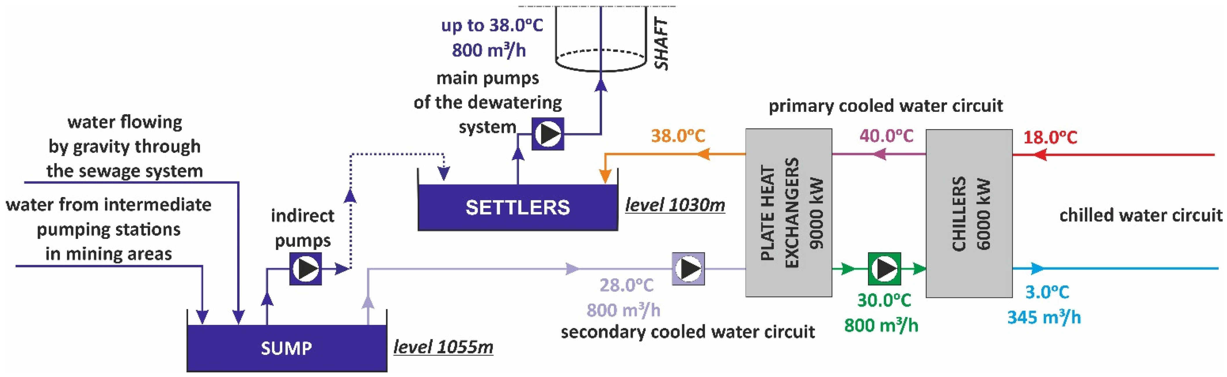
The calculations were carried out in accordance with the water parameters shown in
Figure 2. The results of calculations of pump drive power are presented in
Table 1.
The additional demand for electric power in the URP is 100 kW, related to the drives of automatic damper actuators, drivers and controllers, and lighting. The total electric power demand in the URP is 2800 kW.
The chilled water installation includes fan drives in 17 spot air-coolers and automatic dampers. The electric power demand in a chilled water circuit is 450 kW.
The designed cooling system is assumed to operate continuously throughout the year, with the same cooling capacity. The cooling power demand is constant regardless of the season and outdoor air parameters.
The total demand for electric power in the cooling system is 3250 kW, resulting in electricity consumption of 78 MWh per day.
If the cooling water from the URP had to be transported to the surface through a 1030 m long vertical pipeline, the chiller condensers would have to be increased by 3350 kW. Such an increase in power demand in the cooling system is unacceptable due to operating costs. Therefore, the solution is to pump the water into the air through the existing mine dewatering system.
3.2. Energy Balance of Dewatering System
A mine dewatering system also generates high costs related to the operation of pumps due to the lifting height and high capacity of pumped water in the shaft. In the analysed case, the power of the pump sets in the dewatering system is about 3500 kW. Every day, pumps consume around 84 MWh of electricity.
Due to the costs incurred, it is reasonable to use water to receive the heat of condensation of the refrigerant in chillers. The temperature of the water pumped out from the bottom shaft at level 1030 m is 38 °C. Therefore, it is necessary to consider the water temperature change in the shaft pipeline. The expected water temperature on the surface is required to determine the possibility of its use and removal.
3.3. Predicted Temperature of Mine Water on the Surface
As air flows from the inlet of the shaft to the bottom of the shaft, the air’s temperature and moisture content vary along its length. The reason is the heat and mass exchange between the strata and the airflow in the shaft. The shaft wall temperature varies with depth as a result of the geothermal rock gradient. Masses of moisture or infiltration water can flow from the surrounding rocks into the shaft. In addition, there is heat exchange between the air and devices or pipelines transporting media in the shaft. Air self-compression due to height differences is also an essential factor. In the Halemba mine, a significant internal heat source is the pipeline transporting hot water from level 1030 m to the surface. The nature of airflow in the shaft and water in the pipeline is like a pipe-in-pipe with counter-current flows. However, mass and heat are exchanged between the shaft (outer tube) and the strata. Methods of predicting air temperature and humidity in air shafts are known [
26]. The analytical solutions to determine heat and mass transfers in mine shafts and heat exchange between flowing counter-current air in the shaft and water in the pipe were adopted during design. The solution is given by [
27,
28,
29]. The authors of these works presented a simplified solution to the differential equations of heat and moisture transfer to vertical workings. The assumptions are that the surrounding rocks are isotropic and homogeneous, and the virgin temperature of the surrounding rock varies linearly with depth. The heat and mass transfer from the rocks to the airflow is steady, and their directions are perpendicular to the axis of the shaft. The steady state of the heat flow is related to the shaft’s ventilation time by considering the period from the moment of its construction to the present. Seasonal change in outdoor air is taken into consideration. In the analysed shaft, the water inflow from the rock mass is about 3.5 m
3/h. Other air and water flow parameters are presented in
Table 2.
The temperature of pumped-out water on the surface depends on the inlet air temperature of the shaft and the temperature of the water at the level of 1030 m. For the prediction of water temperature on the surface, calculations of heat exchange between the water pipeline and the air in the shaft were made based on the models given in [
27,
28,
29]. Calculations were made for the summer, transitional and winter periods. Assumptions of air parameters for these periods are given in
Table 3. The results of the calculations are shown in
Figure 5.
The calculation results show that water temperature on the surface will vary from 33.6 °C in winter to 37.3 °C in summer, depending on the season. The legislation of many countries complains discharging of used water from industrial plants to surface watercourses not only on the composition but also the temperature of the water. For the Halemba mine, the maximum water temperature discharged as wastewater cannot exceed 35 °C [
30].
It follows from the above that periodically the temperature of the water pumped to the surface will exceed 35 °C, resulting in the water having to be cooled before discharge to the sewage.
3.4. Heat Demand of the Surface Infrastructure of the Mine
European underground mines are characterized by a high demand for heat in the winter. The heat is mainly demanded in heating the surface infrastructure buildings, producing domestic hot water, and heating the inlet air to the shafts. There are many ways to use waste heat to cover these needs. Very often in mines, waste heat from various processes is considered. However, the difficulties lie in correlating waste heat parameters’ quantity and continuity with the plant’s energy needs.
In the analysed example, the possibility of using the heat contained in the mine water to cool the chiller condenser in URP was considered. The transfer of condensation heat from the underground chillers to the water pumped to the surface increases its temperature. Periodically, the water is too hot to be discharged into the sewer and needs to be cooled down. Thus, water has a certain energy potential that allows it to be used for heating purposes. This heat can be used directly or through heat pump systems. The article’s next section presents the concepts of such water use.
Energy needs on the surface of the mine were analysed to assess the possibility of assessing the use of waste heat. Analyses have shown that in winter, it is possible to use heat to power three installations:
heating of domestic hot water up to the temperature of 65 °C—constant heat demand throughout the year;
heating the air in the inlet shafts—the required temperature of the heating water is 90 °C—variable heat demand;
heating of buildings at 65 °C—variable demand when outdoor temperature drops below 15 °C.
The hot-utility water installation ensures surface facility users’ living and technological needs. The largest tap water consumption is caused by employee baths, departmental workshops and the living needs of office buildings. The average daily hot water consumption per employee is 60 dm3. The mine employs 3125 people, which gives a total water consumption of 187.5 m3/day. The heat load for domestic hot water is 500 KW. About 12.0 MWh of thermal energy is used to prepare domestic hot water during the day. It is assumed that the demand for heat for domestic hot water preparation is constant throughout the year.
Following the legal requirements in many countries, it is necessary to heat the inlet air to the mine in winter to avoid freezing the shaft hoist elements. The heat demand for air heating in the intake shafts depends on the outdoor temperature and the flow rate of the inlet air into the mine. About 12,000 m3/min of air (240 kg/s) flows through the inlet shaft, where a pipeline discharges water to the surface. The peak power of the air heaters in the inlet shaft at a design temperature of −20 °C is 5.0 MW. The calculations assume that the air is always heated to the temperature of 1 °C required by law, and the heat demand depends on the outdoor air temperature.
The peak heat load of buildings at an outdoor air temperature of −20 °C is 80 W/m2. The thermal power demand for heating buildings with an area of 5000 m2 is 4.0 MW. In calculating the heat demand for the heating system, the heat load depends on the outside air temperature.
The assumptions presented above indicate that, apart from the domestic hot water installation, the demand for heat energy varies throughout the year and depends on the outside air temperature. The peak heat demand for the outdoor air temperature of −20 °C was determined separately for each installation. However, this demand is infrequent. As the outside air temperature increases, it decreases, as shown in
Figure 6.
However, the graph presented in
Figure 6 does not show the heating demand; rather, it shows only the heat load variability. Therefore, using statistical climatic data for Katowice, changes in heat demand and outside air temperature were analysed.
Figure 7 presents the frequency of occurrence of temperatures in the area of the Halemba mine. The presented graph shows that very low air temperatures are relatively rare, and then the thermal loads of the systems are the greatest.
Based on the heat demand diagram for the analysed mine and the temperature frequency diagram, an ordered diagram of the hourly energy demand in kWh was developed, shown in
Figure 8. The total annual demand for heat in the mine is 17,153 MWh/year (61,750 GJ/year).
3.5. The Concept of Heat Recovery Utilization from the Refrigeration System
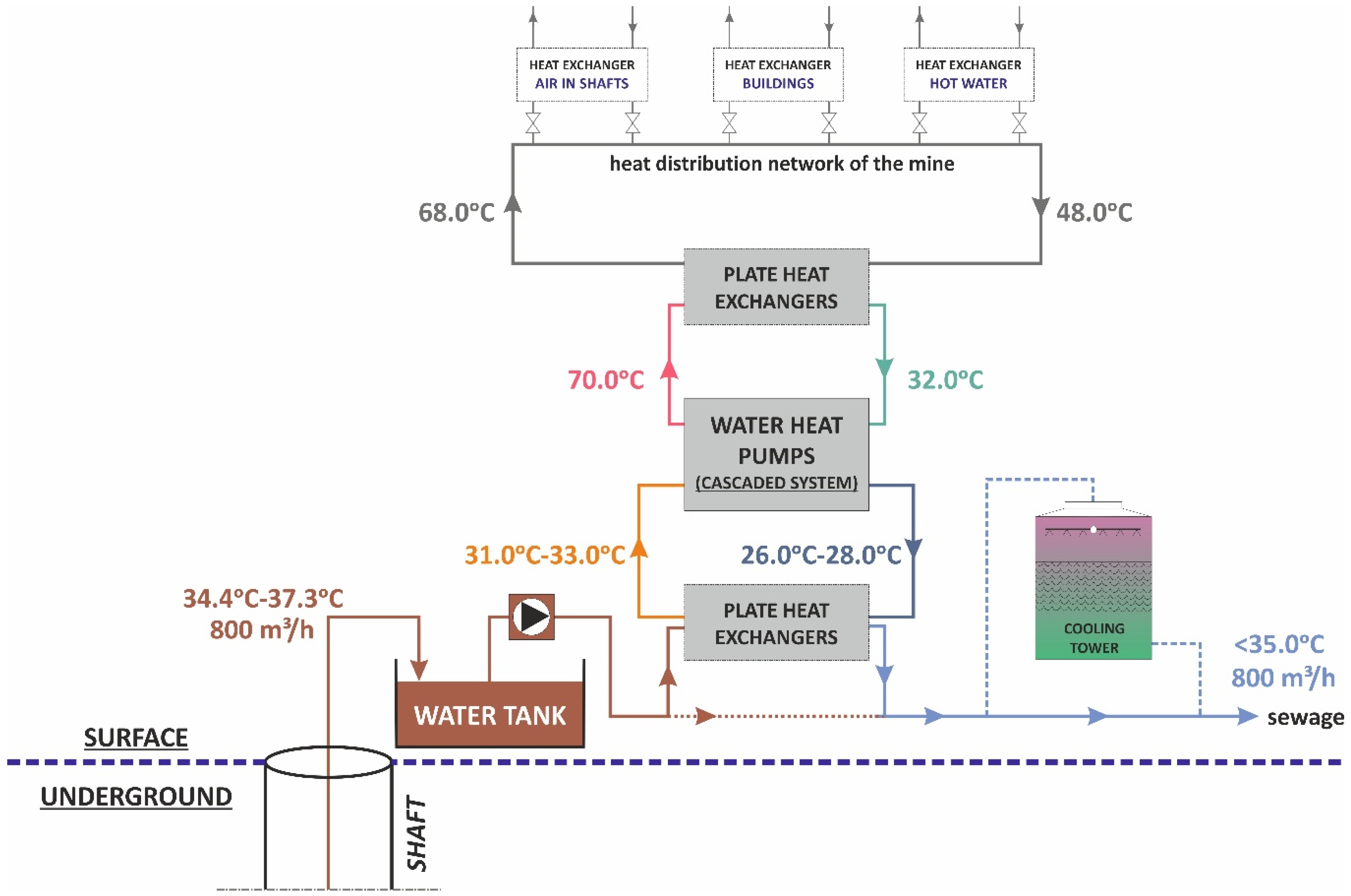
The possibility of using waste heat from the mine dewatering system was analysed based on the assumptions. The temperature of the water pumped by the dewatering system to the surface is too low and does not allow for its direct use. Therefore, to use the waste heat contained in it, the use of water-to-water heat pumps was considered. Due to possible water contamination, and thus the protection of heat pump evaporators, an intermediate heat exchanger was used. In the event of a heat demand lack, a cooling tower is also provided to cool the water before it is discharged into the sewage system.
Figure 9 shows a schematic diagram of the solution for obtaining waste heat from mine water pumped on the surface.
It is assumed that the heat from the mine water will be transferred to the district heating system in the summer to heat the domestic hot water installation. The water will be cooled by 10 °C by a set of heat pumps (cascade system). The temperature difference of the water on the upper heat source will be 38 °C. Therefore, a set of heat pumps with the coefficient of performance COP = 3.8 was selected.
Figure 9 shows the heat exchangers included in the mine’s heating system.
When it is impossible to transfer heat to the district heating network, the water can be cooled in a cooling tower. A cooling tower with a cooling capacity of 3000 kW was selected. This cooling tower is a reserve installation in case of a heat demand lack during the summer. The water is discharged into the sewage treatment system, which will operate the same way as before. The cooling system in the mine is under construction.
4. Conclusions
The solution is the first underground refrigeration plant of this type with such high cooling power in the Polish mining industry, in which virtually all water from the mine dewatering system is used to receive the condensation heat of refrigerant in an underground refrigeration plant (URP).
The use of mine water, which is constantly pumped to the surface, allows the design of URP with a capacity of more than 3000 MW or the extension of existing plants.
The transfer of condensation heat from the chillers in the URP to the water significantly increases its temperature. Therefore, if the heat demand in the surface infrastructure of the mine is sufficiently high in the summer, heat recovery from the water heated in URP brings definite benefits.
Using such a solution was possible thanks to the specific dewatering system of the analysed mine. The dewatering system has a constant supply of service and fissure water with a constant temperature throughout the year.
In the analysed case, the specific enthalpy of water discharged to the surface is 160 kJ/kg. The heat demand for domestic hot water preparation in summer is 500 kW. In winter, the heat demand in the surface infrastructure is 9700 kW. Depending on the needs, the heat can be used for various installations in the mine.
However, heat demand in the summer is small, and the mine water can exceed the temperature of 35.0 °C. Therefore, reserve water cooling towers are needed. However, the cooling towers are predicted to have a short usage period.
The results show that the energy potential of the UCP condensation heat transferred to the water discharged from the mine allows partial coverage of the heat demand on the surface of the mine in winter by using water-to-water heat pumps. The results also indicated that using mine water for heat rejection from URP in electric-powered mines might be suitable for designing and building underground air cooling systems.


