1. Introduction
The very large costs associated with particle physics experiments and the large groups of specialists needed for running them limit the progress in this field, which is of central and immediate importance to humanity. Its present direct importance is due to the urgent need to find better methods of nuclear energy generation for stopping global warming by replacing non-sustainable fuels like coal, oil, gas and uranium with better nuclear energy sources like deuterium and protium. The hope for a better energy future has for 60 years or so relied on the development of large-scale fusion reactors. However, they have shown very little advancement during that time due to the choice of very complex and non-sustainable solutions using the D + T fusion process by magnetic or inertial confinement. Much simpler solutions are indeed possible using sustainable D + D fusion in the form of muon-catalysed fusion, which is well-known [
1,
2] and which has been studied by many large groups since its discovery in 1957 [
3,
4]. It is highly unfortunate that muon-catalysed fusion which does not require radioactive tritium as fuel, has not been selected as the main method for the development of fusion energy. Even better methods for nuclear energy production indeed exist, like annihilation energy generation [
5,
6]. This baryon annihilation method using H(0) is under commercial development at present. Thus, methods to make particle physics studies more amenable and accessible to small, highly creative research groups are of vital importance to society and humanity. Here, a table-top meson generator or miniature meson factory [
7] which facilitates such studies is described and verified. It uses a pulsed laser for inducing nuclear reactions in ultra-dense hydrogen. The laser pulse creates the mesons and provides the starting time for their decay, which creates the muons finally detected in the present study.
The novel nuclear fuel ultra-dense hydrogen H(0) has been the subject of some reviews in recent years, for example, one on the new fundamental physics behind its properties [
8] and one on the atomistic details of its production processes [
9]. The present contribution is motivated mainly by the need for more easily used meson generators to develop better nuclear energy processes, as argued above.
Another motivation is the general misunderstandings about meson formation processes observed in many referee and editor comments. Many scientists even in the nuclear field believe that meson formation is forbidden by baryon conservation [
10,
11]. This is the case despite the numerous studies of meson formation in so-called meson factories [
7] and also despite the numerous studies of meson-producing baryon annihilation [
12].
The present study contains results on the decay time constants for charged kaons K
± and long-lived neutral kaons
and accurate measurements of the energy of these mesons ejected in the most complex baryon annihilation production mode observed so far [
5,
6]. Results of the same type for charged pions
π± are also given. Such results have not been published in full previously and should remove some obstacles for the necessary scientific and technological development.
2. Ultra-Dense Hydrogen H(0)
The fundamental physics of the quantum material ultra-dense hydrogen H(0) was described in a review paper in Physica Scripta in 2019 [
8], covering the approximately 50 publications on H(0) existing at that time. H(0) has been known and studied since 2009. With interatomic distances of 2.3 ± 0.1 pm in the most often observed spin level
s = 2 at low pressure and temperature in the laboratory [
8,
13], this is the densest form of matter that exists in our solar system. In spin level
s = 1, the density is 1000 kg cm
−3. Even more precise interatomic distances giving 2.245 ± 0.003 pm at
s = 2 have been measured [
14] with an uncertainty of 3 fm. As expected for a dense hydrogen phase [
15], H(0) is superfluid [
16] and superconductive [
17], and this is so even at room temperature. This means that H(0) is shown to have the expected properties for a dense hydrogen phase. So called metallic hydrogen is formed spontaneously from H(0) and is named H(1) [
8]. Clear transition temperatures for H(0) to a normal (i.e., a non-superfluid) state exist at several hundred K above room temperature [
18]. This ultra-dense material has been studied mainly by laser-induced processes like Coulomb explosions (CE), coupled to time-of-flight (TOF) or time-of-flight mass spectrometry (TOF-MS) [
8,
13] of its molecular fragments, but also by rotational emission spectroscopy [
8,
14]. The rotational spectra give femtometer resolution and precision of the H-H bond lengths in H(0) as a function of spin level
s. The relations between the three forms of condensed atomic hydrogen, (1) ultra-dense hydrogen H(0), (2) metallic hydrogen H(1) and (3) the superconductive and superfluid Rydberg matter forms H(
l), are described in the 2019 review [
8].
Particles with kinetic energies in the high MeV range are easily generated by nuclear processes in H(0) using laser pulses of >0.1 J (0.1–0.6 J) [
8,
19]. Clear signatures of D + D fusion like
4He and
3He ions have been observed by TOF-MS [
19]. Heat generation above break-even from nuclear processes (mainly muon-induced fusion) initiated by laser pulses was published as early as 2015 [
20]. The MeV particle signal gives accurate ns range timing intensity distributions [
21,
22,
23,
24]. The final particle (primarily muon) velocity corresponds to 10–500 MeV u
−1. By using two [
20] and three [
23] collectors in line, it was shown that these particles have mass and that they penetrate through mm thick metal with some attenuation and often a slight delay. Magnetic deflection studies confirm that many of the initially formed particles are neutral and that the mass of the charged particles is in the light meson range or lower [
25]. The generation of muons from meson decay is confirmed by measurement of the accurate decay time for the muons [
26].
3. Theory
Ultra-dense hydrogen H(0) is a quantum material. H(0) is composed of molecules of various forms, mainly super-fluid chain molecules H
2N(0) with the H-H pairs rotating around the central axis (vortex) of the molecule [
8]. Also, other molecular forms are observed, like the common small types H
3(0) and H
4(0) [
27]. These small molecules are not super-fluid but are the ones in which many of the nuclear processes take place [
28]. The ultra-dense states are characterized by their (mixed) spin quantum number s = 1, 2, 3, 4… [
8]. The state
s = 2, which is formed most easily in the laboratory at low temperature and pressure, has a H-H distance of 2.245 pm [
14]. The state
s = 1 is formed both spontaneously at a low rate [
29] and by laser pulse induction [
30]. From this level
s = 1 at an H-H distance of 0.56 pm [
8], it is likely that the nuclear reaction takes place within 1 ns. At similar nuclear distances in so called muon-catalyzed fusion, the rate constant for fusion d + d is 10
9 s
−1 [
1]. This means that the laser field is only required for transferring H(0) from
s = 2 to
s = 1. The laser-induced excitation to higher
s and transfer to
s = 1 can be observed directly in the experiments [
8].
The decay time measurements used to verify the meson types formed require some analysis. The signal current is measured as a function of time at a distance from the laser target in the flux ejected from the pulsed-laser interaction with ultra-dense hydrogen H(0) by detecting elements either (1) by a foil collector, which observes fast charged or neutral particles by the secondary electron current ejected from the foil, or (2) by a current coil, which observes fast charged particles in the beam. The signal always has a steep rise of a few ns to a maximum and an exponential decay, which often agrees well with the known decay times of pions and kaons at rest. This behavior is directly recognized to be due to a reaction chain. Here it means that intermediate particles (mesons) M form and decay as H(0)→M→N. The final particles N are normally muons, and they are the particles which are observed by their interaction with the detecting elements (collectors or coils).
It is clear from the experimental results that the mesons themselves do not generally reach the detecting elements and give the signal there. If they did, no exponential decay would be observed. The signal observed at the detecting elements must clearly be due to particles ejected from the mesons so that the signal is proportional to the number of un-decayed mesons. These particles must also be faster than the initial mesons. They will also certainly have a longer lifetime, so that they do not decay before reaching the detecting element. In the case of most mesons, these fast and long-lived signal particles N are muons.
Watching a meson flux from the laser target with the detecting elements will not show an exponential decay of the signal. Thus, it is clear that the decaying signal observed is due to mesons, which decay long before they reach the detecting elements. The exponential decay of the signal is due to the decay of the mesons close to the laser target, where the mesons decay and eject the fast particles (muons) which give the signal at the detecting elements.
This means that the decays observed in the experiments are due to the decay of mesons relatively close to the laser target, giving primarily muons µ± which generate a signal at the collectors or coils used. This meson cloud is created by the laser pulse interacting with the H(0) layer on the laser target. The decaying signal is due to the decreasing number of muons ejected from the mesons outside the target when the meson cloud decays after its creation. The signal particles in the beam to the detecting elements are mainly muons. Some light particles from the meson decay can move out from the beam due to their high transverse kinetic energy received from the decay in arbitrary directions relative to the beam direction and will not reach the detecting elements. Such examples are muons from the decay of kaons as well as pions. This effect cannot give an exponentially decaying signal. Thus, the exponential time variation of the signal is due directly to the decay of the mesons formed at the H(0)-covered laser target.
The time dependence of the signal is easily derived from the rate equations for the intermediate meson M
(with
k1 and
k2 being rate constants in the chain reaction) as:
as
where n
A0 is the number density of the precursor A at time
t = 0, thus during the laser pulse. Equation (3) is the solution of Equation (2). The initial number density n
M0 of mesons M is assumed to be zero. This solution is not valid if the two rate constants are equal, which does not happen in the meson decays. The curve shape in Equation (3) is used to match the results below and in previous publications [
8,
23,
24,
25]. The timing results are given as time constants
τ = 1/
k. M is a meson, either a kaon or a pion. N is a muon, which is the detected particle type.
It is known that the decay chains from kaons are not strictly linear but contain other steps as well [
31,
32,
33,
34]. When the signal agrees with Equation (3), the linear chain is approximately valid. Departures from this form may be due to competing steps or to two different chains or steps giving the same intermediate particle.
The muons formed normally have kinetic energies > 100 MeV [
23,
24,
25]. This means that the nuclear processes observed are not ordinary D + D fusion processes. From the experiments, it is clear that both kaons and pions can be formed initially with low kinetic energy. However, they are also formed with high energy from baryon annihilation processes and from decay of other particles; for example, some pion pairs may be formed from the decay of kaons.
4. The Meson Source
Many different source constructions using H(0) can generate the mesons. The important point is that the construction must generate ultra-dense hydrogen H(0) [
8] by the interaction of hydrogen gas with a suitable catalyst [
35], for example, a potassium-promoted iron-oxide catalyst of a type used in the chemical industry for styrene production from ethyl-benzene [
36,
37], a so-called styrene catalyst. All details about the catalytic function in H(0) production are given in a recent review [
9]. A Q-switched laser is preferably used to induce meson formation, for example, a Nd:YAG laser with a 5–7 ns pulse length. The laser beam is here focused with a lens of 4–40 cm focal length onto a metallic target plate covered by a thin superfluid phase of H(0) [
8,
16]. The Nd:YAG laser can use either 1064 nm or 532 nm light. Other wavelengths and lasers can also be used, since it is apparently the electric field strength which initiates the transfer in H(0) to
s = 1. A laser pulse energy in the range 90–500 mJ is useful. The possibility of using a matching wavelength of the laser to resonantly transfer even one pair of atoms from
s = 2 to
s = 1 seems very small, since the energy difference is of the order of 500 eV in this de-excitation process, which corresponds to X-ray radiation. The efficiency of triggering the de-excitation with the laser used is high, giving 10
13 nuclear reactions per laser pulse, which has 10
18 photons of 1 eV energy [
38].
Several different constructions have been used for the H(0) source [
29,
30,
35]. In the source, the catalyst forms H(0) from natural hydrogen or deuterium gas at a pressure between 1 × 10
−5 mbar and 200 mbar. The source construction shown in
Figure 1 is the same used in the description for a patented muon generator [
39], and it has been used for numerous particle experiments with a high intensity of mesons, of the order of 10
13 mesons per laser pulse [
2] or 10
14 mesons per second. With a maximum of 100 MeV kinetic energy per particle, this corresponds to >10
21 eV to create this number of mesons in an accelerator. This corresponds also to 1.6 kW just in kinetic energy, while the laser pulses correspond to a power of <5 W. Including also the energy required to form the mesons means a factor of approximately three higher power, thus 5 kW obtained with <5 W from the laser or a factor of 1000 gained relative to the laser pulse.
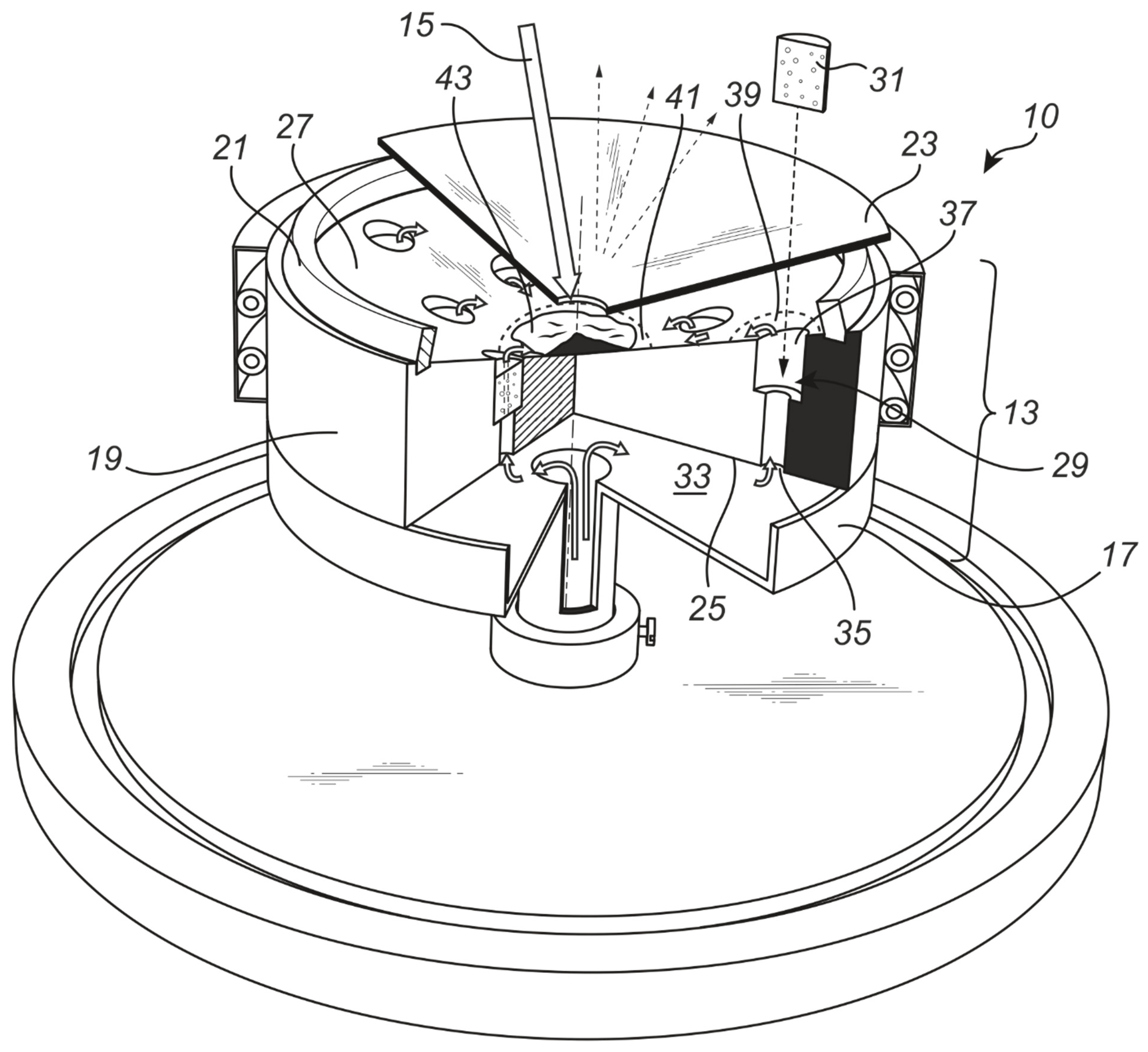
The numbered parts of the source in
Figure 1 are 15: The incoming laser beam hitting the collecting area 43; 17: the wall of the hydrogen gas volume 25; 19: the main steel body of the source, surrounded by a heating jacket, for example, with Thermocoax heaters as shown; 21: a Teflon gasket cut from a Teflon sheet, on which the enclosing lid 23 is residing; 27: the collecting volume for H(0). The source operation requires initial pump-down to remove air (oxygen) from the source. The hydrogen gas enters in the central tube from below, into the volume 33, through the inlet 35 into the space 29, through the porous catalyst pieces 31 where H(0) is produced. H(0) is then pressed out 39, 41 onto the collecting surface 27 and finally to the laser interaction area 43. There are no exposed voltages in the source; only a few W of AC power is fed to the heating jacket in
Figure 1. This is used to heat the functioning source to 50–100 °C, in this way removing any water vapor which may have been absorbed in the catalysts from the air or from the gas feed. Water and oxygen may oxidise the alkali metal promoter so that the catalyst does not function properly. Fresh catalysts may contain alkali hydroxides and carbonates, and it may be necessary to heat the source during pumping to above 100 °C for a few hours to improve the catalyst efficiency by removing the initial carbon dioxide and water.
The pressure in the source can vary from high vacuum (10
−6 mbar) to low vacuum, depending on what particles are intended to be studied. Charged kaon and pion studies are sensitive to high gas pressure since the charged mesons will interact with gas molecules and scatter. Neutral kaons are not so sensitive to a surrounding gas; however, they may still oscillate between long-lived and short-lived neutral kaons [
32,
33,
34] due to collisions with gas molecules, even at pressures in the mbar range. The formation of H(0) works at least up to 200 mbar of hydrogen pressure. The catalysts work best with a partial carbon coverage [
9], so the pumps can be oil sealed fore-vacuum pumps or diffusion pumps with hydrocarbon-based oils [
9]. Silicon-containing pump oils should not be used, since they form an insulating layer on all parts [
9]. This layer prevents the formation of a carbon layer on the catalysts, and without the carbon layer the catalysts will not function correctly.
Most studies using this source have employed a pulsed laser to transfer H(0) from state s = 2 to s = 1, but some studies have instead observed the spontaneous process [
29,
40] which creates mesons, muons and gamma photons. The induced and spontaneous processes appear so far to be quite similar, even if they seem to take place in different parts of the H(0) layer.
5. Observing the Muons from the Mesons
Two 20 µm thick Al foils over a simple wire frame is the preferred form of particle collector, since the thin foils give mainly secondary electron ejection and do not produce so much pair formation [
22] or muon capture and decay processes [
41], which can complicate the signal interpretation. The signal to the collectors was measured by a fast digital oscilloscope (Tektronix TDS 3032, 300 MHz, rise-time 1.7 ns) with 50 Ω input resistance and signal averaging. The rise time of the signal in the figures is down to 3 ns and thus equal to the laser pulse rise time. This proves that no limiting time constant exists due to the measuring circuit. A negative bias voltage is preferably applied on the collectors by a shielded 24 or 50 V battery in series with the oscilloscope input. In this way, all electrons emitted at the collector are removed from the collector, and low-energy electrons released from the apparatus walls by X-ray photons cannot reach the collector. It is easy to verify that the signal observed is due to fast particles in the beam and not to any electronic noise by using valves and beam flags in different locations along the beam from the meson generator to the coil or collector. The same beam-related verification can also be performed by moving the laser impact spot slightly on the source surface.
A suitable current-measuring coil [
42] can be easily wound on a N30 MnZn soft ferrite toroid with epoxy cover (EPCOS) with an inner diameter of 25 mm. Nineteen turns of enameled copper wire wound around it in the negative direction has worked well. The coil was mounted in the meson flux at around a 1 m distance from the source. One end of the coil was connected to the 50 Ω oscilloscope input, while the other end was connected to a 50 Ω termination to signal ground. The difference between these two signals is then the true differential particle signal, with any noise from the plasma cancelled by the subtraction [
43]. The true sign of the signal in the coil was verified in separate tests by passing an insulated wire connected to a square wave signal generator through the coil opening. As described above, the muons observed by collectors or wire coils are due to the decay of mesons created by the annihilation process [
5,
6] which is initiated by the laser pulse. Thus, the decay time observed is caused by the decay of the mesons close to the generator, which gives a decaying muon signal at the collectors or coils.
The long lifetime of the muons µ± of 2.20 µs means that they do not decay inside the apparatus but escape through its walls after, to some extent, having passed through the collectors. Negative muons may also get captured in the walls [
41]. The muons can be measured in air at a few m distance in the laboratory by ordinary energy spectroscopy methods [
29,
30,
44]. Charged kaons and pions will not be able to pass through the steel walls of the chamber, but long-lived neutral kaons
can pass out from the vacuum chamber and can be detected at a distance from the source in air.
6. Meson Verification
The mesons obtained from the described source and their observed decay times are summarized in
Table 1. Just a few examples of the results are shown in the figures here, and several references to published results are given instead. The collector was at a distance of 1–2 m, which means that most of the mesons have time to decay before reaching the collector and thus will not produce a signal there. The muons are so long-lived and have energies close to their ionization minimum that they leave the apparatus through the steel walls. The mesons normally decay close to the generator (laser target), which is clear since otherwise an exponential decay could not be observed at a distance. In some experiments it is observed that pions from kaon decay also reach the collector. The resulting muon flux is observed at impact on the collector by the resulting secondary electron emission. A negative bias on the collector is beneficial for saturating the ejected electron current and for rejecting secondary electrons originating from other parts of the chamber. A battery voltage of 24–50 V is sufficient for this. Since the laser pulses generate meson showers containing both charged and neutral kaons and charged pions, signals with overlapping decay times are often observed, with one example shown in
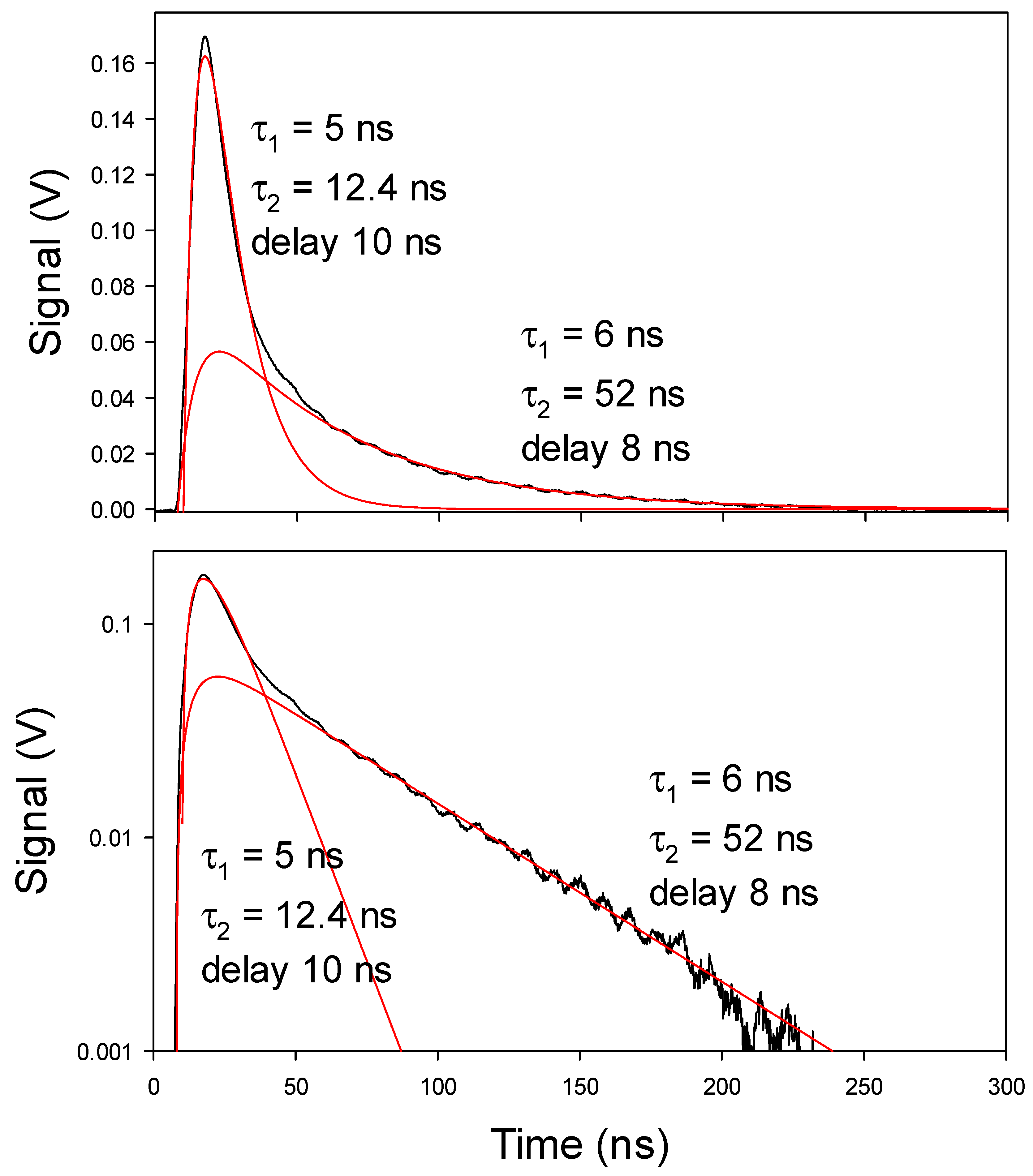
Figure 2.
In the figures, calculated curves from Equation (3) are shown in red, with the timing parameters used shown in the figure. The delay shown around 8 ns is the delay for the start of the calculation relative to time zero in the oscilloscope signal, thus mainly the particle (muon) flight time. The amplitude parameters are not given. The red curves are not least-squares fitted, since such a process is difficult to employ; for example, in
Figure 2, eight parameters in a non-linear least-squares procedure would be needed, which is unlikely to give convergence. Such results would be unreliable. In the table, non-linear least-squares adjustment is indeed used with a two-parameter model to determine the decay time constants in other experiments with only one meson decay.
The results using D(0) or p(0) are not identical concerning the meson distributions, but the meson decay times are the same. The velocities of the main meson groups are derived from the observed relativistically dilated decay times, as also shown in
Table 1. The identification of the slow mesons is easy, for example, after obtaining hundreds of measurements with a 52 ns decay time for long-lived neutral kaons. Also, the accurate decay time constant shown below for charged pions is proof enough for pions; the agreement with tabulated results is reasonable. Note that time-dilated decays are considered only for such meson types that are also observed close to stationary and thus known to be formed.
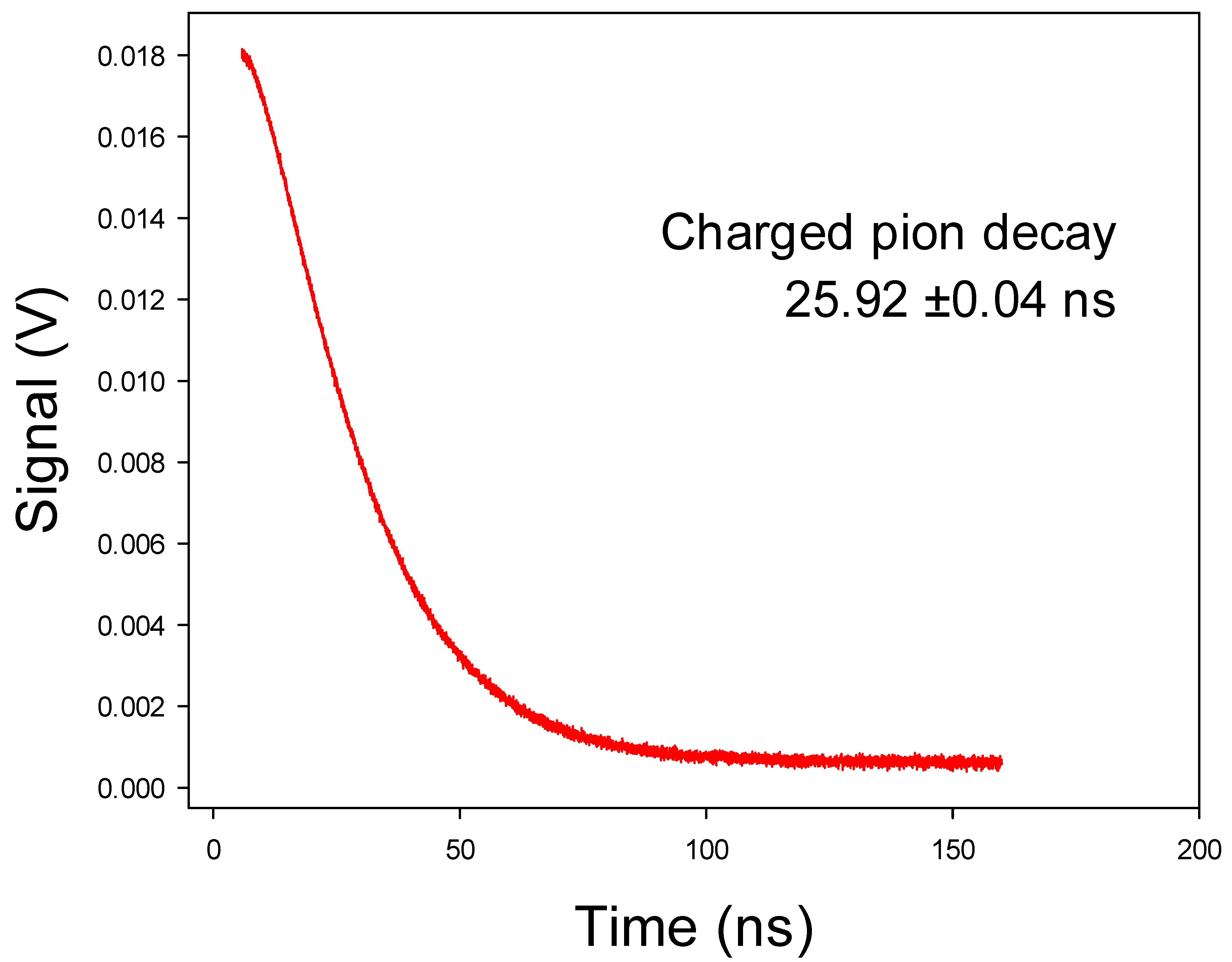
A decay time constant close to 26 ns is often observed. It agrees well with the time constant for decay of charged pions at rest. See
Table 1 and refs. [
32,
34]. One example is shown in
Figure 3. A non-linear two-parameter fit gives the decay time constant as 25.92 ns, with standard error from the fit as ±0.042 ns. Using twice this as the approximate 95% confidence limits gives agreement within 0.4% of the result from the Particle Data Group of 26.03 ns [
34]. Thus, agreement is found, and this time constant shows that these decaying particles are charged pions with low velocity.
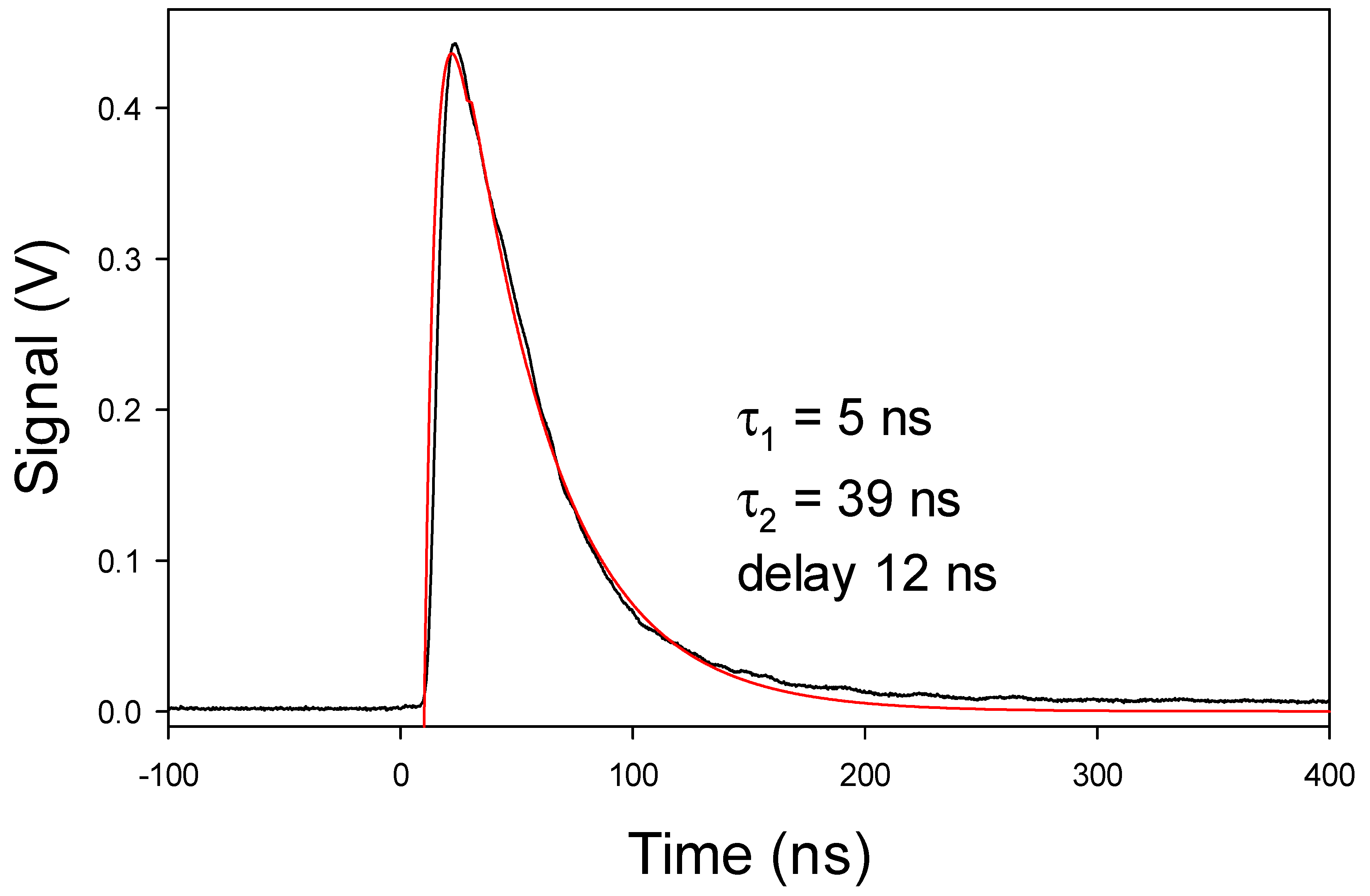
Another common time constant is observed close to 39 ns as shown in
Table 1. An example is shown in
Figure 4. It is likely a dilated time constant from relativistic charged pions. The dilation is thus a factor of 39/26 = 1.50.
Setting this equal to the time dilation expression [
31]
it is found that the particle velocity
vp is 0.745
c, corresponding to a charged pion energy of 69 MeV. See
Table 1.
The results in
Figure 4 can also be used to calculate the total number of particles formed in that experiment with just one meson type to the collector at a 94 cm distance from the generator. The signal observed is approximately 2 × 10
−10 As (calculated from the signal size in V divided by 50 ohms thus in A, times the average width of the signal in s), or 1.25 × 10
9 muons, assuming that each muon reaching the collector gives one charge. The circular collector foil has a diameter of 2 cm, which means a coverage of 2.8 × 10
−5 of the entire sphere. There is no known factor which gives anisotropic emission of the mesons and the muons. Checks of the isotropy have been made in another apparatus, and no anisotropy has been found. Thus, the total number of mouns and their precursor mesons is found to be approximately 4 × 10
13. This approximate value has been repeated in numerous experiments [
2], and slightly larger values of 10
14 particles per laser pulse are not uncommon.
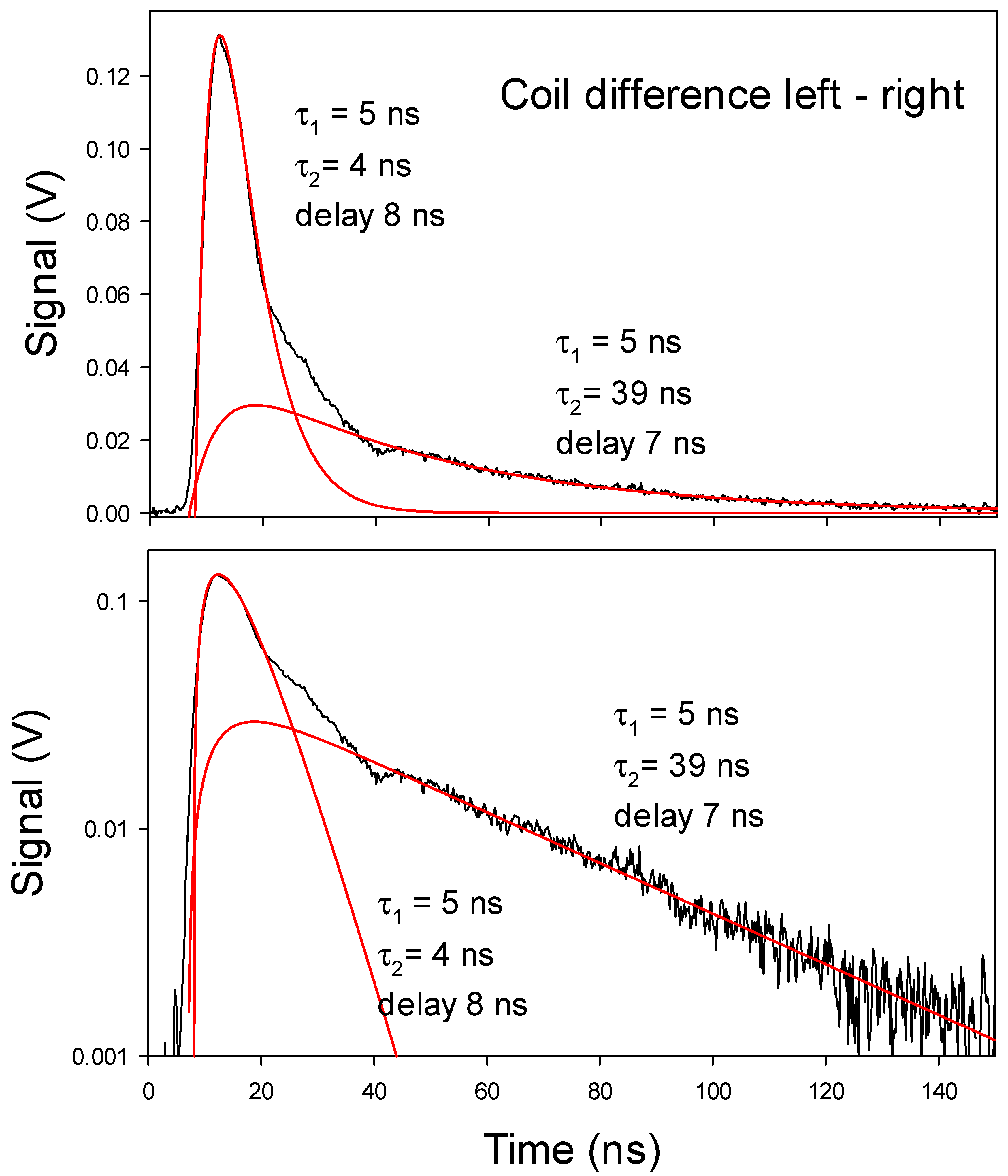
A current coil can be used instead of a collector, with one example in
Figure 5. There a decay time of 39 ns is observed. According to the results above, this is due to time-dilated decay of fast charged pions. The first peak at a few ns time in
Figure 5 could be due to short-lived neutral kaons
.They have a decay time of less than 1 ns [
31,
32,
34], which means that the first peak will follow the laser pulse shape. This indicates then that the charged particles observed by the coil in the first peak are charged pions from the kaon decay, while those giving the later part of the signal are muons from the decay of those charged pions. If the charged pions are formed by pair production, no signal would be observed if equal numbers of positive and negative particles (pions, muons) passed simultaneously through the coil [
43]. The reason for the net charge observed in the signal through the coil here is probably charge separation by a larger capture and reaction probability for the negative particles in the source.
The signal observed is mainly due to muons from decay of the mesons, as described above. The energy of the muons has also been studied by direct time-of-flight from the laser pulse to the detector and by deflection in magnetic fields [
25]. An even better method is to use two collectors at different distances and measure the muon transport time. This has been done, but the results are not of interest for the present meson study. By using two collectors, it is also observed directly that the muons can be formed with different energies in different decay reactions giving different decay times. One such case can be found in Figure 7 in ref. [
8]. This proves directly that the signal is due to muons from meson decay, in that case both from K
± (particle mass 494 MeV) and
π± (particle mass 140 MeV). This means that the muons from the kaon decay have much larger kinetic energy than those from the pion decay, as can be directly observed in this figure in ref. [
8].
7. Baryon Annihilation
Many facts prove a baryon annihilation process as the process giving the mesons observed:
The final proof is a reaction model giving the mesons and their observed kinetic energies. Such a model has been published [
5,
6], and it shows good agreement between the theoretical and experimental energies. The data from
Table 1 are used for this calculation.
The annihilation reaction step for proton + antiproton is well modelled by
where the kinetic energies of the created particles in parantheses are calculated from their dilated decays given in
Table 1 [
5], and the total energy is correctly accounted for at the level of a few MeV (the error limits of the kinetic energies in
Table 1 of a few MeV are not included in the subtraction above).
Pairs of neutral kaons, either long-lived
or short-lived
, often replace the pair of charged kaons K
± in this annihilation reaction, being their own antiparticles. Their masses are slightly larger than for the charged kaons. That this is a replacement can be seen from the good agreement of the experimental kinetic energies for the charged and neutral long-lived kaons in
Table 1, at 95.7 ± 2.0 MeV and 97.4 ± 0.7 MeV, respectively. The agreement of the energies in the annihilation energy cycle is also still good for such reactions. The processes giving the antiparticles which start the annihilation reaction are outside the scope of the present report and will be reported elsewhere. A partial description is published [
6].
The longest decay times measured in the range of 52–60 ns might be due to fast pions instead of neutral kaons. However, since charged kaons are observed with the same dilation factor in
Table 1, it is highly likely that the 52–60 ns decays are due to long-lived neutral kaons
. The 52 ns decay has been measured so many times under varying conditions that the kaon interpretation is the only one possible. The 60 ns decay could be due to a pion with 319 MeV kinetic energy, but this does not fit well into any reasonable annihilation model. In other experiments [
40], kaon creation is further tested by looking for gamma photons from neutral kaon decays. High-energy gamma photons were observed, but due to their high energy, an accurate calibration has not yet been possible.
Possible systematic errors in this study should be discussed. The intention with the present study is not to report new high-precision decay time constants for the mesons, but to use the known meson decay time constants [
34] for identification purposes. However, since this method to measure the meson time constants may never have been used before, a short discussion may be of interest. The meson signals are in the mA range, and there is no background to complicate them. The time base accuracy of the oscilloscope used is the only systematic error source for the measured decay times. One systematic problem may be caused by the interaction between the mesons in each pulse due to the very high density of the mesons close to the laser target. For example, a K
+ + K
− interaction may decrease the charged kaon signal. A similar density-related problem can be caused by the interaction of the mesons with the H(0) molecules. Such an effect is under investigation in another case at present, to be published elsewhere. These effects could possibly influence the observed decay times producing variable results for varying experimental conditions. However, when agreement with known decay times is found repeatedly, such effects are unimportant, and the meson identification is certain.


