Article

Influence of Hydrogen Enrichment Strategy on Performance Characteristics, Combustion and Emissions of a Rotary Engine for Unmanned Aerial Vehicles (UAVs)

1
Department of Mechanical Engineering, Bursa Technical University, Bursa 16310, Turkey
2
Department of Automotive Engineering, Bursa Uludag University, Bursa 16059, Turkey
3
Department of Electronics and Automation, Batman University, Batman 72100, Turkey
*
Author to whom correspondence should be addressed.
Energies 2022, 15(24), 9331; https://doi.org/10.3390/en15249331
Submission received: 10 October 2022 / Revised: 20 November 2022 / Accepted: 28 November 2022 / Published: 9 December 2022
(This article belongs to the Special Issue Combustion and Emission Characteristics of Rotary Engine)

Abstract

:
In recent years, there has been great interest in Wankel-type rotary engines, which are one of the most suitable power sources for unmanned aerial vehicle (UAV) applications due to their high power-to-size and power-to-weight ratios. The purpose of the present study was to investigate the potential of a hydrogen enrichment strategy for the improvement of the performance and reduction of the emissions of Wankel engines. The main motivation behind this study was to make Wankel engines, which are already very advantageous for UAV applications, even more advantageous by applying the hydrogen enrichment technique. In this study, hydrogen addition was implemented in a spark-ignition rotary engine model operating at a constant engine speed of 6000 rpm. The mass fraction of hydrogen in the intake gradually increased from 0% to 10%. Simulation results revealed that addition of hydrogen to the fuel accelerated the flame propagation and increased the burning speed of the fuel, the combustion temperature and the peak pressure in the working chamber. These phenomena had a very positive effect on the performance and emissions of the Wankel engine. The indicated mean effective pressure (IMEP) increased by 8.18% and 9.68% and the indicated torque increased by 6.15% and 7.99% for the 5% and 10% hydrogen mass fraction cases, respectively, compared to those obtained with neat gasoline. In contrast, CO emissions were reduced by 33.35% and 46.21% and soot emissions by 11.92% and 20.06% for 5% and 10% hydrogen additions, respectively. NOx emissions increased with the application of the hydrogen enrichment strategy for the Wankel engine.

1. Introduction

The Wankel engine was invented in 1954 by Felix Heinrich Wankel as an alternative to the conventional piston engine. In a conventional piston engine, the reciprocating motion obtained from the piston-cylinder mechanism must be converted into rotational motion. However, such a conversion process is not required in Wankel engines. In addition to this, Wankel engines have a compact design, excellent power-to-weight ratio and run smoothly and quietly compared to conventional piston engine structures [1,2,3]. However, they have some disadvantages, such as the complex structure of the sealing rings, the ring frictions, high heat transfer from the housing walls due to the high surface-to-volume ratio and high emissions [4,5]. Although important steps have been taken to eliminate these disadvantages, these engines have not made an important move in replacing classical piston engines, which have tremendously extensive production facilities. The excessive demand for unmanned aerial vehicles (UAVs) in the defense industry has opened a new area for the use of Wankel engines. The Wankel engine is the most suitable power source for UAV applications due to its high power-to-size and power-to-weight ratios [6,7,8]. As a result, research on Wankel engines has gained momentum again.
Pisnoy and Tartakovsky [4] developed a methodology to investigate combustion and gas-exchange processes and studied two approaches for improving performance. The first was to add a slot behind the rotor recess and the second was to install a third plug to the rear side, in addition to the two front-mounted plugs in the working chamber. Their results revealed that the proposed three-plug adjustment remarkably enhanced performance and the numerical model they developed proved to be a useful tool for studying various combustion systems. Leboeuf et al. [5] tried to solve the sealing problem in Wankel engines since it is one of the main issues of this type of engine. They developed a new rotary engine named an X engine. The authors overcame the leakage problem in Wankel engines by using a low-blowby sealing system containing two axially loaded face seals directly interfacing with three apex seals per rotor. The performance of this low-blowby sealing system was investigated numerically. The numerical model results showed that the leakage in this new engine design was reduced by about 65% compared to the leakage with a conventional sealing strategy in a similarly sized Wankel engine. These results were also supported by the experimental data published by Kutlar and Malkaz [9]. They established a two-stroke Wankel engine model to investigate performance characteristics and their single-zone simulation results showed that the port geometry affected the engine performance. The port geometry with late opening and early closing showed better performance at low engine speeds. However, as the rotor speed was increased, the engine performance decreased, since the time that the intake port was open did not allow for adequate gas exchange. Finkelberg et al. [10] studied the combustion process in a spark-ignited Wankel engine using a mathematical model. They emphasized the role of recess geometry in the Wankel engine’s combustion and performance. In addition, they offered a new recess design to improve engine performance. Their results proved that the suggested rotor recess geometry reduced CO2 and NOx emissions. Boughou et al. [11] reviewed the effects of the combustion chamber design on rotary engine performance. They highlighted that any changes made in the combustion chamber design, such as changing the recess sizes or the shape factor, resulted in substantial performance improvements. Zhang et al. [12] studied a leaf spring rotary engine with a novel design. Their results demonstrated the effects of the rotor speed, ambient temperature, pressure and equivalent ratio on the combustion phenomenon in the Wankel engine.
The operational conditions and combustion behavior of Wankel engines differ from those of conventional piston engines [13,14,15]. The high surface-to-volume ratio of the Wankel engine increases the heat transfer from the combustion chambers to the rotors and walls, which is the major extinguishing effect [16]. Flame propagates more easily towards the leading edge of the rotor than towards the trailing sides in the Wankel engine. Flame quenching occurs at the cool housing walls on the trailing sides of the rotor. In addition to these findings, studies have revealed that the usage of neat gasoline as a fuel deteriorates the combustion process in Wankel engines due to the gasoline’s low combustion velocity and quenching distance [13]. The challenges mentioned above worsen the combustion performance and the emissions of Wankel engines [17]. On the other hand, recent studies have shown the strategies aimed at improving fuel properties and mixture formation are remarkably effective in minimizing these challenges for the Wankel engine and can improve its combustion process, performance and emissions [18,19,20,21,22]. The special geometry of the combustion chamber in Wankel engines has narrow and long regions which restrict flame propagation. Therefore, it is mainly required to use fuel with high flame speed to expand these regions. Hydrogen overcompensates this requirement with its distinguished features such as a wide flammability range, wide diffusion coefficient and high flame propagation speed, which help improve heat and mass transfer and shorten the quenching distance [13,23,24,25]. On the other hand, hydrogen usage in the spark ignition engine causes some combustion problems such as pre-ignition, auto-ignition and backfiring. In addition, the low volumetric energy density of gaseous hydrogen makes storage a major technical challenge, especially in UAV applications. Therefore, a strategy of adding hydrogen to a primary fuel may be a useful choice to improve mixture formation by taking advantage of both fuels. In addition, the storage problem can be tackled with this strategy, where the amount of hydrogen to be stored is rather lower. Hydrogen addition to a hydrocarbon fuel can enhance the combustion process of the primary fuel.
Fundamentals of the combustion process of the hydrogen blended fuels have been investigated to determine the interactions between the parameters affecting the hydrogen-enriched mixture flame behaviors. Wang et al. studied the effect of hydrogen addition on the laminar characteristics of hydrogen-enriched natural gas mixture flame in a constant-volume vessel. Their results revealed that the laminar burning velocity of the mixture was increased, and combustion duration was decreased with the addition of hydrogen to the natural gas. [26,27]. Sarli et al. [28] investigated dynamic interactions between the toroidal vortex and flame in the hydrogen-added methane–air mixtures. Their experimental results revealed that the density of flame and vortex interactions increased with the increase in hydrogen mole fraction. As a result of this, faster flame propagation and better burning quality can be obtained. Hu et al. [29] studied the characteristics of a laminar premixed mixture of methane–hydrogen air. Laminar burning velocity and mixture flame temperature as well as chemical reaction velocity were increased with the increase of hydrogen fraction, due to the increased concentrations of O, H and OH. The hydrogen-enrichment method has been advised as an effective method to overcome local flame extinction issues and improve power output. This method can increase combustion stability and solve heat loss problems with the high reactivity of hydrogen [30,31]. On the other hand, the explosion process hazards and safety parameters should be known for safe industrial usage of the hydrogen-addition methods. Salzano et al. [32] and Cammarota et al. [33] conducted experimental studies to investigate the effect of hydrogen addition on the combustion of methane–air and ethanol–air mixtures, respectively.
The effectiveness of the hydrogen enrichment and parameters affecting the combustion process of primary fuel is briefly mentioned above in the fundamental studies of combustion. Some researchers have conducted studies to improve the combustion performance of gasoline Wankel rotary engines, by utilizing hydrogen direct-injection enrichment or port-injected hydrogen enrichment methods. They investigated the effects of these methods on combustion, knock and emissions. Wang et al. [34] modelled a rotary engine with hydrogen direct injection. The effects of the hydrogen injection rate shapes on combustion were investigated numerically. Combustion, knock and emissions were evaluated on a Wankel engine with hydrogen direct-injection enrichment. With the increase in hydrogen fraction, HC and CO emissions decreased, but NOx emissions increased. Fan et al. [35] numerically examined the influence of the hydrogen injection approach on the combustion phenomenon. They used both hydrogen direct injection and natural gas port injection (HDI + NGPI) techniques and made injection timing angle adjustments in their simulations. Amrouche et al. [15] carried out experiments using a lean-burn spark-ignition rotary engine and they modified this engine using a hydrogen addition strategy to the neat gasoline. At high engine speeds, the hydrogen blending approach improved the performance in wide-open throttle conditions. Their findings showed that the thermal efficiency and engine performance of hydrogen blended cases were higher than those of the neat gasoline case. Ji et al. [36] studied the combustion characteristics and performance of hydrogen-enriched rotary engines. Their results showed that combustion duration was shortened and performance characteristics were enhanced by the hydrogen addition. Taskiran et al. [23] modelled a rotary engine fueled with hydrogen-enriched methane. They investigated the influence of H2 enrichment and turbulent jet ignition methods on fuel burning speed in the rotary engine. Their findings revealed that these methods increased the burning speed, which as a result, increased the performance of the rotary engine. Ji et al. [37] established a CFD model to investigate injection strategy and determine the effects of different injection angles and positions on combustion and mixture formation phenomenon in a gasoline direct injection rotary engine. Shi et al. [38] conducted experimental and numerical studies on a hydrogen-enriched Wankel engine to investigate the effect of hydrogen addition under stoichiometric and lean combustion conditions. They presented that H2 addition contributed to the increase in pressure, shortened the combustion duration and fastened initiation. Under the lean operation conditions, higher thermal efficiency and lower emissions were obtained due to the H2 addition. Zambalov et al. [39] examined the flame propagation and laser ignition in the hydrogen-fueled Wankel rotary engine numerically. They established a single-point laser ignition system and a dual-point laser ignition system. Their findings showed that the H2-fueled Wankel engine with the dual laser ignition had a promising alternative in the automotive industry considering enhanced engine efficiency and emissions.
As briefly introduced above, the hydrogen enrichment approach has been investigated both in fundamental combustion studies in which parametric properties have been examined and in Wankel engine application studies in which the effectiveness of this method has been examined. There are also many studies to investigate the effect of hydrogen enrichment on Wankel engine combustion and performance using the hydrogen-enriched Wankel engine CFD model. However, most of these studies were performed by modeling only one combustion chamber to save computational costs. Since the Wankel has a unique geometry, there are interactions between sequential chambers resulting from the formation of gas leakages and changes in the structural properties of the housing material due to large pressure and temperature gradients. Simulating a single chamber may prevent these interactions from being observed. Using a full engine model with three chambers helps show the effects of the hydrogen blending strategy on combustion characteristics in the entire engine more accurately. In this study, a full engine model with three combustion chambers has been utilized and CFD analyses have been conducted. This study aims to present the effects of hydrogen enrichment on the combustion characteristics, engine performance and emissions of a Wankel engine. The main motivation behind this research is to contribute to Wankel engine designs, especially used in UAVs, by revealing hydrogen enrichment effectiveness on the performance of a Wankel engine. Thus, Wankel engines, which are already very advantageous in the use of UAVs as a power source, will become even more advantageous by the hydrogen addition. For this purpose, a hydrogen enrichment strategy has been applied to the Wankel test engine model operating at the constant engine speed of 6000 rpm. Based on this approach, the hydrogen mass fraction in the intake was increased gradually from 0% to 10%. At the end of the study, the advantages and difficulties of hydrogen addition to the Wankel engine in terms of combustion characteristics, in-cylinder distributions, engine performance and emissions have been evaluated according to the simulation results.

2. Materials and Methods

2.1. CFD Model Geometry

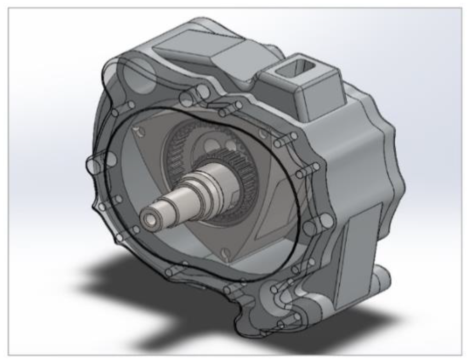
The CFD model in the presented study represents the Wankel test engine that was supplied by LENTATEK (Ankara, Turkey). The test engine is a naturally aspirated, single-rotor four-stroke rotary engine. Demonstrations of the dissembled Wankel test engine, which is in the Internal Combustion Engines Laboratory of Bursa Uludag University, are presented in Figure 1. The CAD model of the test engine is shown in Figure 2.
A summary of the gasoline-fueled, air/oil-cooled test engine specifications is listed in Table 1. Generating radius and k-factor, in Table 1, are calculated as Rg = R + a and k = (Rg)/e, respectively [40]. The compression ratio of the test engine is 9.6. Double spark plugs, with 1 mm sphere radius, are positioned at the minor axis of the test engine.

2.2. Boundary and Initial Conditions

In this study, two cases fueled with hydrogen-enriched port injected gasoline and port-injected neat gasoline-fueled cases have been investigated numerically. The hydrogen mass fraction in the intake is 0% in Case A, which is a neat gasoline-fueled case. On the other hand, hydrogen mass fractions are 5% and 10% for Case B and Case C, respectively.
The ambient temperature and pressure of these simulations are adjusted for sea level conditions. The temperature of the rotor and housing walls are set to 488 K and 443 K, respectively. The engine is set to be in full-load condition. Simulations have been carried out at 6000 rpm engine speed.
Since the purpose is to investigate the influence of hydrogen enrichment on combustion and emissions, all engine operation parameters are kept the same except for the fuel content in the mixture. It is supposed that the air/fuel mixture is homogeneous, and the fuel has completely evaporated. Some operating parameters and boundary conditions of the reference test engine are shown in Table 2.
For this study, hydrogen input is adjusted according to the hydrogen mass fraction in the intake. The hydrogen mass fraction in the mixture varies from 0% to 10% in the simulations. Mass flow rates and mass fractions of the iso-octane and hydrogen in the mixture of the simulated cases are presented in Table 3.
For all cases, hydrogen and iso-octane have been assumed to be mixed perfectly before the intake phase. The mixture has been kept at stoichiometric conditions ( λ = 1) in the simulations. Air mass fraction is adjusted as 0.9377 (the mass fraction of O2 and N2 are 0.2185 and 0.7192, respectively) in all three cases. Fuel mass fraction is adjusted as 0.0623 (C8H18 and H2 are 0.0623 and 0.0000 for Case A; 0.0592 and 0.0031 for Case B; and 0.0560 and 0.0063 for case C.), as seen in Table 3.
Air–fuel ratio of the iso-octane, hydrogen and air mixture can be calculated as [15,23,41]:
λ = m ˙ air / m ˙ C 8 H 18 · A F s t , C 8 H 18 + m ˙ H 2 A F s t , H 2
where m ˙ C 8 H 18 ,   m ˙ H 2   and   m ˙ a i r are mass flow rates (kg/h) of iso-octane, hydrogen and air, respectively. A F s t , C 8 H 18 and A F s t , H 2 represent the stoichiometric air-to-fuel ratios of iso-octane and hydrogen ( A F s t , C 8 H 18 = 14.7 and A F s t , H 2 = 34.3 ).
The energy contribution of hydrogen in the total intake charge is defined as energy fraction and calculated as follows:
H 2 % = m ˙ H 2 ·   L V H H 2 m ˙ C 8 H 18 ·   L V H C 8 H 18 + m ˙ H 2 ·   L V H H 2 × 100
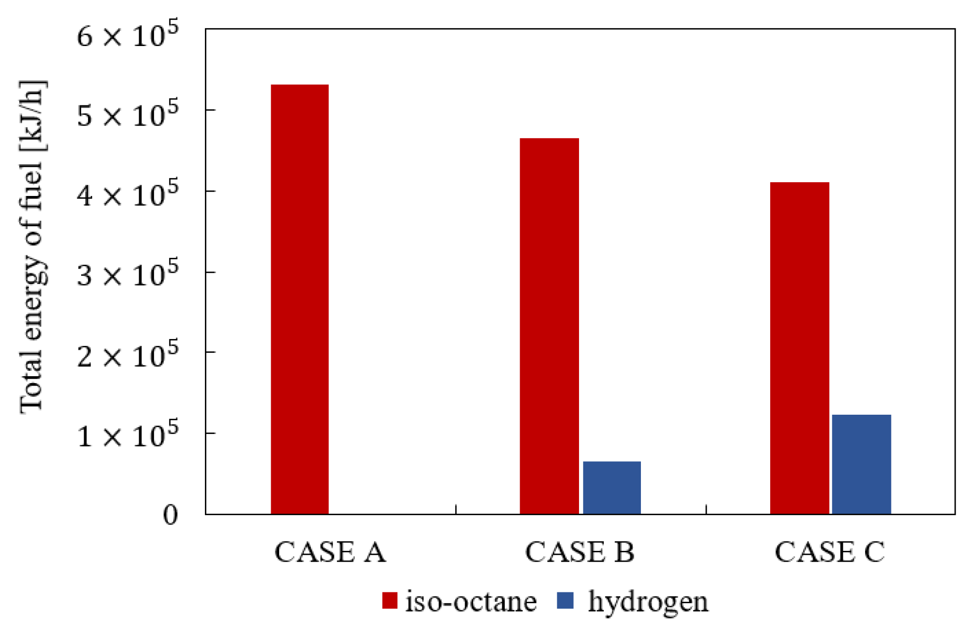
where L H V C 8 H 18 and L H V H 2 represent lower heating value (MJ/kg) of iso-octane and hydrogen, respectively ( L H V C 8 H 18 = 44.651 MJ/kg and L H V H 2 = 120.1 MJ/kg). Energy fractions of hydrogen and iso-octane in the mixture used in the CFD simulations are shown in Figure 3.

2.3. Modelling Procedure

Numerical simulations in this study have been performed using commercial software CONVERGE CFD, version 3.0.19 (Convergent Science Corp., Madison, WI, USA) [42]. The main steps of the simulation are illustrated in the flow chart in Figure 4.
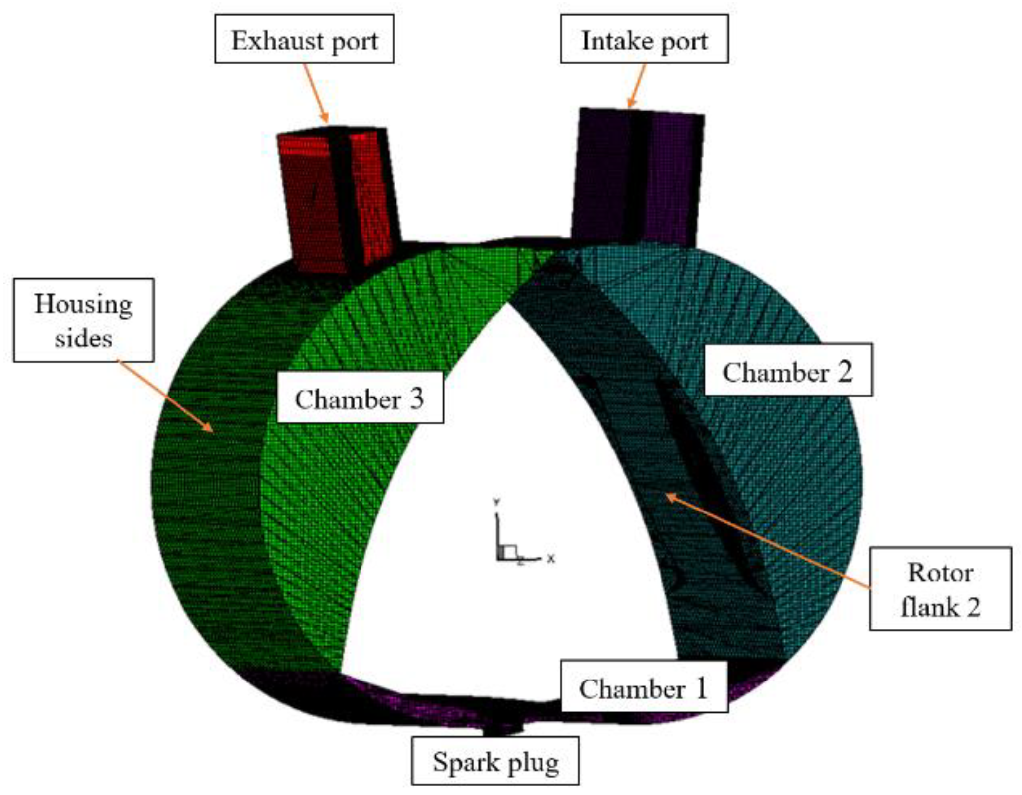
The fluid domain of the reference engine has been extracted and imported to the CONVERGE CFD as a surface file. The schematic of the test engine surfaces is illustrated in Figure 5.
In the simulations, PISO (Pressure-Implicit with Splitting of Operators), based on the predictor-corrector approach, has been chosen as a pressure–velocity coupling algorithm [29,34]. The combustion region is defined in the CFD model because of the great temperature and pressure variations between the combustion chambers. The solution algorithm of the transport equations is especially important to configure the simulation parameters. The modified PISO algorithm begins with a predictor step where the momentum equation is solved. A pressure equation is derived and solved, which leads to a correction to the momentum equation. This process of correcting and re-solving the momentum equation can be repeated as many times as necessary to attain the specified convergence. After the momentum predictor and first corrector step have been completed, the other transport equations are solved in series [42,43,44].
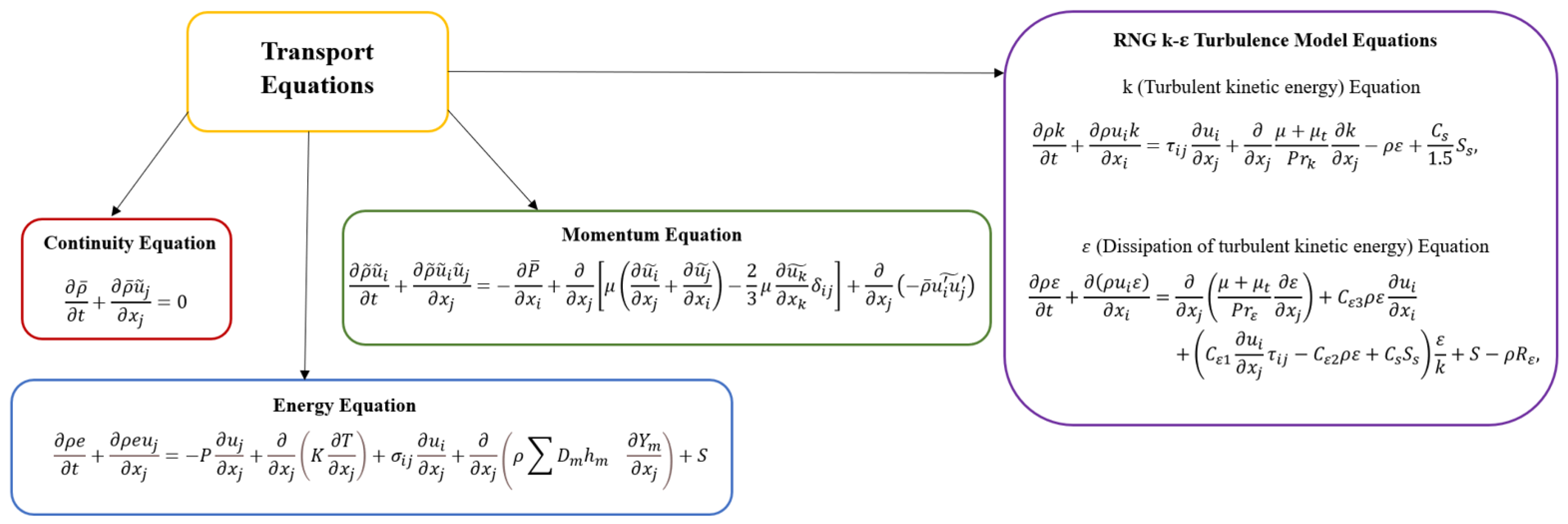
It is necessary to select a suitable turbulence model to simulate the in-cylinder flow field of rotary engines more accurately [37]. Turbulence is modeled by utilizing the RNG k-ε model in numerical calculations. The RNG k-ε model can calculate the turbulent viscosity with the values of k and ε to obtain accurate information on the position of the flow field [38]. Due to its effectiveness and high accuracy for swirling flows, the RNG k-ε model is very suitable for usage in rotary engine simulations [10,45]. In addition, the RNG k-ε model is consistent with the experimental data in terms of velocity and rotational flow location [46]. RNG k-ε equations used in the transport equations are presented in Figure 6.
In the simulations, the SAGE (Detailed chemical kinetics solver) model has been used because it is a general combustion model, which solves the chemical reaction equations during the combustion process in detail. The used SAGE model is based on work by Senecal et al. [47] and it includes adaptive zoning. When a SAGE simulation includes adaptive zoning, the chemistry cells are grouped into zones and Converge CFD solves chemistry once per zone rather than once per cell.
Since in Wankel engines there are large temperature and pressure variances between each chamber, the combustion region definition method is preferred along with CVODES with a preconditioned iterative solver (which is integrated into the program packages). The chemical reaction equations are defined in CHEMKIN format. The reaction mechanism is given as a set of elementary equations to depict a general chemical reaction in detail. The combustion of different fuels can be modeled by changing the reaction mechanism. For the analysis of the presented study, the single-component fuel isooctane (IC8H18) has been used. This fuel comprises 69 individual reaction equations and is frequently used in simulations representative of gasoline. The reaction mechanism was published and validated in the study of Jia et al. [48]. As a simplification in the present paper, the air/fuel mixture is assumed to be homogeneous; and the fuel evaporates completely in the calculations. Sub-models of the simulation are listed in Table 3 and surfaces of the simulated Wankel engine were prepared, as seen in Figure 3.
As for emission models, the Hiroyasu soot model coupling with the Nagle and Strickland-Constable is chosen to simulate soot oxidation and the Extended Zeldovich model is preferred to simulate NOx formation [42]. Sub-models of the simulation are listed in Table 4.

2.4. Mesh Independency and CFD Model Validation

Grid generation is automatically performed by CONVERGE CFD at run-time during simulation [49]. In the grid generation process, the computational domain is re-meshed for moving boundaries at each time step. In this study, the modified cut-cell Cartesian technique has been applied to the existing Wankel engine model for grid generation.
In the existing CFD model, the adaptive mesh refinement (AMR) method has been used in regions with turbulent flame front gradients and high species concentration. The fixed embedding method with an embedding level of 3 is used on the surfaces of rotor blades, housing and spark plugs. AMR technique controls the mesh size based on fluctuating and moving conditions such as species, velocity, or temperature and the fixed embedding technique refines the mesh structures at critical locations in the domain [42]. It is particularly important to use the appropriate mesh size and method in the CFD model for achieving a better resolution of velocity and temperature gradients, thereby improving the simulation accuracy and computational cost. Meshed domains of the CFD model are illustrated in Figure 7 and a mesh independence test has been performed for the base test engine (neat gasoline-fueled engine).
Four mesh structures named “coarse, medium, fine and finer” are tested, as shown in Figure 8. These mesh structures have been established with a base mesh size of 4 mm, 3 mm, 2 mm and 1 mm, respectively. AMR and fixed embedding techniques have also been applied to all the mesh structures. Indeed, the operating conditions of all mesh structures were the same except for the grid size.
In-cylinder pressures and HRR plots of the four mesh structures were compared in Figure 8a,b. Considering computational cost and simulation accuracy, the mesh structure of “fine” was chosen for the simulation.
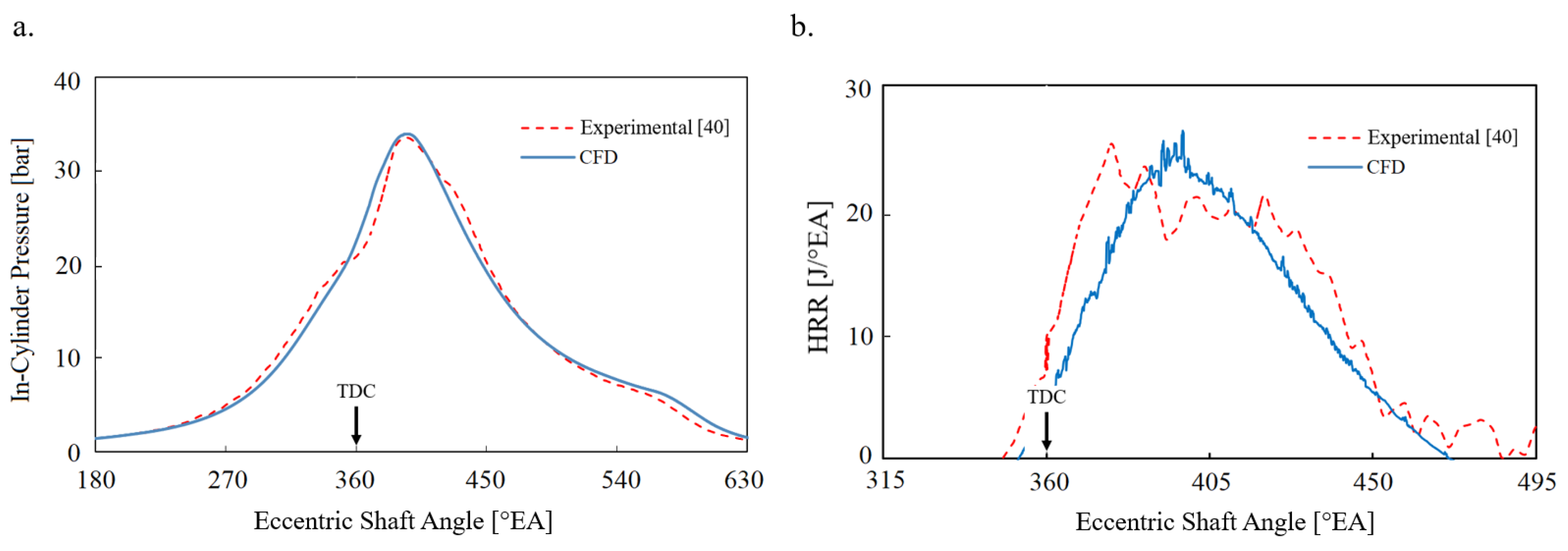
In-cylinder pressure and heat release rate (HRR) results of the simulations were compared with the experimental results of Spreitzer et al. [40]. As seen in Figure 9a,b, the pressure and HRR results of the simulations, conducted at 6000 rpm, have a good consistency. Therefore, the CFD model is considered well-calibrated.

3. Results and Discussion

3.1. Combustion Analysis

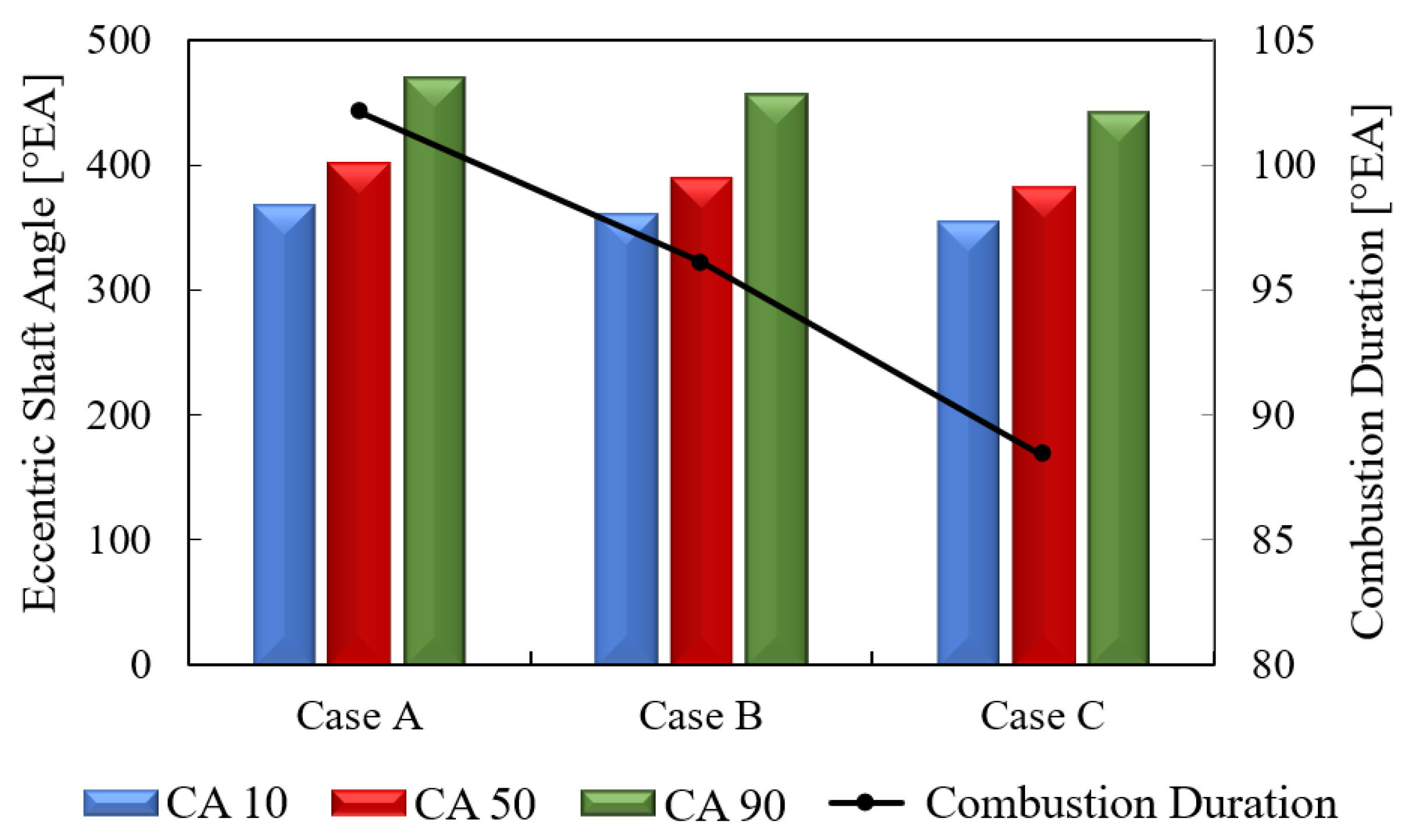
The neat gasoline-fueled Wankel engine case (Case A) is assumed as a baseline case and the results of other cases are compared with this case. Simulations have been conducted using a full engine geometry with three combustion chambers. On the other hand, chamber two is selected as a working chamber and only its results are discussed in this section to avoid repetition. The top dead center (TDC) of the working chamber is 360 °EA. Flame development period and combustion durations are important indicators of the combustion quality of a Wankel engine working chamber [50]. It is stated in the literature that for a given ignition timing, hydrogen enrichment has the advantage of shortening the flame development period and combustion duration [23]. Variations in the combustion durations, CA 10, CA 50 and CA 90 for different cases are shown in Figure 10 to investigate the effects of the hydrogen addition to the reference Wankel engine on these periods. Here, CA 10, CA 50 and CA 90 represent the eccentric shaft angle when the fuel mass burning rate reaches 10%, 50% and 90%, respectively. CA 0 indicates the ignition timing, and it has been kept the same (31 °EA) for all simulations. The periods from CA 0 to CA 10 and from CA 10 to CA 90 are named as flame development periods and combustion durations, respectively. It is clear from Figure 10 that the flame development period (CA 0-10) of the neat gasoline-fueled case (Case A) during the cycle is 367.04 °EA and CA 0-10 is decreased by 7.93 °EA and 13.78 °EA in the hydrogen blended cases, in Case B and Case C, compared Case A, respectively. The flame development period of the combustible mixture is mainly affected by the related ignition energy and homogeneity of the mixture [13,51]. Improving the ignitability and homogeneity of the mixture is very beneficial to shorten the flame development period. The presence of a highly reactive fuel [30,31], such as hydrogen with low ignition energy, in the mixture, improves the flammability of the mixture. Moreover, another factor that reduces the flame development period in a hydrogen-enriched Wankel engine is the reduction of homogeneity fluctuation caused by irregular shape deformation in the combustion chamber, rotor compression and crushing, thanks to the high molecular diffusion coefficient of hydrogen [28,52]. Furthermore, the high diffusivity and ignitability and the low flammability limit of the hydrogen improve the combustion by shortening flame development and propagation of the hydrogen-enriched cases.
CA 90 of Case A during the cycle is 469.18 °EA and this value is advanced by 13.98 °EA and 27.56 °EA in Case B and Case C, respectively. These results demonstrate that the combustion duration in the working chamber is shortened as the amount of hydrogen in the mixture increases. Although the same ignition timing has been adopted in all cases, hydrogen-blended cases with the early ignition of the mixture (reduced CA 0-10) and advanced ending of combustion have shorter combustion durations compared to neat gasoline cases. CA 10-90 of Case B and C are shortened by 6.06 °EA and 13.77 °EA, respectively, compared to that of Case A. This is mainly because the CA 10-90 of the mixture is influenced by gasoline and hydrogen flame speeds. Since the flame propagation velocity of hydrogen is very high, increasing the hydrogen fraction in the total mixture favorably facilitates the combustion rate of the original mixture (gasoline–air mixture in Case A). Enhanced concentration of O, H and OH radicals in the mixture after the hydrogen addition accelerates chemical reaction rate and combustion velocity, hence reducing the combustion duration. Other important parameters that shorten the combustion duration are the turbulent combustion process and flame surface density, which are promoted by the hydrogen addition [26,29,53].
Figure 11 shows the variations of the working chamber pressure and temperature, HRR and the total fuel mass of the simulated cases according to the eccentric shaft angle. It is obvious from Figure 11a that the peak pressure in the working chamber is obtained earlier and is closer to the TDC in the hydrogen-enriched cases compared to the neat gasoline-fueled engine case. After reaching the peak pressure value, pressure drops more rapidly in the hydrogen-enriched cases than in the neat gasoline case. This trend in the pressure curves (Figure 11a) shows that the combustion duration and post-ignition temperature are decreased with hydrogen enrichment. This is partly because hydrogen has higher diffusivity, heating value and flame speed than gasoline as a fuel. On the other hand, the maximum pressure value in the working chamber increases as the hydrogen content in the mixture increases. According to Figure 11a, the maximum pressure of the working chamber increases by 10.81% and 18.91% for Case B and Case C, respectively, compared to Case A. Hydrogen enrichment makes the air/fuel mixture more homogenous and increases laminar burning velocity [15,32]. Hence, the maximum pressure value in the working chamber increases as the hydrogen content in the mixture increases.
The crescent-shaped, narrow, and long geometry of the Wankel engine working chamber hinders heat utility and worsens heat losses. Therefore, reducing the heat loss effect during combustion in the working chamber plays a very important role in the Wankel engine performance. Heat losses during the combustion process are reduced and combustion takes place as if it is an ideal constant volume heat release when hydrogen enrichment is applied to a Wankel engine. The significant properties of hydrogen such as high diffusion rate, high homogeneity, high flame speed and large flammability, allow hydrogen-blended mixtures to have a complete, stable and fast combustion process [30,32]. Thus, heat losses cannot compete with the heat produced by the combustion process in the hydrogen-enriched Wankel engine. Therefore, working chamber temperature and HRR are higher in hydrogen-enriched cases than in neat gasoline-fueled cases, as seen in Figure 11b,c, respectively. It is seen from Figure 11b maximum working chamber temperature and HRR increase depending on the hydrogen mass fraction in the mixture. The peak values of the parameters are obtained earlier and are closer to the TDC in the hydrogen-enriched cases compared to the neat gasoline-fueled engine case. Figure 11d reveals the total mass of C8H18 in the working chamber. After the ignition, the mass of unburned C8H18 drops rapidly due to the combustion process. It can be concluded that the fuel burning rate increases as the amount of hydrogen added to the working chamber increases. Judging by the interval during which the combustion process took place, indicated by dashed lines in Figure 11d, the total mass of C8H18 started to decrease in Case C, Case B and finally Case A, respectively. The slope of the lines in this interval also showed that combustion duration in the working chamber is shortened due to the reduced flame development period and advanced the ending of combustion at hydrogen-enriched cases.
Temperature distributions of the simulated cases are given in Figure 12. This figure shows that the flame can easily expand towards the side walls of the housing in the hydrogen-blended cases. Significant properties of hydrogen such as high diffusion rate, high homogeneity and large flammability allow hydrogen blended mixtures to expand towards the narrower gaps of the working chamber.
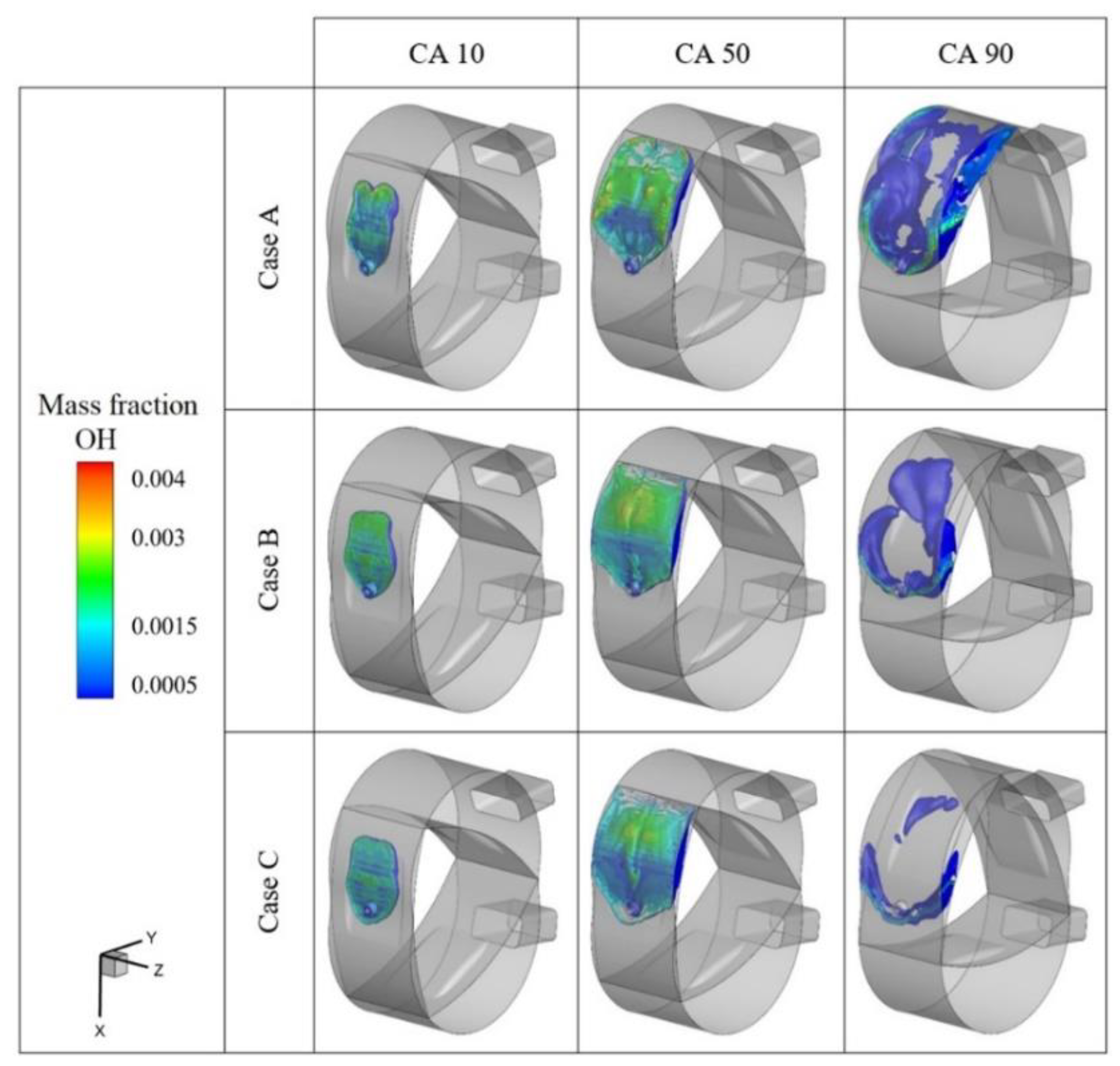
OH is a product that occurs in the second stage of the formation of luminous products during combustion and is produced in greater amounts at higher temperatures [23,54]. Therefore, the flame propagation process can be analyzed based on the variation in OH concentration [55]. Iso-surfaces of the OH mass fraction distribution of the simulated cases is given in Figure 13 to investigate flame propagation behavior in the working chamber.
According to Figure 13, faster flame propagation is obtained from hydrogen-enriched cases than from neat gasoline cases. This is mainly because hydrogen has a lower quenching distance and a higher flame speed. Although cooler walls of the housing act as a heat sink, preventing complete combustion in the regions close to the wall or within the crevice in Wankel engines, hydrogen-enriched mixture flames can be propagated into the narrower gaps by low quenching distance. Therefore, previously unburnt fuel in the working chamber can attain combustion as well [15]. As seen in the CA 90 column of Figure 13, which is accepted as the end of combustion, while the amount of OH in CA 90 is still high in Case A, it is quite low in Case C. Combustion is completed sooner in Case B and Case C compared to Case A, due to the accelerated chain reactions, so do the combustion velocity and combustion durations with hydrogen enrichment.
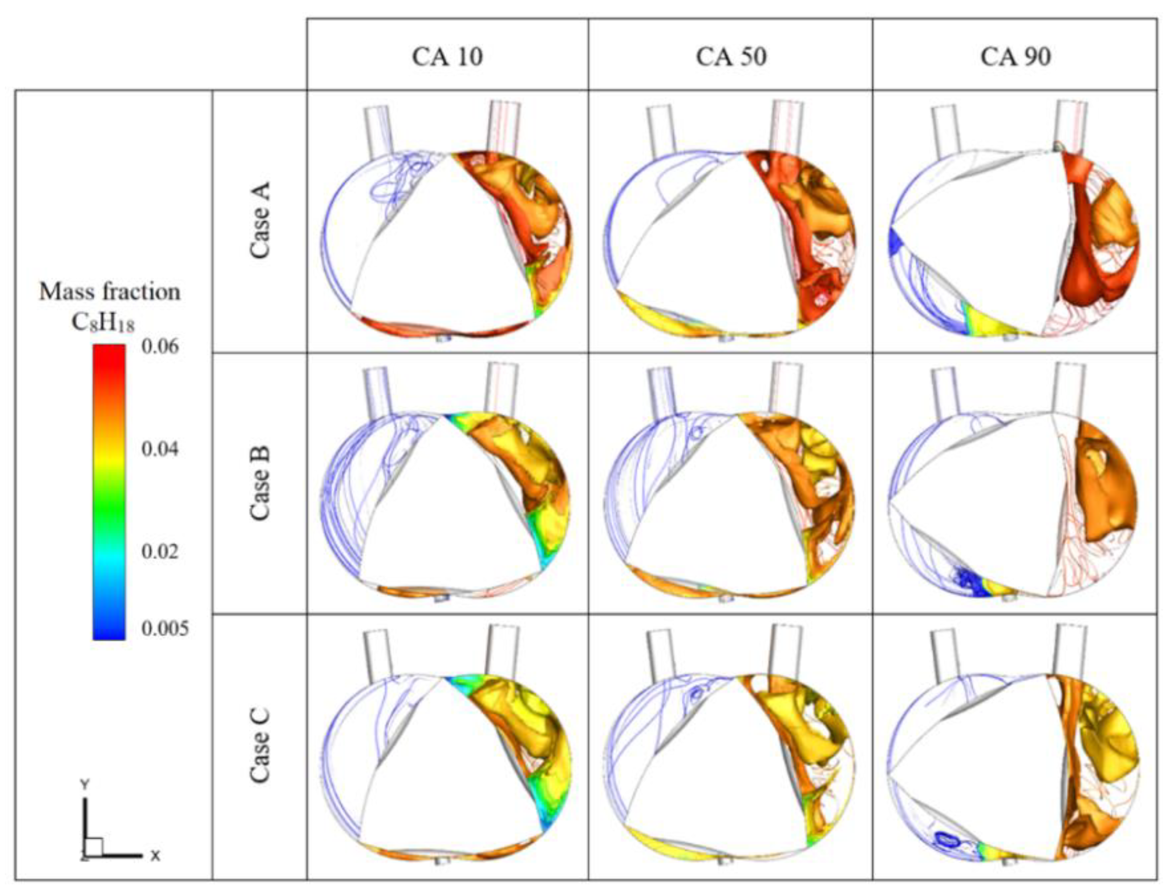
The streamlines and iso-surfaces of the C8H18 mass fraction in the combustion chamber for the presented simulations are demonstrated in Figure 14. As expected, the mass fraction of C8H18 in the working chamber of Case A is higher than in other cases because Case A has a neat gasoline charge. Owing to the accelerated fuel burning rate and shortened combustion duration with the hydrogen addition, C8H18 is depleted faster in Case B and Case C than that in Case A. As seen in the CA 90 column of Figure 14, there is still a small amount of gasoline in the leading edge of the rotor in the neat gasoline-fueled case at the end of combustion. However, gasoline near the regions of the rotor edge is depleted in the hydrogen-enriched cases. This confirms the fact that hydrogen, due to the high speed and low quenching distance of hydrogen flame, can propagate narrow and long regions in the working chamber.
Velocity magnitude distribution at the middle plane of the Wankel engine simulations is depicted in Figure 15. As seen in this figure, the main flow moves towards the leading edge of the rotor because of the squish flow and the rotation direction of the rotor in all the cases. Additionally, the spark plug is positioned at an angle towards the leading edge. Due to these reasons, the flame propagates towards the leading edge of the rotor as it can also be seen in Figure 12 and Figure 13. Main flow velocity increases with the charge in the intake process. The maximum value of the flow velocity in the working chamber occurs in the compression stroke and it decreases during the expansion stroke as the working chamber volume expands. Since the emissions are lower in the hydrogen blended cases, the flow velocity in the exhaust port decreases as the mass fraction of H2 increases.

3.2. Engine Performance

Wankel type rotary engines have less friction loss due to the absence of reciprocating mass, so the total power of Wankel engines is higher than piston engines. In addition, charging efficiency is quite high compared to reciprocating engines since they do not have intake and exhaust valves and their intake and exhaust strokes are longer. Since hydrogen has satisfactory combustion characteristics, as mentioned before better indicated torque, can be obtained from hydrogen-enriched Wankel engines. This advantage of hydrogen-enrichment applications is very useful for operating at high engine speeds where a short combustion duration is desired.
The Wankel engine suffers from the quenching phenomenon which causes higher squish flow due to the rotor housing interface. The addiction of hydrogen accelerates the burning process of fuel. This increased burning speed contributes to a stronger squish flow, resulting in better performance output even at high engine operating speeds. It can be concluded that hydrogen enrichment increases the existing neat gasoline engine performance.
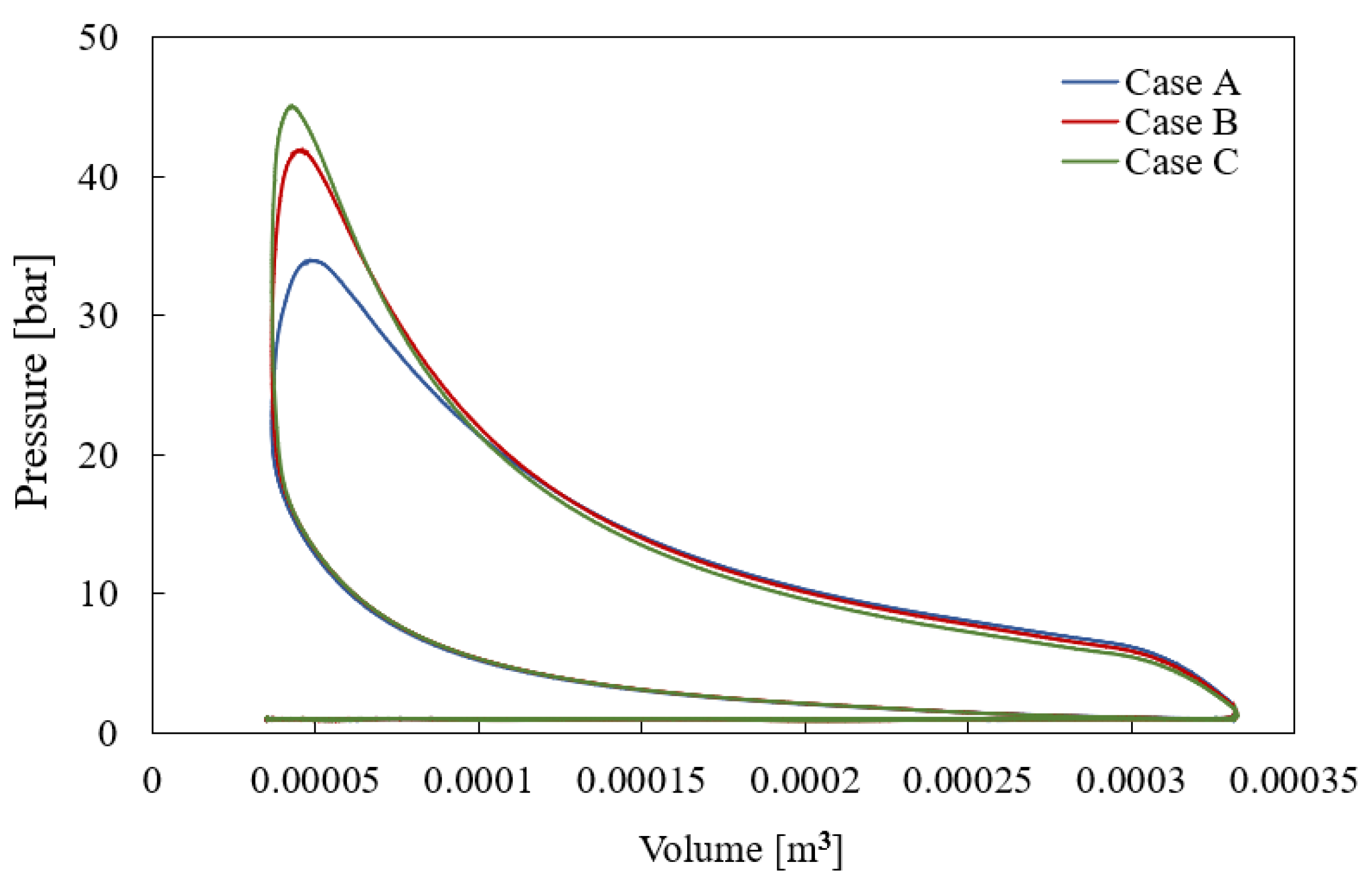
Indicated work can be calculated from the crossing area of the P-V diagram and it is frequently used to evaluate engine performance. In Figure 16, indicated work values of the simulated cases are compared to each other. This figure shows that the highest indicated work is obtained from Case C.
Performance parameters of the presented simulations are compared in Figure 17. The gross IMEP, indicated torque and indicated power increase, despite the decrease in the total fuel consumption with the amount of hydrogen added to the mixture (Figure 17a,b). Compared with the simulation results of the neat gasoline-fueled engine case (Case A), IMEP increased by 8.18% and 9.68% in Case B and Case C, respectively. Indicated torque values of Case B and Case C are increased by 6.15% and 7.99%, respectively, according to that of Case A. The percentage of indicated power value increase in Case B and Case C relative to Case A is almost the same as the indicated torque increase percentage.

3.3. Emissions

Thanks to the considerable properties of hydrogen [36,56,57], the mixture of the hydrogen-blended Wankel engine can be burned easier even in the narrow regions of the working chamber. The mass fraction of soot, NOx, CO and CO2, at the working chamber of presented simulations are plotted against eccentric shaft angle in Figure 18. These emission values are obtained from the exhaust port opening time (566 °EA), indicated by the dashed lines in this figure.
Soot mass fractions for Case B and Case C are decreased by 11.92% and 20.06%, respectively, compared to Case A (Figure 18a). Because soot production depends on the working chamber temperature. On the contrary, NOx emissions increase approximately 1 time in Case B and increase slightly more than 2 times in Case C, compared to Case A as illustrated in Figure 18b. Increasing working chamber pressure and temperature, in the hydrogen-enriched Wankel engine cases as depicted in Figure 11a,b, stimulate thermal NOx formation. As for CO and CO2 emissions of the presented cases, CO mass fractions are reduced by 33.35% and 46.20%. Similarly, CO2 mass fractions are reduced by 33.35% and 46.20% for Case B and Case C compared to Case A (Figure 18c,d). This is mainly because CO is converted into CO2 by oxidation reactions in the entire combustion process and it is consumed through the reaction of CO + OH⇌CO2 + H [37,58]. OH radicals would be taken away by H and bound in H2O, which leads to higher CO content. Maximum working chamber temperature increases with hydrogen addition and the oxidation reaction of CO into CO2 is stimulated. In addition to this, the hydrogen-enriched cases have lower carbon contents because the gasoline is partly replaced by hydrogen atoms, thus exhausts of these cases have less carbonaceous emissions than neat gasoline-fueled engines.

3.4. Discussion

The promising potential of the hydrogen enrichment strategy in Wankel engines is presented in this study. The results can also be discussed in terms of the use of hydrogen enrichment techniques in UAV applications of the Wankel engine, where combustion, performance characteristics and emissions deteriorate with the increase in altitude. Hydrogen enrichment contributes to improving combustion in the working chamber as mentioned above. In addition, the quenching problem, which is the main problem of Wankel engines for UAV applications due to the colder operating conditions at high altitudes, can be eliminated by hydrogen addition. Therefore, it can be inferred that hydrogen enrichment is a very useful solution for improving the performance of the Wankel engine for UAVs. As for emissions, the only disadvantage of the hydrogen addition strategy in terms of emissions is the increase in NOx emissions. However, NOx emissions of the hydrogen-enriched Wankel engine, operating at high altitudes, would be lower due to cooler operating conditions than at sea level. On the other hand, there is an increase in soot, CO and CO2 emissions of a neat gasoline-fueled Wankel engine due to worsening combustion as the altitude increases. When hydrogen enrichment is applied to the Wankel engine, there will be less soot CO and CO2 emissions at high altitudes due to the improved combustion performance compared to the neat gasoline-fueled engine.

4. Conclusions

This study investigated the effectiveness of the hydrogen enrichment strategy in a gasoline-fueled Wankel engine. Simulations have been performed using experimentally validated full-engine models. The Wankel engine has a special geometry and there are some interactions between the sequential chambers. Using a full-engine model, with three chambers, helps show the effects of the hydrogen addition approach on combustion characteristics in the entire engine more accurately. This study demonstrates the considerable potential of hydrogen enrichment to increase engine performance and reduce emissions of a Wankel engine.
The main findings of this study are listed below:
  • The significant properties of hydrogen such as high homogeneity and diffusivity, fast flame propagation and large flammability enable hydrogen blended mixtures to have a more stable and complete combustion process. Moreover, increasing the concentration of O, H and OH radicals during the combustion process after the hydrogen addition increases combustion velocity and shortens combustion durations. Hence, heat losses during the combustion process can be reduced. In addition, pressure, temperature and HRR values in the working chamber are higher and the peak values of these parameters are obtained earlier and are closer to the TDC in hydrogen-blended cases compared to the neat gasoline-fueled case. Additionally, hydrogen-blended mixture flames can be propagated into the narrower gaps by the low quenching distance of hydrogen. Despite the geometric limitations of Wankel engines, it can be concluded that the hydrogen enrichment technique is quite advantageous for Wankel engines in terms of combustion performance.
  • The quenching phenomenon of Wankel engines, which leads to higher squish flow due to the rotor housing interface, can be minimized with the hydrogen enrichment approach. Because increasing the burning speed with hydrogen addition contributes to obtaining a stronger squish flow. Thus, the performance characteristics of the Wankel engine increase with hydrogen enrichment. For a fixed ignition timing, IMEP, indicated torque and indicated power improved, despite the decrease in total fuel consumption of the hydrogen blended cases with the amount of hydrogen added. If the ignition timings are optimized based on the new ignition delay periods, it is feasible to enhance the engine performance of fuel mixtures.
  • As the hydrogen content of the mixture increases, engine instability and soot, CO and CO2 emissions are reduced. The main reason for this is the increasing working chamber pressure and temperature with hydrogen addition. On the other hand, thermal NOx formation is also increased due to the higher operating temperature of the hydrogen-enriched cases.

5. Future Work

The benefits of the hydrogen enrichment strategy in the Wankel engine will be improved further by optimizing spark plug ignition timing and spark plug positions in future studies. Moreover, the hydrogen direct injection technique will be applied to the full-engine CFD model to improve the mixture formation and combustion process. In addition, the hydrogen addition strategy effectiveness in the Wankel engine for UAV applications will be investigated by simulating the hydrogen-enriched Wankel engine simulations at different altitude conditions.

Author Contributions

Conceptualization, M.K., A.S. and R.S.; methodology, M.K.; software, M.K.; validation, M.K.; writing—original draft preparation, M.K.; writing—review and editing, M.K., A.S. and R.S.; supervision, A.S. and R.S. All authors have read and agreed to the published version of the manuscript.

Funding

This research received no external funding.

Data Availability Statement

Not applicable.

Acknowledgments

The authors thank LENTATEK for their donation of the Wankel research engine, Bursa Technical University High-Performance Computing Laboratory and Bursa Uludag University Internal Combustion Engine Laboratory for their technical support and Convergent Science Inc. for providing the Converge license.

Conflicts of Interest

The authors declare no conflict of interest. The funders had no role in the design of the study; in the collection, analyses, or interpretation of data; in the writing of the manuscript; or in the decision to publish the results.

Nomenclature

AF st , C 8 H 18 Stoichiometric air-to-fuel ratio of iso-octane
AF st , H 2 Stoichiometric air-to-fuel ratio of hydrogen
CAEccentric shaft angle
CA 10Eccentric shaft angle where the fuel mass burning rate reached 10% (°EA)
CA 50Eccentric shaft angle where the fuel mass burning rate reached 50% (°EA)
CA 10-90Eccentric shaft angle duration from 10% to 90% mass burning rate of the total fuel (°EA)
HRRHeat release rate (J/°EA)
IMEPIndicated mean effective pressure (bar)
rpmRotation per minutes
TDCTop dead center
λ Excess air ratio
n C 8 H 18 and n H 2 Molar coefficients of C 8 H 18 and   H 2
m C 8 H 18 and m H 2 Mass fractions of C 8 H 18 and H 2

References

  1. Cihan, O.; Doğan, H.E.; Kutlar, O.A.; Demirci, A.; Javadzadehkalkhoran, M. Evaluation of heat release and combustion analysis in spark ignition Wankel and reciprocating engine. Fuel 2020, 261, 116479. [Google Scholar] [CrossRef]
  2. Ji, C.; Wang, H.; Shi, C.; Wang, S.; Yang, J. Multi-objective optimization of operating parameters for a gasoline Wankel rotary engine by hydrogen enrichment. Energy Convers. Manag. 2021, 229, 113732. [Google Scholar] [CrossRef]
  3. Meng, H.; Ji, C.; Wang, S.; Wang, D.; Yang, J. Optimizing the idle performance of an n-butanol fueled Wankel rotary engine by hydrogen addition. Fuel 2021, 288, 119614. [Google Scholar] [CrossRef]
  4. Pillai, K.M.; Mithran, A.J.; Grips, V.K.W.; Kumar, K.; Sinha, U.K.; Varadarajan, M.N.; Isaac, J.J.; Murthy, Y.V.S. Design and Development of an Indigenous 55 Hp Wankel Engine. In Proceedings of the International Conference on Aerospace Science and Technology, Bangalore, India, 26–28 June 2008. [Google Scholar]
  5. Kweon, C.M. A Review of Heavy-Fueled Rotary Engine Combustion Technologies; Technical Report, ARL-TR-5546; Army Research Laboratory: Aberdeen Proving Ground, MD, USA, 2011; Available online: https://apps.dtic.mil/sti/pdfs/ADA545309.pdf (accessed on 5 December 2022).
  6. Tartakovsky, L.; Baibikov, V.; Gutman, M.; Veinblat, M.; Reif, J. Simulation of Wankel Engine Performance Using Commercial Software for Piston Engines; SAE Technical Paper; SAE: Warrendale, PA, USA, 2012. [Google Scholar] [CrossRef] [Green Version]
  7. Pisnoy, S.; Tartakovsky, L. Numerical Investigation of the combined influence of three-plug arrangement and slot positioning on Wankel engine performance. Energies 2021, 14, 1130. [Google Scholar] [CrossRef]
  8. Leboeuf, M.; Dufault, J.F.; Nickerson, M.; Becker, K. Performance of a Low-Blowby Sealing System for a High Efficiency Rotary Engine; SAE Technical Paper; SAE: Warrendale, PA, USA, 2018. [Google Scholar] [CrossRef]
  9. Kutlar, O.A.; Malkaz, F. Two-stroke Wankel type rotary engine: A new approach for higher power density. Energies 2019, 12, 4096. [Google Scholar] [CrossRef] [Green Version]
  10. Finkelberg, L.; Kostuchenkov, A.; Zelentsov, A.; Minin, V. Improvement of combustion process of spark-ignited aviation Wankel engine. Energies 2019, 12, 2292. [Google Scholar] [CrossRef] [Green Version]
  11. Boughou, S.; Mohiuddin, A.K.M. Combustion chamber design effect on the rotary engine performance- A review. Int. J. Automot. Eng. 2020, 11, 200–212. [Google Scholar] [CrossRef]
  12. Zhang, Y.; Zuo, Z.; Liu, J.; Stewart, P.; Bingham, C. Numerical analysis on combustion characteristic of leaf spring rotary engine. Energies 2015, 8, 8086–8109. [Google Scholar] [CrossRef]
  13. Su, T.; Ji, C.; Wang, S.; Shi, L.; Yang, J.; Cong, X. Effect of spark timing on performance of a hydrogen-gasoline rotary engine. Energy Convers. Manag. 2017, 148, 120–127. [Google Scholar] [CrossRef]
  14. Amrouche, F.; Erickson, P.A.; Park, J.W.; Varnhagen, S. Extending the lean operation limit of a gasoline Wankel rotary engine using hydrogen enrichment. Int. J. Hydrogen Energy 2016, 41, 14261–14271. [Google Scholar] [CrossRef]
  15. Amrouche, F.; Erickson, P.A.; Park, J.W.; Varnhagen, S. An experimental study of a hydrogen-enriched ethanol fueled Wankel rotary engine at ultra lean and full load conditions. Energy Convers. Manag. 2016, 123, 174–184. [Google Scholar] [CrossRef]
  16. Fan, B.; Pan, J.; Yang., W.; Liu., Y.; Bani, S.; Chen, W. Numerical investigation of the effect of injection strategy on mixture formation and combustion process in a port injection natural gas rotary engine. Energy Convers. Manag. 2017, 123, 511–523. [Google Scholar] [CrossRef]
  17. Su, T.; Ji, C.; Wang, S.; Cong, X.; Shi, L.; Yang, J. Improving the lean performance of an n-butanol rotary engine by hydrogen enrichment. Energy Convers. Manag. 2018, 157, 96–102. [Google Scholar] [CrossRef]
  18. Fan, B.; Pan, J.; Yang, W.; Chen, W.; Bani, S. The influence of injection strategy on mixture formation and combustion process in a direct injection natural gas rotary engine. Appl. Energy 2017, 187, 663–674. [Google Scholar] [CrossRef]
  19. Ji, C.; Chang, J.; Wang, S.; Yang, J.; Wang, D.; Cheng, S.; Ma, Z.; Zhang, B. Numerical study of hydrogen direct injection strategy on mixture formation and combustion process in a partially premixed gasoline Wankel rotary engine. Energy Convers. Manag. 2018, 176, 184–193. [Google Scholar] [CrossRef]
  20. Fan, B.W.; Pan, J.F.; Pan, Z.H.; Tang, A.K.; Zhu, Y.J.; Xue, H. Effects of pocket shape and ignition slot locations on the combustion processes of a rotary engine fueled with natural gas. Appl. Therm. Eng. 2015, 89, 11–27. [Google Scholar] [CrossRef]
  21. Yang, J.; Ji, C.; Wang, S.; Wang, D.; Ma, Z.; Ma, L. A comparative study of mixture formation and combustion processes in a gasoline Wankel rotary engine with hydrogen port and direct injection enrichment. Energy Convers. Manag. 2018, 168, 21–31. [Google Scholar] [CrossRef]
  22. Ohkubo, M.; Tashima, S.; Shimizu, R.; Fuse, S.; Ebino, H. Developed Technologies of the New Rotary Engine (RENESIS); SAE Technical Paper; SAE: Warrendale, PA, USA, 2004. [Google Scholar] [CrossRef]
  23. Taskiran, O.O. Improving burning speed by using hydrogen enrichment and turbulent jet ignition system in a rotary engine. Int. J. Hydrogen Energy 2021, 46, 29649–29662. [Google Scholar] [CrossRef]
  24. Dhole, A.E.; Yarasu, R.B.; Lata, D.B.; Priyam, A. Effect on performance and emissions of a dual fuel diesel engine using hydrogen and producer gas as secondary fuels. Int. J. Hydrogen Energy 2014, 39, 8087–8097. [Google Scholar] [CrossRef]
  25. Dhole, A.E.; Yarasu, R.B.; Lata, D.B. Effect of hydrogen and producer gas as secondary fuels on combustion parameters of a dual fuel diesel engine. Appl. Therm. Eng. 2016, 108, 764–773. [Google Scholar] [CrossRef]
  26. Wang, J.; Huang, Z.; Tang, C.; Zheng, J. Effect of hydrogen addition on early flame growth of lean burn natural gas-air mixture. Int. J. Hydrogen Energy 2010, 35, 7246–7252. [Google Scholar] [CrossRef]
  27. Wang, J.; Huang, Z.; Zheng, J.; Miao, H. Effect of partially premixed and hydrogen addition on natural gas direct-injection lean combustion. Int. J. Hydrogen Energy 2009, 34, 9239–9247. [Google Scholar] [CrossRef]
  28. Di Sarli, V.; Di Benedetto, A.; Long, E.J.; Hargrave, G.K. Time-Resolved Particle Image Velocimetry of dynamic interactions between hydrogen-enriched methane/air premixed flames and toroidal vortex structures. Int. J. Hydrogen Energy 2012, 37, 16201–16213. [Google Scholar] [CrossRef] [Green Version]
  29. Hu, E.; Huang, Z.; Zheng, J.; Li, Q.; He, J. Numerical study on laminar burning velocity and NO formation of premixed methane-hydrogen-air flames. Int. J. Hydrogen Energy 2009, 34, 6545–6557. [Google Scholar] [CrossRef]
  30. Agreda, A.; Di Sarli, V.; Di Benedetto, A. Bifurcation analysis of the effect of hydrogen addition on the dynamic behavior of lean premixed pre-vaporized ethanol combustion. Int. J. Hydrogen Energy 2012, 37, 6922–6932. [Google Scholar] [CrossRef]
  31. Di Sarli, V. Stability and emissions of a lean pre-mixed combustor with rich catalytic/lean-burn pilot. Int. J. Chem. React. Eng. 2014, 12, 77–89. [Google Scholar] [CrossRef]
  32. Salzano, E.; Cammarota, F.; Di Benedetto, A.; Di Sarli, V. Explosion behavior of hydrogen-methane/air mixtures. J. Loss Prev. Process Ind. 2012, 25, 443–447. [Google Scholar] [CrossRef]
  33. Cammarota, F.; Di Benedetto, A.; Di Sarli, V.; Salzano, E. The effect of hydrogen addition on the explosion of ethanol/air mixtures. Chem. Eng. Trans. 2012, 26, 405–410. [Google Scholar] [CrossRef]
  34. Wang, H.; Ji, C.; Shi, C.; Wang, S.; Yang, J.; Ge, Y. Investigation of the gas injection rate shape on combustion, knock and emissions behavior of a rotary engine with hydrogen direct-injection enrichment. Int. J. Hydrogen Energy 2021, 46, 14790–14804. [Google Scholar] [CrossRef]
  35. Fan, B.; Pan, J.; Liu, Y.; Zhu, Y.; Pan, Z.; Chen, W.; Otchere, P. Effect of hydrogen injection strategies on mixture formation and combustion process in a hydrogen direct injection plus natural gas port injection rotary engine. Energy Convers. Manag. 2018, 160, 150–164. [Google Scholar] [CrossRef]
  36. Ji, C.; Su, T.; Wang, S.; Zhang, B.; Yu, M.; Cong, X. Effect of hydrogen addition on combustion and emissions performance of a gasoline rotary engine at part load and stoichiometric conditions. Energy Convers. Manag. 2016, 121, 272–280. [Google Scholar] [CrossRef]
  37. Ji, C.; Chang, K.; Wang, S.; Yang, J.; Wang, D.; Meng, H.; Wang, H. Effect of injection strategy on the mixture formation and combustion process in a gasoline direct injection rotary engine. Fuel 2021, 304, 121428. [Google Scholar] [CrossRef]
  38. Shi, C.; Ji, C.; Wang, S.; Jinxin, Y.; Huaiyu, W. Experimental and numerical study of combustion and emissions performance in a hydrogen-enriched Wankel engine at stoichiometric and lean operations. Fuel 2021, 291, 120181. [Google Scholar] [CrossRef]
  39. Zambalov, S.D.; Yakovlev, I.A.; Skripnyak, V.A. Numerical simulation of hydrogen combustion process in rotary engine with laser ignition system. Int. J. Hydrogen Energy 2017, 42, 17251–17259. [Google Scholar] [CrossRef]
  40. Spreitzer, J.; Zahradnik, F.; Geringer, B. Implementation of a Rotary Engine (Wankel Engine) in a CFD Simulation Tool with Special Emphasis on Combustion and Flow Phenomena; SAE Technical Papers; SAE: Warrendale, PA, USA, 2015. [Google Scholar] [CrossRef]
  41. Wang, S.; Ji, C.; Zhang, B. Effects of hydrogen addition and cylinder cutoff on combustion and emissions performance of a spark-ignited gasoline engine under a low operating condition. Energy 2010, 35, 4754–4760. [Google Scholar] [CrossRef]
  42. Richards, K.J.; Senecal, P.K.; Pomraning, E. Converge Manual 3.0; Convergent Science: Madison, WI, USA, 2022. [Google Scholar]
  43. Issa, R.I. Solution of the implicitly discretised fluid flow equations by operator-splitting. J. Comput. Phys. 1986, 62, 40–65. [Google Scholar] [CrossRef]
  44. Sener, R.; Yangaz, M.U.; Gul, M.Z. Effects of injection strategy and combustion chamber modification on a single-cylinder diesel engine. Fuel 2020, 266, 117122. [Google Scholar] [CrossRef]
  45. Boretti, A. Modeling Unmanned Aerial Vehicle Jet Ignition Wankel Engines with CAE/CFD. Adv. Aircr. Spacecr. Sci. 2015, 2, 445–467. [Google Scholar] [CrossRef]
  46. Sener, R.; Gül, M.Z. Optimization of the combustion chamber geometry and injection parameters on a light-duty diesel engine for emission minimization using multi-objective genetic algorithm. Fuel 2021, 304, 121379. [Google Scholar] [CrossRef]
  47. Senecal, P.K.; Pomraning, E.; Richards, K.J.; Briggs, T.E.; Choi, C.Y.; McDavid, R.M. Multi-Dimensional Modeling of Direct-Injection Diesel Spray Liquid Length and Flame Lift-off Length Using CFD and Parallel Detailed Chemistry; SAE Technical Paper; SAE: Warrendale, PA, USA, 2003. [Google Scholar] [CrossRef]
  48. Jia, M.; Xie, M.A. Chemical kinetics model of iso-octane oxidation for HCCI engines. Fuel 2006, 85, 2593–2604. [Google Scholar] [CrossRef]
  49. Bigalli, S.; Catalani, I.; Balduzzi, F.; Matteazzi, N.; Agostinelli, L.; De Luca, M.; Ferrara, G. Numerical investigation on the performance of a 4-stroke engine with different passive pre-chamber geometries using a detailed chemistry solver. Energies 2022, 15, 4968. [Google Scholar] [CrossRef]
  50. Kan, Z.; Hu, Z.; Lou, D.; Cao, Z.; Cao, J. Effect of the altitude on the combustion characteristics of a low-compression-ratio diesel engine during the start-up process. Proc. Inst. Mech. Eng. Part D J. Automob. Eng. 2017, 231, 1838–1847. [Google Scholar] [CrossRef]
  51. Heywood, J.B. Internal Combustion Engine Fundamentals; McGraw-Hill: New York, NY, USA, 1988. [Google Scholar]
  52. Norbye, J.P. Wankel Rotary Engine; Chilton Book Company: Philadelphia, PA, USA, 1971. [Google Scholar]
  53. Huang, Z.; Zhang., Y.; Zeng, K.; Liu, B.; Wang, Q.; Jiang, D. Measurements of laminar burning velocities for natural gas-hydrogen-air mixtures. Combust Flame 2006, 146, 302–311. [Google Scholar] [CrossRef]
  54. Singh, S.; Musculus, M.P.B.; Reitz, R.D. Mixing and flame structures inferred from OH-PLIF for conventional and low temperature diesel engine combustion. Combust. Flame 2009, 156, 1898–1908. [Google Scholar] [CrossRef]
  55. Zhu, H.; Duan, J. Research on emission characteristics of hydrogen fuel internal combustion engine based on more detailed mechanism. Int. J. Hydrogen Energy 2019, 44, 5592–5598. [Google Scholar] [CrossRef]
  56. Su, T.; Ji, C.; Wang, S.; Shi, L.; Yang, J.; Cong, X. Idle performance of a hydrogen/gasoline rotary engine at lean condition. Int. J. Hydrogen Energy 2017, 42, 12696–12705. [Google Scholar] [CrossRef]
  57. Su, T.; Ji, C.; Wang, S.; Shi, L.; Yang, J.; Cong, X. Improving idle performance of hydrogen-gasoline rotary engine at stoichiometric condition. Int. J. Hydrogen Energy 2017, 42, 11893–11901. [Google Scholar] [CrossRef]
  58. Li, A.; Zheng, Z.; Peng, T. Effect of Water Injection Timing on the Combustion and Emissions of a Direct Injection Gasoline Engine. Energy Technol. J. 2021, 9, 2001064. [Google Scholar] [CrossRef]
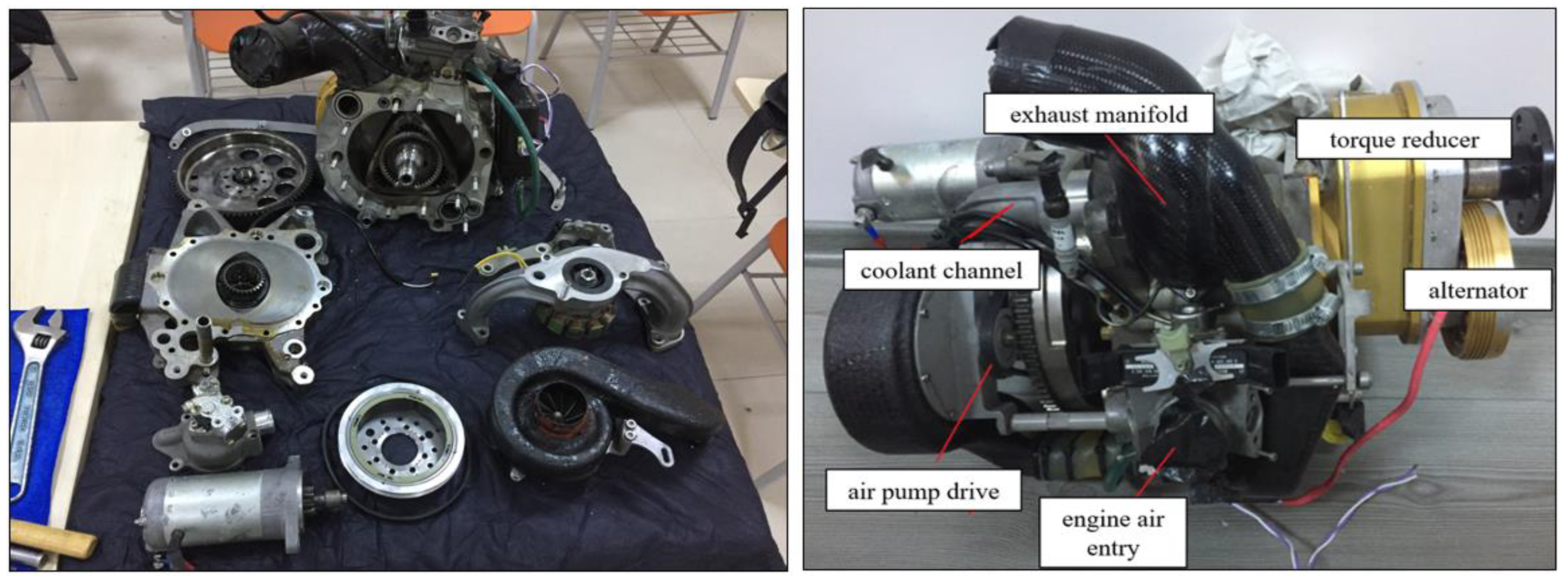
Figure 1. Demonstration of the components of the Wankel test engine and definition of some of its parts.
Energies 15 09331 g001
Figure 2. The CAD model of the Wankel Engine.
Energies 15 09331 g002
Figure 3. Energy fractions of hydrogen and iso-octane in the mixture.
Energies 15 09331 g003
Figure 4. Flow chart of the simulation process.
Energies 15 09331 g004
Figure 5. Schematic illustration of the test engine surfaces.
Energies 15 09331 g005
Figure 6. Transport equations.
Energies 15 09331 g006
Figure 7. Meshed zones of the CFD model.
Energies 15 09331 g007
Figure 8. Mesh independence study of; (a) in-cylinder pressure, (b) HRR results.
Energies 15 09331 g008
Figure 9. Validation of the CFD model with the experimental results. (a) Pressure, (b) HRR results versus eccentric shaft angle.
Energies 15 09331 g009
Figure 10. Comparison of CA 10, CA 50 and CA 90 occurrence positions and combustion duration for different cases.
Energies 15 09331 g010
Figure 11. Comparison of (a) pressure, (b) temperature, (c) HRR and (d) mass of C8H18 for different cases.
Energies 15 09331 g011
Figure 12. Temperature distribution for different cases at CA 10, CA 50 and CA 90.
Energies 15 09331 g012
Figure 13. Iso-surfaces of OH mass fraction in the combustion chamber for different cases at CA 10, CA 50 and CA 90.
Energies 15 09331 g013
Figure 14. Streamlines and iso-surfaces of C8H18 mass fraction in the Wankel engine for different cases at CA 10, CA 50 and CA 90.
Energies 15 09331 g014
Figure 15. Velocity magnitude distribution at the middle plane of the front view for different cases at CA 10, CA 50 and CA 90.
Energies 15 09331 g015
Figure 16. P-V diagram of the working chamber for different cases.
Energies 15 09331 g016
Figure 17. Comparison of performance parameters for different cases (a) indicated torque and IMEP, (b) total fuel consumption and indicated power.
Energies 15 09331 g017
Figure 18. Comparison of mass fractions of (a) OH, (b) NOx, (c) CO and (d) CO2 at the working chamber for different cases.
Energies 15 09331 g018
Table 1. Test engine specifications.
Engine TypeA Single-Rotor, Four-Stroke Wankel Engine
Radius, (R) [mm]71.89
Amount of parallel transfer of trochoid, (a) [mm]1.05
Generating Radius, ( R g )72.94
Eccentricity, (e) [mm]11.5
Width [mm]7.44
k-factor (k)6.34
InletIn the trochoid
OutletIn the trochoid
Power output35 [kW] @ 6000 rpm
Spark plug position10 mm after the minor axis
Spark plug shape/radius [mm]Sphere/1
BearingBall bearing
Rotor cooling and lubricationAir/oil mixture
Housing coolingWater
Table 2. Summary of the test engine operating parameters and boundary conditions.
SubjectInput
Compression ratio9.6
Spark plugs energy0.03 and 0.04 J
Spark plugs surface temperature625 K
Inlet air conditionsSea level conditions
Intake and exhaust portPressures boundary condition
Intake/exhaust port surface temperature323/500 K
Rotor/house wall temperature488/443 K
Rotor wallWall boundary condition
Wall boundaryNo-slip
Pressure–Velocity couplingPISO algorithm
Reaction mechanism48 species and 152 reactions
Mesh methodModified cut-cell Cartesian
Table 3. Mass flow rates and mass fractions of the fuel mixtures.
Mass Flow Rates of the Fuels
in the Mixture
Mass Fractions of the Fuels
in the Mixture
m ˙ C 8 H 18   ( kg / h ) m ˙ H 2 kg / h X C 8 H 18 X H 2
Case A11.880.000.06230.0000
Case B10.420.550.05920.0031
Case C9.181.020.05600.0063
Table 4. Sub-models of the simulation.
SubjectInput
Turbulent modelRNG k-ε
Wall modelWall heat transfer: O’Rourke and Amsden
Near wall treatment: Standard Wall Function
Combustion modelSAGE (Adaptive Zoning)
NOx modelExtended Zeldovich
Soot modelHiroyasu-NSC
Publisher’s Note: MDPI stays neutral with regard to jurisdictional claims in published maps and institutional affiliations.