Article

Performance Improvement of a Highly Loaded Transonic Centrifugal Compressor with Tandem Impeller and Freeform Blade Configuration †

1
School of Power and Energy, Northwestern Polytechnical University, Xian 710072, China
2
Institute of Engineering Thermophysics, Chinese Academy of Sciences, Beijing 100190, China
*
Author to whom correspondence should be addressed.
This paper is an extended version of our paper published in the Proceeding of Global Power and Propulsion Society, 18th–20th October, 2021, Xi’an, China.
Energies 2022, 15(24), 9283; https://doi.org/10.3390/en15249283
Submission received: 16 September 2022 / Revised: 21 November 2022 / Accepted: 27 November 2022 / Published: 7 December 2022
(This article belongs to the Section J: Thermal Management)

Abstract

:
A highly loaded transonic centrifugal compressor is aerodynamically designed and numerically investigated. The objectives are to improve the compressor efficiency by using tandem impeller configuration and 3D free-formed blade design concepts. This approach has the potential to control both the transonic and distorted flows within impeller passages. The results suggest that employing the tandem impeller configuration can significantly improve the compressor efficiency by 1.4%. The efficiency gain is mainly contributed by the improved uniformity of the impeller discharge flow achieved when the newly generated inducer-shed vortices rearrange the secondary flow pattern. In addition, the location of the impeller passage shock moves downstream due to the potential effect within the tandem impeller and locally changes the back pressure of the inducer. These factors mitigate flow losses in the impeller and diffuser. Furthermore, the 3D design concepts of forward blade sweep and negative lean are employed in the tandem impeller configuration. The forward sweep design of the inducer weakens flow acceleration before the passage shock, and the negative lean design optimizes the secondary flow pattern, which yield an additional compressor efficiency improvement of 0.7%. The study conducted in this paper provides a valuable reference for future advanced transonic centrifugal compressor designs.

1. Introduction

Centrifugal compressors are widely used in many fields, such as in small gas turbines for aviation, turbochargers, and the gas and pipeline industries. Currently, based on the challenging requirements of compact and effective compression systems, including low manufacturing costs and weights, high blade loading, high pressure ratios and high rotation speeds have been the main characteristics of modern advanced centrifugal compressors [1,2]. However, highly loaded centrifugal compressors always suffer from relatively low efficiency levels due to unwanted impeller flow deterioration, which is mainly contributed by impeller shock waves, complex secondary flows within impeller passages, and flow nonuniformity at the impeller outlet/diffuser inlet [3]. Therefore, the impeller flow quality in a highly loaded centrifugal compressor is of vital importance to device performance. Over time, numerous researchers have focused on improving the impeller flow quality through many innovative approaches, and the most potential and effective methods may be three-dimensional free-formed centrifugal impellers and tandem-designed impellers [4,5], which can significantly improve the performance of a highly loaded transonic centrifugal compressor.
A conventional ruled impeller, which means that the point pairs of the impeller hub and shroud are linearly connected, has been verified as an economic design for subsonic, medium-loaded centrifugal compressors in the past decades. However, with the increasing of impeller loading and flow Mach number, enhanced passage shock and secondary flow issues have become increasingly difficult to control. As a result, a three-dimensional free-formed centrifugal impeller is proposed for effective flow control. Elfert et al. [6] conducted an optimization of a highly loaded transonic centrifugal impeller to overcome ruled impeller surface limitations. The newly generated impeller exhibited a typical 3D free-formed geometry (compound sweep and lean for the leading edge), and a 1.5% compressor-stage efficiency gain was achieved over the efficiency of the conventional ruled impeller design (evaluated in experiments). Next, Wittrock et al. [7,8] provided deep insight into the optimized 3D impellers and found that the main performance gain was contributed by reductions in passage shock loss, and the impeller discharge flow patterns seemed unchanged. Hazby et al. [9] discussed the positive effect of free-formed impeller designs on transonic compressor performance in detail. The results indicated that the 3D inducer (axial part of the impeller) design played the most important role in performance enhancement. Hehn et al. [10] modified a transonic centrifugal compressor using a free-formed impeller. In addition to passage shock loss reduction, the flow uniformity of impeller discharge was improved due to the versatile geometry of the radial part of the impeller. As a result, a 1.4% compressor-stage efficiency gain was achieved (evaluated by CFD). However, due to the low aspect ratio of the radial part of the impeller, currently, a highly arbitrary blade geometry may be too costly or challenging to manufacture.
An additional configuration may be required to practically apply the 3D design concepts in a highly loaded centrifugal compressor. A tandem impeller is a centrifugal impeller that consists of two separated blade rows. The front row, called the inducer, is always located in the axial part of the impeller, and the aft row, named the exducer, is located in the radial part. In recent years, tandem impellers have displayed the ability to control the passage shock and reorganize the secondary flow pattern in transonic centrifugal compressors. Hlavacek and Hanus [11,12] performed a tandem impeller research (with ruled inducer and exducer blades) based on a transonic compressor and observed improved impeller discharge flow uniformity, which decreased diffuser flow loss and contributed to a significant efficiency gain. Erdmenger and Michelassi [13] implemented a tandem impeller (with ruled inducer and exducer blades) in a transonic centrifugal impeller and achieved a 1.7% compressor-stage efficiency gain. The results showed a weakened passage shock and improved discharge flow uniformity. Similar results were observed by Li et al. [14,15,16]. The authors further concluded that the reduced secondary flow directed from the impeller pressure side to the suction side played a crucial role in flow uniformity improvement. However, tandem impeller research is still in the early stages, and general design guidelines and practical applications are limited.
The aforementioned publications indicate the great potential of the free-formed impeller method and tandem impeller method in improving transonic centrifugal compressor performance. Nevertheless, the free-formed design of the inducer part only may be a better choice when considering both the compressor performance gain and manufacturability. Considering the divided inducer part and exducer part in the tandem impeller, it could be naturally concluded that the unique geometry of the tandem impeller can greatly benefit the 3D free-formed inducer design. In addition, the flow control effects may accumulate when integrating the 3D inducer design with the tandem impeller configuration, and the highly loaded transonic centrifugal compressor performance should be further improved.
In this paper, the objectives are to improve the transonic compressor efficiency by using tandem impeller configuration and 3D free-formed blade design concepts. A novel aerodynamic design method, namely, employing 3D inducer design in the tandem impeller configuration, is applied to a highly loaded transonic centrifugal compressor to explore the potential performance improvement and its underlying flow mechanisms. The core of this research consists of three parts: first, based on the conventional ruled impeller, a baseline tandem impeller is designed and numerically analyzed to clarify the effect and fundamental physics of tandem design on compressor performance. Second, 3D design concepts such as blade sweep and lean to the tandem impeller inducer blade design are employed to further improve the compressor performance. According to the parametric study of blade sweep and lean, a modified tandem impeller design with the best compressor-stage performance is achieved. Finally, the underlying flow mechanism of the added compressor performance gain resulting from 3D inducer design is discussed in detail. The study conducted in this paper provides a valuable reference for future advanced transonic centrifugal compressor designs, which contributes to the performance enhancement and energy saving of industrial products such as gas turbines, turbochargers and jet engines.

2. Cases Studied

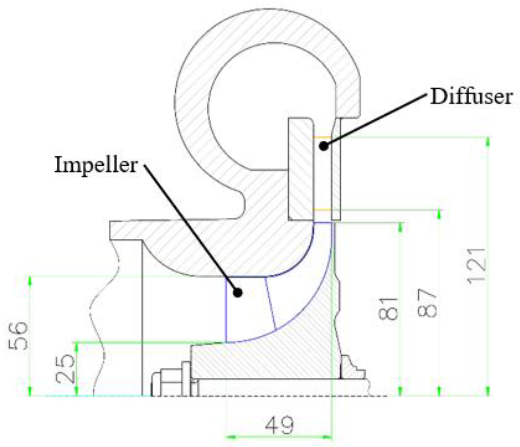
2.1. Conventional Compressor

The conventional compressor with a conventional ruled impeller and a vane radial diffuser is developed by the Institute of Engineering Thermophysics, Chinese Academy of Sciences for a small gas turbine engine to produce a pressure ratio of 5:1 at the design mass flow rate. The main design parameters are shown in Table 1. The conventional compressor is a highly loaded compressor for small jet engine applications, and the impeller inlet tip Mach number is 1.5, with a rotation speed of 65,000 rpm under the designed conditions. Therefore, the compressor is an appropriate reference for investigating the advanced impeller design method in this paper. The meridional flow path in the compressor is shown in Figure 1. It should be noted that the axial diffuser of the centrifugal compressor, which is required in real jet engines, is not discussed in this paper due to its small impact on the research conclusions.

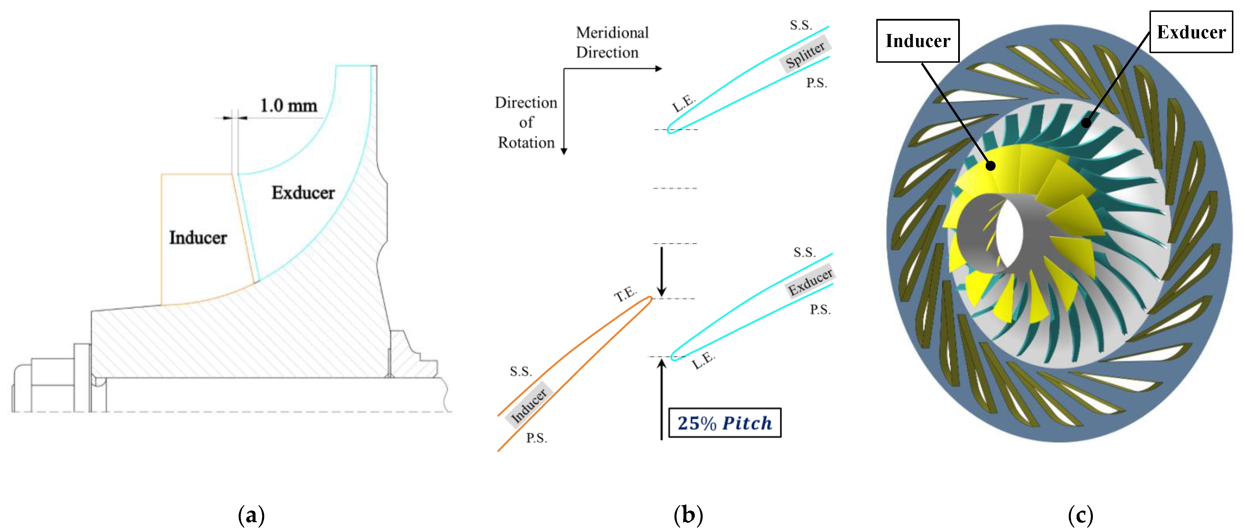
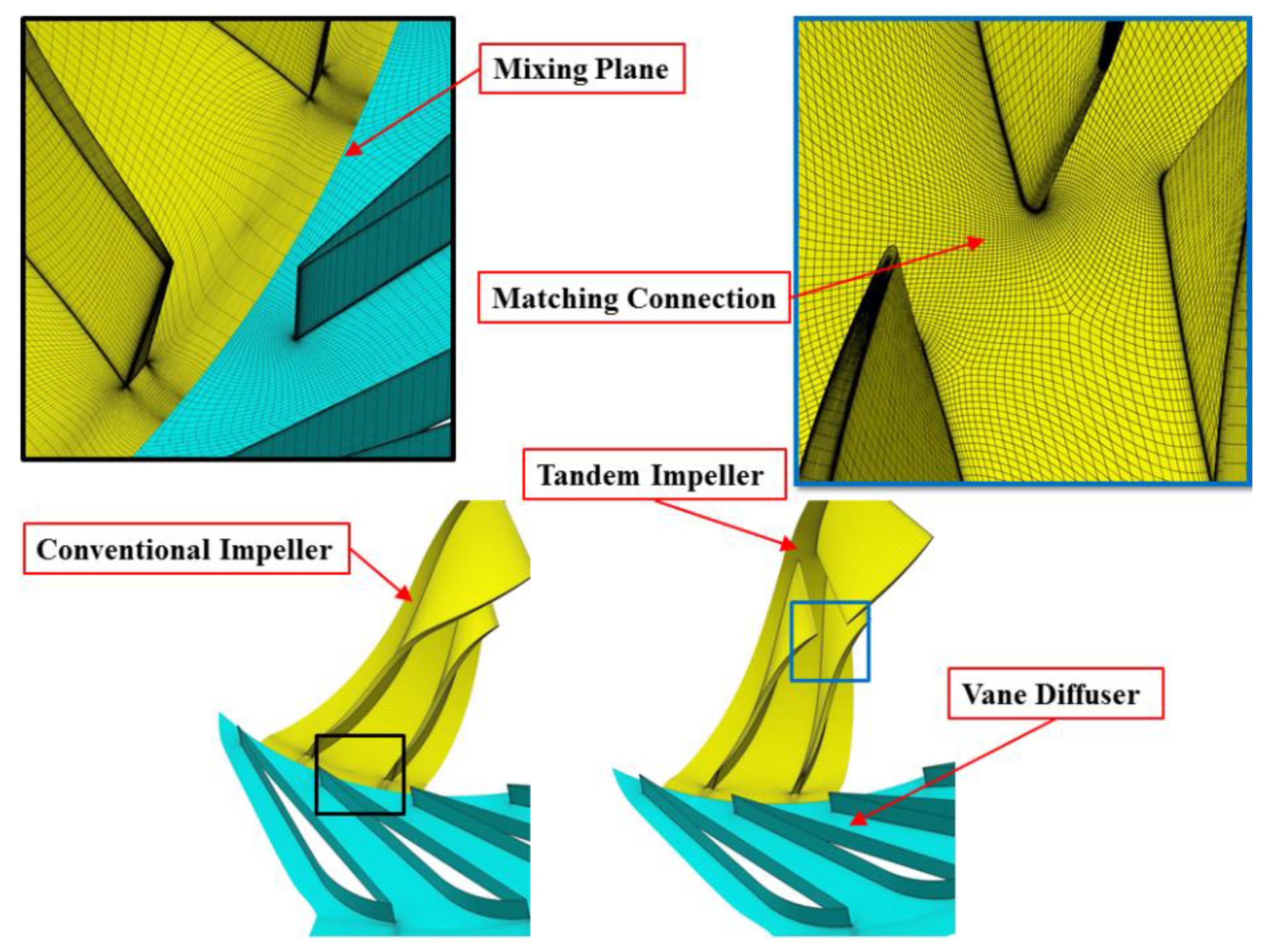
2.2. Compressor with Baseline Tandem Impeller

Based on the conventional compressor, a baseline tandem impeller is generated considering a conventional ruled impeller. The baseline tandem impeller is designed as follows. First, with the meridional flow path shape unchanged, the conventional ruled impeller is divided into two rows (inducer and exducer) at the meridional location of the leading edge of the splitter, and the axial gap between the two rows is set to 1 mm (Figure 2a). Second, based on inducer and exducer blades with ruled surfaces for the baseline tandem impeller, the blade angle distributions are identical to those in the conventional ruled impeller, and the blade thickness distributions are slightly changed to satisfy the requirement of the newly generated inducer trailing edge and exducer leading edge within the tandem impeller configuration. Finally, the circumferential displacement of the inducer pressure surface and exducer suction surface is set to 25% of the exducer blade pitch (Figure 2b), which is a satisfactory arrangement for achieving good compressor performance [14]. As a result, the baseline tandem impeller is generated, and the 3D geometry is shown in Figure 2c.

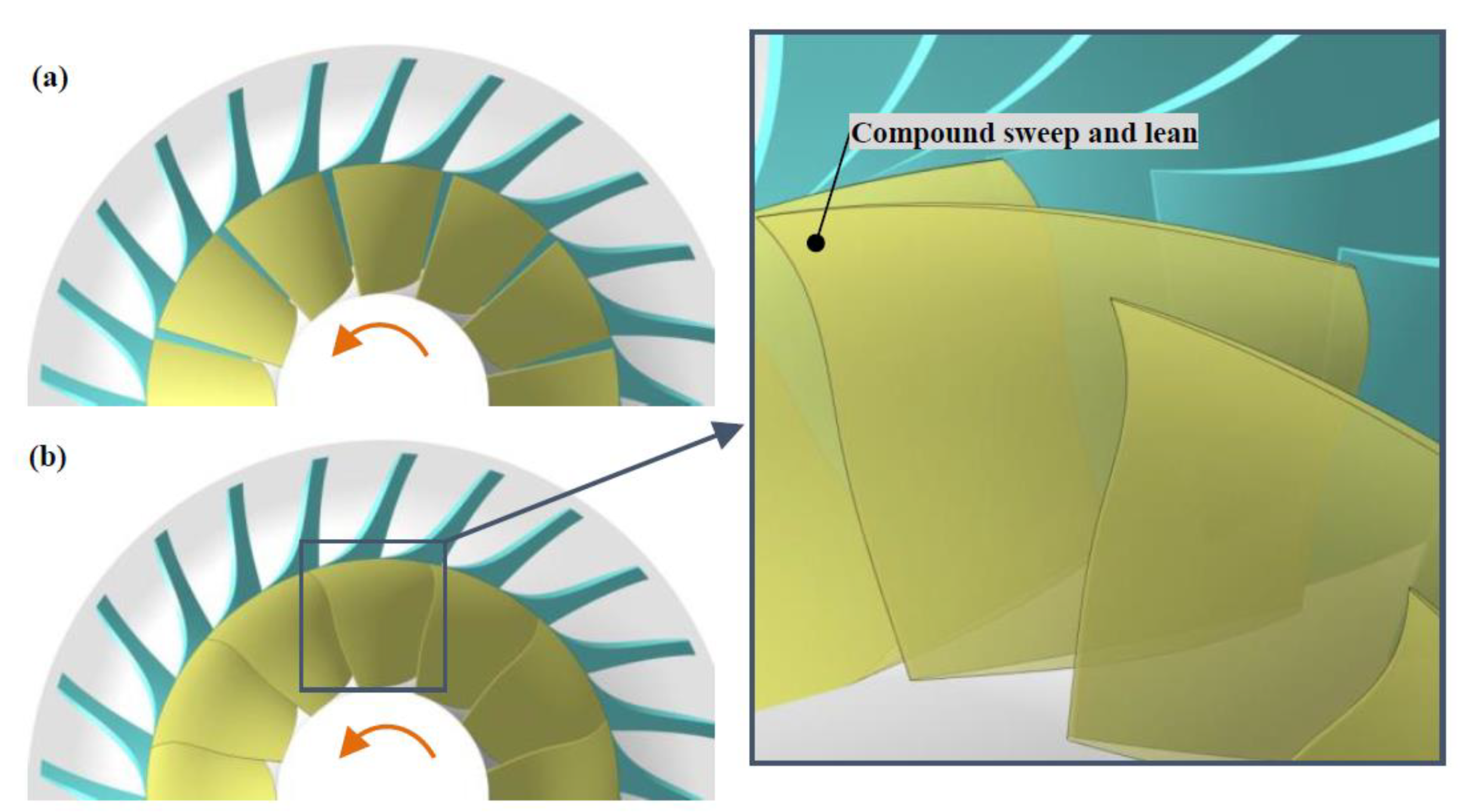
2.3. Compressor with a Free-Formed Tandem Impeller

In contrast to the ruled blade designed for the two control sections with 0% and 100% blade spans, the free-formed blade is designed by stacking the 0% and 100% span sections and many other midspan sections, thus creating a comparatively arbitrary blade geometry. In the present investigation, the free-formed tandem impeller is generated by replacing the ruled inducer blade within the baseline tandem impeller with a free-formed inducer blade. As shown in Figure 3, five control sections with 0%, 20%, 50%, 80, and 100% spans for the inducer blade are chosen to achieve a 3D free-formed inducer design, which can be fundamentally attributed to the effects of blade sweep and lean despite the complicated geometrical changes. The definitions of the blade sweep and lean within centrifugal compressors are different from those for axial flow compressors [17]. The inducer blade of the baseline tandem impeller is considered to be swept when varying the blade chord in blade tip sections and keeping the blade angle and thickness distribution the same (maintaining the blade circumferential position of the trailing edge at the hub and tip, and maintaining the blade hub chord). As shown in Figure 4, extending the blade chord length at blade tip sections is called a forward sweep, and shorting the blade chord length at blade tip sections is called an aft sweep. The inducer blade is considered to be leaned when varying the circumferential locations of midspan blade sections (Figure 5); a variation in the direction of rotation reflects a positive lean, and that in the opposite direction is a negative lean. In other words, the displacement lengths of the blade section are shifted in the same or opposite direction as rotation. As a result, the definitions above can simplify the investigation of free-formed inducer blades considering sweep and lean effects.
In this paper, six values of the sweep parameter (F = ±2 mm, ±4 mm, +6 mm and +8 mm) are considered in the parametric sweep study, where F = 0 corresponds to the leading edge at the tip of the conventional impeller, and these different values correspond to extending or shortening the blade tip section. To reduce computational costs, an inducer blade sweep study is performed in isolation to identify the sweep effects and obtain the best sweep parameter value. Next, a parametric study of blade lean is conducted using seven values of the lean parameter (L = ±1 mm, ±2 mm, +3 mm, −4 mm and −5 mm) at two blade sections of 50% and 80% spans. As a result, a modified tandem impeller with an appropriate 3D inducer design can be achieved. It is necessary to note that the main purpose of this paper is to explore the potential and underlying flow mechanisms of the 3D inducer design, and no attempt is made to maximize compressor performance by optimizing the sweep and lean parameters.

3. Numerical Method and Validation

3.1. Numerical Method

The Euranus solver in Numeca Fine/turbo software has been extensively used for axial and centrifugal turbomachines and has been validated in many studies. In this paper, steady simulations were conducted using Euranus to investigate the performance and flow structures of different centrifugal compressors by solving the RANS (Reynolds-averaged Navier-Stokes) equations. The S-A one equation turbulence model was used to close the equations. The discretization is based on a finite volume approach. The Jameson second order scheme with scalar artificial dissipation is used for the convective terms while the diffusive terms are discretized using second order central schemes. Temporal integration is based on the dual-time step method. At each time step, a steady problem is thus solved using an explicit forth order Runge-Kutta scheme accelerated with the use of multi-gridding, local time-stepping and residual smoothing.

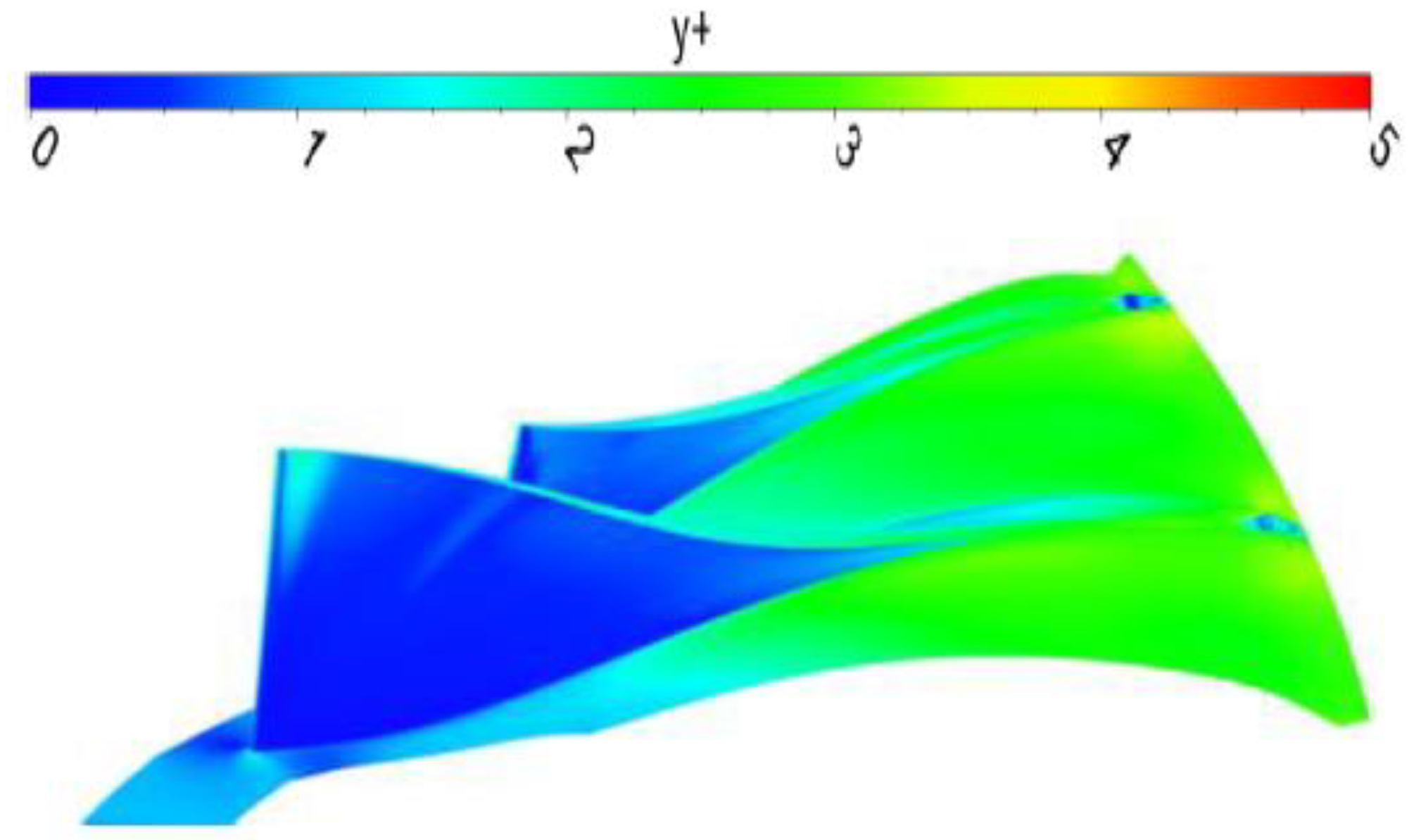
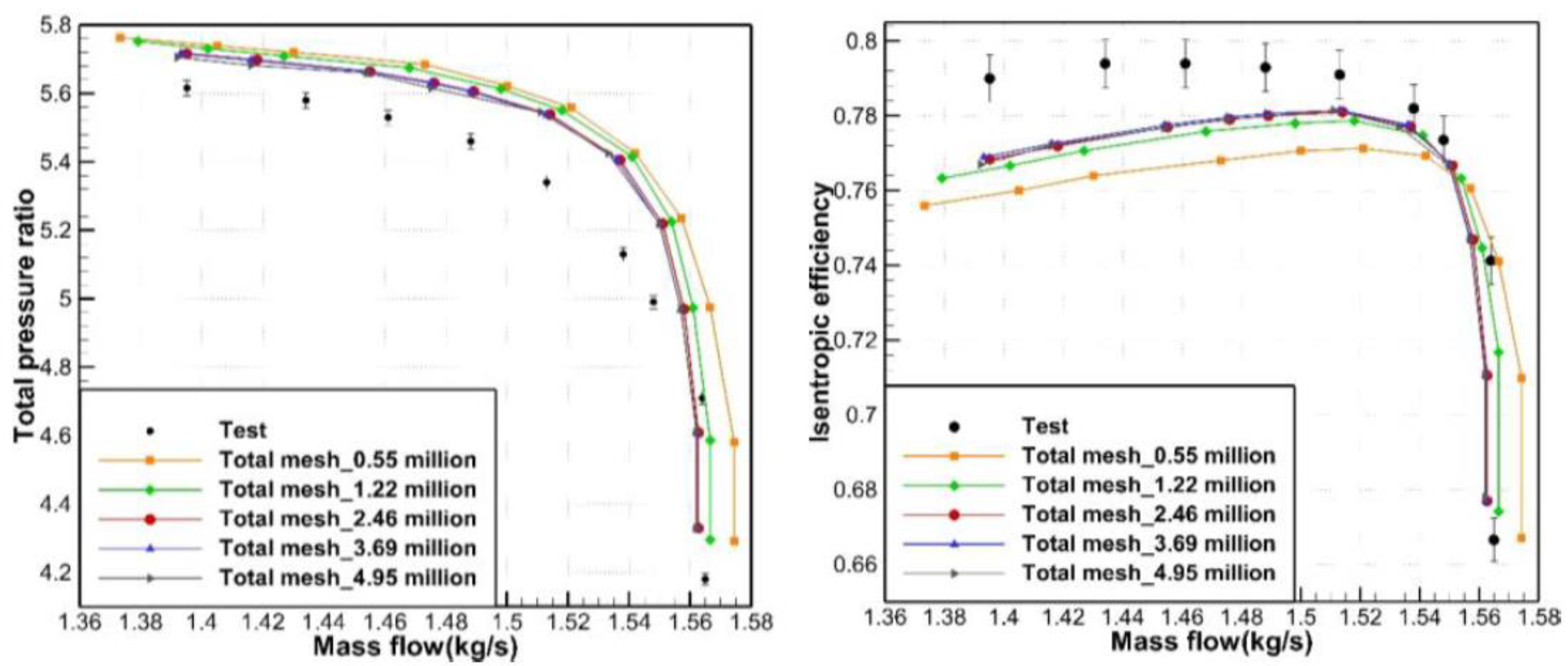
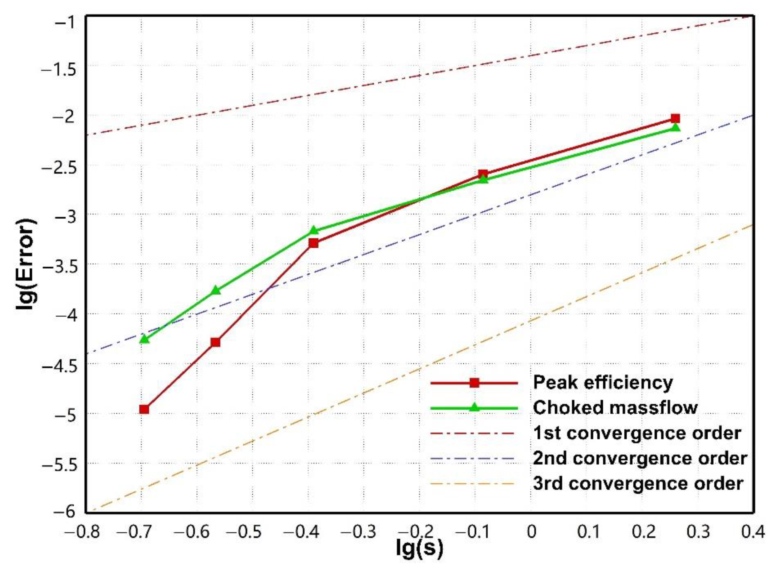
3.2. Calculation Mesh and Experimental Validation

Figure 6 shows the mesh topologies of the investigated compressors with conventional and baseline tandem impellers. The compressor computational domain is only a single passage considering the periodicity hypothesis, and the blocks of the impeller blade passage, tip clearance region and wedge diffuser passage are independently generated to predict the coupled flow. The inducer blade and exducer blade of the tandem impeller are also independently meshed with matching connections. The spacing of the first elements near the wall is maintained at 0.002 mm to achieve a dimensionless distance y+ of no greater than 5 (Figure 7). For comparability, the mesh topologies and node distributions of the compressors with conventional impeller and tandem impeller are almost the same, except those for the regions near the newly generated inducer trailing edge and exducer leading edge of the tandem impeller. In addition, the mesh of the free-formed tandem impeller is identical to that of the baseline tandem impeller.
The boundary condition details are shown in Table 2. All the compressor calculations start from the choke condition and stop at the stall condition with increased static back pressure. Since the main concern of this study is the compressor efficiency variations among different impeller designs, no attempt has been made to accurately determine the stall limit.
The mesh independence and numerical accuracy are evaluated based on the calculations and experimental results for the conventional compressor. Figure 8 shows comparative plots of compressor-stage performance at 100% rotation speed resulting from different mesh sizes of 0.5–5 million nodes. For the coarsest mesh grid of 0.5 million nodes, a brief description on the impeller blade passage, tip clearance region and wedge diffuser passage node distribution are shown in Table 3. On this basis, the meshes were generated by multiplying the coarsest grid dimensions by suitable factors (Table 4). The experimental compressor performance map and relative error bar are included in Figure 8. Notably, the peak total pressure ratio, peak efficiency and choked mass flow are almost the same as the mesh size approaches 2.5 million.
Furthermore, based on the equivalent grid size S (inverse of the grid number), the discretization error of the peak efficiency EP.E. and the choked mass flow Echoke summarized in Table 3, a log-log plot of the three parameters was drawn, as shown in Figure 9. Roache [18] demonstrated that mesh convergence behavior can be quantitatively investigated by evaluating the error convergence order, namely, the slope of the resulting line, where a minimum order of 3 can be achieved as the grid size increases to approximately 2.5 million cells. Therefore, the mesh size is chosen as ~2.5 million considering both the mesh independence requirements and computational costs. The calculation results for a mesh size of ~2.5 million agree well in magnitude and trend with the experimental results, thus validating the accuracy and reliability of the numerical method used in this study.

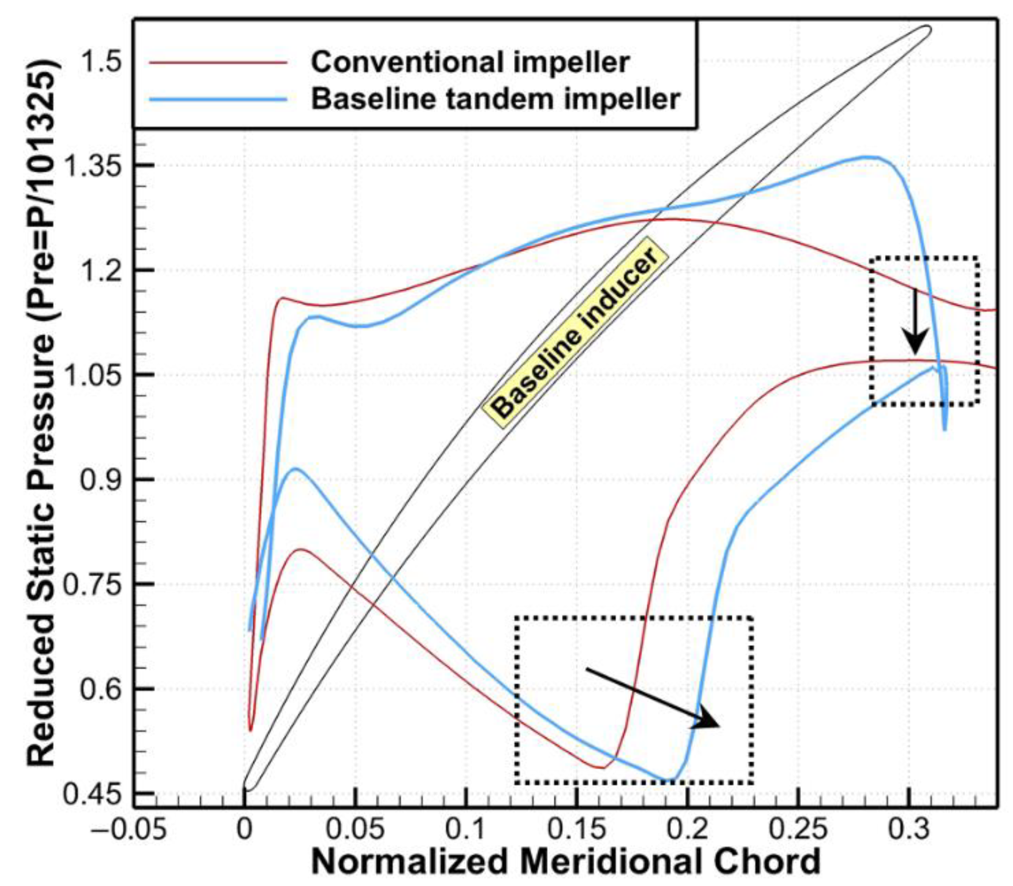
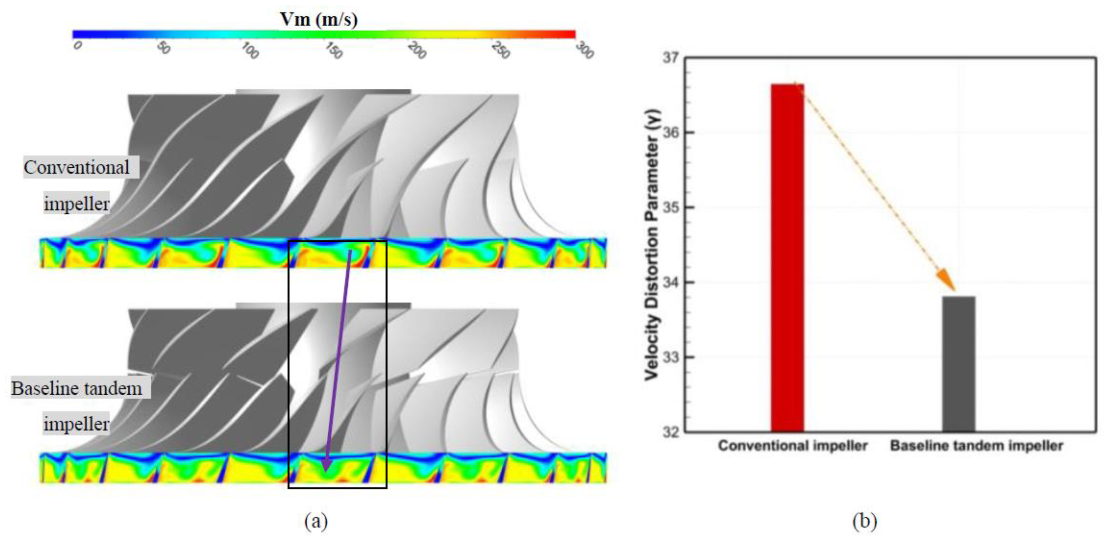
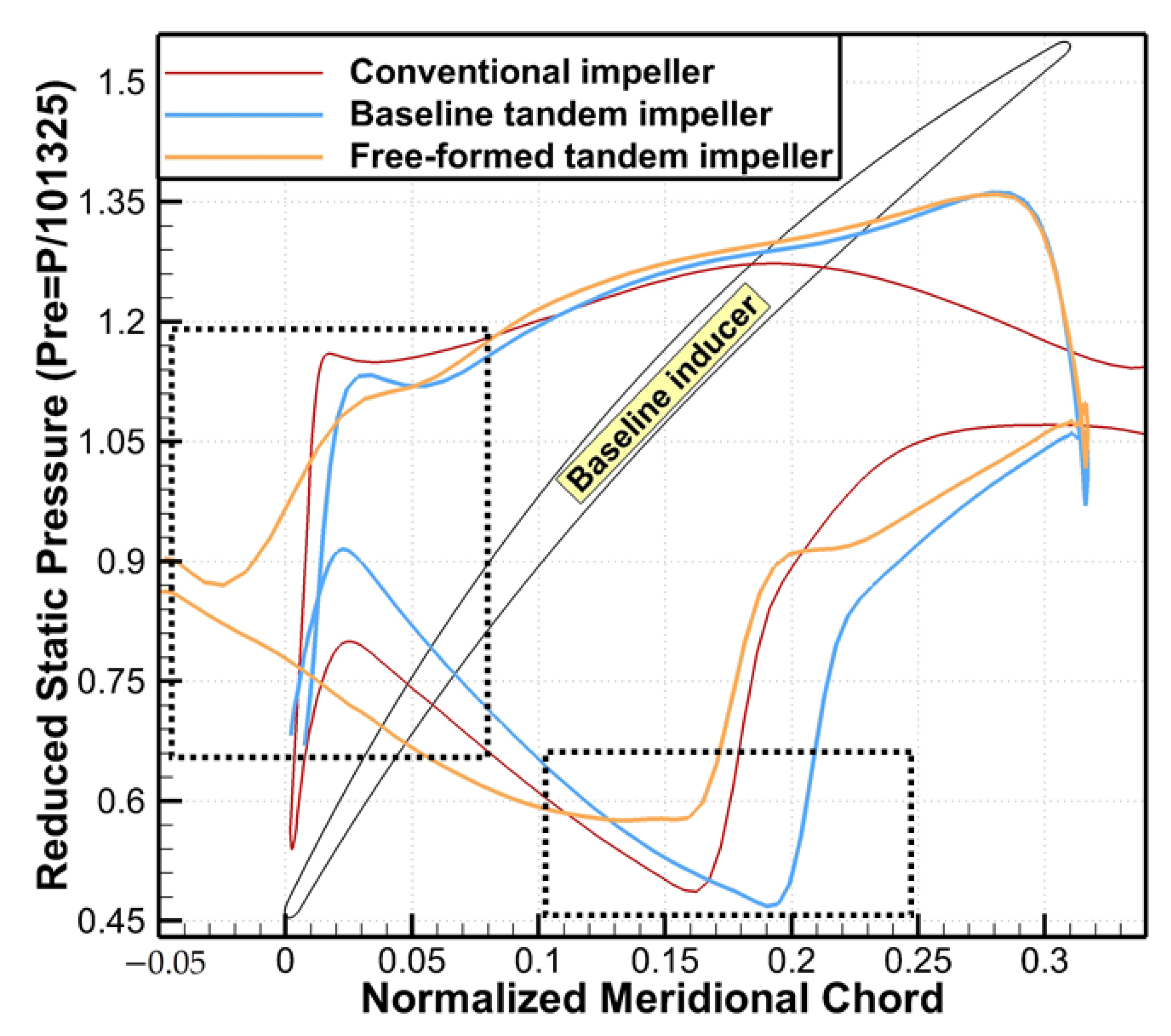
4. The Effect of the Baseline Tandem Design on Compressor Performance and the Corresponding Mechanism

As the first step, the conventional impeller in the compressor stage is replaced by the baseline tandem impeller. Figure 10 shows the performance of the baseline tandem-designed compressor, which is compared with that of the conventional compressor, and a significant efficiency gain of 1.4% is achieved with no pressure ratio penalty.
The compressor-stage efficiency gain is resulted from the performance variations in both the impeller and diffuser components. In order to identify the underlying influence of the tandem design on the compressor performance change, the stage peak efficiency points (P.E. points) in the two cases are selected for comparison. Figure 10 presents the impeller and diffuser efficiency variations with and without employing the baseline tandem impeller, and the diffuser efficiency is assessed based on the total pressure loss coefficient Cpt. Both the impeller and diffuser efficiencies are improved in the tandem-designed compressor, and the diffuser flow loss reduction contributes to the majority of the efficiency gain (approximately 70%) in this stage compared with the contribution of the impeller efficiency gain (approximately 30%). For the impeller component, Figure 11 presents the entropy distribution at the meridional plane of the two impellers at a P.E. point, and the difference is mainly illustrated in the tip region of the inducer part. Figure 12 compares the flow structure at a 95% blade span for the two impellers, and the inducer passage shock for the baseline tandem impeller moves significantly downstream. Furthermore, the inducer loading distributions at a 95% blade span are shown in Figure 13, which further verifies the downstream shift of the passage shock within the tandem impeller.
The underlying mechanism of the shock pattern variation can be contributed to the interaction between the inducer and exducer blades (potential effect). As we know, the tandem impeller configuration implies an independent inducer blade, and the local pressure near inducer blade trailing edge will be changed due to the inducer/exducer interaction. In other words, the back pressure of the inducer blade will be locally changed by the potential effect of the exducer blade, which further affect the shock pattern within the inducer blade passage. In the present study, the back pressure of the inducer blade within the tandem impeller is considerably reduced compared with the corresponding pressure at the conventional impeller suction surface. The potential effect within the tandem impeller significantly reduces the inducer blade back pressure. As a result, the inducer passage shock shifts downstream, and the flow loss induced by the shock/boundary layer interaction is reduced when applying the tandem impeller design.
For the performance gain contributed by the diffuser, particular emphasis should be placed on the effect of the tandem impeller design on the impeller discharge flow quality, which directly affects diffuser performance. Figure 14 shows a comparison of the discharge flow pattern and the flow uniformity denoted by the velocity distortion parameter γ  ( γ = ( V m V m ¯ ) 2 d A / V m d A ) for the two impellers. The conventional impeller outlet exhibits a typical “jet-wake” flow pattern, where the relatively low-momentum flow region (wake) is located at the impeller suction surface/shroud corner and the high-momentum flow region (jet) is located at the impeller pressure surface/hub corner. However, the “jet-wake” flow pattern is significantly diminished for the baseline tandem impeller; additionally, the location of the wake region moves to the pressure side, and the low-momentum flow is largely diminished. As a result, the flow uniformity in the baseline tandem impeller is significantly improved (Figure 14b), which is similar to the results in reference [5,12,19,20] concerning the tandem impeller configuration.
In order to identify the underlying flow mechanisms related to the effect of the tandem design on discharge flow uniformity, it is important to focus on the flow structure variations within the impeller passages. As shown in Figure 15, six impeller passage sections at different meridional locations are chosen to compare the flow patterns of the two impellers. Figure 16 and Figure 17 compare the flow patterns at sections (I-VI) based on the contours of the meridional velocity Vm and relative helicity H, where H is defined as the shedding of the streamwise vortex to illustrate the secondary flow and the positive helicity indicates a clockwise vortex [21]. Compared with the intense secondary flow directed from the impeller pressure surface to the suction surface within the conventional impeller, which results in a highly distorted discharge flow, the secondary flow contributed by the Coriolis force (vortex CV) within the tandem impeller is significantly suppressed by the newly generated inducer shedding vortices: the PSV (pressure surface shedding vortex) and SSV (suction surface shedding vortex). In addition, the PSV and SSV enhance the interactions between low-momentum and high-momentum flows, which further improve the discharge flow uniformity. As a result, the tandem design can rearrange the secondary flow pattern in the impeller and reduce low-momentum flow generation and accumulation at the impeller outlet, thus greatly enhancing the downstream diffuser performance and contributing to the compressor-stage performance gain.

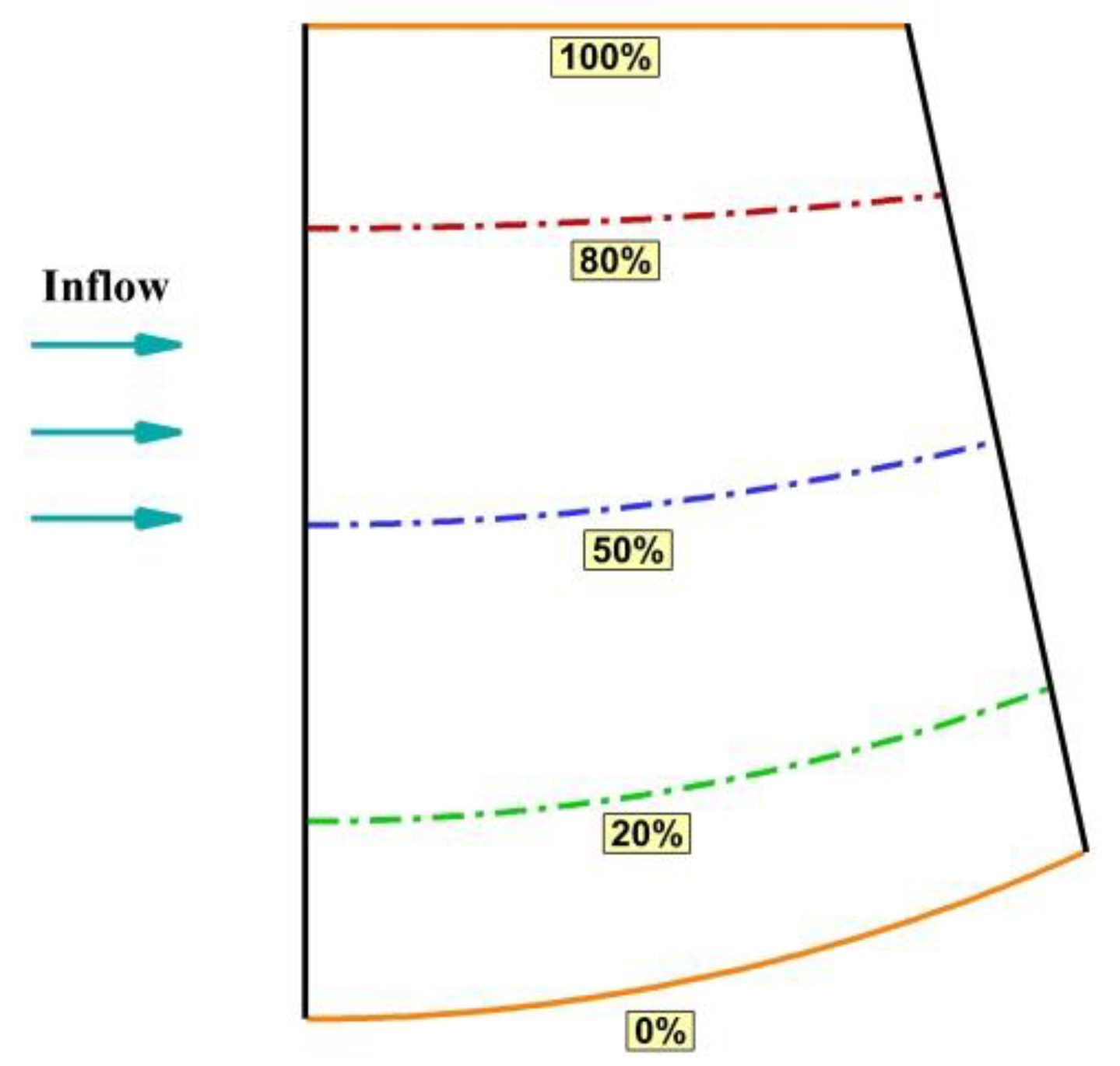
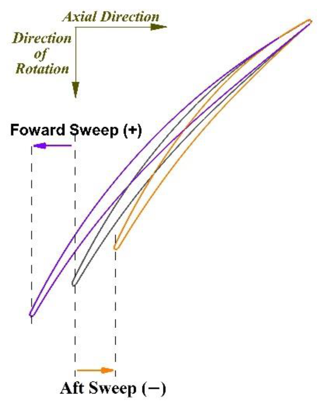
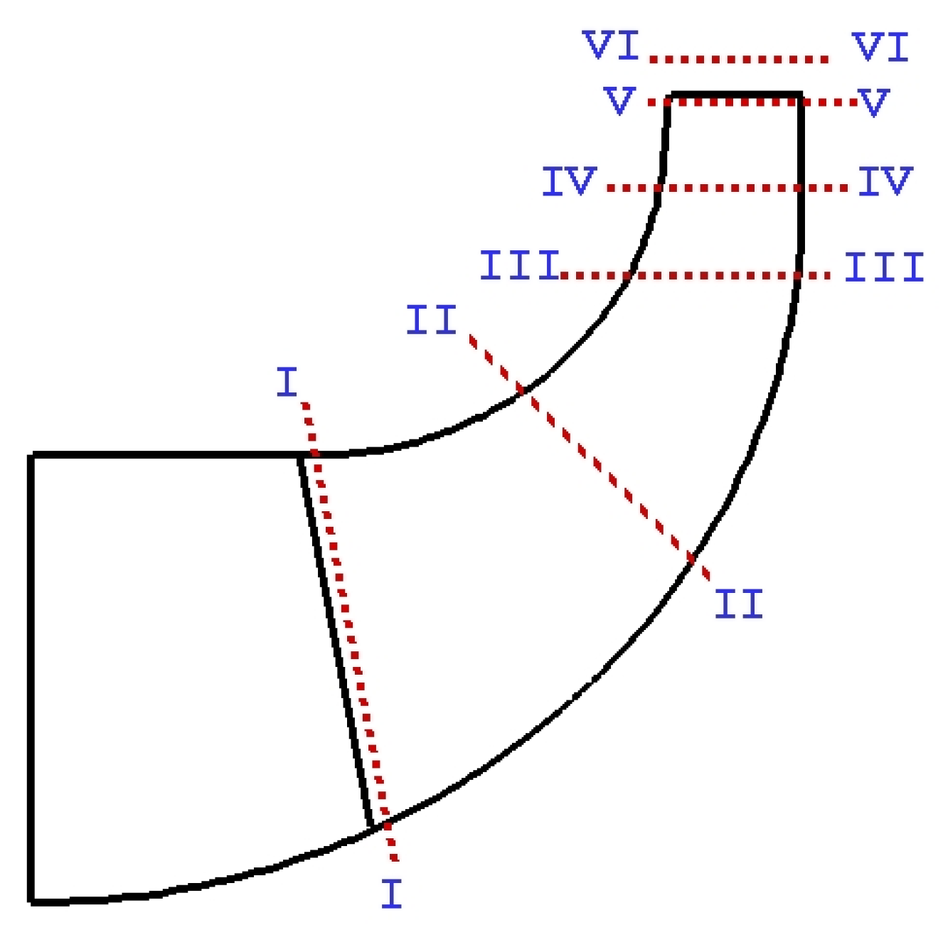
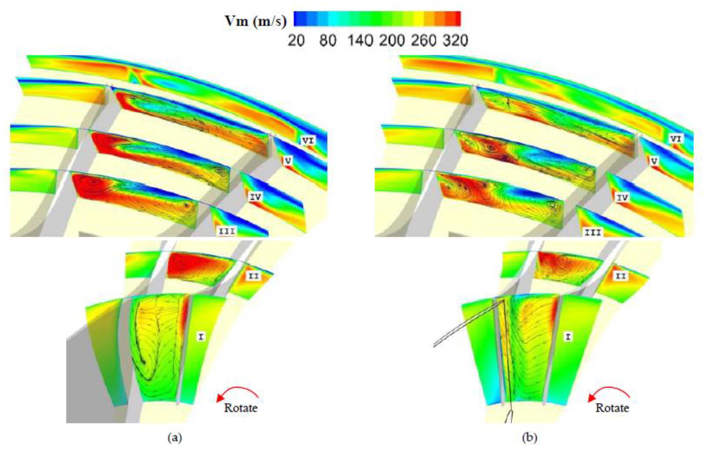
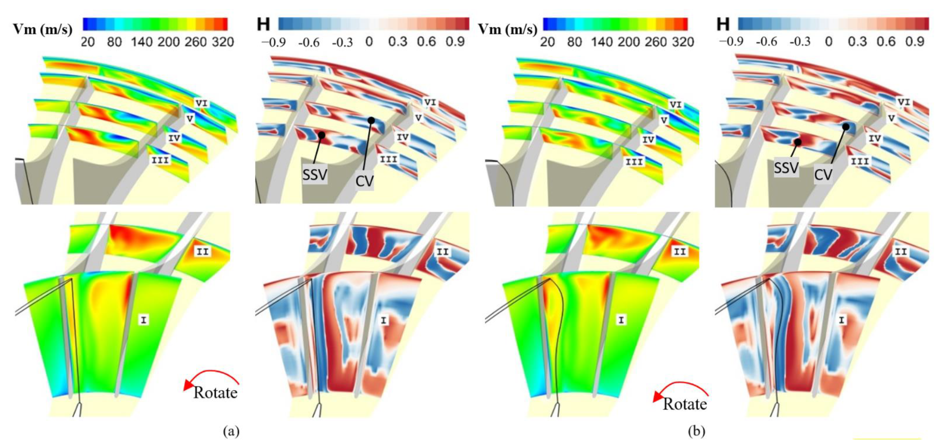
5. The Effect of the Free-Formed Inducer Design on the Compressor Performance and the Corresponding Mechanism

Based on the baseline tandem impeller, the 3D design concepts of blade sweep and lean are employed in the inducer design to further improve compressor performance. Figure 18 shows the parametric study results for the inducer sweep design. Due to article length limitations, only the performance variations at the P.E. points (versus the performance of the conventional compressor) of the proposed compressor with different impeller designs are presented. The results demonstrate that the forward sweep of F = 4 mm is a preferred inducer sweep design, which achieves a maximum compressor-stage efficiency gain of 1.76%.
Furthermore, a parametric study of inducer lean within the tandem impeller was conducted based on the inducer sweep results, and the inducer sweep was set as a constant at F = 4 mm. The results of the inducer lean study are presented in Figure 19, and the negative lean of L = −3 mm at an 80% blade span yielded the best potential for further improving compressor performance. Therefore, a tandem impeller with the free-formed inducer design was achieved by applying a forward sweep and negative lean (F = 4 mm and L = −3 mm), which yielded an efficiency gain of 2.11% (Figure 20). The 3D geometry of the free-formed tandem impeller is shown in Figure 21. Notably, the leading edge of the inducer within the free-formed tandem impeller displays compound sweep and lean characteristics that are very similar to those for an advanced axial compressor blade (i.e., the fan blade used in modern GE aircraft engines [22]).
The tandem impeller configuration coupled with the free-formed inducer displayed the potential to significantly improve the performance of the highly loaded centrifugal compressor. However, the effects of the underlying physics of the 3D inducer design concepts applied for the tandem impeller on compressor-stage performance must still be assessed. Based on the results of different tandem impeller designs, the variations in the contribution to the efficiency gain at the P.E. point are compared in Figure 22. The effect of the forward sweep design only is reflected in the impeller flow loss reduction, and the diffuser flow loss is almost the same. When a negative lean design is used, the impeller flow loss remains the same, and the diffuser flow loss is reduced. Therefore, it can be concluded that the sweep design benefits from the improved quality of the flow within the impeller passages, such as shock and flow separation, and the lean design benefits from the improved impeller discharge flow quality.
In order to identify the effect and flow mechanism of the sweep design, Figure 23 compares the entropy plots at the meridional plane of the baseline tandem impeller and forward-swept tandem impeller; the main difference is in the inducer tip region. Figure 24 presents the relative Mach number contours at the blade-to-blade plane for a 95% span for two tandem impellers. The inducer passage shock intensity is significantly reduced and the relative location is shifted downstream by the forward sweep design; this result is identical to the general conclusion of a sweep study involving transonic axial compressors [23,24]. Furthermore, Figure 25 shows the inducer blade loading trend at a 95% span. With increasing blade length, tip loading near the leading edge of the forward-swept inducer blade is significantly reduced, which slows the flow acceleration near the blade suction surface and weakens the shock intensity. As a result, the impeller flow loss is reduced, and the compressor efficiency is correspondingly improved.
To assess the effect of the inducer blade lean on the results, the analysis was concentrated on the variations in the secondary flow structure and its effect on the discharge flow pattern. Figure 26 compares the evolution of the flow patterns within the passages of the baseline and free-formed tandem impellers in detail. The inducer shedding vortex SSV is circumferentially adjacent to the splitter pressure surface due to the negative lean design at an 80% blade span, and the interactions between the SSV and CV are enhanced. As a result, both the generation and accumulation of the low-momentum wake are further restrained, and the impeller discharge flow is generally uniform. The inducer lean design within the tandem impeller can further improve the secondary flow pattern within the impeller and the discharge flow uniformity, thus contributing to improved downstream diffuser performance.
Based on the discussion above, a performance improvement method for a highly loaded transonic centrifugal compressor is developed by employing a tandem impeller configuration and 3D free-formed inducer design; this approach combines the advantages of the two innovative concepts and achieves a 2.11% compressor-stage efficiency gain with no pressure ratio penalty. In addition, the design method achieves a balance between the compressor manufacturing cost and performance. All these results demonstrate the superiority of the design method investigated in this paper over conventional methods.

6. Conclusions

The flow within the highly loaded transonic centrifugal compressors is very complex due to the presence of shock waves and deteriorated flow uniformity, which decrease the impeller and diffuser performance, respectively. For these compressors, the organization and control of the transonic and secondary flows within the impellers are of vital importance. This paper conducts a detailed investigation of a highly loaded transonic centrifugal compressor designed with a tandem impeller configuration and a 3D free-formed inducer; notably, the shock is weakened, and flow uniformity is significantly improved, which proved the effectiveness of using tandem impeller configuration and 3D free-formed blade design concepts to improve the transonic compressor performance. As a result, the energy consumption of the corresponding industrial products can be directedly decreased. The main conclusions drawn from this study are as follows:
(1)
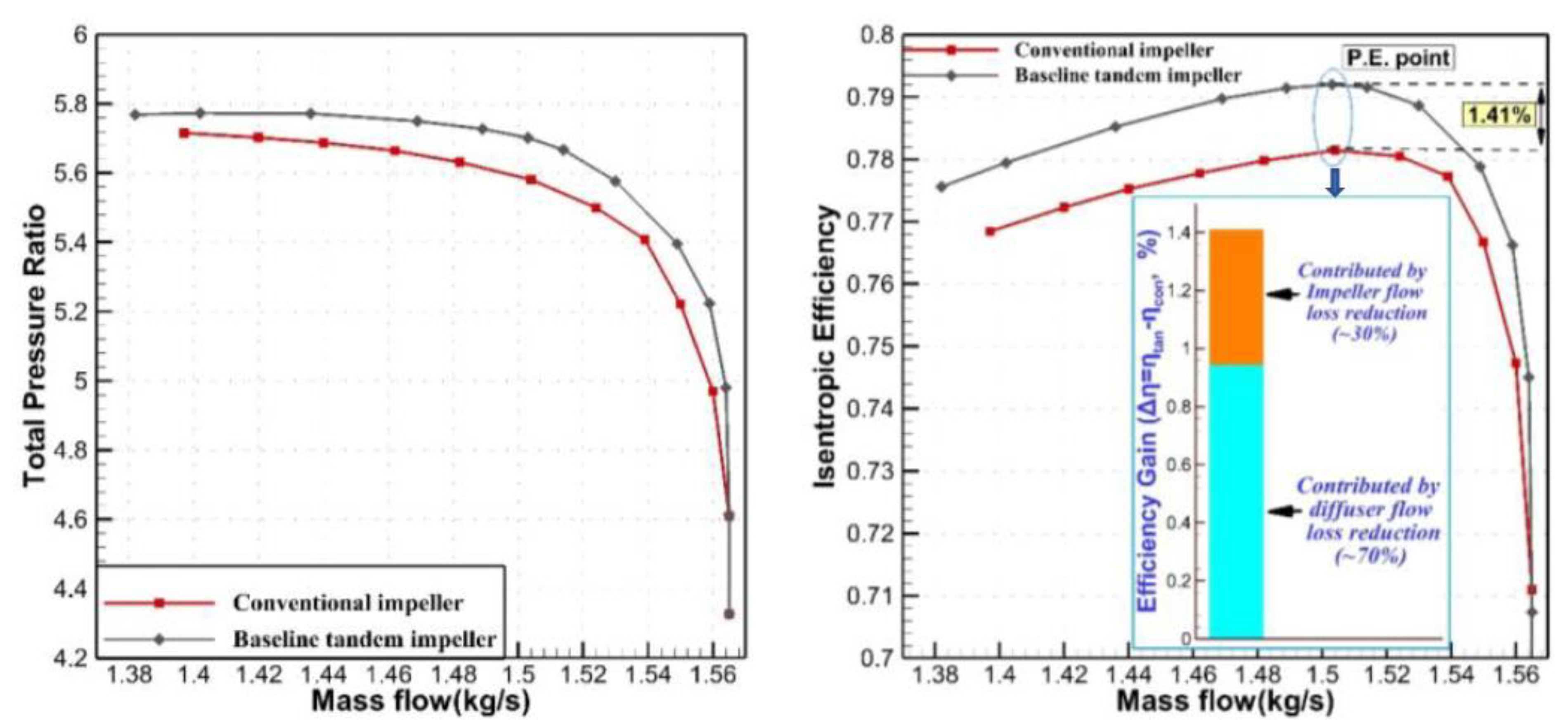
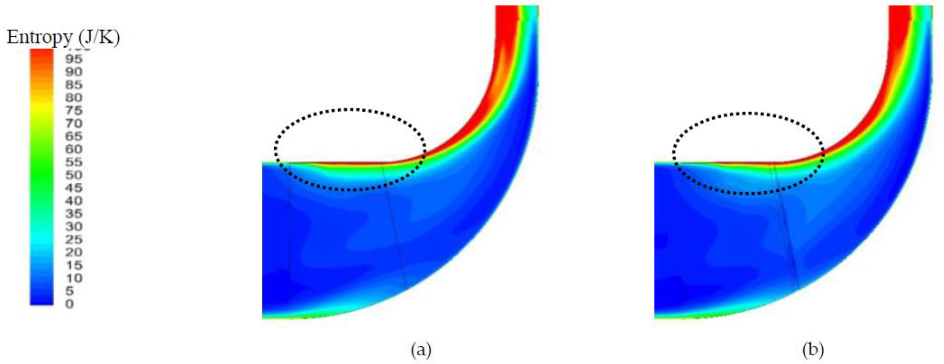
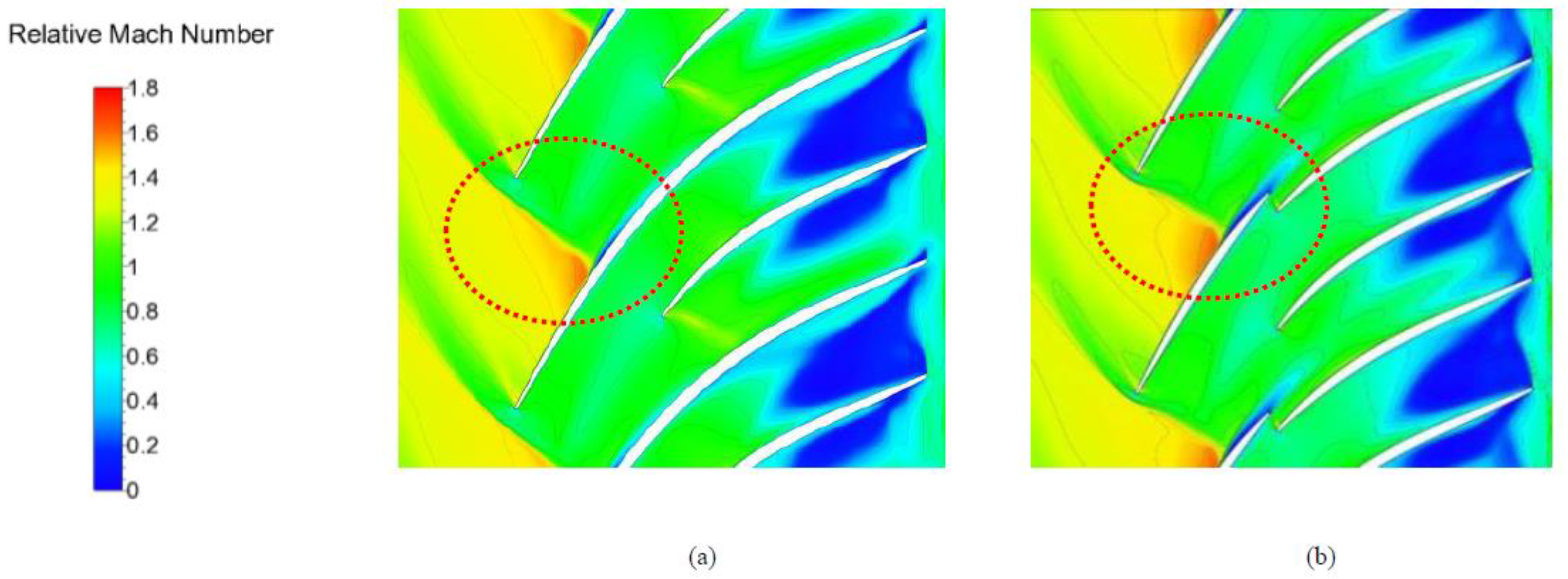
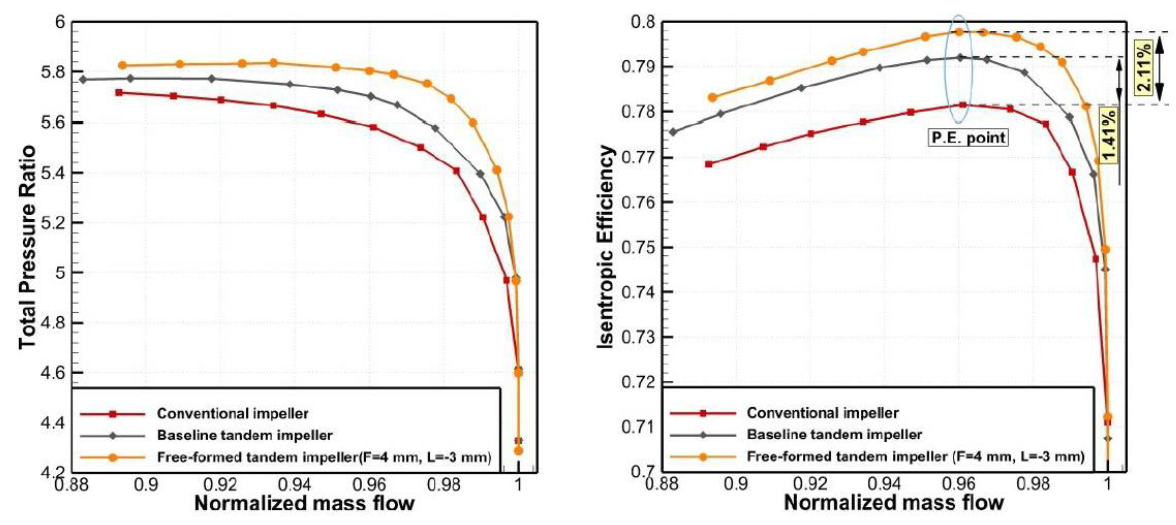
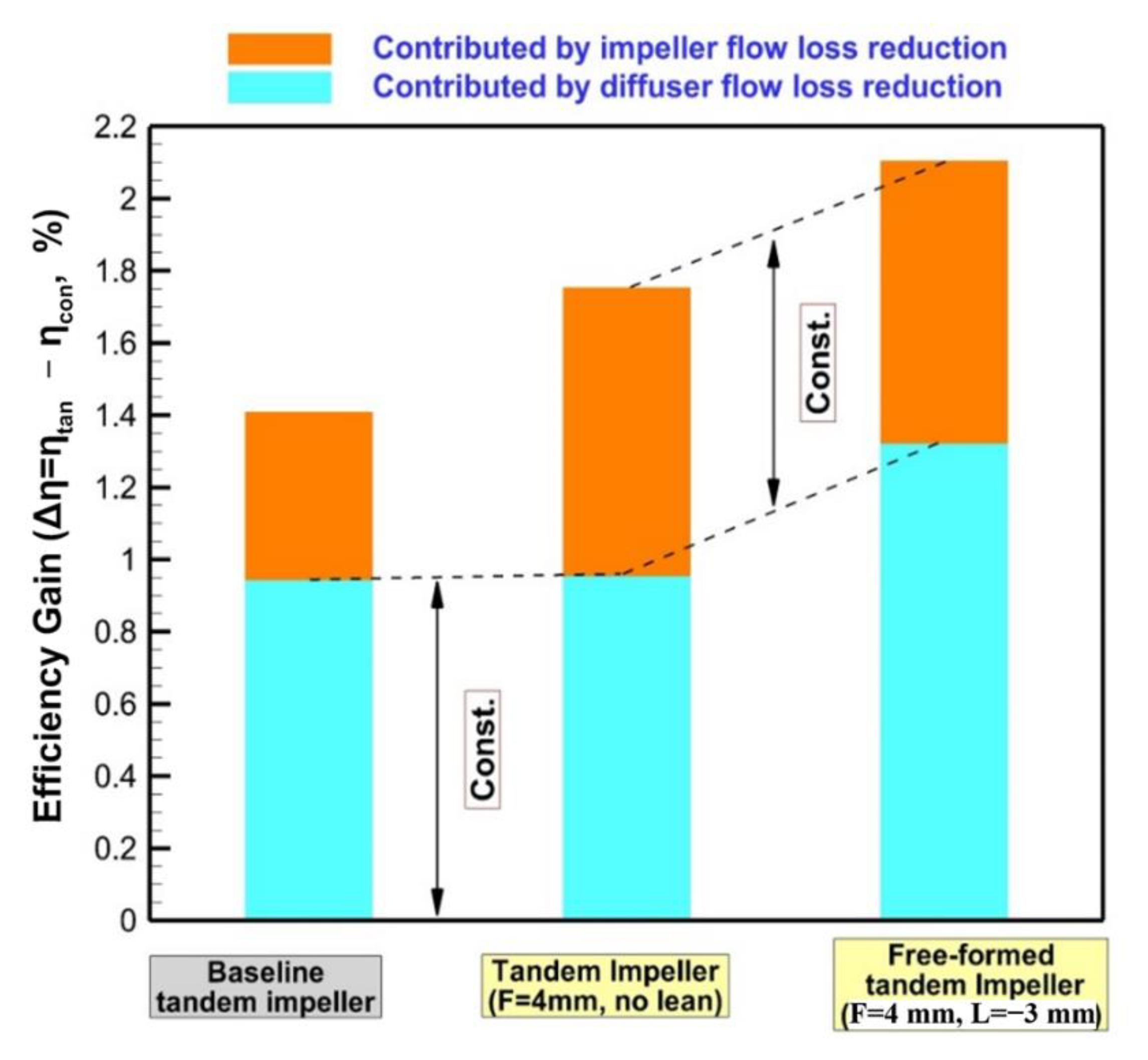
The compressor performance is significantly improved by the tandem impeller configuration with the rule-surfaced inducer and exducer blades. A compressor efficiency gain of 1.4% is achieved through both impeller and diffuser flow loss reductions. Due to the potential effects within the tandem impeller, the low-pressure region at the leading edge of the exducer blade suction surface reduces the blade back pressure at the inducer, the passage shock moves downstream, and impeller flow loss is reduced. Due to the positive and negative inducer shedding vortices induced by the tandem design, the generation and accumulation of the low-momentum flow (wake region at the impeller outlet/diffuser inlet) are partly restrained, and the flow loss at the downstream diffuser is reduced.
(2)
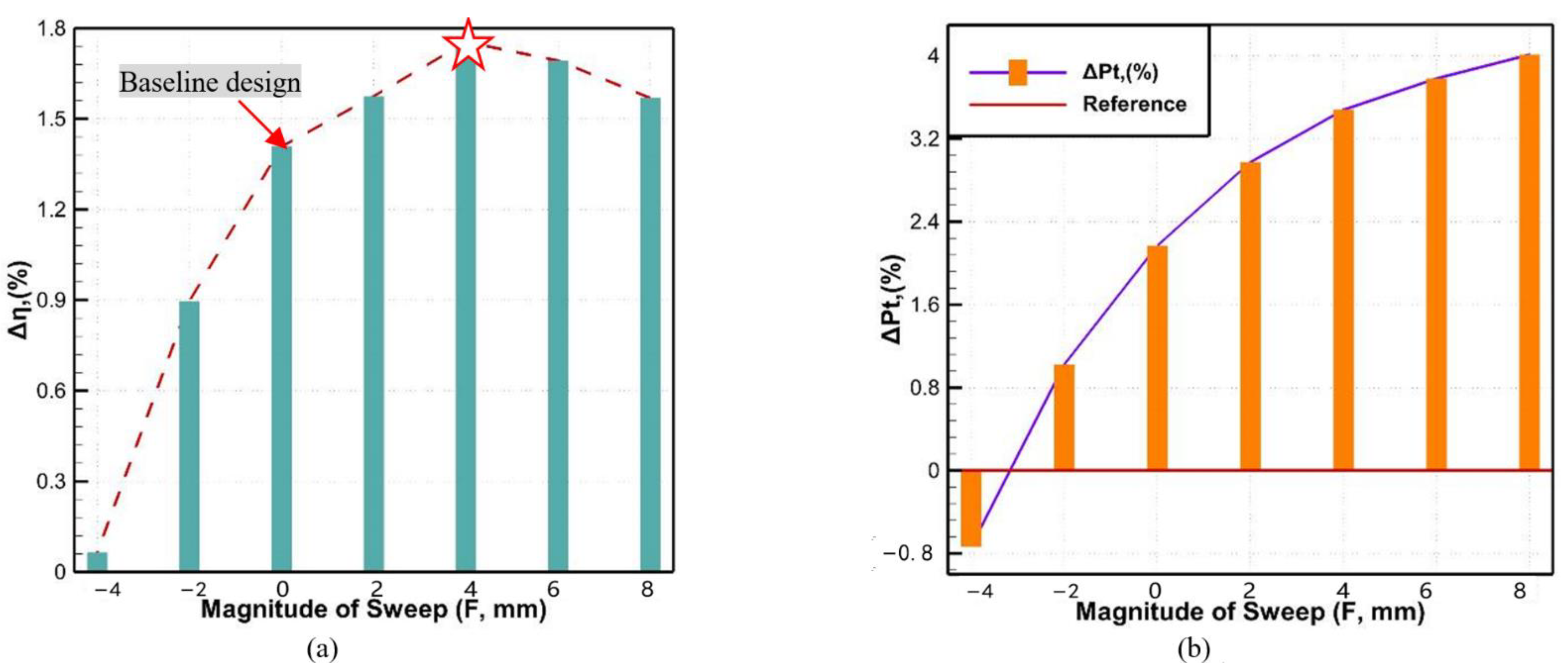
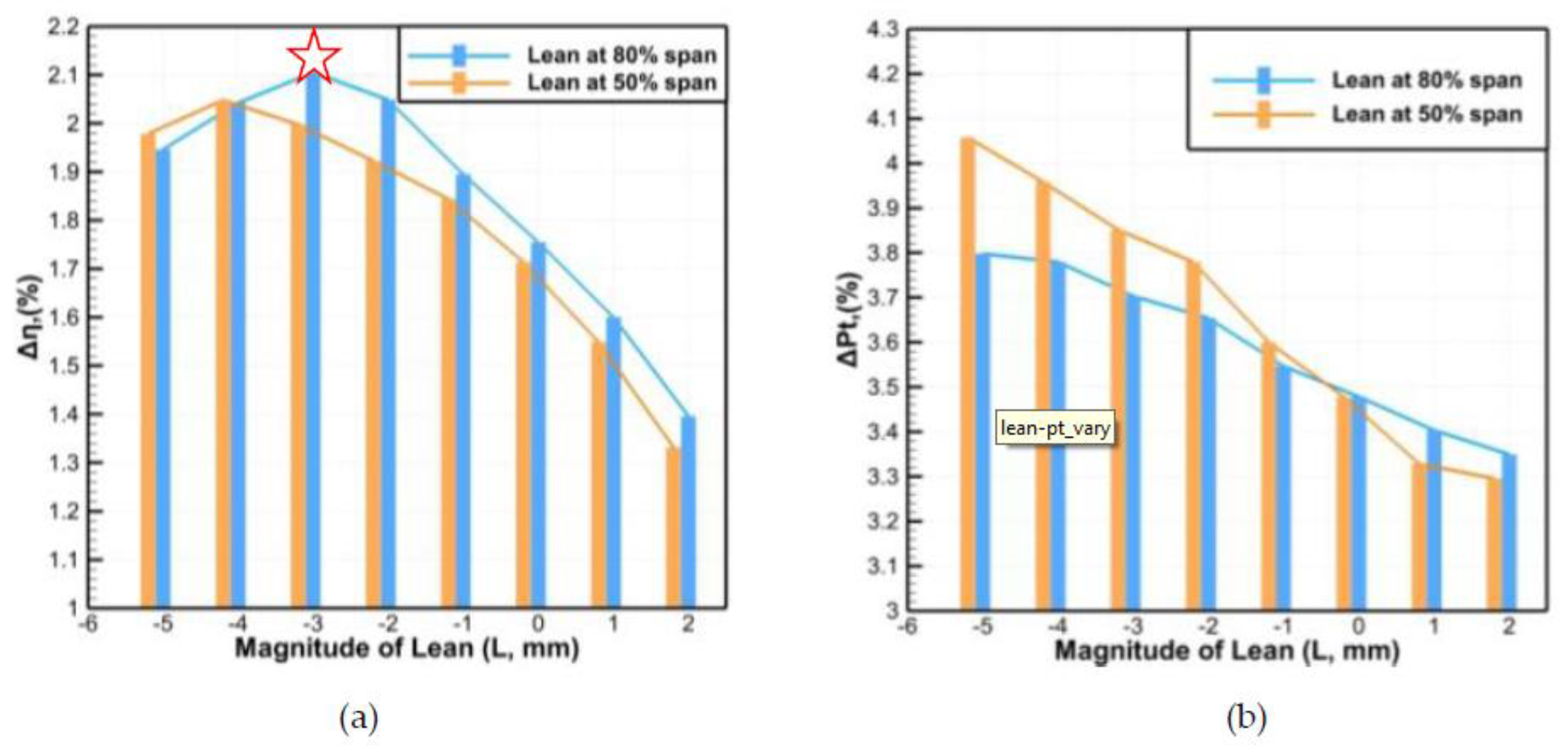
The tandem impeller configuration involved the successful application of 3D design concepts for centrifugal impellers. This approach can reduce the manufacturing and cost limits by applying a divided inducer blade. Based on the tandem impeller configuration, employing a forward sweep and negative lean design for the impeller can further improve compressor performance; notably, the efficiency gain compared with that for a conventional compressor reaches up to 2.11%. The 3D free-formed inducer within the tandem impeller exhibits a very similar leading-edge geometry as that for an advanced axial transonic blade.
(3)
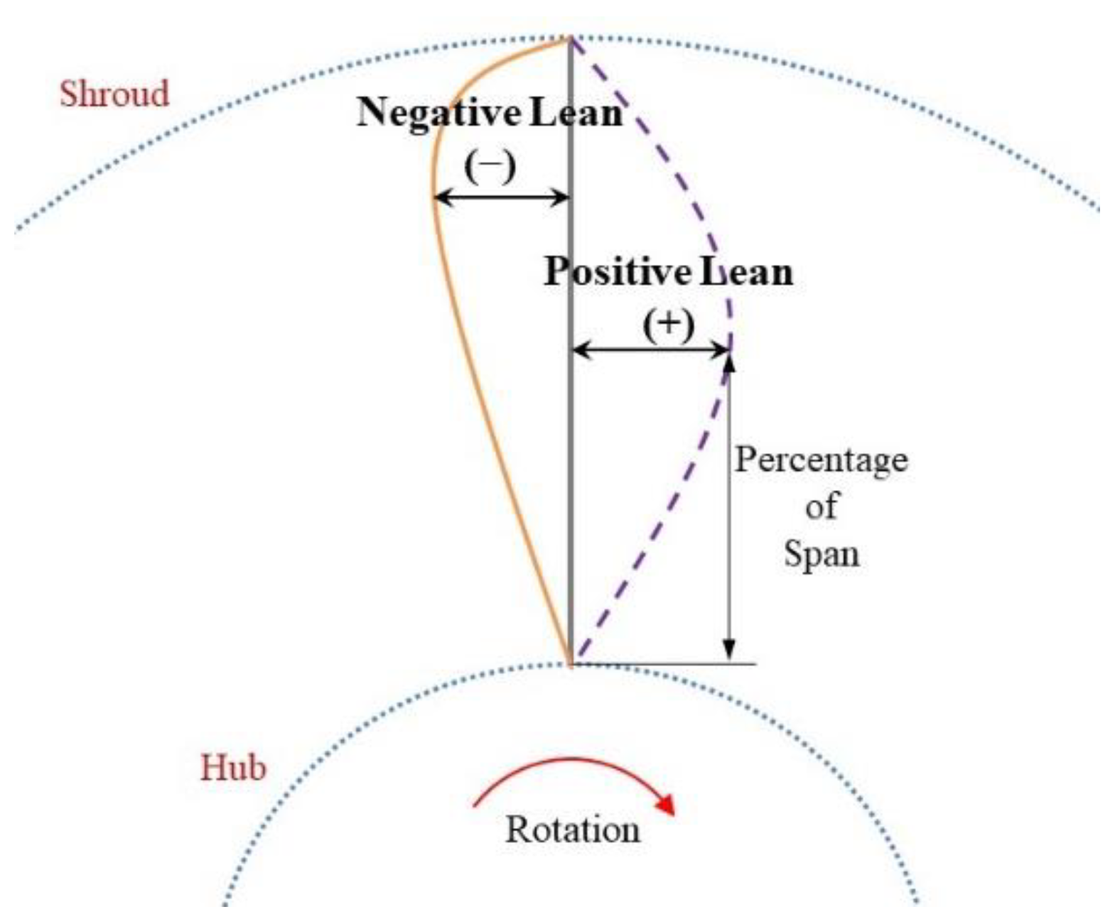
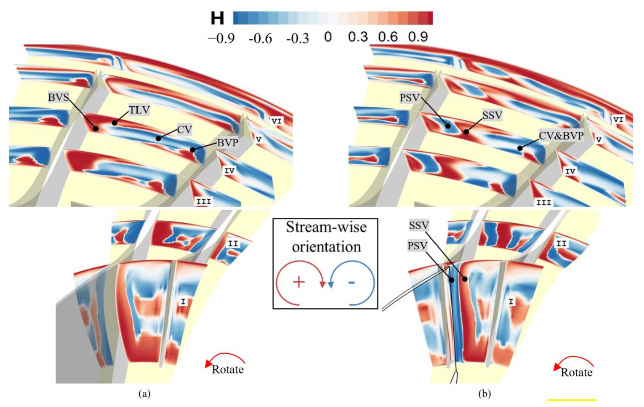
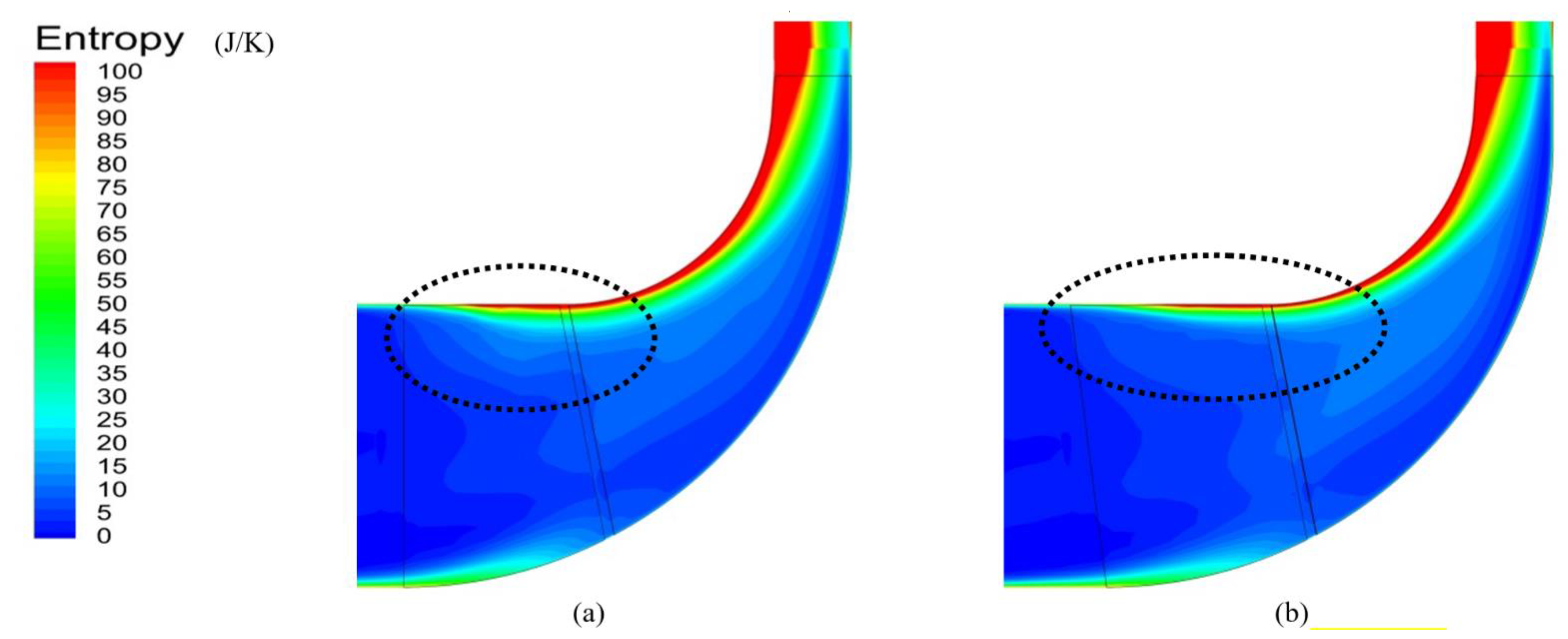
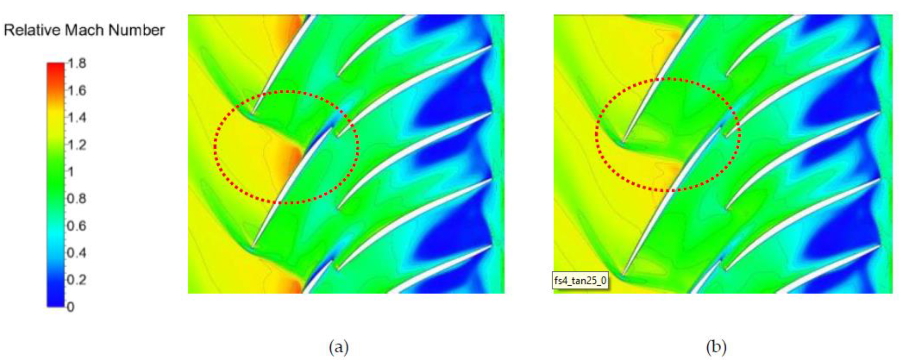
With the extended inducer blade chord at the tip, the inducer forward sweep design can reduce the flow acceleration before the passage shock, thus further decreasing the impeller flow loss and improving impeller performance. However, the inducer lean design has almost no impact on the transonic flow within the impeller, and the main effect lies in the vortex pattern variation, which is directly related to the secondary flow pattern and discharge flow uniformity. The negative lean at an 80% blade span leads to the formation of the suction side shedding vortex SSV and Coriolis force induced vortex CV in the inducer; the interactions between the vortices is enhanced, and the generation and accumulation of low-momentum flow are reduced. As a result, the secondary flow pattern in the impeller is optimized, and the diffuser performance is further improved by the negative lean design.
(4)
Compared with the conventional design method, the tandem impeller coupled with the 3D free-formed inducer blade is proven to be an effective and practical design method for highly loaded transonic centrifugal compressors. Notably, compressor performance can be significantly improved with no additional manufacturing costs. This topic deserves more detailed investigations to clarify the design guidelines and flow mechanisms.

Author Contributions

Conceptualization, X.L.; methodology, Z.L.; validation, Y.W. All authors have read and agreed to the published version of the manuscript.

Funding

This research was funded by National Natural Science Foundation of China, grant number 52106058.

Data Availability Statement

Data available on request from the authors.

Conflicts of Interest

The authors declare no conflict of interest.

Nomenclature

Anormalized cross-sectional area
BVSblade passage vortex at suction side (unit: 1/s)
BVPblade passage vortex at pressure side (unit: 1/s)
Cptdiffuser total pressure loss coefficient defined as the ratio between the total pressure loss through the diffuser and the diffuser inlet dynamic pressure
CVCoriolis force induced vortex (unit: 1/s)
EP.E.discretization error between the peak efficiency values of simulation and solution of most refined grid
Echokediscretization error between the choked mass flow of simulation and most refined grid solution (unit: kg/s)
Fmagnitude of inducer sweep (unit: mm)
Hrelative helicity = ξ W / ξ W
Lmagnitude of inducer lean (unit: mm)
L.E.blade leading edge
Ncorcorrected rotation speed
P.E.peak efficiency point
P.S.blade pressure side
PSVinducer pressure surface shedding vortex (unit: 1/s)
psstatic pressure (unit: Pa)
PTtotal pressure ratio
Sequivalent grid spacing
S.S.blade suction side
SSVinducer suction surface shedding vortex (unit: 1/s)
T.E.blade trailing edge
TLVtip leakage vortex
Vmmeridional velocity (unit: m/s)
V m ¯ mass-averaged meridional velocity (unit: m/s)
W relative velocity vector (unit: m/s)
Δ η the peak efficiency variation
γ velocity distortion parameter
η isentropic efficiency defined as the ratio of the actual enthalpy change and the ideal enthalpy change
ξ vorticity vector (unit: m2/s)

References

  1. McLaughlin, L.; Spence, S.; Rusch, D. Numerical and experimental investigation of a radially reduced diffuser design concept for a centrifugal compressor performance at design point. Aerosp. Sci. Technol. 2022, 126, 107590. [Google Scholar] [CrossRef]
  2. Cravero, C.; Leutcha, P.J.; Marsano, D. Simulation and Modeling of Ported Shroud Effects on Radial Compressor Stage Stability Limits. Energies 2022, 15, 2571. [Google Scholar] [CrossRef]
  3. Zamiri, A.; Choi, M.; Chung, J.T. Effect of blade squealer tips on aerodynamic performance and stall margin in a transonic centrifugal compressor with vaned diffuser. Aerosp. Sci. Technol. 2022, 123, 107504. [Google Scholar] [CrossRef]
  4. Lang, J.; Chu, W.; Spence, S.; An, G.; Galloway, L. Performance enhancement of a centrifugal compressor stage using profiled end wall (PEW) treatments in the radial vaned diffuser. Aerosp. Sci. Technol. 2021, 110, 106488. [Google Scholar] [CrossRef]
  5. Ju, Y.P.; Zhang, C.H. Design Optimization and Experimental Study of Tandem Impeller for Centrifugal Compressor. J. Propuls. Power 2014, 30, 1490–1501. [Google Scholar] [CrossRef]
  6. Elfert, M.; Wittrock, D.; Peters, A.; Voss, C.; Nicke, E. Experimental and Numerical Verification of an Optimization of a Fast Rotating High-performance Radial Compressor Impeller. J. Turbomach. 2017, 139, 101007. [Google Scholar] [CrossRef]
  7. Wittrock, D.; Reutter, O.; Nicke, E.; Schmidt, T.; Klausmann, J. Design of a Transonic High Flow Coefficient Centrifugal Compressor by Using Advanced Design Methods. In Turbo Expo: Power for Land, Sea, and Air; Paper No.GT2018-75024; American Society of Mechanical Engineers: New York, NY, USA, 2018. [Google Scholar]
  8. Wittrock, D.; Junker, M.; Beversdorff, M.; Peters, A.; Nicke, E. A Deep Insight into the Transonic Flow of an Advanced Centrifugal Compressor Design. J. Turbomach. 2020, 142, 091004. [Google Scholar] [CrossRef]
  9. Hazby, H.; Robinson, C.; Casey, M.; Rusch, D.; Hunziker, R. Free-Form Versus Ruled Inducer Design in a Transonic Centrifugal Impeller. J. Turbomach. 2018, 140, 011010. [Google Scholar] [CrossRef]
  10. Hehn, A.; Mosdzien, M.; Grates, D.; Jeschke, P. Aerodynamic Optimization of a Transonic Centrifugal Compressor by Using Arbitrary Blade Surfaces. J. Turbomach. 2018, 140, 051011. [Google Scholar] [CrossRef]
  11. Hanus, D.; Censky, T.; Neveceral, J.; Horky, V. First Stage of the Centrifugal Compressor Design with Tandem Rotor Blades. In Proceedings of the 17th International Symposium on Air Breathing Engines, Munich, Germany, 4–9 September 2005. [Google Scholar]
  12. Hlavacek, D.; Hanus, D. Results of the Development of a Tandem-bladed Centrifugal Compressor Stage, Studentská Tvůrčí Činnost 2016. Available online: https://stc.fs.cvut.cz/pdf16/6520.pdf (accessed on 16 November 2020).
  13. Erdmenger, R.R.; Michelassi, V. Influence of Tandem Inducers on the Performance of High Pressure Ratio Centrifugal Compressors. In Turbo Expo: Power for Land, Sea, and Air; Paper No. GT2015-43001; American Society of Mechanical Engineers: New York, NY, USA, 2015. [Google Scholar]
  14. Li, Z.L.; Lu, X.G.; Zhang, Y.F.; Han, G.; Yang, C.W.; Zhao, S.F. Numerical Investigation of a Highly Loaded Centrifugal Compressor Stage with a Tandem Bladed Impeller. J. Power Energy 2018, 232, 240–253. [Google Scholar] [CrossRef]
  15. Li, Z.L.; Zhao, S.F.; Lu, X.G.; Han, G.; Yang, C.W.; Zhu, J.Q. Inducer/exducer Matching Characteristics inside Tandem Impellers of a Highly Loaded Centrifugal Compressor. J. Therm. Sci. 2020, 29, 928–944. [Google Scholar] [CrossRef]
  16. Li, Z.L.; Lu, X.G.; Han, G.; Huang, E.L.; Yang, C.W.; Zhu, J.Q. Numerical and Experimental Investigation of Flow Mechanism and Application of Tandem-impeller for Centrifugal Compressor. Aerosp. Sci. Technol. 2020, 100, 105819. [Google Scholar] [CrossRef]
  17. Huang, N.Z.; Zhao, X.; Zhang, Y.H.; Wu, X.Y. Aerodynamic Performance Improvement of a Transonic Axial Compressor by Swept and Leaned Rotors. In AIAA Propulsion and Energy 2019 Forum; AIAA Paper No. 2019-3819; 2019. [Google Scholar]
  18. Roache, P.J. Quantification of Uncertainty in Computational Fluid Dynamics. Annu. Rev. Fluid Mech. 1997, 29, 123–160. [Google Scholar] [CrossRef] [Green Version]
  19. Bache, G. Impeller Tandem Blade Study with Grid Embedding for Logical Grid Refinement. In Proceedings of the Tenth Workshop for Computational Fluid Dynamic Applications in Rocket Propulsion, Huntsville, AL, USA, 28–30 April 1992. [Google Scholar]
  20. Josuhn-Kadner, B. Flow Field and Performance of a Centrifugal Compressor Rotor with Tandem Blades of Adjustable Geometry. In Turbo Expo: Power for Land, Sea, and Air; Paper 94-GT-13; American Society of Mechanical Engineers: Fairfield, NJ, USA, 1994. [Google Scholar]
  21. Oh, J.S.; Buckley, C.W.; Agrawal, G.L. Numerical Study on the Effect of Blade Lean on High-pressure Centrifugal Impeller Performance. In Turbo Expo: Power for Land, Sea, and Air; Paper GT2011-45383; American Society of Mechanical Engineers: New York, NY, USA, 2012. [Google Scholar]
  22. Wadia, A.R. Some Advances in Fan and Compressor Aero at GE Aircraft Engines; Tsinghua University: Beijing, China, 2005. [Google Scholar]
  23. Benini, E. Three-Dimensional Multi-Objective Design Optimization of a Transonic Compressor Rotor. J. Propuls. Power 2003, 20, 559–565. [Google Scholar] [CrossRef]
  24. Denton, J.D.; Xu, L. The Effects of Lean and Sweep on Transonic Fan Performance. In Turbo Expo: Power for Land, Sea, and Air; Paper No. GT-2002-30327; American Society of Mechanical Engineers: New York, NY, USA, 2002. [Google Scholar]
Figure 1. Meridional flow path in the conventional compressor.
Energies 15 09283 g001
Figure 2. Illustration of the inducer blade and exducer blade in the baseline tandem impeller. (a) Axial displacement, (b) circumferential displacement, and (c) 3D geometry.
Energies 15 09283 g002
Figure 3. The blade sections of the free-formed inducer.
Energies 15 09283 g003
Figure 4. The definition of inducer blade sweep at tip section.
Energies 15 09283 g004
Figure 5. The definition of inducer blade lean.
Energies 15 09283 g005
Figure 6. Computational meshes for the conventional and baseline tandem impellers.
Energies 15 09283 g006
Figure 7. Distribution of y+.
Energies 15 09283 g007
Figure 8. Comparison of the conventional compressor experimental results and calculations for different meshes.
Energies 15 09283 g008
Figure 9. Log-log plot of the error convergence lines.
Energies 15 09283 g009
Figure 10. Comparison of the compressor-stage performance with different impeller designs.
Energies 15 09283 g010
Figure 11. Comparison of the entropy distribution at the meridional planes of different impellers (P.E. point). (a) Conventional impeller, and (b) baseline tandem impeller.
Energies 15 09283 g011
Figure 12. Comparison of the relative Mach number distribution at a 95% span (P.E. point). (a) Conventional impeller, and (b) baseline tandem impeller.
Energies 15 09283 g012
Figure 13. Comparison of the loading distribution at a 95% span.
Energies 15 09283 g013
Figure 14. Comparison of the discharge flow uniformity for the conventional impeller and baseline tandem impeller (P.E. point). (a) the distribution of meridional velocity Vm, and (b) the velocity distortion parameter γ.
Energies 15 09283 g014
Figure 15. Illustration of different meridional sections within the impellers.
Energies 15 09283 g015
Figure 16. Evolution of the meridional velocity within the conventional and baseline tandem impeller passages (P.E. point). (a) Conventional impeller, and (b) baseline tandem impeller.
Energies 15 09283 g016
Figure 17. Evolution of the relative helicity within the conventional and baseline tandem impeller passages (P.E. point). (a) Conventional impeller, and (b) baseline tandem impeller.
Energies 15 09283 g017
Figure 18. The effect of inducer sweep on the compressor performance at the P.E. points. (a) Isentropic efficiency, and (b) total pressure ratio.
Energies 15 09283 g018
Figure 19. The effect of inducer lean on the compressor performance at the P.E. points. (a) Isentropic efficiency, and (b) total pressure ratio.
Energies 15 09283 g019
Figure 20. The performance of the compressor with the free-formed tandem impeller.
Energies 15 09283 g020
Figure 21. Illustration of the tandem impeller with and without the free-formed inducer design. (a) Baseline tandem impeller, and (b) free-formed tandem impeller.
Energies 15 09283 g021
Figure 22. The contribution of the stage efficiency gain with different tandem impeller designs (P.E. point).
Energies 15 09283 g022
Figure 23. Comparison of the entropy distribution at the meridional plane for different swept impellers (P.E. point). (a) Baseline tandem impeller, and (b) forward swept tandem impeller (F = 4 mm).
Energies 15 09283 g023
Figure 24. Comparison of the relative Mach number at a 95% span for different tandem impellers (P.E. point). (a) Baseline tandem impeller, and (b) tandem impeller with a forward sweep (F = 4 mm).
Energies 15 09283 g024
Figure 25. Comparison of the loading distribution at a 95% span for different tandem impellers (P.E. point).
Energies 15 09283 g025
Figure 26. Evolution of the relative helicity and meridional velocity within the baseline and free-formed tandem impeller passages. (a) Baseline tandem impeller, and (b) free-formed tandem impeller.
Energies 15 09283 g026
Table 1. Compressor-stage design parameters.
ParameterValue
Corrected mass flow (kg/s)1.5
Total pressure ratio5.1
Isentropic efficiency81%
Splitter leading-edge meridional location
(percentage of blade chord)
30%
Number of blades12 + 12
Impeller exit backsweep angle (deg)26
Impeller exit lean angle (deg)20
Constant impeller tip clearance (mm)0.15
Number of diffuser vanes23
Exit blade height (mm)8.5
Diffuser divergence angle (deg)8
Diffuser vane angle (deg)72
Table 2. Boundary condition details.
ParameterDescription
Inlet total pressure101,325 Pa
Inlet total temperature288.2 K
Inlet flow angleNormal to the inlet
Outlet averaged static pressure (choke~stall)Appr. 350,000~540,000
Rotor/stator interfaceMixing plane
Solid wallNonslip and adiabatic
Periodic surfacePeriodic boundary condition
Convergence criterionRoot mean square value below 10−6
Table 3. Grid node distribution of the coarsest mesh.
Grid RegionStream-Wise Grid NumberSpan-Wise Grid NumberPitch-Wise Grid NumberTotal Grid Number
Conventional compressor stageImpeller892125548,594
Tip clearance89525
Wedge diffuser372121
Table 4. Summary of grid numbers and discretization errors.
Grid Node Number (Million/1)Equivalent Grid Size SDiscretization Error of the Peak Efficiency EP.E.Discretization Error of the Choked Mass Flow Echoke
Conventional compressor stage0.551.81820.0092040.007305
1.220.81970.0025230.002210
2.460.40650.0005160.000680
3.690.2710.0000520.000170
4.950.2020.0000110.000055
Publisher’s Note: MDPI stays neutral with regard to jurisdictional claims in published maps and institutional affiliations.

