Article

Fuel Consumption Dependence on a Share of Reduction Processes in Imperial Smelting Furnace

by
Mikolaj Bernasowski
*,
Ryszard Stachura
and
Arkadiusz Klimczyk
Faculty of Metals Engineering and Industrial Computer Science, AGH University of Science and Technology, Mickiewicza 30, 30-059 Krakow, Poland
*
Author to whom correspondence should be addressed.
Energies 2022, 15(23), 9259; https://doi.org/10.3390/en15239259
Submission received: 14 October 2022 / Revised: 11 November 2022 / Accepted: 2 December 2022 / Published: 6 December 2022
(This article belongs to the Topic Advanced Processes in Metallurgical Technologies)

Abstract

:
The paper shows the use of novel modelling techniques adapted from ironmaking in the pyrometallurgical process of zinc production. Firstly, regarding the purpose to determine the boundary conditions of reduction processes taking part in the working volume of an Imperial Smelting Furnace (ISF), a deep thermochemical analysis was conducted. On this basis and using Ramm’s principles of direct and indirect reduction optimal share, the fuel rate minimization model was built. The model’s leading role is minimizing coke consumption in the ISF while maintaining the thermal state of the furnace at the correct level. In addition, the proposed presentation of the ISF thermal state shows in a unified way all the shortcomings in the correct process operation. Verification in real conditions on the ISF in Miasteczko Śląskie shows that model implementation can bring tangible benefits. Coke savings can reach over 30 kg per tonne of raw zinc.

1. Introduction

The Imperial Smelting Process (ISP) was developed in the mid-20th century in the United Kingdom for the processing of zinc-lead-bearing raw materials in a continuous pyrometallurgical process. The ISP became very popular and spread over the world in the 1960s–1970s. However, high energy consumption and especially the risk of running out of sulphide deposits continuously contributed to the vanishing of this technology. Today, only a few furnaces remain in the world.
The only company that uses ISP technology in Europe is HCM in Miasteczko Śląskie (Poland). Similarly to the other ISP licensees, in the 1990s–2000s HCM struggled with high coke consumption, a declining supply of traditional (sulphide) raw materials, and increasing environmental protection requirements [1]. In 2009, HCM was on the verge of bankruptcy, but after finding a strategic investor and management change, it kept its existence and continued employment. Moreover, in the following years, HCM made environmental investments such as:
  • Launching of gas desulphurization installation from the sintering strand, enabling metallurgical waste processing;
  • Extension by three rectification columns, which allowed an increase in the possibility of hazardous waste processing;
  • Systems of sewage neutralization with thallium removal.
In 2018, HCM celebrated the 50-year jubilee of the first smelting. Currently, it is one of the prospering companies in Upper Silesia.
The recent research concerning the ISP are about the utilization of landfilled slags [2,3,4]. However, process modelling publications are limited [5,6,7,8]. Moreover, even though sulphide deposits are running out, ISP technology in HCM has developed toward the use of zinc-bearing waste. As a result, the ISP brings double benefits: production of valuable metals and metallurgical waste utilization. Due to the parallel production of both elements, the ISP does not retain lead-containing residues like other zinc-making processes [9,10,11,12,13].
The production cost of any metal in a shaft blast furnace depends on fuel consumption. This parameter depends on many factors, such as:
  • The quality and method of preparing metal-bearing feed (sintering, briquetting);
  • Coke quality;
  • The hot blast temperature;
  • The technical condition of the refractory lining and the cooling system and their effect on heat losses;
  • The technological level of the measurement equipment;
  • External conditions, which indirectly influence the continuity of a furnace operation, such as the market situation.
  • The list presented above show that the fuel consumption depends on factors that the shaft blast furnace operator cannot affect online. However, the correctness in furnace operation as a crew experience may bring cost reduction resulting from the fuel saving.
  • The use of modern modelling techniques can help to achieve these goals, as it took place in ironmaking. These techniques may help in the understanding of phenomena taking place in the working volume of shaft blast furnaces, such as:
  • Particles movement, what can improve blast furnace charging [14,15,16];
  • Softening of materials and cohesive zone shape [17,18,19,20,21];
  • Raceway geometry and its influence on the deadman zone [22,23].
  • It may also help in training engineers and operators [24,25].
A group of modelling techniques should also be mentioned whose task is to minimize fuel consumption while maintaining the chemical efficiency of the metallurgical aggregate [26,27,28,29,30].
The last group also includes the modelling technique described in the presented work. The paper shows using the chemical reduction rate control modelling as a tool that can be used online to minimize coke consumption in the Imperial Smelting Furnace (ISF).

2. Materials and Methods

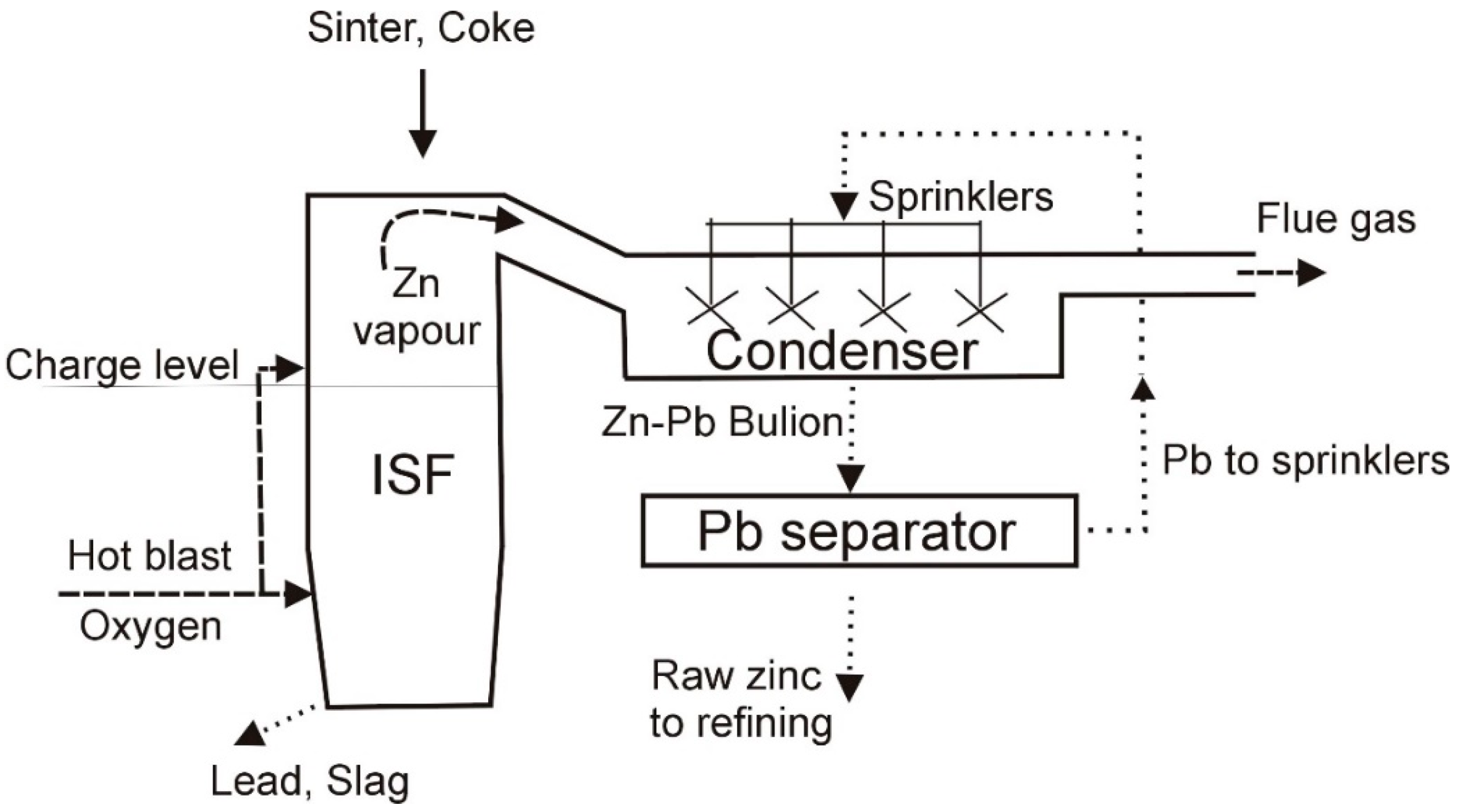
2.1. ISF Process Description

An ISF is a shaft blast furnace with a horizontal cross-section in a shape close to an oval. The charge to the ISF is a hot sinter (~300 °C) loaded directly from the sinter strand and preheated coke (~800 °C). Hot air (~1000 °C) and occasionally oxygen (for output rising) are blown through tuyeres. Coke is burned before tuyeres, and the formed gas provides the heat and carbon monoxide needed for the reduction of the zinc and lead oxides. Lead oxide is quickly reduced to a metallic state. The lead and slag are tapped from the bottom of the furnace. Zinc oxide, however, is reduced in a high-temperature zone by carbon monoxide with a mostly involved Boudouard reaction. To prevent the zinc reoxidation from cooling, a part of the hot blast (about 10%) is blown over the charge level and burns a part of the CO. Zinc vapor leaves the top of the furnace from the side and is sprinkled with the liquid lead in the condenser to obtain a condensed phase. After the lead separation, raw zinc is subjected to refining. The process diagram is shown in Figure 1.
Modelling the process in a shaft furnace, such as the ISF, requires attention to its complexity consisting of the simultaneous coexistence of three aggregate states of the liquid, solid, and gas phases, between which physicochemical processes take place. Observation of the furnace indicates its ambiguous operation in terms of mass and heat exchange processes, so mathematical modelling can help in understanding and highlighting shortcomings in ISP technology.

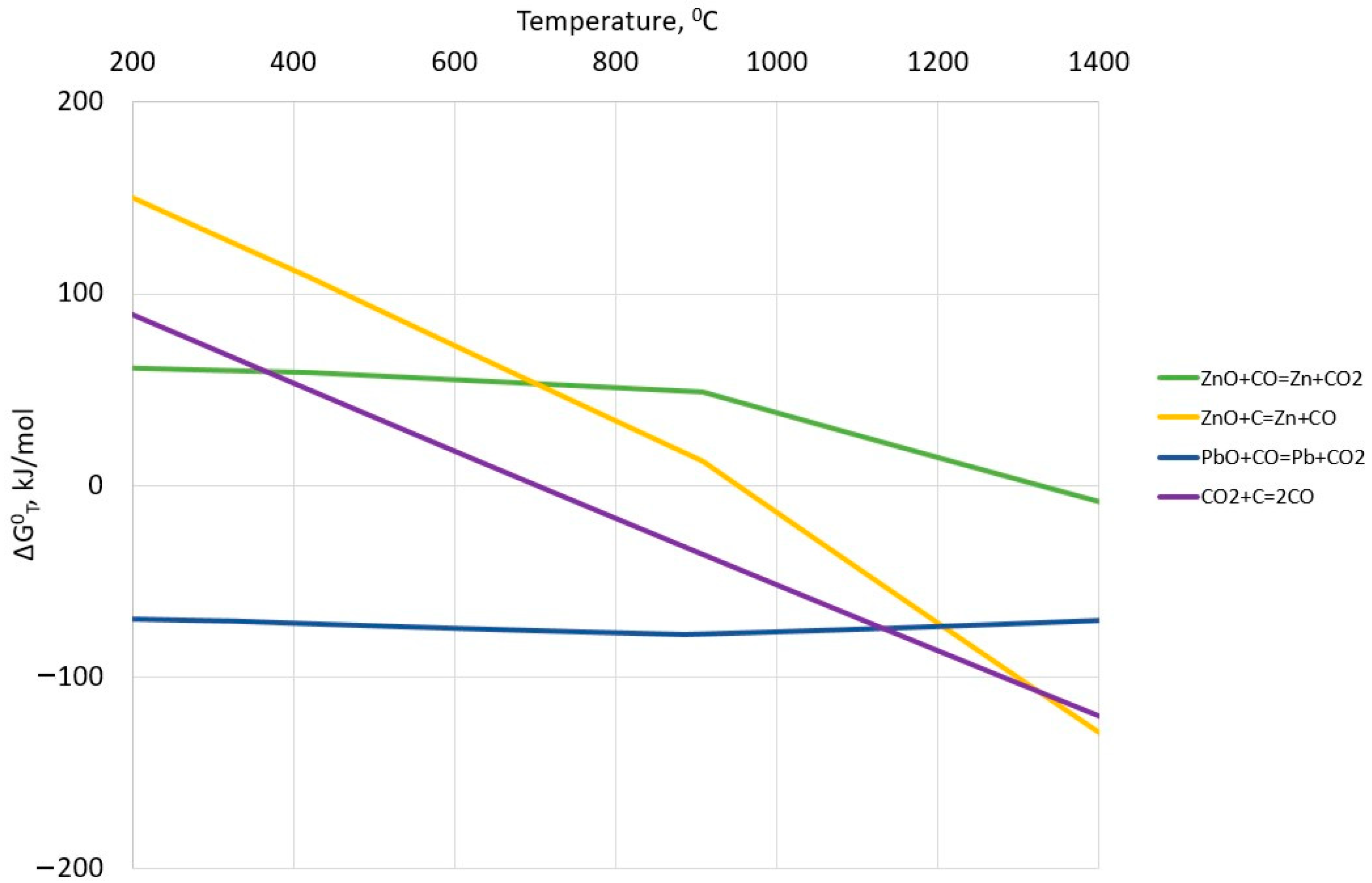
2.2. Reduction Processes in ISF

The main chemical process in an ISF is the reduction of Pb and Zn oxides contained in the sinter.
Figure 2 shows the free energy dependence on the temperature for reduction reactions taking place in the working volume of the ISF.
From Figure 2, it can be understood that it is easiest to reduce lead oxide (ΔG°T(I) < 0 in all temperature ranges), which is possible in the upper part of the furnace indirectly, according to reaction (1):
PbO + CO = Pb + CO2,
The zinc oxide reduction, however, is more demanding thermochemically.
Mostly in the presence of solid carbon deriving from coke, zinc oxide is reduced directly in two stages (2) + (3) = (4):
ZnO + CO = Zn + CO2,
CO2 + C = 2CO
ZnO + C = Zn + CO
Reaction (4) is possible to proceed at the temperature range above 900 °C when ΔG°T(IV) < 0.
It is worth noticing that when carbon reduces the zinc oxide in reaction (4), it cannot be a source of heat in an ISF according to reaction (5):
C + 0.5O2 = CO
However, indirect reduction (2) according to Figure 2 can proceed above 1300 °C. In addition to the temperature factor in reaction (2), the gas phase composition also plays an important role, namely the share of CO and CO2 concentration. Because of fact, the Boudouard reaction (3) plays an increasingly important role in the gas phase composition over 700 °C, and the proceeding reaction (2) could not be described simply.
To take into account all the possible reactions that proceeded simultaneously in ZnO reduction processes in the ISF, we carried out thermochemical calculations. Calculations were performed by using the FactSage thermochemical software and databases. Table 1 shows the software setting for calculation performance. Because reactions (1)–(5) present mostly equilibrium for 1 mol for each substance, ingredients input also are 1 mol each. Calculations were performed in the range of 200–1400 °C in step 1.
Figure 3 shows all stable phases in equilibrium, and Figure 4 shows the gas-phase composition dependence on the temperature.
It can be seen that at low temperatures there is only a reaction between C, CO, and CO2 according to the inverted Boudouard reaction (3), namely the Bell reaction (6):
CO = C + CO2
Only after raising the temperature over 800 °C does the ZnO reduction start. It should be noted that zinc as a product appears only as a gas phase.
Figure 5 shows gas-phase reduction ability expressed by the quotient of reductive ingredients sum to all gas-phase sum η CO + Zn = % CO + % Zn % CO + % Zn + % CO 2 dependent upon the temperature (orange curve). From the route of the orange equilibrium curve, it is not clear when zinc reduction begins. Inflexion points are only visible after exceeding the temperature of 900 °C; however, in Figure 3 and Figure 4, it can be seen that the zinc presence is already between 800 °C and 900 °C. It was decided to chart the dependence curve in a different arrangement—by quotient η CO = % CO % CO + % Zn + % CO 2 on the temperature. It presents the blue curve in Figure 5.
From the route of the blue equilibrium curve, the ranges of character reduction processes of ZnO can be seen. So, at 837 °C there is a maximum value of quotient η CO due to increased Zn and CO2 in the gas phase; thus, indirect reduction according to reaction (II) is started and lasts until 901 °C. In range 901–928 °C, Zn is still increased, but CO2 drops; thus, the types of reduction—indirect and direct—take place there. Over 928 °C, CO2 is completely absent in the gas phase because of its consumption by the Boudouard reaction (III). There is only direct reduction can take place according to the mechanism (II) + (III) = (IV). The read value of quotient η CO + Zn = 0.9367 at the temperature 837 °C shown in Figure 5 means an equilibrium of the gas phase at the start of ZnO indirect reduction. It is necessary for building the fuel consumption minimization model.

2.3. Fuel Rate Minimization Model Construction

The principles of the optimal division of direct and indirect reduction in ironmaking blast furnaces (IBFs) are based on the theory of A.N. Ramm, who first noticed the dependence of coke consumption on the share of wustite direct and indirect reduction. A support algorithm for fuel consumption optimization was successfully implemented in blast furnace practice [28,29]. The shared principles of optimal direct reduction rate (dDR) and indirect reduction rate (dIR) adopted to ISP technology are shown in Figure 6.
The diagram is built on heat and chemical demands. The boundary conditions are calculated for 100% indirect and 100% direct reduction, although in a real ISF the reduction of ZnO occurs in both directions.
The ordinates of points ‘1′ and ‘4′ respond to carbon demands at dIR = 100% and dDR = 100%, respectively. However, the ordinates of ‘2′ and ‘3′ rule the course of straight lines ‘A’ and ‘B’, respectively. The slope of ‘A’ reflects the carbon requirement decrease due to the lowering of chemical requirements, while the slope of ‘B’ reflects the lowering of thermal requirements. The intersection of the lines at point ‘O’ shows the minimum carbon rate at the optimal share of both types of ZnO reduction. The line running according to points 1-O-4 is the boundary, below which ISF operation is not possible.
According to Figure 5, the start of ZnO indirect reduction is possible when the reduction ability of the gas phase expressed by quotient η CO + Zn for reaction (2) will be at least 0.9367. It means that the reaction must be carried out with an excess of CO. Thus, for 1 mol of zinc, reaction (2) should be written:
1ZnO + (x + 1)CO = 1Zn + 1CO2 + xCO
To prevent reverse oxidation of the zinc vapours with the resulting CO2, the right-hand side of reaction (7) must satisfy the condition (8):
η CO + Zn = CO + Zn CO + Zn + CO 2 0.9367
So, the x in reaction (7) can be calculated from (9):
x + 1 x + 1 + 1 = 0.9367
x = 13.78
Thus, irreversible ZnO indirect reduction starts when the amount of CO is at least 14.78 mol per 1 mol of produced Zn. It means that the carbon needed to obtain CO is calculated stoichiometrically according to (11):
M C IR = 12 65.4 · 14.78 · 1000 = 2711 kg C / tZn
where 12 and 65.4 are the molar masses of carbon and zinc, respectively.
However, ZnO direct reduction according to reaction (IV) does not need the excess of CO, because no CO2 is produced, and carbon needs for reduction can be calculated as (12):
M C DR = 12 65.4 · 1000 = 183.5 kg C / tZn
Taking into account what was mentioned before, the ordinates of points 1, 2, 3, and 4 in Figure 6 can be calculated as:
y 1 = 2711
y 2 = 183.5
y 3 = Q Zn + Q slag + Q Pb + Q tg + Q CL Q HB Q C 700 Q S 200 9.196
y 4 = 183.5 + 240 × 10 3 65.4 × 10 6 · 1 9.196 + y 3
where:
  • QZn—zinc enthalpy, MJ/tZn;
  • Qslag—slag enthalpy, MJ/tZn;
  • QPb—lead enthalpy, MJ/tZn;
  • Qtg—top gas enthalpy, MJ/tZn;
  • QCL—cooling losses, MJ/tZn;
  • QHB—hot blast enthalpy, MJ/tZn;
  • QC700—coke enthalpy at 700 °C, MJ/tZn;
  • QS200—sinter enthalpy at 200 °C, MJ/tZn;
  • 240 × 10−3—enthalpy of endothermic reaction (IV), MJ/mol Zn;
  • 65.4 × 10⁻⁶—molar mass of zinc, t/mol;
  • 9.196—enthalpy of exothermic reaction (V), MJ/kg C.
It should be noted that according to Equation (17), for every 1% greater than optimal dDR, the overall coke consumption is increased by about 6.65 kg/tZn:
CR = d DR 100 y 4 y 3 100 88
where:
  • CR—coke rate, kg/tZn;
  • 88—average carbon content in coke, mass %.
On the other hand, according to (18), for every 1% lower than optimal dDR, the overall coke consumption increases to 28.7 kg/tZn:
CR = d DR 100 y 1 y 2 100 88

2.4. Calculation of ISF Output

The complexity of the winning process, where products move through several phases, does not allow us to determine precisely the main product stream mass in a short period. The accuracy of determining the mass of main products in an ISP is more accurate the longer the time for which they are evaluated: shift, day, month. However, for the proper regulation of the process and especially for the control of the coke supply dependent upon its demand, it is necessary to determine the masses of output in a shorter period such as an hour.
Figure 7 shows material streams in an ISP on which is based the calculation of the ISF output. From the top are charged sinter and coke. These materials are precisely weighted. By-products as scale gathered from the condenser well and black sludge from the off-gas filter are estimated daily in kg per tonne of raw zinc. In addition, lead in the condenser (sprinkled lead) must be supplemented with about 70–80 kg/tZn.
The unknown parameters in this system are the masses of raw zinc, raw lead, and slag. These unknowns can be found by a solution of a system of three linear equations describing the material balance for Zn, Pb, and SiO2:
Zinc balance:
% Zn sin ter · M sin ter = % Zn slag · M s l a g + % Zn zinc · M z i n c + % Zn lead · M l e a d   + + % Zn scale · M scale + % Zn sludge · M sludge
Lead balance:
% Pb sin ter · M sin ter + 100 · M sprinkled lead = = % Pb slag · M s l a g + % Pb zinc · M z i n c + % Pb lead · M l e a d + % Pb scale · M scale + % Pb sludge · M sludge
SiO2 balance:
% SiO 2 sin ter · M sin ter + % SiO 2 coke · M coke = = % SiO 2 slag · M s l a g + % SiO 2 scale · M scale + % SiO 2 sludge · M sludge
where:
  • %Zn, %Pb, %SiO2—weight percent of element or substance, wt.%;
  • M—a mass of stream per charge, kg;
Bold parameters are unknown.
The solution of the Equations (19)–(21) system allows for the calculation of demanded batch material masses and thus adjusts the fuel consumption according to the fuel rate minimization model. There is also the possibility of the main product masses calculation obtained after actual charging.

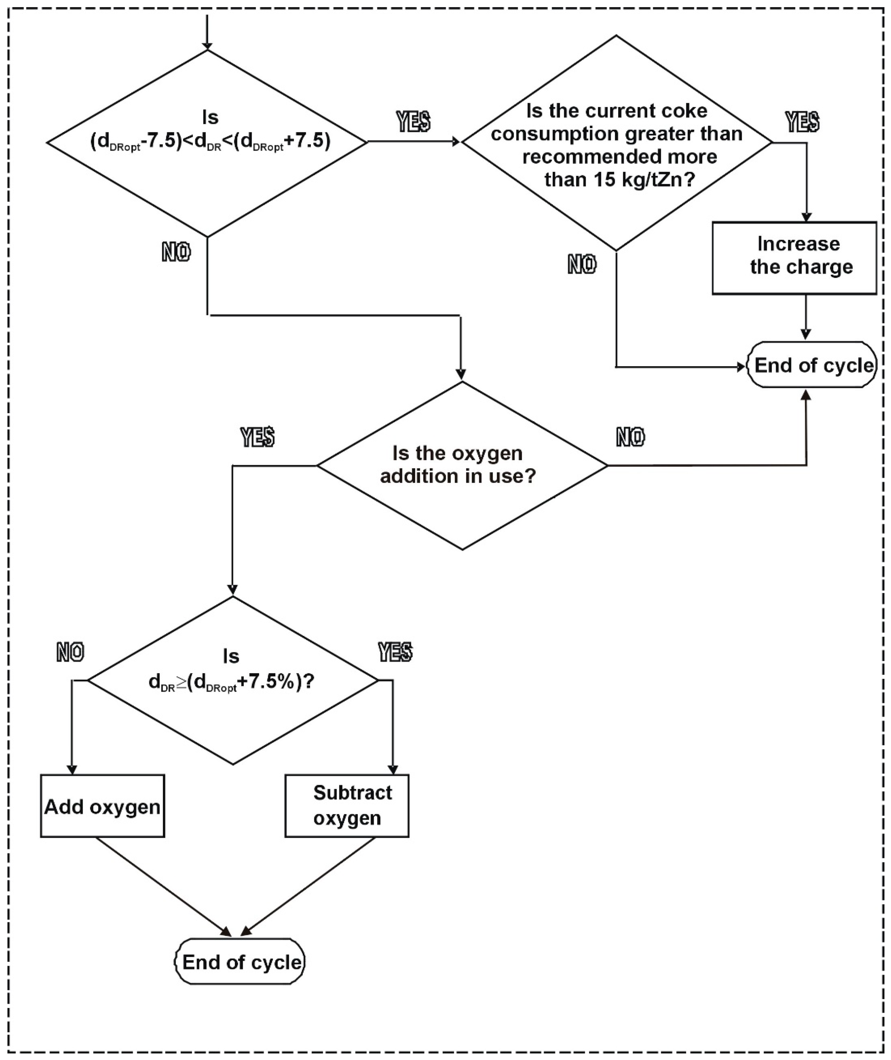
3. Results of Model Implementation and Discussion

Figure 8 shows the fuel rate minimization model built on real data. Carbon requirement is recalculated for dry coke consumption, which is a more convenient parameter.
In addition, Figure 8 shows the following:
  • The ISF operating point, which reflects current coke consumption at the actual direct reduction rate;
  • Boundaries of optimal direct ZnO reduction rate; they are set as ±7.5% deviation from the optimal direct reduction rate (two vertical blue lines);
  • Results of the fuel rate minimization model, as current coke rate at the current dDR, recommended coke rate, and also theoretical minimum coke rate at the optimal dDR.
Thus, the best position for the ISF operation point is exactly under the intersection point of the red and black lines. This can be achieved by adjusting the oxygen additive in the hot blast. It is hard to achieve the exact amount of additives, so the range of the optimal direct reduction rate is set to optimal dDR ± 7.5%. This range of deviation is appropriate for oxygen addition or when even blast addition is not used. Figure 8 also shows the operation point situation dependence on the regulation factors. Oxygen addition causes a lowering of direct reduction; however, subtracting increases dDR.
However, adjusting the operation point vertically can be realized by top feed charge changing. Unloading of the sinter (increasing of C/Zn) causes the operating point to move upward. Burdening of the sinter (decreasing of C/Zn) causes the operating point to move downward, which directly influences fuel consumption lowering.
Figure 8 also presents the results of calculated characteristics such as the recommended coke rate, theoretical minimal coke rate, and optimal direct reduction rate. The theoretical minimal fuel rate is calculated at the optimal direct reduction rate (dDRopt), and it is hard to achieve because the operating point will be placed in a narrow heat-state area of the ISF. Thus, the recommended coke rate is a more convenient and safer parameter that could be regulated by top charge changing.
Figure 9 presents the detailed algorithm of ISF regulation by the fuel rate minimization model per one-hour cycle.
Firstly, the model checks if the operating point of the furnace is placed between vertical blue lines. If not, it is recommended to adjust the oxygen addition. The addition of oxygen deteriorates the direct reduction rate; however, subtracting oxygen does so inversely. If the oxygen addition is not in use currently, the regulation cycle is ended. In contrast, if the operation point is placed in the area dDRopt ±7.5%, and the current coke consumption is greater than 15 kg/tZn, the model recommends increasing the charge according to (22):
C / Zn recom = C / Zn current · P ch C ch CR recom C ch CR current P ch + C / Zn current · 1 2
where:
  • C/Znrecom—top charge recommended to use in next hour;
  • C/Zncurrent—current top charge;
  • Pch—charge production tZn/charge;
  • Cch—coke input, kg/charge;
  • CRrecom—recommended coke rate, kg/tZn;
  • CRcurrent—current coke rate, kg/tZn.
Data from about one month of ISF work were gathered for model testing. During industrial testing of the model, there was no possibility to test the oxygen addition. The oxygen was not used for a long period due to the current market condition (oxygen addition increases the ISF output). Table 2 presents the average monthly working parameters and calculated characteristics. As it can be seen, the furnace can be operated with coke consumption of more than 30 kg/tZn lower than the current. It can be achieved by lowering the top charge expressed by quotient C/Zn, namely by increasing the sinter mass in the charge.

4. Conclusions

The purpose of the work was the construction of a tool that allows us to highlight shortcomings in zinc blast furnace operation while online and counter them with fuel consumption optimization. The work consisted of the following stages:
  • Thermochemical analysis of reduction processes necessary for the determination of boundary conditions to build the fuel rate minimization model;
  • Construction of the model using A.N. Ramm’s principles of direct and indirect reduction share;
  • Calculation of current zinc production in tonne per charge, what is necessary to unify material input and output streams;
  • Development of regulatory recommendations that will affect the optimization of fuel consumption.
Verification of the model in real conditions showed that the referenced zinc blast furnace could be operated with fuel consumption lower than 30 kg of coke per tonne of zinc.
As a result, the blast furnace crew received a simple tool that allows hourly determination of the correctness of the furnace operation and possible necessary adjustments.

Author Contributions

Conceptualization, M.B. and R.S.; methodology, R.S.; software, M.B.; validation, A.K. and M.B.; formal analysis, M.B.; investigation, A.K.; resources, A.K.; data curation, M.B.; writing—original draft preparation, M.B.; writing—review and editing, R.S.; visualization, A.K.; funding acquisition, M.B., R.S. and A.K. All authors have read and agreed to the published version of the manuscript.

Funding

This research was funded by European Regional Development Fund, Operational Programme Smart Growth 2014–2020, Sectoral Programme INNOSTAL, project no. POIR.01.02.00-00-0174/16.

Data Availability Statement

The data presented in this study are available on request from the corresponding author.

Acknowledgments

Authors are grateful to the workers of HCM for supporting the project.

Conflicts of Interest

The authors declare no conflict of interest.

References

  1. Śmieszek, Z.; Czernecki, J.; Sak, T.; Madej, P. Metallurgy of non-ferrous metals in Poland. J. Chem. Technol. Metall. 2017, 52, 221–234. [Google Scholar]
  2. Patil, S.B.; Vyas, A.K.; Gupta, A.B.; Patil, R.S. Imperial smelting furnace slag as fine aggregate in cement concrete mixes. J. Solid Waste Technol. Manag. 2016, 42, 128–136. [Google Scholar] [CrossRef]
  3. Szweda, Z.; Ponikiewski, T.; Katzer, J. A study on replacement of sand by granulated ISP slag in SCC as a factor formatting its durability against chloride ions. J. Clean. Prod. 2017, 156, 569–576. [Google Scholar] [CrossRef]
  4. Patil, S.B.; Vyas, A.K.; Gupta, A.B. Utilization of an industrial waste in cement concrete mixes. J. Solid Waste Technol. Manag. 2014, 40, 79–85. [Google Scholar] [CrossRef]
  5. Banerjee, A.; Sen, P.K.; Roy, S.K. Novel approach to modeling of imperial smelting furnace behavior. Miner. Process. Extr. Metall. Rev. 2007, 28, 159–176. [Google Scholar] [CrossRef]
  6. Ebrahim, H.A.; Jamshidi, E. Kinetic study and mathematical modeling of the reduction of ZnO-PbO mixtures by methane. Ind. Eng. Chem. Res. 2005, 44, 495–504. [Google Scholar] [CrossRef]
  7. Hu, Z.K.; Yin, L.Z.; Chen, Z.W.; Gui, W.H.; Yang, C.H.; Peng, X.Q. An efficient multi-PCA based on-line monitoring scheme for multi-stages imperial smelting process. Int. J. Control Autom. Syst. 2013, 11, 317–324. [Google Scholar] [CrossRef]
  8. Straka, R.; Bernasowski, M.; Klimczyk, A.; Stachura, R.; Svyetlichnyy, D. Prediction of raceway shape in zinc blast furnace under the different blast parameters. Energy 2020, 207, 118153. [Google Scholar] [CrossRef]
  9. Małecki, S.; Gargul, K.; Warzecha, M.; Stradomski, G.; Hutny, A.; Madej, M.; Dobrzyński, M.; Prajsnar, R.; Krawiec, G. High-performance method of recovery of metals from eaf dust—Processing without solid waste. Materials 2021, 14, 6061. [Google Scholar] [CrossRef]
  10. Xue, Y.; Hao, X.; Liu, X.; Zhang, N. Recovery of Zinc and Iron from Steel Mill Dust—An Overview of Available Technologies. Materials 2022, 15, 4127. [Google Scholar] [CrossRef]
  11. Brunelli, K.; Dabalà, M. Ultrasound effects on zinc recovery from EAF dust by sulfuric acid leaching. Int. J. Miner. Metall. Mater. 2015, 22, 353–362. [Google Scholar] [CrossRef]
  12. Xin, C.; Xia, H.; Jiang, G.; Zhang, Q.; Zhang, L.; Xu, Y. Studies on Recovery of Valuable Metals by Leaching Lead–Zinc Smelting Waste with Sulfuric Acid. Minerals 2022, 12, 1200. [Google Scholar] [CrossRef]
  13. Yan, H.; Chai, L.; Peng, B.; Li, M.; Peng, N.; Hou, D. A novel method to recover zinc and iron from zinc leaching residue. Miner. Eng. 2014, 55, 103–110. [Google Scholar] [CrossRef]
  14. Li, H.; Saxén, H.; Liu, W.; Zou, Z.; Shao, L. Model-based analysis of factors affecting the burden layer structure in the blast furnace shaft. Metals 2019, 9, 1003. [Google Scholar] [CrossRef] [Green Version]
  15. Zhou, H.; Wu, S.; Kou, M.; Luo, Z.; He, W.; Zou, Z.; Shen, Y. Discrete particle simulation of solid flow in a large-scale reduction shaft furnace with center gas supply device. ISIJ Int. 2018, 58, 422–430. [Google Scholar] [CrossRef] [Green Version]
  16. Ariyama, T.; Natsui, S.; Kon, T.; Ueda, S.; Kikuchi, S.; Nogami, H. Recent progress on advanced blast furnace mathematical models based on discrete method. ISIJ Int. 2014, 54, 1457–1471. [Google Scholar] [CrossRef] [Green Version]
  17. Shatokha, V.; Velychko, O. Study of softening and melting behaviour of iron ore sinter and pellets. High Temp. Mater. Process. 2012, 31, 215–220. [Google Scholar] [CrossRef]
  18. Small, J.; Adema, A.; Andreev, K.; Zinngrebe, E. Petrological study of ferrous burden-crucible interaction in softening & melting experiments: Implications for the relevance of pressure drop measurements. Metals 2018, 8, 1082. [Google Scholar] [CrossRef] [Green Version]
  19. Bernasowski, M.; Klimczyk, A.; Stachura, R. Calculation of coke layers situation in the cohesive zone of blast furnace. Materials 2021, 14, 192. [Google Scholar] [CrossRef]
  20. Hou, Q.; Dianyu, E.; Kuang, S.; Yu, A. A Transient Discrete Element Method-Based Virtual Experimental Blast Furnace Model. Steel Res. Int. 2020, 91, 106369. [Google Scholar] [CrossRef]
  21. Guha, M. Revealing cohesive zone shape and location inside blast furnace. Ironmak. Steelmak. 2018, 45, 787–792. [Google Scholar] [CrossRef]
  22. Kuang, S.; Li, Z.; Yu, A. Review on Modeling and Simulation of Blast Furnace. Steel Res. Int. 2018, 89, 1700071. [Google Scholar] [CrossRef]
  23. Kexin, J.; Jianliang, Z.; Chunlin, C.; Senran, W.; Lisheng, L. Analysis of the deadman features in hearth based on blast furnace dissection by comprehensive image-processing technique. ISIJ Int. 2019, 59, 16–21. [Google Scholar] [CrossRef] [Green Version]
  24. Okosun, T.; Silaen, A.K.; Zhou, C.Q. Review on Computational Modeling and Visualization of the Ironmaking Blast Furnace at Purdue University Northwest. Steel Res. Int. 2019, 90, 1353–1362. [Google Scholar] [CrossRef]
  25. Zhou, C.; Tang, G.; Wang, J.; Fu, D.; Okosun, T.; Silaen, A.; Wu, B. Comprehensive Numerical Modeling of the Blast Furnace Ironmaking Process. JOM 2016, 68, 1353–1362. [Google Scholar] [CrossRef]
  26. Kardas, E.; Prusak, R. The assessment of efficiency of work of blast furnace. Metalurgija 2020, 59, 403–406. [Google Scholar]
  27. Hashimoto, Y.; Masuda, R.; Mulder, M.; van Paassen, M.M. (René) Automatic Control of Hot Metal Temperature. Metals 2022, 12, 1624. [Google Scholar] [CrossRef]
  28. Bernasowski, M.; Klimczyk, A.; Stachura, R. Support algorithm for blast furnace operation with optimal fuel consumption. J. Min. Metall. Sect. B Metall. 2019, 55, 31–38. [Google Scholar] [CrossRef] [Green Version]
  29. Bernasowski, M.; Ledzki, A.; Stachura, R.; Klimczyk, A. Basic structure of the fuel rate optimization model and its practical use at the blast furnace technology. In Proceedings of the METAL 2014: 23rd International Conference on Metallurgy and Materials, Brno, Czech Republic, 21–23 May 2014; pp. 39–44. [Google Scholar]
  30. Brožová, S.; Jursová, S.; Pustejovská, P.; Bilík, J. Kinetics of reduction and oxidation reactions during pyrometallurgical metal extraction. Sci. Iran. 2017, 24, 2009–2018. [Google Scholar] [CrossRef]
Figure 1. The ISF working diagram.
Energies 15 09259 g001
Figure 2. Free Gibbs energy in the temperature dependence for the main reaction in ISP.
Energies 15 09259 g002
Figure 3. Equilibrium of all stable phases dependent upon the temperature.
Energies 15 09259 g003
Figure 4. Equilibrium of gas phases dependent upon the temperature.
Energies 15 09259 g004
Figure 5. Gas-phase-reducing ability dependent upon the temperature for ZnO-CO-C.
Energies 15 09259 g005
Figure 6. Carbon rate–ZnO reduction ratio diagram.
Energies 15 09259 g006
Figure 7. Material streams in an ISF.
Energies 15 09259 g007
Figure 8. View of the fuel rate minimization model working on real data.
Energies 15 09259 g008
Figure 9. Operation point adjustment by fuel rate minimization model in a one-hour cycle.
Energies 15 09259 g009
Table 1. Software setting for equilibrium calculations of ZnO reduction processes.
Ingredient Input, molPossible Substances in Equilibrium
1ZnO(s) * + 1CO(g) + 1C(s)ZnO(s), ZnO(liq), Zn(s), Zn(liq), Zn(g),
CO(g), CO2(g), C(s)
* (s)–solid phase, (liq)–liquid phase, (g)–gas phase.
Table 2. Measured and calculated characteristics used in the model verification.
Group of VariablesVariable NameValueUnit
Measured characteristicsSinter input
Coke input
Hot blast input
Hot blast temperature
CO in flue gas
CO2 in flue gas
Top gas temperature
2932
1195
36,248
1053
28.42
7.16
918
kg/charge
kg/charge
m3/h
°C
vol.%
vol.%
°C
Calculated characteristics
of heat balance in Equation (8)
QZn
Qslag
QPb
Qtg
QCL
QHB
QC700
QS200
2281
606
−32 *
5030
1670
4355
1194
377
MJ/tZn
Calculated characteristics of the fuel rate minimization modelCurrent direct reduction rate, dDR
Charge production, Pch
Current coke rate, CRcurrent
Recommended coke rate, CRrecom
Current top charge, C/Zncurrent
Recommended top charge, C/Znrecom
74.53
1.18
1013
980
0.863
0.848
%
tZn/charge
kg/tZn
kg/tZn
-
-
* The negative value for QPb results from the fact that the PbO reduction enthalpy is higher than Pb preheating to the tap temperature.
Publisher’s Note: MDPI stays neutral with regard to jurisdictional claims in published maps and institutional affiliations.

