Article

A Study on Reduction of Cogging Torque and Magnet Usage through Intersect Magnet Consequent Pole Structure

1
Department of Electrical Engineering, Hanyang University, Seoul 133-791, Republic of Korea
2
Department of Electrical Engineering, Gachon University, Seongnam 461-701, Republic of Korea
*
Author to whom correspondence should be addressed.
Energies 2022, 15(23), 9255; https://doi.org/10.3390/en15239255
Submission received: 21 October 2022 / Revised: 25 November 2022 / Accepted: 1 December 2022 / Published: 6 December 2022

Abstract

:
Owing to the shortage of rare-earth magnetic materials, various methods are being examined to reduce the use of magnets. One of these is a consequent pole. The consequent pole model can reduce the use of magnets by 50% using only one pole of the magnet and replacing the other pole with iron. However, the consequent pole has the disadvantage of generating back EMF asymmetry and a high cogging torque. In this study, an intersect magnet consequent pole structure is proposed to overcome the disadvantages of the existing consequent pole. Two methods have been proposed to improve axial leakage magnetic flux caused by the intersect magnet consequent pole structure. Finally, we propose a method to reduce the cogging torque and minimize the use of magnets with the same performance standard. For motor design, two-dimensional and three-dimensional finite element analysis was used, and comparative analysis was performed via simulations for several models. The existing model and the final model were compared and verified.

1. Introduction

Permanent magnet synchronous motors are used in many industrial fields owing to their high efficiency and performance [1,2,3,4,5,6]. However, owing to the scarcity of rare-earth magnetic materials, the price of NdFeB magnets is gradually increasing. Therefore, it is difficult to popularize and develop permanent magnet synchronous Motor (PMSM). To solve this problem, many studies have been conducted to develop a motor that excludes rare-earth magnets [7,8,9]. However, magnets that do not contain rare-earth elements exhibit poor performance. Therefore, it is difficult to achieve the target performance. For this reason, although NdFeB magnets are used, numerous studies have been conducted to minimize their use. One such study is on the consequent pole (CP) [10,11,12,13]. The consequent pole uses only one pole, and the other pole is composed of iron; therefore, the use of magnets can be reduced by 50%. However, as much as the use of magnets is halved, performance degradation occurs. In addition, because the structure uses only one pole, back EMF asymmetry and a high cogging torque occur [14,15,16]. In this study, a motor for electric power steering (EPS) was selected and designed as an existing model; an intersect magnet consequent pole that can improve the disadvantages of the consequent pole and minimize the use of magnets is proposed. The intersect magnet consequent pole is a model that combines the upper and lower halves with the stacked half of the existing CP rotor as the N pole CP, and the other half as the S pole CP. Thus, it is possible to overcome the disadvantages of existing CPs with symmetry in the upper and lower halves of the rotor. However, in the intersect magnet CP, a large axial leakage magnetic flux occurs between the upper and lower halves of the rotor, resulting in a significant performance degradation. To improve this, two methods are proposed in this study. The first involves creating a gap between the upper and lower halves of the rotor, known as the rotor gap. It is then possible to reduce the axial leakage magnetic flux; however, it is difficult to expect a large performance improvement. Therefore, the second method, that is, inserting a magnet into the rotor gap, was proposed. If a center magnet is inserted, the leakage magnetic flux generated between the upper and lower halves of the rotor can be reduced, and the performance can be significantly improved by acting as a magnet concentration structure. Subsequently, the cogging torque and magnet usage can be reduced based on the same performance standard. In this study, a comparative analysis was performed using two-dimensional (2D) and three-dimensional (3D) finite element analysis (FEA), and the validity of the proposed model was verified by comparing it with the simulation results.

2. Consequent Pole Applied to Reduce Magnet Usage

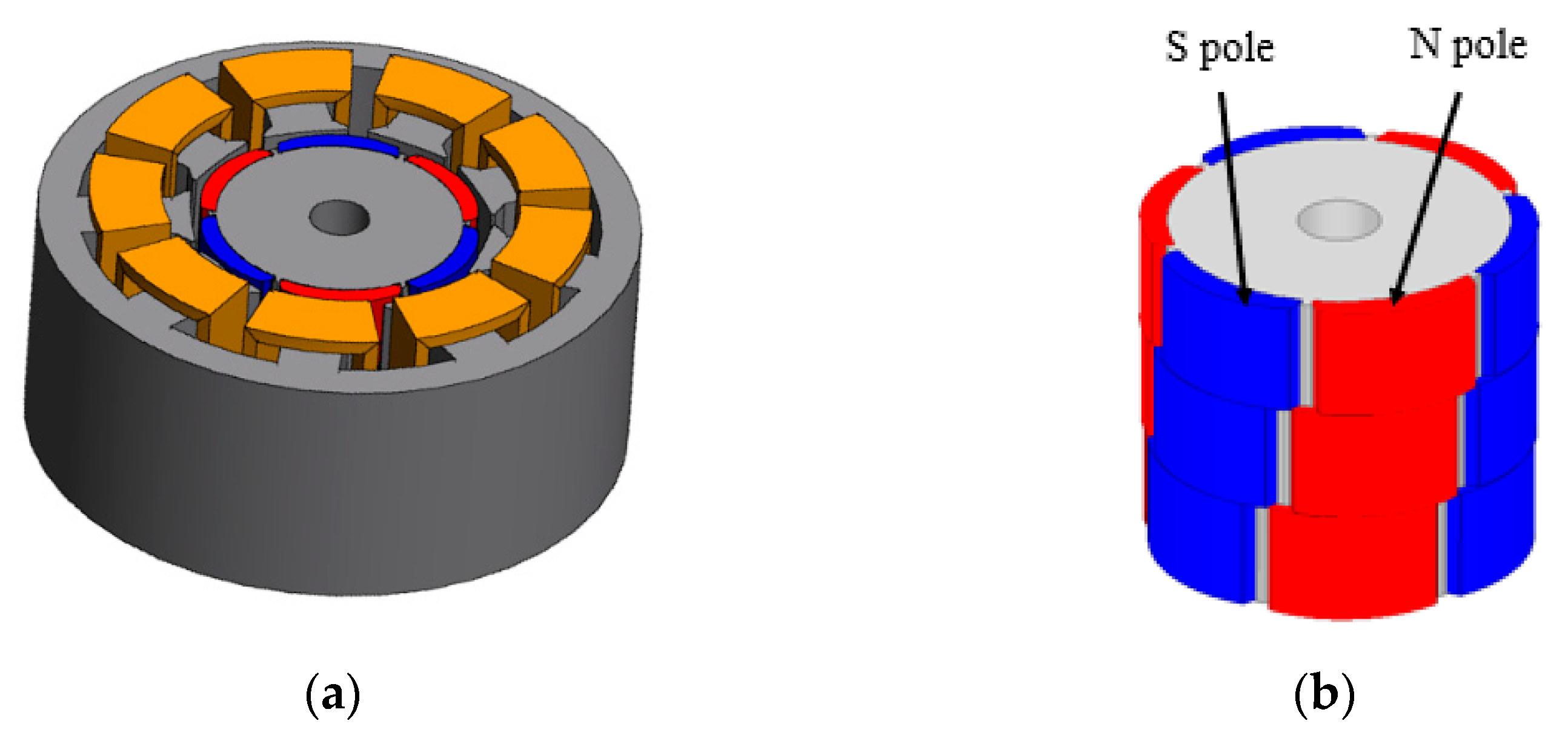
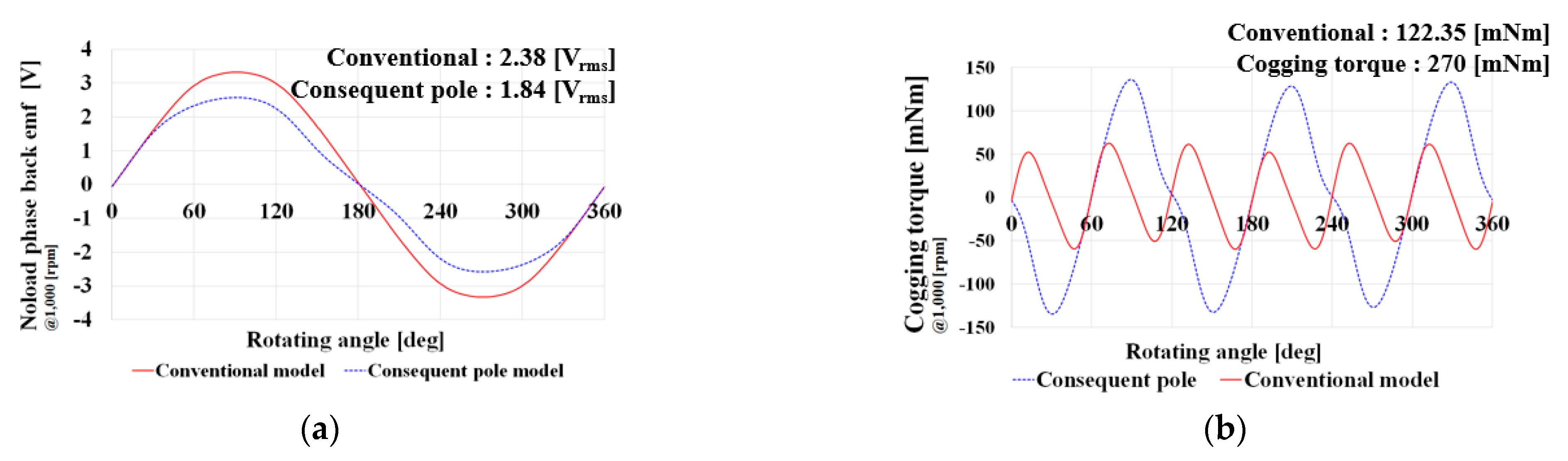
2.1. Existing Model Analysis

Figure 1 illustrates the permanent magnet motor for the EPS and existing model. In the existing model, 3-stage skew of the rotor is applied to reduce the cogging torque. The cogging torque can be reduced by applying a skew structure to the rotor. The cogging torques generated in the 1st, 2nd, and 3rd stages of the rotor skew are combined and cancel each other out. Therefore, the cogging torque can be reduced. However, manufacturing is difficult. Table 1 presents the performance and specifications of the proposed model.

2.2. Consequent Pole

In this study, the consequent pole was applied to the existing model to reduce the use of magnets. Consequently, the total use of magnets can be reduced by 50% by removing the N and S poles of the magnet inserted into the rotor, using only one pole, and replacing the remaining pole with iron. Figure 2 depicts the rotor shape and magnetic flux lines of the conventional and consequent pole models.
As shown by the magnetic flux line in Figure 2, it can be confirmed that the magnetic flux flows the same in the existing model and the consequent pole model. However, because the consequent pole model does not use one magnet pole, it was found that the maximum size of the magnetic flux is 0.0066 (Wb/m), which is smaller than the 0.008 (Wb/m) of the existing model. Figure 3 shows the back EMF and cogging-torque waveforms of the conventional model without skew and the consequent pole model. Figure 3a illustrates the back-EMF waveforms of the two models. The back EMF of the previous model was 2.38 (Vrms), and the consequent pole model decreased by 22.68% to 1.84 (Vrms). However, back-EMF asymmetry occurs in the consequent pole. When the back EMF is asymmetrically generated, controllability is reduced. Figure 3b displays the cogging-torque waveforms of the two models. As indicated in the figure, the cogging torque is high in the consequent-pole model because only one magnetic pole was used for the consequent pole. Since the cogging torque acts as the main performance parameter for EPS motors, it is essential to reduce the cogging torque and improve back EMF asymmetry.

3. Application of Intersect Magnet Consequent Pole for Performance Improvement

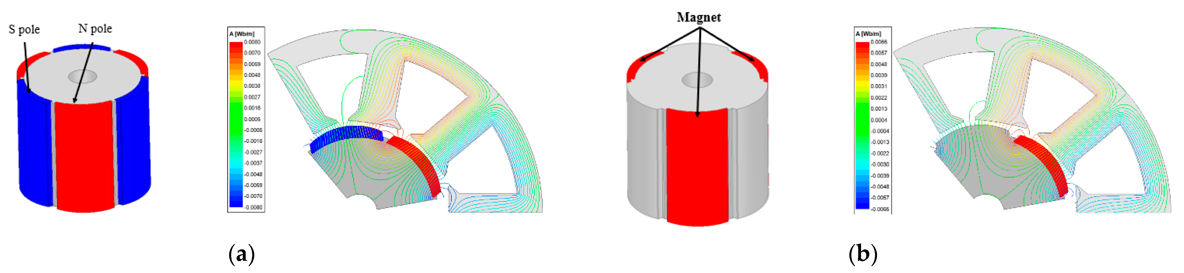
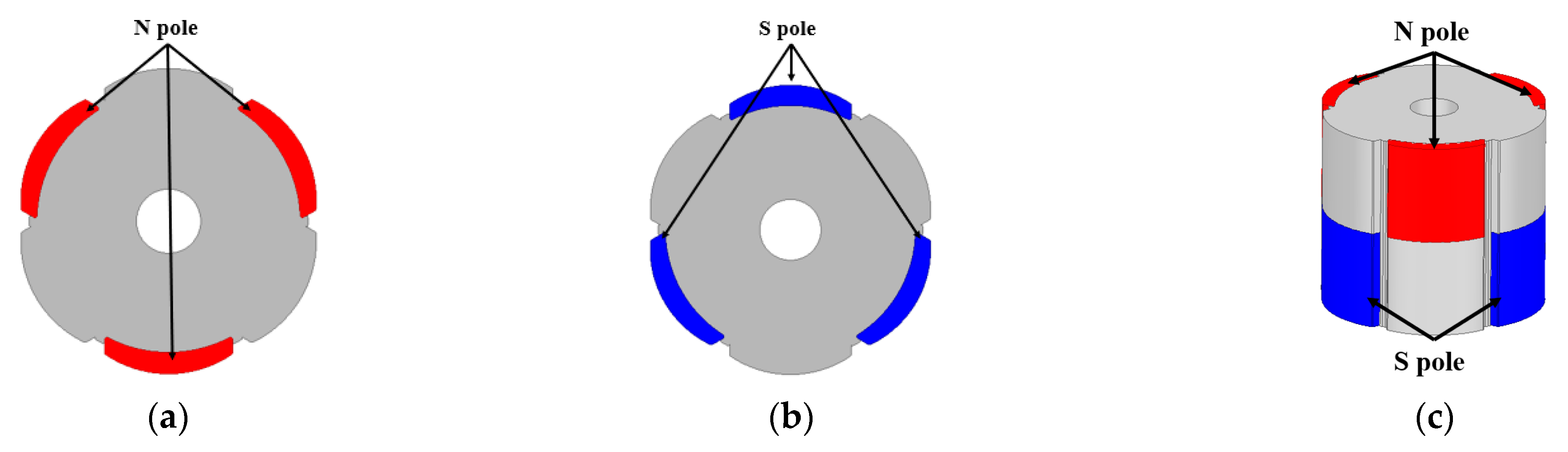
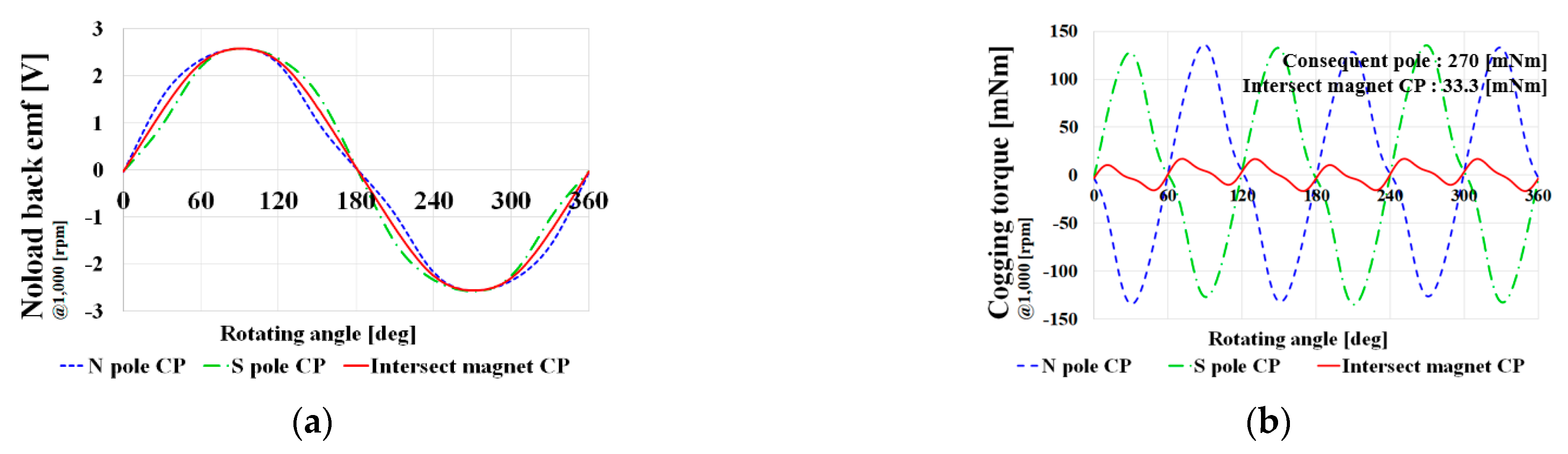
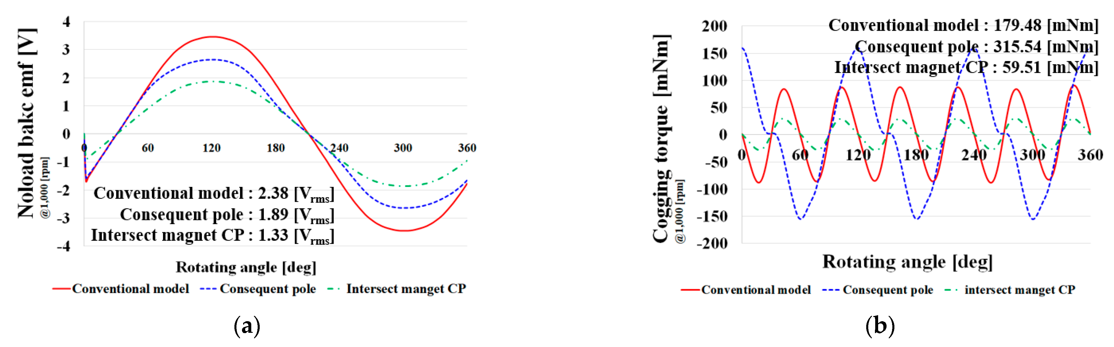
3.1. Intersect Magnet Consequent Pole

The use of magnets can be reduced by 50% by applying the existing consequent pole model. However, back EMF asymmetry and high cogging torque are considerable disadvantages. In this study, an intersect magnet consequent pole was applied to solve this problem. Figure 4 illustrates the intersection magnet consequent pole model.
Figure 4 shows the intersection magnet consequent pole model. Figure 4a presents a consequent pole rotor using an N pole, and Figure 4b shows a consequent pole using an S pole. The combined rotor is shown in Figure 4c by applying only half of each stack length. This is the consequent pole of the intersecting magnet. The upper half of the rotor is a combined model that applies the consequent pole model using the N pole and the consequent pole model using the S pole to the lower half of the rotor. By applying the intersecting magnet consequent pole, the disadvantages of the existing consequent pole model can be overcome. Figure 5 displays the back EMF and cogging-torque waveforms at each intersect magnet consequent pole.
Figure 5a shows the back EMF for N pole and S pole CP and intersect magnet CP. The back emf waveform has symmetry at N pole CP and S pole CP. Therefore, the back EMF waveform in the intersect magnet CP improves the back emf asymmetry to generate a sinusoidal waveform. Figure 5b illustrates the cogging torque waveform. The cogging torque waveform is symmetrically generated at the N pole and S pole CP; therefore, the cogging torque of the intersect magnet CP, which is a model that combines the two rotors with the upper and lower halves, is greatly reduced. More specifically, if the intersect magnet CP is developed by making half of the stack N pole CP and the other half as S pole CP is applied to the rotor, the asymmetry can be improved in the consequent pole, such as high cogging torque and back EMF asymmetry. However, the above data were performed as a 2D analysis. In other words, they is the result of neglecting the axial leakage magnetic flux. Intersect magnet CP is expected to generate large axial leakage magnetic flux between the upper half of N pole CP and the lower half of S pole CP. Therefore, 3D analysis is essential. Figure 6 depicts the noload back EMF and cogging torque waveforms of the conventional model, consequent pole model, and intersect magnet CP.
As depicted in Figure 6a, the noload back EMF of the intersect magnet CP is 1.33 (Vrms), which is 44% lower than the back EMF of 2.38 (Vrms) of the conventional model. In other words, if the intersect magnet CP is applied, the back EMF asymmetry and high cogging torque can be improved; however, the large axial leakage magnetic flux generated between the upper and lower halves of the rotor causes a significant performance degradation. Figure 7 illustrates the magnetic flux direction and magnetic flux vector of the intersecting magnet CP.
As shown in Figure 7, the magnetic flux vector of the intersect magnet CP presents the generation of a large axial magnetic flux leakage between the upper and lower halves of the rotor. As a result, performance degradation occurred.

3.2. Intersect Magnet Consequent Pole Applied with Rotor Gap

The intersect magnet consequent pole has a disadvantage in that its performance decreases owing to the large axial leakage magnetic flux. In this study, these shortcomings were addressed by separating the upper and lower halves of the rotor. There is free space in the rotor-stacking direction owing to stator end turns. To utilize the space and reduce the axial leakage magnetic flux, the rotor gap was spaced between the rotors when performing the analysis. Figure 8 illustrates the back EMF graph according to the rotor gap variable and rotor gap.
As demonstrated in Figure 8, as the rotor gap thickness increases, the performance increases up to a certain area. Thereafter, the performance decreases over a certain area. If the rotor gap thickness increases, the rotor center becomes mostly empty; therefore, the effective area of the magnet is reduced compared to the decrease in the leakage magnetic flux, and thus the performance is reduced. In other words, if the rotor gap increases, the performance increases as the axial leakage magnetic flux decreases to some extent. However, this is insufficient to satisfy the target performance.

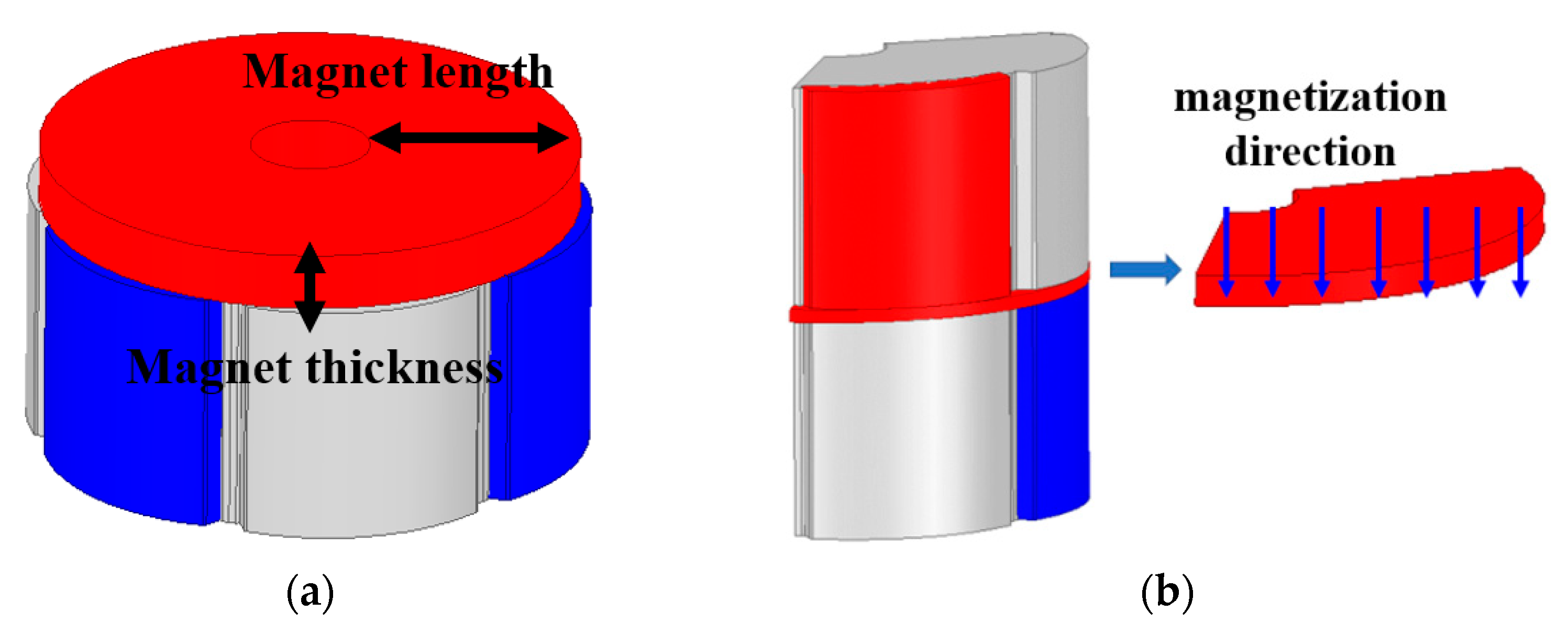
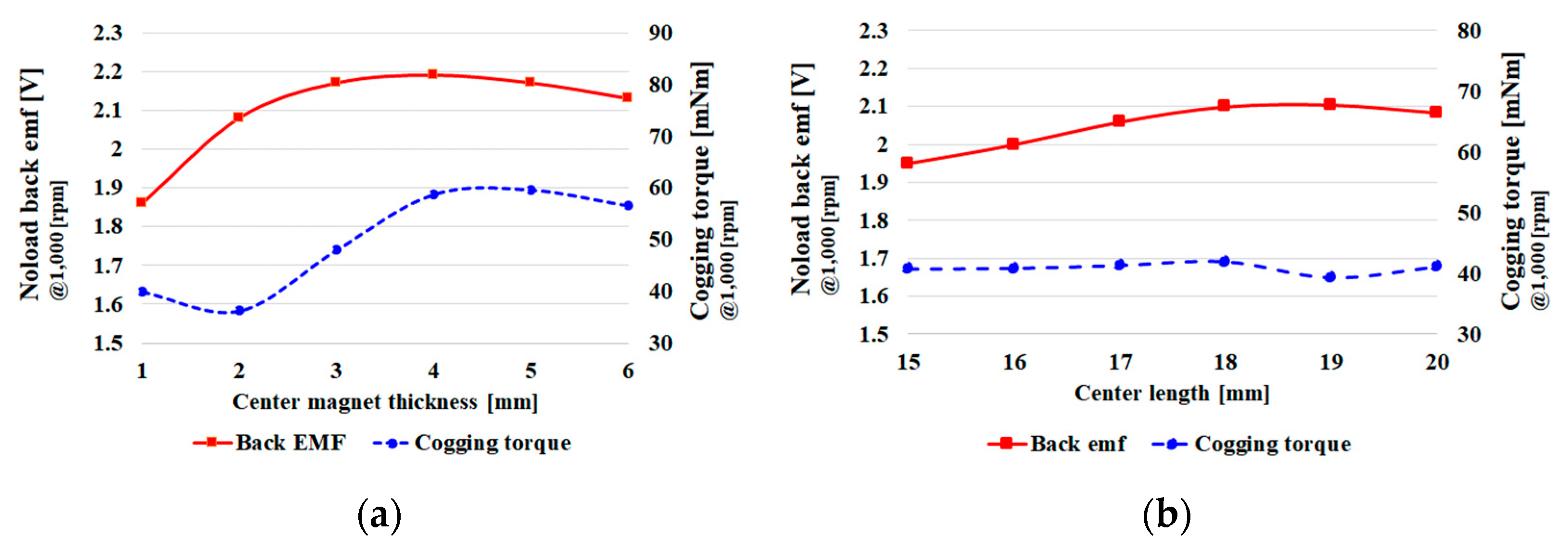
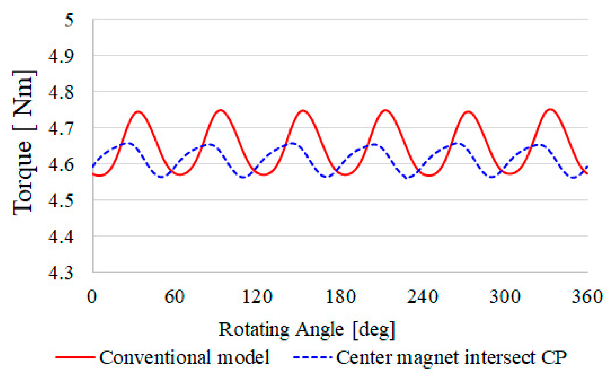
3.3. Center Magnet Applied to Intersect Magnet Consequent Pole

In this work, a model in which a magnet is inserted between the upper and lower halves of the rotor is proposed to improve the axial leakage magnetic flux in the intersecting magnet CP. Figure 9 depicts the center magnet intersecting the CP model and center magnet parameters.
As shown in Figure 9, the magnetization direction of the center magnet is set as follows: In the intersect magnet CP, leakage occurs from the lower half to the upper half of the axial leakage magnetic flux inside the rotor. A center magnet is inserted to prevent the leakage and for the structure of the magnetic flux concentration. In general PM motors, leakage magnetic flux occurs when a center magnet is inserted; however, in the case of an intersect magnet CP, the performance is improved by acting as a magnetic flux concentration shape. The optimal design was determined according to the thickness and length of the center magnet. At the time, when analyzing Figure 10a, the center magnet length was selected as 20 mm, which is the same as the rotor radius, and when analyzing Figure 10b, the center magnet thickness was selected as 2 mm. The length of the center magnet was selected as 18 mm, and the thickness was set to 2 mm. The use of magnets increased owing to the insertion; however, because the consequent pole structure was applied and the center magnet was inserted, the use of magnets decreased compared to the conventional model. Figure 11 shows back emf and cogging torque waveforms of the original model and the final model. It can be confirmed that the cogging torque is reduced with the same performance.
The models proposed in this study were analyzed in terms of torque density. The proposed models increase the stacking length because an air gap is placed between the rotors, or a magnet is inserted. Therefore, the torque density is likely to decrease; however, it does not. Although the increase in rotor stack length increases the motor volume, the increase in rotor stack length is because of the use of the rotor clearance created by the end turns of the stator windings. The power density-related formula is as follows:
P o w e r   d e n s i t y = P π ( D 2 ) 2 L × 10 6   [ kW / L ] .
where D denotes the housing outer diameter, and L indicates the housing stack length. Therefore, there was no significant change in the size of the housing because the rotor-free space generated by the end turn of the stator winding was used. Consequently, there were no significant changes in the torque density and power density. Figure 12 illustrates the torque waveforms of the two models. Referring to Figure 12, it can be observed that the final model, in which the center magnet intersects the CP model, has a small torque ripple. The torque ripple of the existing model was 0.18 (Nm), the torque ripple of the center magnet intersecting the CP model was 0.099 (Nm), and the torque ripple was reduced by 45%.

3.4. Center Magnet Intersect Consequent Pole

In this study, a center magnet intersects a consequent pole and a model that can minimize the use of magnets based on the same performance. Figure 12 presents a comparison of the back EMF and cogging-torque waveforms of the conventional model (skew model) and the final model. Table 2 presents a comparison of the electromagnetic performance and magnet usage of the conventional and final models.
As shown in Table 2, it is confirmed that the noload back EMF was almost the same and the cogging torque was reduced by 45.4% from 90 (mNm) to 49.1 (mNm). Additionally, the use of magnets was reduced by 28% from 9211.5 (mm3) to 6529 (mm3). To be more precise, the cogging torque and magnet usage were reduced under the same performance standard.

3.5. Mechanical Stiffness Analysis

Figure 13 illustrates the mechanical stiffness analysis of the original and final models. In the intersect center magnet CP, the mechanical strength must be considered when the magnet is inserted between the rotors. However, the application in this study was a motor for the EPS. The motor for the EPS rotates at low speed. Therefore, even if there is a stiffness problem by inserting a magnet between the rotors, the stiffness problem does not occur because of low speed. Therefore, both the models have a high safety factor. The maximum equivalent stress that occurred in the final model was higher than the equivalent stress that occurred in the existing model. However, the rigidity did not cause any problems.

4. Conclusions

In this study, an investigation on consequent poles was conducted to reduce the use of magnets in EPS motors. Consequent poles use only 50% of magnets, so the use of magnets can be greatly reduced. However, the CP model has disadvantages such as back EMF asymmetry and high cogging torque. To overcome these shortcomings, an intersect magnet CP is proposed in this paper. If the intersect magnet CP is applied, the back EMF asymmetry and high cogging torque, which are the disadvantages of the consequent pole, can be improved. However, the intersect magnet CP still has a disadvantage in that axial leakage magnetic flux occurs between the upper and lower halves of the rotor, which degrades performance. To improve this, a gap (rotor gap) was created between the upper and lower halves of the rotor, and a magnet was inserted or placed. In the final model, by inserting a magnet into the rotor gap, the cogging torque was reduced by 45.5% and the amount of magnet usage was 28% for the same performance.

Author Contributions

Conceptualization, S.-W.S.; Methodology, S.-W.S.; Validation, M.-K.H., J.L. and W.-H.K.; Investigation, S.-W.S.; Resources, W.-H.K.; Data curation, S.-W.S.; Writing—original draft, S.-W.S.; Writing—review & editing, S.-W.S.; Visualization, W.-H.K.; Supervision, J.L. and W.-H.K.; Project administration, S.-W.S. All authors have read and agreed to the published version of the manuscript.

Funding

This research was supported by a grant of the Basic Research Program funded by the Korea Institute of Machinery and Materials (grant number: NK236J).

Institutional Review Board Statement

Not applicable.

Informed Consent Statement

Not applicable.

Data Availability Statement

Not applicable.

Conflicts of Interest

The authors declare no conflict of interest.

References

  1. Du, G.; Hu, C.; Zhou, Q.; Gao, W.; Zhang, Q. Multi-Objective Optimization for Outer Rotor Low-Speed Permanent Magnet Motor. Appl. Sci. 2022, 12, 8113. [Google Scholar] [CrossRef]
  2. Sirimanna, S.; Balachandran, T.; Haran, K. A Review on Magnet Loss Analysis, Validation, Design Considerations, and Reduction Strategies in Permanent Magnet Synchronous Motors. Energies 2022, 15, 6116. [Google Scholar] [CrossRef]
  3. Shou, J.; Ma, J.; Zhang, Z.; Qiu, L.; Xu, B.; Luo, C.; Li, B.; Fang, Y. Vibration and Noise Optimization of Variable-Frequency-Driven SPMSM Used in Compressor Based on Electromagnetic Analysis and Modal Characteristics. Energies 2022, 15, 7474. [Google Scholar] [CrossRef]
  4. Song, S.W.; Jeong, M.J.; Kim, K.S.; Lee, J.; Kim, W.H. A study on reducing eddy current loss of sleeve and improving torque density using ferrofluid of a surface permanent magnet synchronous motor. IET Electr. Power Appl. 2022, 16, 463–471. [Google Scholar] [CrossRef]
  5. Hayashi, S.; Kubota, Y.; Soma, S.; Ohtani, M.; Igarashi, H. Topology Optimization of Permanent Magnet Synchronous Motor Considering the Control System. IEEE Trans. Magn. 2022, 58, 8205605. [Google Scholar] [CrossRef]
  6. Liu, C.; Xu, Y.; Zou, J.; Yu, G.; Zhuo, L. Permanent magnet shape optimization method for PMSM air gap flux density harmonics reduction. CES Trans. Electr. Mach. Syst. 2021, 5, 284–290. [Google Scholar] [CrossRef]
  7. Feng, D.Y.; Liu, Z.W.; Zheng, Z.G.; Zhong, X.C.; Zhang, G.Q. Hard Magnetic Properties and Thermal Stability for TbCu7-Type SmCo6.4Si0.3Zr0.3 Alloys with Sm Substituted by Various Rare-Earth Elements. IEEE Trans. Magn. 2015, 51, 2100604. [Google Scholar] [CrossRef]
  8. Taskaev, S.V.; Skokov, K.P.; Khovaylo, V.V.; Gorshenkov, M.V.; Vasiliev, A.N.; Volkova, O.S.; Bataev, D.S.; Pellenen, A.P.; Gutfleisch, O. Magnetic Properties of Nd and Sm Rare-Earth Metals After Severe Plastic Deformation. IEEE Magn. Lett. 2016, 7, 5203104. [Google Scholar] [CrossRef]
  9. Saito, F.; Miura, D.; Sakuma, A. Theoretical Study of Gilbert Damping in Rare-Earth Permanent Magnets. IEEE Trans. Magn. 2019, 55, 2101604. [Google Scholar] [CrossRef]
  10. Kwon, J.-W.; Kwon, B.-I. Torque Enhancement Principle of Stator PM Vernier Machine by Consequent Pole Structure. Energies 2022, 15, 2993. [Google Scholar] [CrossRef]
  11. Song, S.-W.; Yang, I.-J.; Lee, S.-H.; Kim, D.-H.; Kim, K.S.; Kim, W.-H. A Study on New High-Speed Motor That Has Stator Decreased in Weight and Coreloss. IEEE Trans. Magn. 2021, 57, 8201105. [Google Scholar] [CrossRef]
  12. Ueda, Y.; Takahashi, H.; Akiba, T.; Yoshida, M. Fundamental Design of a Consequent-Pole Transverse-Flux Motor for Direct-Drive Systems. IEEE Trans. Magn. 2013, 49, 4096–4099. [Google Scholar] [CrossRef]
  13. Hattori, A.; Noguchi, T.; Murakami, K. Mathematical Model Derivation and Experimental Verification of Novel Consequent-Pole Adjustable Speed PM Motor. Energies 2022, 15, 6147. [Google Scholar] [CrossRef]
  14. Li, F.; Wang, K.; Li, J.; Sun, H.Y. Electromagnetic Performance Analysis of Consequent-Pole PM Machine with Asymmetric Magnetic Pole. IEEE Trans. Magn. 2019, 55, 8103205. [Google Scholar] [CrossRef]
  15. Li, F.; Wang, K.; Li, J.; Zhang, H.J. Suppression of Even-Order Harmonics and Torque Ripple in Outer Rotor Consequent-Pole PM Machine by Multilayer Winding. IEEE Trans. Magn. 2018, 54, 8108605. [Google Scholar] [CrossRef]
  16. Hemeida, A.; Sergeant, P. Analytical Modeling of Surface PMSM Using a Combined Solution of Maxwell–s Equations and Magnetic Equivalent Circuit. IEEE Trans. Magn. 2014, 50, 7027913. [Google Scholar] [CrossRef]
Figure 1. Existing model for EPS: (a) full model, (b) 3-stage skew rotor 2. Applying consequent poles to reduce the use of magnets.
Energies 15 09255 g001
Figure 2. Rotor shape and magnetic flux line of existing model and consequent pole model: (a) conventional model, (b) consequent pole model.
Energies 15 09255 g002
Figure 3. Cogging torque and back emf waveform for conventional model and consequent pole: (a) noload phase back emf; (b) Cogging torque.
Energies 15 09255 g003
Figure 4. Intersect magnet consequent pole model: (a) N pole consequent pole, (b) S pole consequent pole, (c) intersect magnet consequent pole.
Energies 15 09255 g004
Figure 5. Waveforms of back EMF and cogging torque at N pole CP, S pole CP, and intersect magnet CP (2D simulation result): (a) noload back emf, (b) cogging torque.
Energies 15 09255 g005
Figure 6. Noload back emf and cogging torque waveform of conventional model, consequent pole model and intersect magnet CP (3D simulation result): (a) noload back emf, (b) cogging torque.
Energies 15 09255 g006
Figure 7. Magnetic flux direction and magnetic flux vector of intersect magnet consequent pole: (a) leakage magnetic flux direction, (b) magnetic flux vector.
Energies 15 09255 g007
Figure 8. Back EMF graph according to rotor gap variable and rotor gap: (a) rotor gap variable, (b) back emf graph according to rotor gap.
Energies 15 09255 g008
Figure 9. Center magnet intersect consequent pole: (a) center magnet parameters, (b) center magnet magnetization direction.
Energies 15 09255 g009
Figure 10. Performance analysis according to center magnet thickness and length: (a) noload back EMF, (b) cogging torque.
Energies 15 09255 g010
Figure 11. Waveform comparison of the conventional model and the final model: (a) back EMF, (b) cogging torque.
Energies 15 09255 g011
Figure 12. Torque waveform comparison of the existing and final models.
Energies 15 09255 g012
Figure 13. Mechanical stiffness analysis: (a) conventional model, (b) intersect center magnet CP.
Energies 15 09255 g013
Table 1. Performance and Specifications of Existing Models.
ParameterValueUnit
Pole/Slot6/9-
Stator diameter84mm
Rotor diameter41.4mm
Air gap0.7mm
Stack length34.5mm
Skew multi-stage/angle3/7.5step/DegM
Current density17.3A/mm2
Torque5Nm
Cogging torque90mNm
Rated speed1000rpm
Magnet materialN48H
Core material50pn470
Table 2. Comparison of the existing and the final models.
Conventional Model (Skew Model)Final ModelUnit
Noload back EMF2.22.18Vrms
Cogging torque9049.1mNm
Torque ripple182.9499.52mNm
Magnet volume9211.56529mm3
Publisher’s Note: MDPI stays neutral with regard to jurisdictional claims in published maps and institutional affiliations.

