
A Review on Segmented Switched Reluctance Motors


Abstract
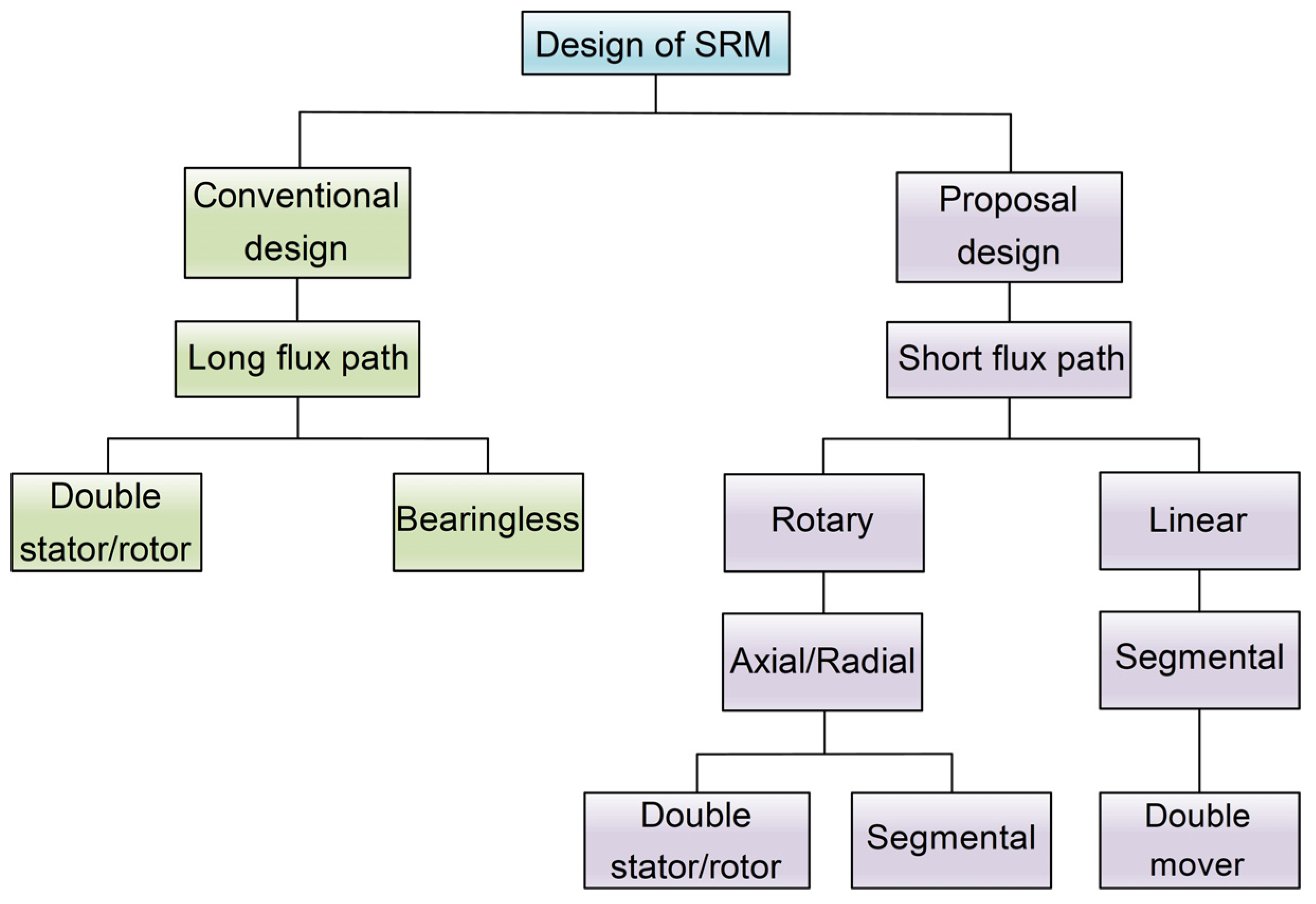
1. Introduction
2. Conventional Segmental SRM
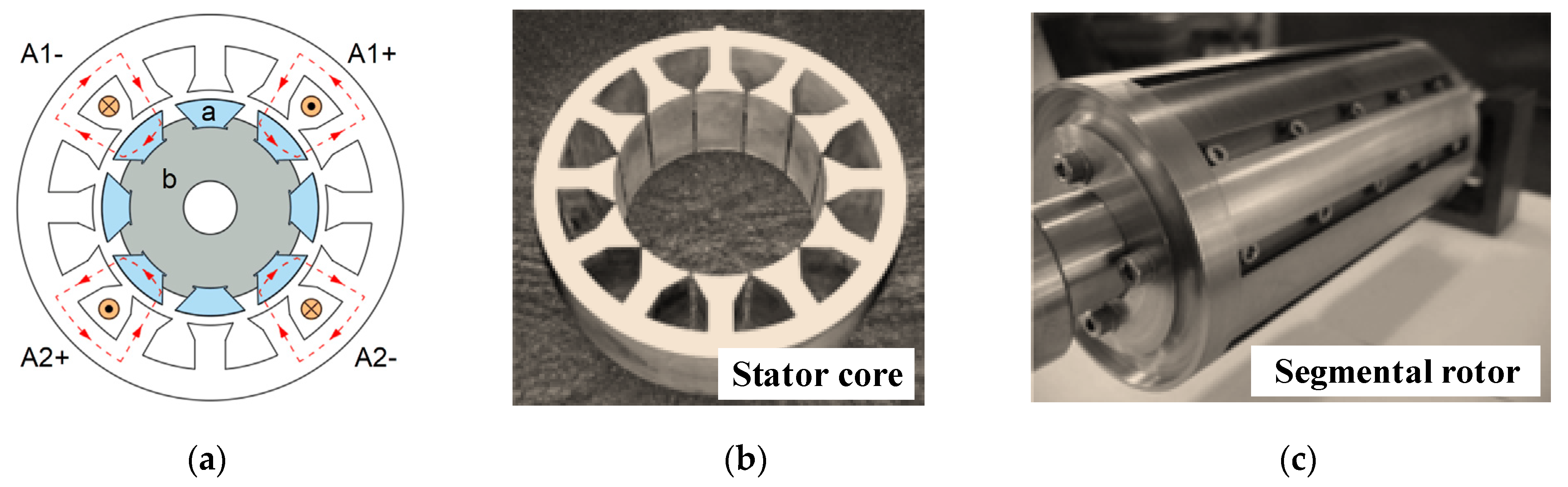
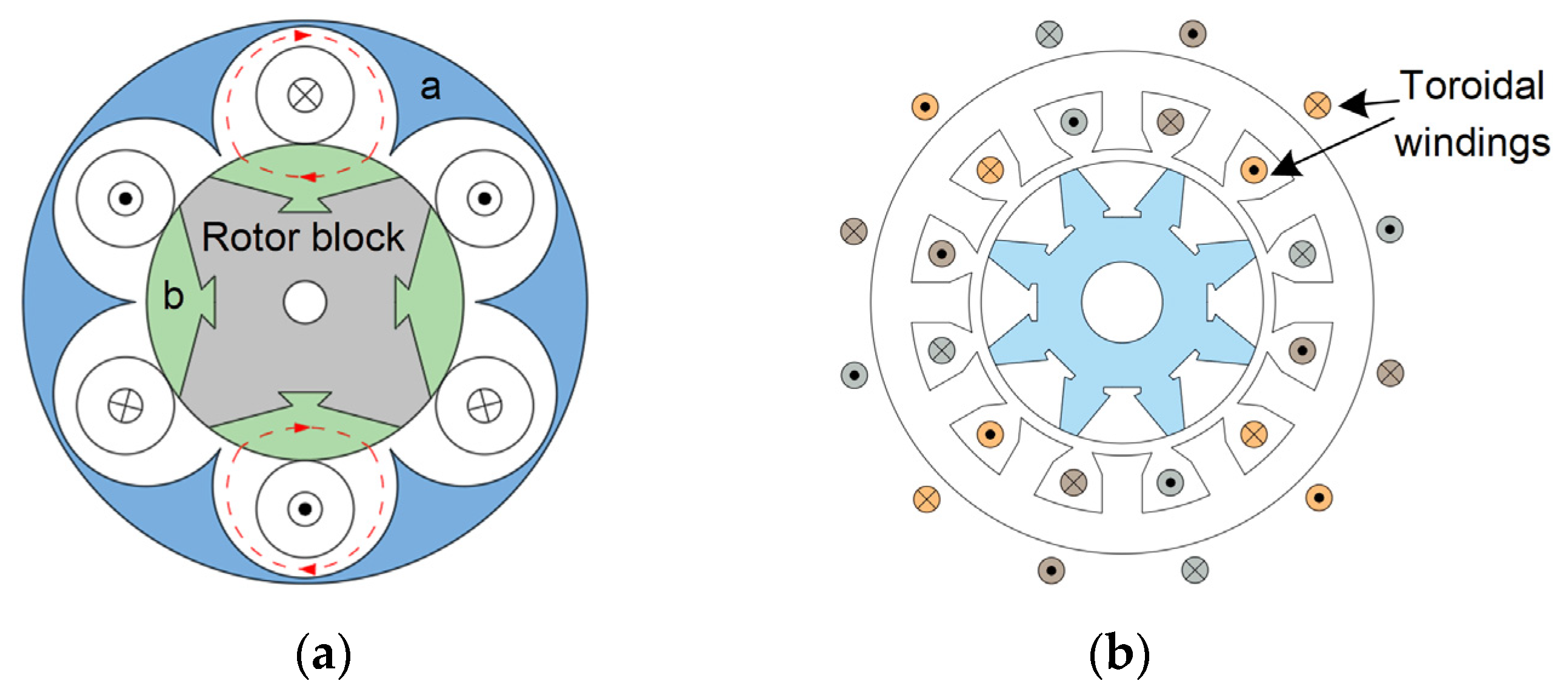
2.1. Segmental Rotor Type
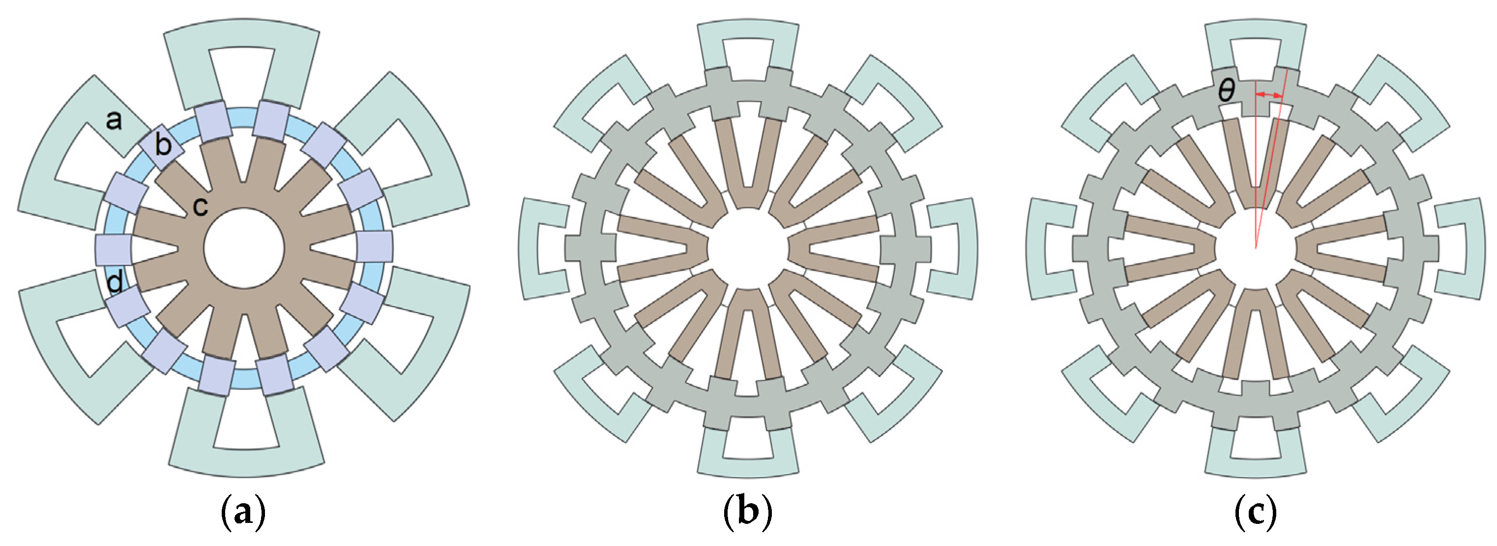
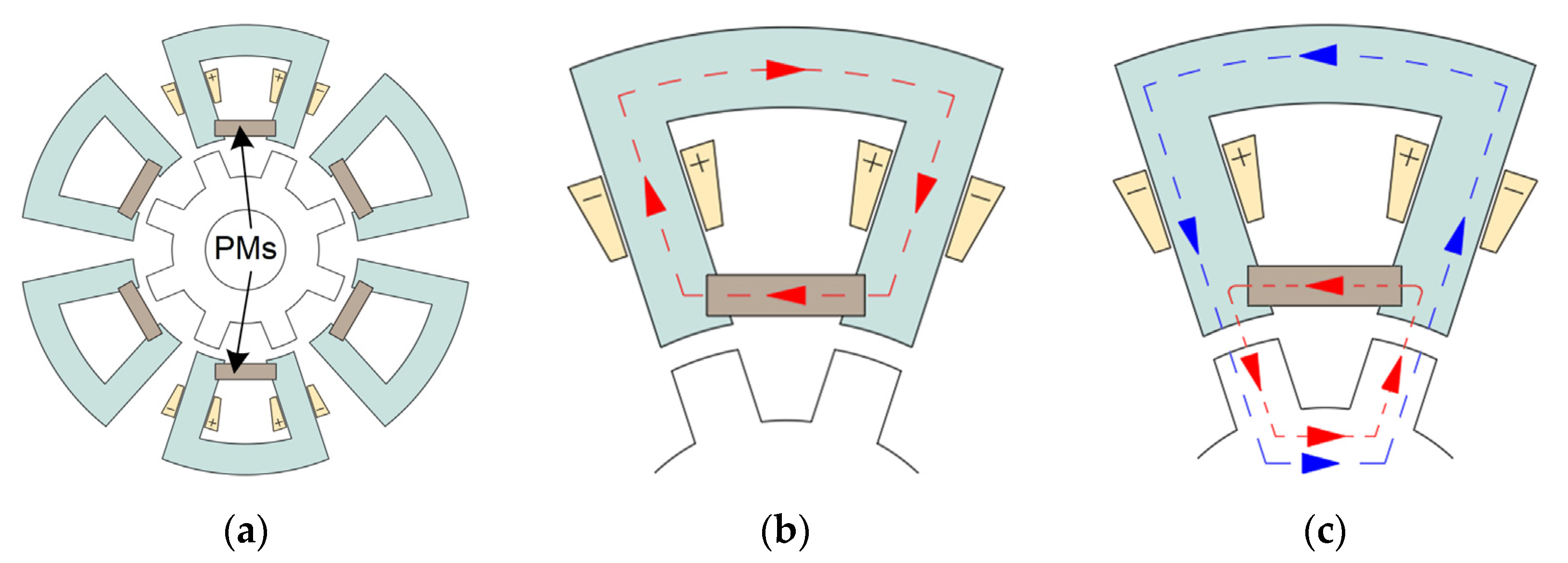
2.1.1. Structure of Segmental Rotor Type
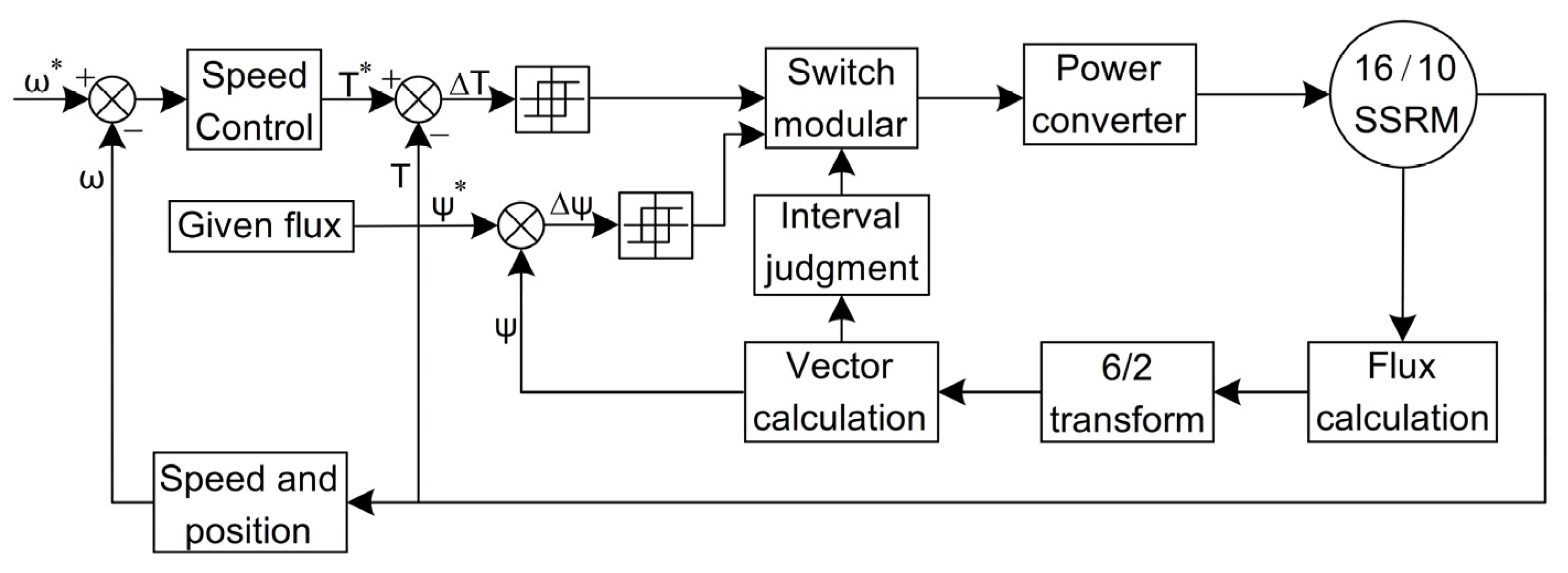
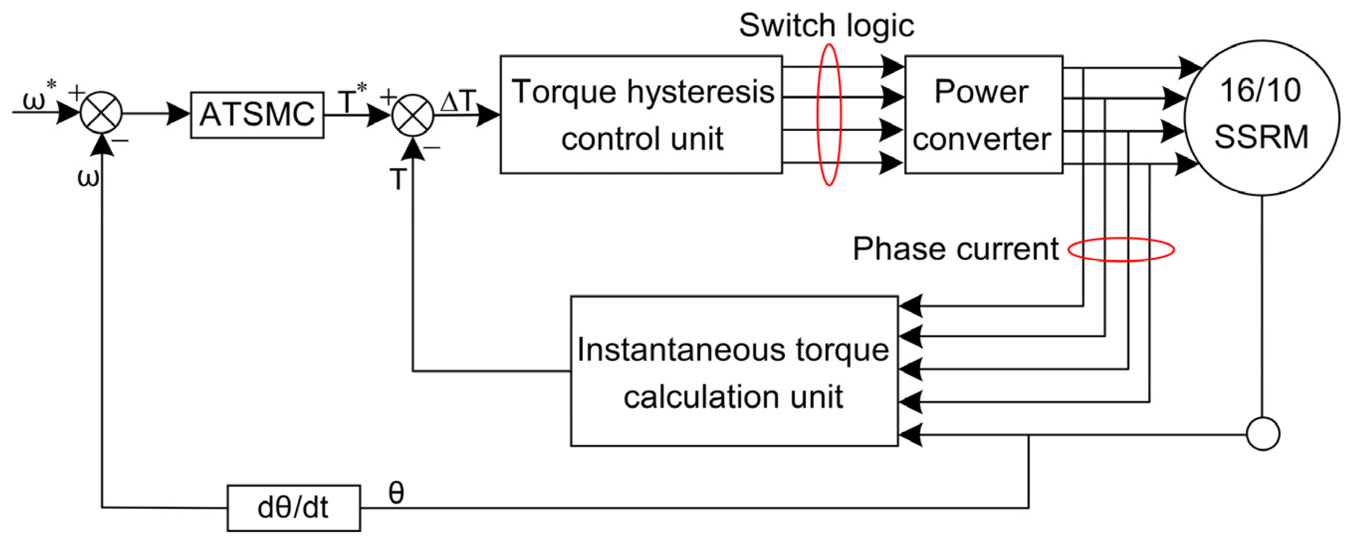
2.1.2. Control of Segmental Rotor Type
2.1.3. Electromagnetic Design of Segmental Rotor Type
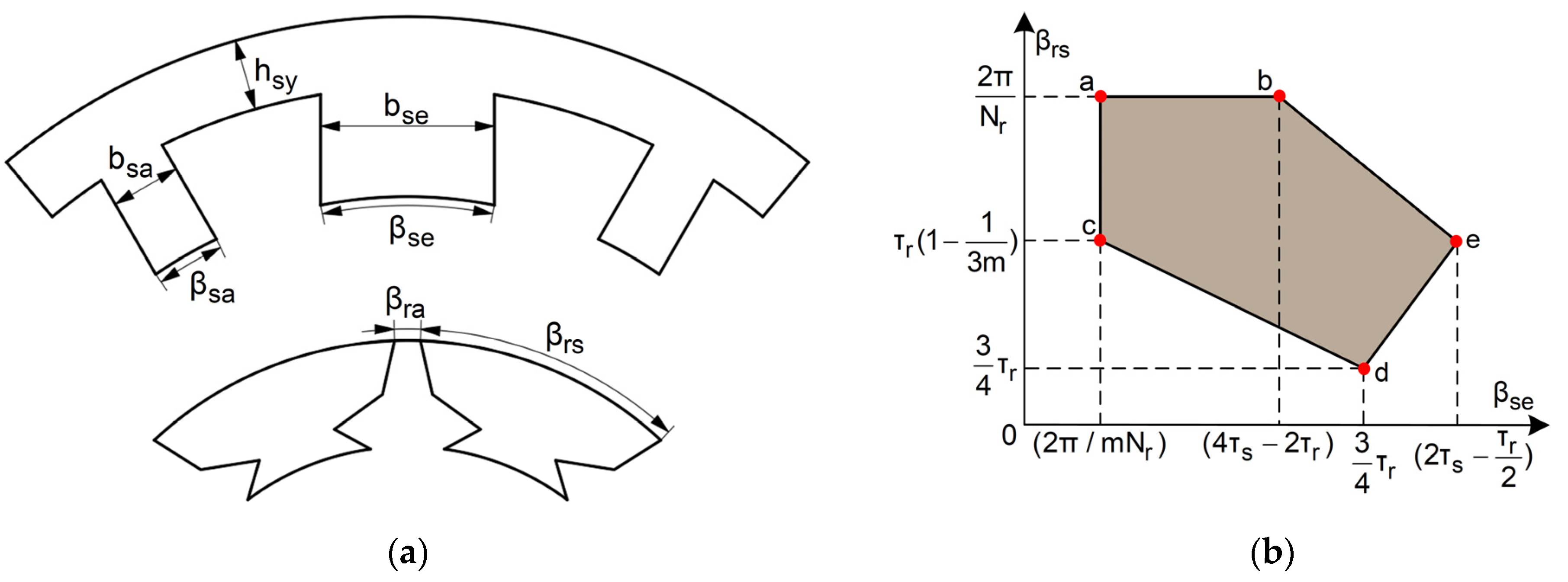
- The numbers of stator poles and rotor segments should follow (7), where LCM is the least common multiple of the number of stator poles Ns and the number of rotor poles Nr. If the number of rotor segments is too small, the leakage flux is serious, and the motor will have poor startup ability due to the large angle between the two adjacent segmented rotors. If the number of rotor segments is larger, the rotor pole is too small to meet the requirements.
- At the aligned position, the excitation pole arc βse is equal to the sum of twice the auxiliary pole arc βsa and the rotor segment inter-pole arc βra, and the rotor segment pole arc βrs is less than one rotor pole pitch, which can be expressed as (8).
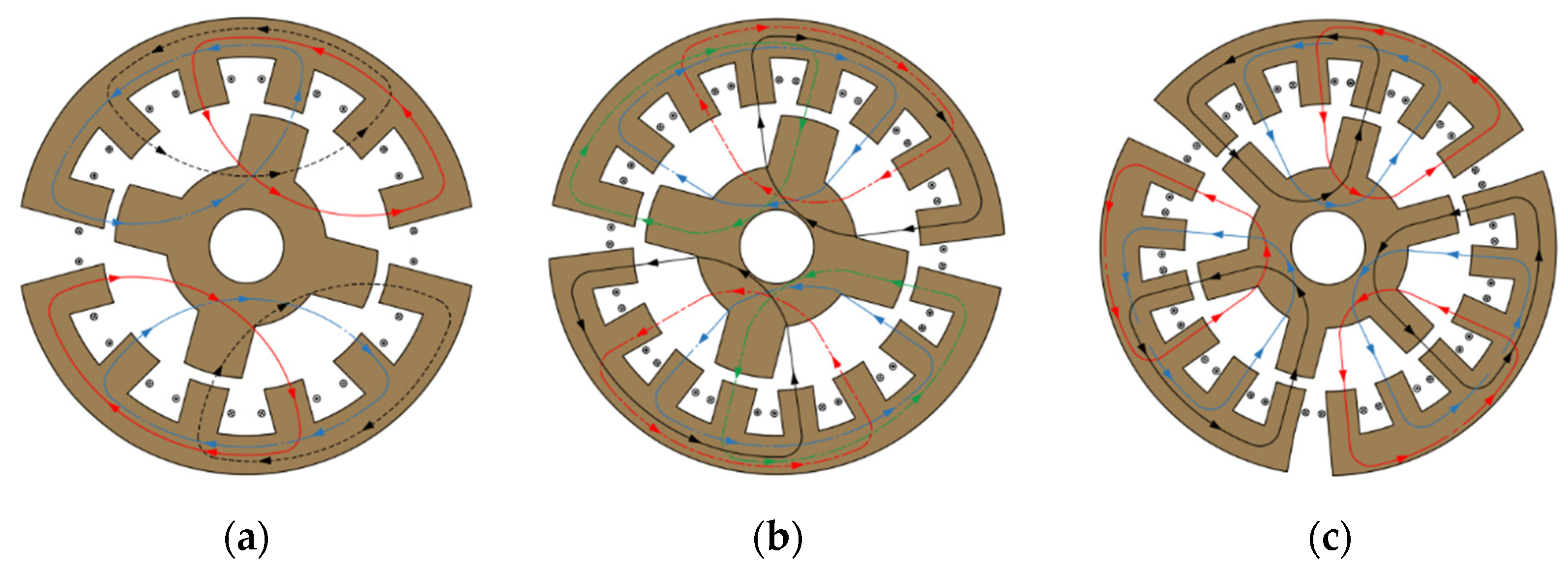
- In order to prevent mutual coupling between phases, the flux of one phase flows into the excitation pole of the adjacent phase during excitation. To maximize the flux generated by the excitation winding to the adjacent auxiliary pole, the stator and rotor pole arcs at the aligned position should satisfy (9), where τs=2π/Ns is the stator pole pitch.
- The auxiliary pole arc βsa should be larger than the arc between rotor segments arc βra to prevent the core electromagnetic utilization rate from being too low.
- Meanwhile, to ensure that the motor can be in any position with forward or reverse self-starting ability, it usually requires that the rotor segment pole arc βrs be greater than the excitation pole arc βse and not lower than the motor step angle, with the step angle expressed as 2π/(mNr).
2.2. Segmental Stator Type
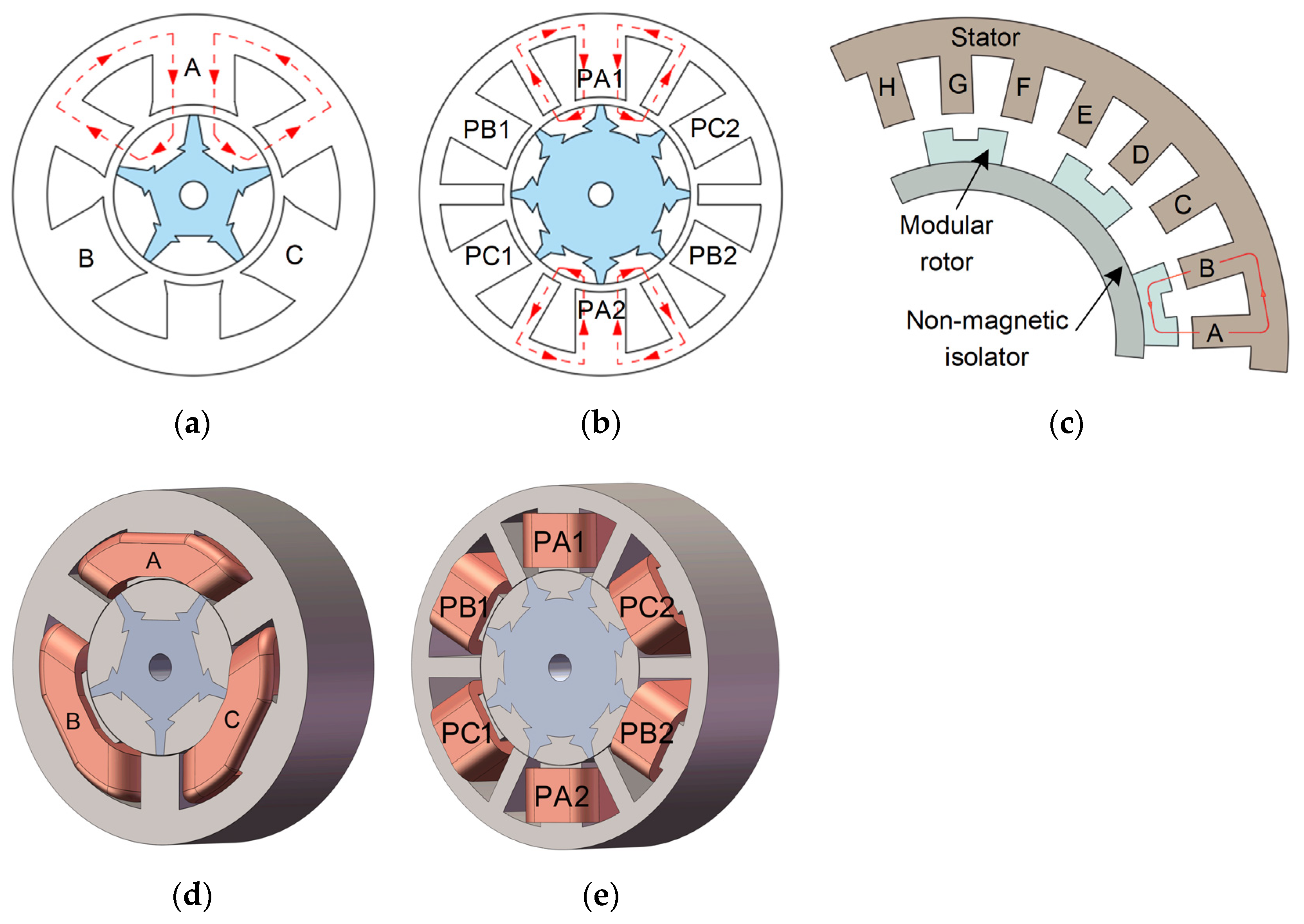
3. New Type of Segmental SRM
3.1. Double-Stator SSRM
3.2. Bearingless SSRM
3.3. Hybrid Excitation SSRM
4. Conclusions and Future Directions
- Expansion of new ontological structure: The higher degree of freedom in the design of the topology of the segmental SRM, currently aiming at permanent magnet-assisted AFSRM, segmental LSRM, and flux switching segmental SRM, combined with the segmental stator, will be an essential direction for the future development of the topological structure;
- Iron loss calculation, vibration noise, and temperature field: Recent studies on the SSRM have focused on electromagnetic properties, but little research has been done on its tower physical fields. Temperature also affects the electromagnetic performance of the motor, and vibration noise is one of the inherent disadvantages of the SSRM. Improving the research gaps of the SSRM and expanding its application area are future research priorities;
- Optimized design of structure with multiple physical fields: At present, many researchers only focus on the optimization of the electromagnetic performance of the SSRM, while in the mechanical aspects, such as vibration, noise, temperature, and other aspects, the related studies are still too few; we should have a comprehensive consideration of each optimization target, which can be combined with some advanced intelligent optimization algorithms for more comprehensive optimization. Then, the motor torque density, efficiency, vibration, noise and other performance indicators could be optimized simultaneously;
- Advanced control technology: all kinds of research are only focusing on the topology of the SSRM, while the research on its control is still very limited. Research on the motor body matching the drive topology and the control strategy are needed to further optimize the performance of the motor and broaden the application field of the SSRM, which is also an important direction for the future development.
Author Contributions
Funding
Data Availability Statement
Conflicts of Interest
Abbreviations
| SRM | switched reluctance motor |
| PMSM | permanent magnet synchronous motor |
| EVs | electric vehicles |
| SSRM | segmental switched reluctance motor |
| PMs | permanent magnets |
| IM | induction motor |
| CSRM | conventional switched reluctance motor |
| BSRM | bearingless switched reluctance motor |
| SynSRM | synchronous reluctance motor |
| FPW | full pitch winding |
| CW | concentrated winding |
| DTC | direct torque control |
| DITC | direct instantaneous torque control |
| ATSMC | adaptive terminal sliding mode control |
| AFSRM | axial field switched reluctance motors |
| MMF | magnetic motive force |
| FRFS-SRM | flux-reversal-free-stator switched reluctance motor |
| DSSRM | double-stator segmental switched reluctance motor |
| HESSRM | hybrid excitation segmented switched reluctance motor |
| LSRM | linear switched reluctance motor |
References
- Valdivia, V.; Todd, R.; Bryan, F.J.; Barrado, A.; Lázaro, A.; Forsyth, A.J. Behavioral modeling of a switched reluctance generator for aircraft power systems. IEEE Trans. Ind. Electron. 2014, 61, 2690–2699. [Google Scholar] [CrossRef]
- Yi, F.; Cai, W. Modeling, control, and seamless transition of the bidirectional battery-driven switched reluctance motor/generator drive based on integrated multiport power converter for electric vehicle applications. IEEE Trans. Power Electron. 2016, 31, 7099–7111. [Google Scholar]
- Chiba, A.; Kiyota, K.; Hoshi, N.; Takemoto, M.; Ogasawara, S. Development of a rare-earth-free SR motor with high torque density for hybrid vehicles. IEEE Trans. Energy Convers. 2015, 30, 175–182. [Google Scholar] [CrossRef]
- Gan, C.; Wu, J.; Hu, Y.; Yang, S.; Cao, W.; Guerrero, J.M. New integrated multilevel converter for switched reluctance motor drives in plug-in hybrid electric vehicles with flexible energy conversion. IEEE Trans. Power Electron. 2017, 32, 3754–3766. [Google Scholar] [CrossRef]
- Chen, H.; Gu, J. Implementation of the three-phase switched reluctance machine system for motors and generators. IEEE ASME Trans. Mechatron. 2010, 15, 421–432. [Google Scholar] [CrossRef]
- Takemoto, M.; Shimada, K.; Chiba, A. A design and characteristics of switched reluctance type bearingless motors. In Proceedings of the 4th International Symposium on Magnetic Suspension Technology, Gigu, Japan, 30 October–1 November 1997; pp. 49–63. [Google Scholar]
- Lawrenson, P.J.; Agu, L. A new unexcited synchronous machine. IEEE Proc. 1963, 110, 1275. [Google Scholar]
- Morel, L.; Fayard, H.; Vives, F.H.; Abba, G. Study of ultra high speed switched reluctance motor drive. In Proceedings of the IEEE Industry Applicatios Conference, Rome, Italy, 8–12 October 2000; pp. 87–92. [Google Scholar]
- Hamdy, R.; Fletcher, J.E.; Williams, B.W.; Finney, S.J. High-speed performance improvements of a two-phase switched reluctance machine utilizing rotor conducting screens. IEEE Trans. Energy Convers. 2002, 17, 500–506. [Google Scholar] [CrossRef]
- Mecrow, B.C.; Finch, J.W.; EI-Kharashi, E.A.; Jack, A.G. Switched reluctance motors with segmental rotors. IEE Proc. Electr. Power Appl. 2002, 149, 245–254. [Google Scholar] [CrossRef]
- Mecrow, B.C.; Finch, J.W.; EI-Kharashi, E.A.; Jack, A.G. The design of switched reluctance motors with segmental rotors. In Proceedings of the 5th International Conference on Electrical Machines (ICEM), Brugge, Belgium, 25–28 August 2002. [Google Scholar]
- Mecrow, B.C.; EI-Kharashi, E.A.; Finch, J.W.; Jack, A.G. Preliminary performance evaluation of switched reluctance motors with segmental rotors. IEEE Trans Energy Convers. 2004, 19, 679–686. [Google Scholar] [CrossRef]
- Oyama, J.; Higuchi, T.; Abe, T.; Tanaka, K. The fundamental characteristics of novel switched reluctance motor with segment core embedded in aluminum rotor block. In Proceedings of the 8th International Conference on Electrical Machines and Systems, Nanjing, China, 27–29 September 2005; pp. 515–519. [Google Scholar]
- Oyama, J.; Higuchi, T.; Abe, T.; Tanaka, K. Novel switched reluctance motor with segment core embedded in aluminum rotor block. Trans. Electr. Eng. Jpn. 2006, 126, 385–390. [Google Scholar] [CrossRef]
- Higuchi, T.; Suenaga, K.; Abe, A. Torque ripple reduction of novel segment type Switched reluctance motor by increasing phase number. In Proceedings of the International Conference on Electrical Machines and Systems, Tokyo, Japan, 15–18 November 2009; pp. 1–4. [Google Scholar]
- Higuchi, T.; Ueda, T.; Abe, T. Torque ripple reduction control of a novel segment type SRM with 2-steps slide rotor. In Proceedings of the International Power Electronics Conference, Sapporo, Japan, 21–24 June 2010; pp. 2175–2180. [Google Scholar]
- Matsuo, Y.; Higuchi, T.; Abe, T. Characteristics of a novel segment type switched reluctance motor using grain-oriented electric steel. In Proceedings of the International Conference on Electrical Machines and Systems, Beijing, China, 20–23 August 2011; pp. 1–4. [Google Scholar]
- Vattikuti, N.; Rallabandi, V.; Fernandes, B.G. A novel high torque and low weight segmented switched reluctance motor. In Proceedings of the IEEE Power Electronics Specialists Conference, Rhodes, Greece, 15–19 June 2008; pp. 1223–1228. [Google Scholar]
- Vandana, R.; Vattikuti, N.; Fernandes, B.G. A novel high power density segmented switched reluctance machine. In Proceedings of the IEEE Industry Applications Society Annual Meeting, Edmonton, AB, Canada, 5–9 October 2008; pp. 1–7. [Google Scholar]
- Chen, X.; Wu, J. Calculation of inductances with 3-D FEM for SRM with segmental rotors and fully-picthed windings. In Proceedings of the 17th International Conference on Electrical Machines and Systems, Hangzhou, China, 22–25 October 2014; pp. 1822–1824. [Google Scholar]
- Chen, X.; Deng, Z.; Wang, X.; Peng, J.; Li, X. New designs of switched reluctance motors with segmental rotors. In Proceedings of the 5th IET International Conference on Power Electronics, Machines and Drives, Brighton, UK, 19–21 April 2010; pp. 1–6. [Google Scholar]
- Mecrow, B.C.; El-Kharashi, E.A.; Finch, J.W.; Jack, A.G. Segmental rotor switched reluctance motors with single-tooth windings. IEE Proc. Electr. Power Appl. 2003, 150, 591–599. [Google Scholar] [CrossRef]
- Widmer, J.D.; Mecrow, B.C. Optimized segmental rotor switched reluctance machines with a greater number of rotor segments than stator slots. IEEE Trans. Ind. Appl. 2013, 49, 1491–1498. [Google Scholar] [CrossRef]
- Xu, Z.; Ahn, J. A novel 6/5 segmental rotor type switched reluctance motor: Concept, design and analysis. In Proceedings of the International Conference on Electrical Machines and Systems, Busan, Republic of Korea, 26–29 October 2013; pp. 582–585. [Google Scholar]
- Xu, Z.; Jeong, K.; Lee, D.; Ahn, J. Preliminary performance evaluation of a novel 12/8 segmental rotor type SRM. In Proceedings of the 19th International Conference on Electrical Machines and Systems, Chiba, Japen, 13–16 November 2016; pp. 1–5. [Google Scholar]
- Xu, Z.; Liu, J.; Kim, M.; Lee, D.; Ahn, J. Characteristics analysis and comparison of conventional and segmental rotor type 12/8 switched reluctance motors. IEEE Trans. Ind. Appl. 2019, 55, 3129–3137. [Google Scholar] [CrossRef]
- Powell, D.J.; Jewell, G.D.; Calverley, S.D.; Howe, D. Iron loss in a modular rotor switched reluctance machine for the “More-Electric” aero-engine. IEEE Trans. Magn. 2005, 41, 3934–3936. [Google Scholar] [CrossRef]
- Powell, D.J.; Jewell, G.D.; Howe, D. Rotor topologies for a switched-reluctance machine for the “more-electric” aircraft engine. IEE Proc. Electr. Power Appl. 2003, 150, 311–318. [Google Scholar] [CrossRef]
- Zhou, Z.; Sun, X.; Chen, L.; Yang, Z.; Li, K.; Zhu, J.; Guo, Y. A segmented rotor type switched reluctance machine for BSGs of hybrid electric vehicles: Concept, design and analysis. In Proceedings of the 20th International Conference on Electrical Machines and Systems, Sydeny, Australia, 11–14 August 2017; pp. 1–4. [Google Scholar]
- Sun, X.; Zhou, Z.; Chen, L.; Yang, Z.; Han, S. Performance analysis of segmented rotor switched reluctance motors with three types of winding connections for belt-driven starter generators of hybrid electric vehicles. COMPEL Int. J. Comput. Mathema. Electr. Electron. Eng. 2018, 37, 1258–1270. [Google Scholar] [CrossRef]
- Sun, X.; Zhang, X.; Han, W.; Chen, L.; Xu, X.; Yang, Z. Comparative study of fault-tolerant performance of a segmented rotor SRM and a conventional SRM. Bull. Pol. Acad. Sci. Tech. Sci. 2017, 65, 375–381. [Google Scholar] [CrossRef]
- Sun, X.; Shen, Y.; Wang, S.; Lei, G.; Yang, Z.; Han, S. Core losses analysis of a novel 16/10 segmented rotor switched reluctance BSG motor for HEVs using nonlinear lumped parameter equivalent circuit model. IEEE ASME Trans. Mecha. 2018, 23, 747–757. [Google Scholar] [CrossRef]
- Sun, X.; Diao, K.; Lei, G.; Guo, Y.; Zhu, J. Study on segmented-rotor switched reluctance motors with different rotor pole numbers for BSG system of hybrid electric vehicles. IEEE Trans. Veh. Technol. 2019, 68, 5537–5547. [Google Scholar] [CrossRef]
- Lawrenson, P.J.; Stephenson, J.M.; Blenkinsop, P.T.; Corda, J.; Fulton, N.N. Variable-speed switched reluctance motors. IEE Proc. Electr. Power Appl. 1980, 127, 253–265. [Google Scholar] [CrossRef]
- Vandana, R.; Fernandes, B.G. Design methodology for high-performance segmented rotor switched reluctance motors. IEEE Trans. Energy Convers. 2015, 30, 11–21. [Google Scholar]
- Sun, X.; Diao, K.; Lei, G.; Guo, Y.; Zhu, J. Real-time HIL emulation for a segmented-rotor switched reluctance motor using a new magnetic equivalent circuit. IEEE Trans. Power Electron. 2020, 35, 3841–3849. [Google Scholar] [CrossRef]
- Wang, B.; Lee, D.; Ahn, J. A novel axial field SRM with segmental rotor: Concept, design and analysis. In Proceedings of the 2013 Workshop on Power Electronics and Power Quality Applications, Bogota, Colombia, 6–7 July 2013; pp. 1–6. [Google Scholar]
- Wang, B.; Lee, D.; Ahn, J. Segmental rotor axial field switched reluctance motor with single teeth winding. In Proceedings of the IEEE 23rd International Symposium on Industrial Electronics, Istanbul, Turkey, 1–4 June 2014; pp. 890–895. [Google Scholar]
- Sun, W.; Li, Q.; Sun, L.; Zhu, L.; Li, L. Electromagnetic analysis on novel rotor-segmented axial-field SRM based on dynamic magnetic equivalent circuit. IEEE Trans. Magn. 2019, 55, 1–5. [Google Scholar] [CrossRef]
- Hall, R.; Jack, A.G.; Mecrow, B.C.; Mitcham, A.J. Design and initial testing of an outer rotating segmented rotor switched reluctance machine for an aero-engine shaft-line-embedded starter/generator. In Proceedings of the IEEE International Conference on Electric Machines and Drives, San Antonio, TX, USA, 15 May 2005; pp. 1870–1877. [Google Scholar]
- Vandana, R.; Fernandes, B.G. Segmented switched reluctance motor with novel winding and excitation strategy. In Proceedings of the International Conference on Electrical Machines, Rome, Italy, 6–8 September 2010; pp. 1–4. [Google Scholar]
- Nikam, S.P.; Rallabandi, V.; Fernandes, B.G. A high-torque-density permanent-magnet free motor for in-wheel electric vehicle application. IEEE Trans. Ind. Appl. 2012, 48, 2287–2295. [Google Scholar] [CrossRef]
- Vandana, R.; Nikam, S.; Fernandes, B.G. High torque polyphase segmented switched reluctance motor with novel excitation strategy. IET Electr. Power Appl. 2012, 6, 375. [Google Scholar] [CrossRef]
- Zhang, H. Design and Control of a Novel 12/8 Segmented Rotor Type SRM. Ph.D. Thesis, Shengyang University of Technology, Shenyang, China, 2015. [Google Scholar]
- Chen, L.; Wang, H.; Sun, X.; Cai, Y.; Li, K.; Diao, K.; Wu, J. Development of a digital control system for a belt-driven starter generator segmented switched reluctance motor for hybrid electric vehicles. Proc. Inst. Mech. Eng. Part I J. Syst. Control Eng. 2020, 234, 975–984. [Google Scholar] [CrossRef]
- Zhou, Z. A Segmented-Rotor Switched Reluctance Motor and Its Direct Torque Control for the BSG Used in Mild Hybrid Electric Vehicles. Ph.D. Thesis, Jiangsu University, Zhenjiang, China, 2019. [Google Scholar]
- Sun, X.; Feng, L.; Diao, K.; Yang, Z. An improved direct instantaneous torque control based on adaptive terminal sliding mode for a segmented-rotor SRM. IEEE Trans Ind. Electron. 2021, 68, 10569–10579. [Google Scholar] [CrossRef]
- Lee, C.; Krishnan, R.; Lobo, N.S. Novel two-phase switched reluctance machine using common-pole E-core structure: Concept, analysis, and experimental verification. IEEE Trans. Ind. Appl. 2009, 45, 703–711. [Google Scholar] [CrossRef]
- Tanujaya, M.; Lee, D.; Ahn, J. Characteristic analysis of a novel 6/5 c-core type three-phase switched reluctance motor. In Proceedings of the International Conference on Electrical Machines and Systems, Beijing, China, 20–23 August 2011; pp. 1–6. [Google Scholar]
- Trung Hieu, P.; Lee, D.; Ahn, J. Design and control of a high speed segmental stator 4/3 switched reluctane motor. In Proceedings of the IEEE Transportation Electrification Conference and Expo, Asia-Pacific, Busan, Korea, 1–4 June 2016; pp. 767–772. [Google Scholar]
- Lee, D.; Trung Hieu, P.; Ann, J. Design and operation characteristics of four-two pole high-speed SRM for torque ripple reduction. IEEE Trans. Ind. Electron. 2013, 60, 3637–3643. [Google Scholar] [CrossRef]
- Lobo, N.S.; Swint, E.; Krishnan, R. M-phase N-segment flux-reversal-free stator switched reluctance machines. In Proceedings of the IEEE Industry Applications Society Annual Meeting, Edmonton, Canada, 5–9 October 2008; pp. 1–8. [Google Scholar]
- Shang-Hsun, M.; Mi-Ching, T. A novel switched reluctance motor with C-core stators. IEEE Trans. Magn. 2005, 41, 4413–4420. [Google Scholar] [CrossRef]
- Ding, W.; Hu, Y.; Wu, L. Characteristics comparison of conventional and modular E-core stator with segmental rotor switched reluctance motors. In Proceedings of the 17th International Conference on Electrical Machines and Systems, Hangzhou, China, 22–25 October 2014; pp. 1797–1801. [Google Scholar]
- Ding, W.; Hu, Y.; Wu, L.; Yang, S. Comprehensive research of modular E-core stator hybrid-flux switched reluctance motors with segmented and non-segmented rotors. IEEE Trans. Energy Convers. 2017, 32, 382–393. [Google Scholar] [CrossRef]
- Ding, W.; Ying, G.; Liu, L.; Lou, J. Magnetic circuit model and finite-element analysis of a modular switched reluctance machine with E-core stators and multi-layer common rotors. IET Electr. Power Appl. 2014, 8, 296–309. [Google Scholar] [CrossRef]
- Ding, W.; Hu, Y.; Fu, H.; Chen, Q. Analysis of novel segmented E-shaped stator switched reluctance machines with segmental and conventional rotor topologies. In Proceedings of the 11th International Conference on Ecological Vehicles and Renewable Energies, Monte Carlo, Monaco, 6–8 April 2016; pp. 1–8. [Google Scholar]
- Ding, W.; Hu, Y.; Wu, L. Analysis and development of novel three-phase hybrid magnetic paths switched reluctance motors using modular and segmental structures for EV applications. IEEE/ASME Trans. Mechatronics. 2015, 20, 2437–2451. [Google Scholar] [CrossRef]
- Szabo, L.; Ruba, M. Segmental stator switched reluctance machine for safety-critical applications. IEEE Trans. Ind. Appl. 2012, 48, 2223–2229. [Google Scholar] [CrossRef]
- Ruba, M.; Viorel, I.A.; Szabo, L. Modular stator switched reluctance motor for fault tolerant drive systems. IET Electr. Power Appl. 2013, 7, 159–169. [Google Scholar] [CrossRef]
- Asgar, M.; Afjei, E.; Torkaman, H. A new strategy for design and analysis of a double-stator switched reluctance motor: Electromagnetics, FEM, and experiment. IEEE Trans. Magn. 2015, 51, 1–8. [Google Scholar] [CrossRef]
- Bostanci, E.; Gu, L.; Cosoroaba, E.; Moallem, M.; Fahimi, B. Performance improvement and comparison of concentrated winding segmental rotor and double stator switched reluctance machines. In Proceedings of the IEEE Conference on Electromagnetic Field Computation, Miami, FL, USA, 13–16 November 2016; p. 1. [Google Scholar]
- Abbasian, M.; Moallem, M.; Fahimi, B. Double-stator switched reluctance machines (DSSRM): Fundamentals and magnetic force analysis. IEEE Transa. Energy Convers. 2010, 25, 589–597. [Google Scholar] [CrossRef]
- Isfahani, A.H.; Fahimi, B. Comparison of mechanical vibration between a double-stator switched reluctance machine and a conventional switched reluctance machine. IEEE Trans. Magn. 2014, 50, 293–296. [Google Scholar] [CrossRef]
- Cosoroaba, E.; Wang, W.; Fahimi, B. Comparative study of two winding configurations for a double stator switched reluctance machine. In Proceedings of the 2014 International Conference on Electrical Machines, Berlin, Germany, 2–5 September 2014; pp. 1013–1017. [Google Scholar]
- Kondelaji, M.A.J.; Mirsalim, M. Segmented-rotor modular switched reluctance motor with high torque and low torque ripple. IEEE Trans. Transp. Electrif. 2020, 6, 62–72. [Google Scholar] [CrossRef]
- Cheng, H.; Liao, S.; Yan, W. Development and Performance Analysis of Segmented-Double-Stator Switched Reluctance Machine. IEEE Trans. Ind. Electron. 2022, 69, 1298–1309. [Google Scholar] [CrossRef]
- Yan, W.; Cheng, H.; Liao, S.; Liu, Y. Design of a low-ripple double-modular-stator switched reluctance machine for electric vehicle applications. IEEE Trans. Transp. Electrif. 2021, 7, 1349–1358. [Google Scholar] [CrossRef]
- Yan, W.; Chen, H.; Ma, X.; Orabi, M.; Lv, Z. A low ripple double modular-stator switched reluctance machine for electric vehicles applications. In Proceedings of the IEEE International Conference on Applied Superconductivity and Electromagnetic Devices, Tianjin, China, 16–18 October 2020; pp. 1–2. [Google Scholar]
- Sun, Q.; Wu, J.; Gan, C.; Shi, C.; Guo, J. DSSRM design with multiple pole arcs optimization for high torque and low torque ripple applications. IEEE Access 2018, 6, 27166–27175. [Google Scholar] [CrossRef]
- Lin, C.; Wang, W.; Fahimi, B. Optimal design of double stator switched reluctance machine (DSSRM). In Proceedings of the IEEE International Symposium on Industrial Electronics, Hangzhou, China, 28–31 May 2012; pp. 719–724. [Google Scholar]
- Wang, W.; Luo, M.; Cosoroaba, E.; Fahimi, B.; Kiani, M. Rotor shape investigation and optimization of double stator switched reluctance machine. IEEE Trans. Magn. 2015, 51, 1–4. [Google Scholar] [CrossRef]
- Tavakkoli, M.A.; Moallem, M. Torque ripple mitigation of double stator switched reluctance motor (DSSRM) using a novel rotor shape optimization. In Proceedings of the IEEE Energy Conversion Congress and Exposition, Raleigh, NC, USA, 15–20 September 2012; pp. 848–852. [Google Scholar]
- Peng, W.; Xu, Z.; Lee, D.; Ann, J. Control of radial force in double stator type bearingless switched reluctance motor. J. Electr. Eng. Technol. 2013, 8, 766–772. [Google Scholar] [CrossRef][Green Version]
- Huang, Y.; Huang, F.; Yuan, Y.; Yang, F.; Xie, K. Design and analysis of a novel bearingless segmented switched reluctance motor. IEEE Access 2019, 7, 94342–94349. [Google Scholar] [CrossRef]
- Fan, Z.; Xu, Z.; Wang, H.; Zhang, F. Characteristics analysis of a novel 12/8 double stator bearingless switched reluctance motor. In Proceedings of the 24th International Conference on Electrical Machines and Systems, Gyeongju, Republic of Korea, 31 October–3 November 2021; pp. 333–338. [Google Scholar]
- Xu, Z.; Zhou, Z.; Fan, Z.; Qi, Y.; Zhang, F. Characteristics analysis and comparison of conventional and segmental rotor type 12/8 double stator bearingless switched reluctance motors. In Proceedings of the Joint MMM-Intermag Conference, New Orleans, LA, USA, 10–14 January 2022; pp. 1–5. [Google Scholar]
- Hasegawa, Y.; Nakamura, K.; Ichinokura, O. Basic consideration of switched reluctance motor with auxiliary windings and permanent magnets. In Proceedings of the IEEE International Conference on Electrical Machines, Marseille, France, 2–5 September 2012; pp. 92–97. [Google Scholar]
- Kenji, N.; Kohei, M.; Osam, I. Characteristics of a novel switched reluctance motor having permanent magnets between the stator pole-tips. In Proceedings of the European Conference on Power Electronics and Applications, Aalborg, Denmark, 2–5 September 2007; pp. 1–5. [Google Scholar]
- Hwang, H.; Bae, S.; Lee, C. Analysis and design of a hybrid rare-earth-free permanent magnet reluctance machine by frozen permeability method. IEEE Trans. Magn. 2016, 52, 8106304. [Google Scholar] [CrossRef]
- Ullah, S.; McDonald, S.P.; Martin, R.; Atkinson, G.J. A permanent magnet assisted switched reluctance machine for more electric aircraft. In Proceedings of the International Conference on Electrical Machines, Lausanne, Switzerland, 4–7 September 2016; pp. 79–85. [Google Scholar]
- Pang, M.; Wang, H.; Zhou, G.; Li, F.; Wei, X.; Zhang, M. Design and analysis of a two-phase permanent-magnet-assisted switched reluctance motor. In Proceedings of the 21st International Conference on Electrical Machines and Systems, Jeju, Republic of Korea, 7–10 October 2018; pp. 1956–1961. [Google Scholar]
- Zhu, J.; Cheng, K.W.E.; Xue, X. Design and analysis of a new enhanced torque hybrid switched reluctance motor. IEEE Trans. Energy Convers. 2018, 33, 1965–1977. [Google Scholar] [CrossRef]
- Ding, W.; Yang, S.; Hu, Y.; Li, S.; Wang, T.; Yin, Z. Design Consideration and Evaluation of a 12/8 High-Torque Modular-Stator Hybrid Excitation Switched Reluctance Machine for EV Applications. IEEE Trans. Ind. Electron. 2017, 64, 9221–9232. [Google Scholar] [CrossRef]
- Andrada, P.; Blanqué, B.; Martínez, E.; Torrent, M. A novel type of hybrid reluctance motor drive. IEEE Trans. Ind. Electron. 2014, 8, 4337–4345. [Google Scholar] [CrossRef]
- Ding, W.; Fu, H.; Hu, Y. Characteristics assessment and comparative study of a segmented-stator permanent-magnet hybrid-excitation SRM drive with high-torque capability. IEEE Trans. Power Electron. 2018, 33, 482–500. [Google Scholar] [CrossRef]
- Tai, W.; Tsai, M.; Gaing, Z.; Huang, P.; Hsu, Y. Novel stator design of double salient permanent magnet motor. IEEE Trans. Magn. 2014, 50, 1–4. [Google Scholar] [CrossRef]
- Kondelaji, M.A.J.; Mirsalim, M. Double-stator PM-assisted modular variable reluctance motor for EV applications. In Proceedings of the 9th Annual Power Electronics, Drives Systems and Technologies Conference, Tehran, Iran, 13–15 February 2018; pp. 236–240. [Google Scholar]
- Ganji, B.; Askari, M.H. Different topologies for linear switched reluctance motor with segmental translator. In Proceedings of the 24th Iranian Conference on Electrical Engineering, Shiraz, Iran, 10–12 May 2016; pp. 874–878. [Google Scholar]
- Yi, X.; Zhu, C.; Huang, C.; Wang, D.; Wang, X. Design Optimization of Linear Switched Reluctance Motor with Segmental Mover. In Proceedings of the 13th International Symposium on Linear Drives for Industry Applications, Wuhan, China, 1–3 July 2021; pp. 1–6. [Google Scholar]
- Wang, D.; Du, X.; Zhang, D.; Wang, X. Design, optimization, and prototyping of segmental-type linear switched-reluctance motor with a toroidally wound mover for vertical propulsion application. IEEE Trans. Ind. Electron. 2018, 65, 1865–1874. [Google Scholar] [CrossRef]


| SSRM Topologies | Winding Topologies | Advantages | Disadvantages | Applications |
|---|---|---|---|---|
| (Radial field) segmental rotor type | FPW [10,13,18] |
|
|
|
| CW [22,24,26,33,35,44] |
|
|
| |
| Axial field segmental rotor type | CW [37,38] |
|
|
|
| Segmental stator type | CW [48,49,50,53] |
|
|
|
| Double-stator type | FPW [67,68] |
|
|
|
| Bearingless type | CW [76,77] |
|
|
|
| Hybrid excitation type | FPW [84,88] |
|
|
|
Publisher’s Note: MDPI stays neutral with regard to jurisdictional claims in published maps and institutional affiliations. |
© 2022 by the authors. Licensee MDPI, Basel, Switzerland. This article is an open access article distributed under the terms and conditions of the Creative Commons Attribution (CC BY) license (https://creativecommons.org/licenses/by/4.0/).
Share and Cite
Xu, Z.; Li, T.; Zhang, F.; Zhang, Y.; Lee, D.-H.; Ahn, J.-W. A Review on Segmented Switched Reluctance Motors. Energies 2022, 15, 9212. https://doi.org/10.3390/en15239212
Xu Z, Li T, Zhang F, Zhang Y, Lee D-H, Ahn J-W. A Review on Segmented Switched Reluctance Motors. Energies. 2022; 15(23):9212. https://doi.org/10.3390/en15239212
Chicago/Turabian StyleXu, Zhenyao, Tao Li, Fengge Zhang, Yue Zhang, Dong-Hee Lee, and Jin-Woo Ahn. 2022. "A Review on Segmented Switched Reluctance Motors" Energies 15, no. 23: 9212. https://doi.org/10.3390/en15239212
APA StyleXu, Z., Li, T., Zhang, F., Zhang, Y., Lee, D.-H., & Ahn, J.-W. (2022). A Review on Segmented Switched Reluctance Motors. Energies, 15(23), 9212. https://doi.org/10.3390/en15239212